Embed Size (px)
Citation preview

THE Mobile Broadband Standard
© 3GPP 2011 3GPP Workshop, Bangalore, 30 May 2011
LTE Radio Physical Layer
Sadayuki Abeta
NTT DOCOMO

THE Mobile Broadband Standard
© 3GPP 2011 3GPP Workshop, Bangalore, 30 May 2011
Contents
IntroductionDownlink Aspects for LTE Release 8
Uplink Aspects for LTE Release 8
Enhancements for LTE-Advanced (Release 10 and beyond)
2

THE Mobile Broadband Standard
© 3GPP 2011 3GPP Workshop, Bangalore, 30 May 2011
Physical Layer Specifications
TS 36.201 E-UTRA Physical layer: General description .
TS 36.211 E-UTRA Physical channels and modulation .
TS 36.212 E-UTRA Multiplexing and channel coding .
TS 36.213 E-UTRA Physical layer procedures .
TS 36.214 E-UTRA Physical layer - Measurements
The latest version of the specifications can be downloaded from: • http://www.3gpp.org/ftp/Specs/
3

THE Mobile Broadband Standard
© 3GPP 2011 3GPP Workshop, Bangalore, 30 May 2011
LTE Release 8 Major Parameters
Access Scheme DL OFDMA
UL SC-FDMA
Bandwidth 1.4, 3, 5, 10, 15, 20 MHz
Minimum TTI 1 ms
Sub-carrier spacing 15 kHz
Cyclic prefix length Short 4.7 ms
Long 16.7 ms
Modulation QPSK, 16QAM, 64QAM
Spatial multiplexing Single layer for UL per UEUp to 4 layers for DL per UEMU-MIMO supported for UL and DL
4

THE Mobile Broadband Standard
© 3GPP 2011 3GPP Workshop, Bangalore, 30 May 2011
Transmission Resource structure
Basic unit of resource is the Physical Resource Block (PRB)
12 sub-carriers x 0.5 ms
Allocated in pairs (in time domain)
1 sub-carrier x 1 symbol = 1 resource element (RE)
Spatial domain measured in “layers”
One downlink slot, Tslot
subca
rrie
rsN
BW
DL
subca
rrie
rsN
BW
DL
NB
WD
L
Resource element
OFDM symbolsDLsymbN OFDM symbolsDLsymbN
On
e re
sourc
e b
lock
, N
BW
subcar
riers
RB
On
e re
sourc
e b
lock
, N
BW
subcar
riers
RB
5

THE Mobile Broadband Standard
© 3GPP 2011 3GPP Workshop, Bangalore, 30 May 2011
One radio interface for FDD and TDD
Supports both FDD and TDD
• FDD
• TDD
#0 #1 #2 #3 #19#18
One radio frame, Tf = 307200Ts = 10 ms
One slot, Tslot = 15360Ts = 0.5 ms
One subframe
One slot,
Tslot=15360Ts
GP UpPTSDwPTS
One radio frame, Tf = 307200Ts = 10 ms
One half-frame, 153600Ts = 5 ms
30720Ts
One subframe,
30720Ts
GP UpPTSDwPTS
Subframe #2 Subframe #3 Subframe #4Subframe #0 Subframe #5 Subframe #7 Subframe #8 Subframe #9
6

THE Mobile Broadband Standard
© 3GPP 2011 3GPP Workshop, Bangalore, 30 May 2011
Contents
Introduction
Downlink Aspects for LTE Release 8Uplink Aspects for LTE Release 8
Enhancements for LTE-Advanced (Release 10 and beyond)
7

THE Mobile Broadband Standard
© 3GPP 2011 3GPP Workshop, Bangalore, 30 May 2011
Cell acquisition signalling
Synchronisation signals (SS) in subframes 0 and 5 of each 10 ms radio frame• Used in initial cell search• Common scheme irrespective to bandwidth simplify the procedure
Physical broadcast channel (PBCH) in subframe 0 of each radio frame• Carries the Master Information Block (MIB)
• Includes indication of system bandwidth• Robust design for cell-wide coverage:
• Low rate, QPSK, robust channel coding (1/3-rate tail-biting convolutionalcode with repetition), 40 ms TTI
• CRC indicates number of transmit antennas (SS and PBCH are transparent to number of antenna)
40ms TTI of BCH
one 10 ms radio frame
6 R
Bs
1 coded MIB
8

THE Mobile Broadband Standard
© 3GPP 2011 3GPP Workshop, Bangalore, 30 May 2011
Reference Signals (RS)
In Rel-8, cell-specific RS are provided for 1, 2 or 4 antenna ports• Pattern designed for effective channel estimation
• Sparse diamond pattern supports frequency-selective channels and high-mobility with low overhead
• Up to 6 cell-specific frequency shifts are configurable
• Power-boosting can be applied on the REs used for RS
• QPSK sequence with low PAPR
R 3
R 3
R 3
R 3 R
0
R 0
R 0
R 0
R 0
R 0
R 0
R 0
R 1
R 1
R 1
R 1
R 1
R 1
R 1
R 1
R 2
R 2
R 2
R 2
Antenna port 0 Antenna port 2 Antenna port 1 Antenna port 3
time
frequency
9

THE Mobile Broadband Standard
© 3GPP 2011 3GPP Workshop, Bangalore, 30 May 2011
UE-specific Reference Signals
In Rel-8:• UE-specific (precoded) RS may be provided in
data transmissions to specific UEs
In Rel-9:• UE-specific RS extended to dual-layer transmission
• CDM between RS of the two layers
0l
even-numbered slots odd-numbered slots
Antenna port 5
5R
5R
5R
5R
5R
5R
5R
5R
5R
5R
5R
5R
0l 6l6l
7R7R7R7R
7R7R7R7R
7R7R7R7R
8R 8R8R 8R
8R 8R8R 8R
8R 8R8R 8R
10

THE Mobile Broadband Standard
© 3GPP 2011 3GPP Workshop, Bangalore, 30 May 2011
Downlink Channel Structure
Subframe
Downlink control channel region
PDSCH PDSCH PDSCH
Frequency
TimeCFI=1CFI=3
CFI=2
Flexible control design to avoid unnecessary overhead• Control region is first 1-3 OFDM symbols in each subframe (2-4 in
narrow bandwidths)• Control region size (CFI: control channel format indicator) is
dynamically variableData transmission on Physical Downlink Shared Channel (PDSCH)
11

THE Mobile Broadband Standard
© 3GPP 2011 3GPP Workshop, Bangalore, 30 May 2011
Downlink control signaling
Physical Control Format Indicator Channel (PCFICH) indicates the control region size (CFI)
• Located in first OFDM symbol of each subframe
• PCFICH is designed to be robust
– 16 QPSK symbols transmitted with full frequency diversity
Physical Downlink Control Channel (PDCCH) carries Downlink Control Information (DCI) messages:
• downlink resource assignments
• uplink resource grants
• uplink power control commands
Physical Hybrid ARQ Indicator Channel (PHICH) carries ACK/NACK for UL data transmissions
12

THE Mobile Broadband Standard
© 3GPP 2011 3GPP Workshop, Bangalore, 30 May 2011
Downlink data transmission
PDSCH carries user data, broadcast system information, paging messages
Transmission resources are assigned dynamically by PDCCH
• Localised (suitable for frequency domain scheduling) or
• distributed (suitable for maximising frequency diversity)
One subframe = 1 ms
Data for UE2:
Data for UE3:
12 subcarriers
Data for UE1:
(localised)
(distributed)
13

THE Mobile Broadband Standard
© 3GPP 2011 3GPP Workshop, Bangalore, 30 May 2011
PDSCH transmission modes
In Rel-9, each UE is configured in one of 8 “transmission modes” for PDSCH reception:• Mode 1: Single antenna port, port 0
• Mode 2: Transmit diversity
• Mode 3: Open-loop spatial multiplexing
• Mode 4: Closed-loop spatial multiplexing
• Mode 5: MU-MIMO
• Mode 6: Closed-loop spatial multiplexing, single layer
• Mode 7: Single antenna port, UE-specific RS (port 5)
• Mode 8 (new in Rel-9): Single or dual-layer transmission with UE-specific RS (ports 7 and/or 8)
(in each case, transmit diversity is also available as a fallback)
14

THE Mobile Broadband Standard
© 3GPP 2011 3GPP Workshop, Bangalore, 30 May 2011
Contents
Introduction
Downlink Aspects for LTE Release 8
Uplink Aspects for LTE Release 8Enhancements for LTE-Advanced (Release 10 and beyond)
15

THE Mobile Broadband Standard
© 3GPP 2011 3GPP Workshop, Bangalore, 30 May 2011
Uplink multiple access: SC-FDMA
Same parameterisation as downlink
DFT precoding to ensure low PAPR / cubic metric
Cyclic prefix facilitates frequency-domain equalisation at eNodeB
16

THE Mobile Broadband Standard
© 3GPP 2011 3GPP Workshop, Bangalore, 30 May 2011
UL transmission resource allocation
Same structure of PRBs in frequency domain as downlink
Contiguous PRB allocation to keep single carrier property
Possibility to configure frequency hopping to increase frequency diversity
Number of allocated PRBs for a given user in a given subframe is in multiples of 2, 3 and 5 for low-complexity DFT implementation
One subframe = 1 ms
12 sub-carriers
17

THE Mobile Broadband Standard
© 3GPP 2011 3GPP Workshop, Bangalore, 30 May 2011
UL Reference Signals
Zadoff Chu sequences• Excellent cross correlation property
Demodulation RS (DM RS)• Same bandwidth as control / data transmission
Sounding RS (SRS)• Supports:
• UL frequency-domain scheduling
• Channel sounding for downlink transmissions, especially for TDD
• Located In last symbol of a subframe
• Can be configured by network
• Uses interleaving in frequency domain (alternate subcarriers) to provide additional support for multiple users transmitting SRS in the same bandwidth
18

THE Mobile Broadband Standard
© 3GPP 2011 3GPP Workshop, Bangalore, 30 May 2011
Uplink channel structure
0m
0m1m
1m
2m
2m3m
3m
One subframe
0PRB n
1ULRBPRB Nn
PUSCH
Data transmissions on Physical Uplink Shared Channel (PUSCH)
• In centre of uplink bandwidth • Minimises out-of-band emissions from wide-bandwidth data transmissions• 1 transport block per TTI• Same channel coding / rate matching as PDSCH• Modulation QPSK, 16QAM, 64QAM
When PUSCH is transmitted, any control signalling is multiplexed with data to maintain single carrier structure
When no PUSCH, control signalling is on Physical Uplink Control Channel (PUCCH)
• Usually at edges of system bandwidth
• PUCCH hops from one side of the carrier to the other to maximise frequency diversity
PUCCH
19

THE Mobile Broadband Standard
© 3GPP 2011 3GPP Workshop, Bangalore, 30 May 2011
Uplink Control Signalling
ACK/NACK for PDSCH transmissions
Scheduling Request (SR)
Channel Quality Information feedback can be periodic on PUCCH or aperiodic on PUSCH
• CQI – indicates an index of a Modulation / Coding Scheme (MCS) that could be received on PDSCH with BLER ≤ 0.1
• PMI – indicates preferred precoding matrix for PDSCH
• RI – indicates number of useful transmission layers for PDSCH
20

THE Mobile Broadband Standard
© 3GPP 2011 3GPP Workshop, Bangalore, 30 May 2011
Random Access Channel (RACH)
RACH procedure begins with a preamble (PRACH)
PRACH resources assigned by eNB within PUSCH region
PRACH preamble fits into 6 PRBs• Sufficient for timing estimation
• Invariant with bandwidth for low complexity
• Zadoff Chu sequence• Excellent correlation properties
– Zero correlation zone for differentcyclic shifts
• Flat frequency spectrum
• Different sequences provided first by different cyclic shifts, then by different root sequences
Multiple PRACH formats suitable for different cell sizes
PRACH
PUSCH
PUCCH
21
THE Mobile Broadband Standard
© 3GPP 2011 3GPP Workshop, Bangalore, 30 May 2011
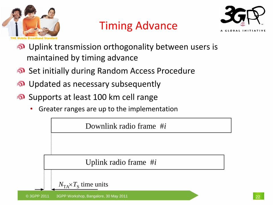
Timing Advance
Uplink transmission orthogonality between users is maintained by timing advance
Set initially during Random Access Procedure
Updated as necessary subsequently
Supports at least 100 km cell range• Greater ranges are up to the implementation
Downlink radio frame #i
Uplink radio frame #i
NTATS time units
22

THE Mobile Broadband Standard
© 3GPP 2011 3GPP Workshop, Bangalore, 30 May 2011
Uplink Power Control
Controls uplink power spectral density• Total uplink transmit power scales linearly with transmitted bandwidth
Fractional power control can compensate for all or part of path loss• Allows trade-off between intra-cell fairness and inter-cell interference
MCS-specific offsets may be applied
Closed-loop power control commands can fine-tune the power setting • Carried on PDCCH
• Individual commands in UL resource grants
• Group commands for groups of UEs
Separate power control for PUCCH and PUSCH
23

THE Mobile Broadband Standard
© 3GPP 2011 3GPP Workshop, Bangalore, 30 May 2011
UL Multi-Antenna transmission
Rel-8/9 supports:
• Switched antenna diversity• Closed-loop antenna switching supported by CRC masking on PBCH
• MU-MIMO• Different cyclic shifts of DM RS can be allocated to different UEs
24

THE Mobile Broadband Standard
© 3GPP 2011 3GPP Workshop, Bangalore, 30 May 2011
Contents
Introduction
Downlink Aspects for LTE Release 8
Uplink Aspects for LTE Release 8
Enhancements for LTE-Advanced (Release 10 and beyond)
25

THE Mobile Broadband Standard
© 3GPP 2011 3GPP Workshop, Bangalore, 30 May 2011
General Requirements
LTE-Advanced is an evolution of LTEAll relevant requirements of LTE are valid also for LTE-Advanced LTE-Advanced shall meet or exceed IMT-Advanced requirements within the ITU-R time plan• LTE-Advanced was approved as one of the IMT-Advanced RIT by ITU-R
Targets of LTE-Advanced are adopted as long term targets
26
Syste
m
perf
orm
ance
IMT-Advanced requirements and time plan
Rel-8 LTE
LTE-Advanced
targets
time

THE Mobile Broadband Standard
© 3GPP 2011 3GPP Workshop, Bangalore, 30 May 2011
Peak data rate• 1 Gbps data rate will be achieved by 4-by-4 MIMO and transmission
bandwidth wider than approximately 70 MHz
Peak spectrum efficiency• DL: Rel. 8 LTE satisfies IMT-Advanced requirement
• UL: Need to double from Release 8 to satisfy IMT-Advanced requirement
Rel. 8 LTE LTE-Advanced IMT-Advanced
Peak data rateDL 300 Mbps 1 Gbps
1 Gbps(*)
UL 75 Mbps 500 Mbps
Peak spectrum efficiency [bps/Hz]
DL 15 30 15
UL 3.75 15 6.75
*“100 Mbps for high mobility and 1 Gbps for low mobility” is one of the key features as written in
Circular Letter (CL)
System Performance Requirements for LTE-
Advanced
27
THE Mobile Broadband Standard
© 3GPP 2011 3GPP Workshop, Bangalore, 30 May 2011
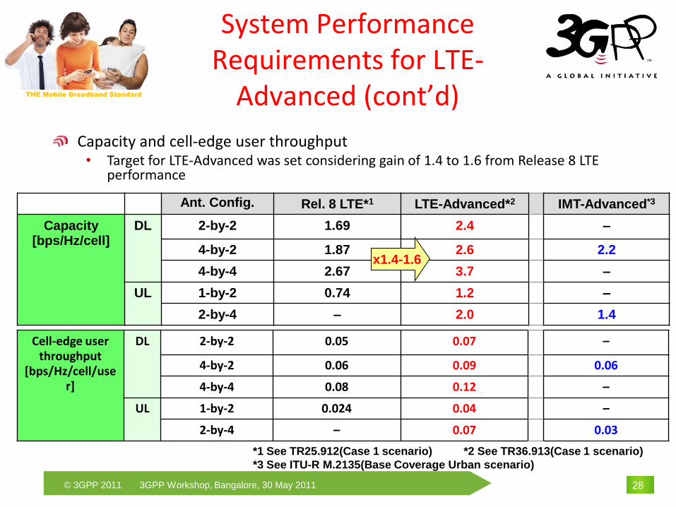
System Performance Requirements for LTE-
Advanced (cont’d)
Cell-edge user throughput
[bps/Hz/cell/user]
DL 2-by-2 0.05 0.07 –
4-by-2 0.06 0.09 0.06
4-by-4 0.08 0.12 –
UL 1-by-2 0.024 0.04 –
2-by-4 – 0.07 0.03
Ant. Config. Rel. 8 LTE*1 LTE-Advanced*2 IMT-Advanced*3
Capacity [bps/Hz/cell]
DL 2-by-2 1.69 2.4 –
4-by-2 1.87 2.6 2.2
4-by-4 2.67 3.7 –
UL 1-by-2 0.74 1.2 –
2-by-4 – 2.0 1.4
x1.4-1.6
*1 See TR25.912(Case 1 scenario) *2 See TR36.913(Case 1 scenario)
*3 See ITU-R M.2135(Base Coverage Urban scenario)
Capacity and cell-edge user throughput• Target for LTE-Advanced was set considering gain of 1.4 to 1.6 from Release 8 LTE
performance
28
THE Mobile Broadband Standard
© 3GPP 2011 3GPP Workshop, Bangalore, 30 May 2011
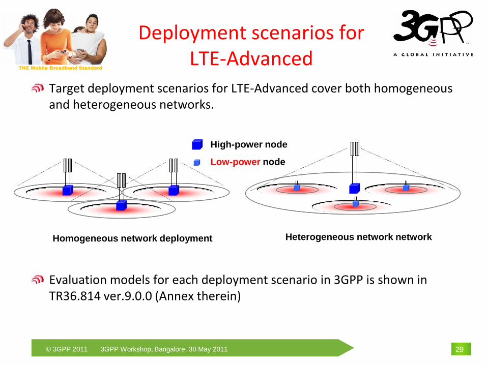
Deployment scenarios for LTE-Advanced
Target deployment scenarios for LTE-Advanced cover both homogeneous and heterogeneous networks.
Evaluation models for each deployment scenario in 3GPP is shown in TR36.814 ver.9.0.0 (Annex therein)
High-power node
Low-power node
Homogeneous network deployment Heterogeneous network network
29

THE Mobile Broadband Standard
© 3GPP 2011 3GPP Workshop, Bangalore, 30 May 2011
Major Work Items for Release 10 LTE in RAN1
Carrier aggregation for LTE
Enhanced multi-antenna downlink transmission for LTE
Uplink multiple antenna transmission for LTE
Relays for LTE
Enhanced ICIC for non-CA (carrier aggregation) based deployment of heterogeneous networks
30

THE Mobile Broadband Standard
© 3GPP 2011 3GPP Workshop, Bangalore, 30 May 2011
Wider bandwidth transmission using carrier aggregation for both DL and UL
Entire system bandwidth up to, e.g., 100 MHz, comprises multiple basic frequency blocks called component carriers (CCs)
Satisfy requirements for peak data rate
Each CC can be configured in a backward compatible way with Rel-8 LTE
Maintain backward compatibility with Rel-8 LTE
Carrier aggregation supports both contiguous and non-contiguous spectrum, and asymmetric bandwidth for FDD Achieve flexible spectrum usage
Frequency
System bandwidth,
e.g., 100 MHzCC, e.g., 20 MHz
Examples of
UE capabilities
• 100-MHz case
• 40-MHz case
• 20-MHz case
(Rel. 8 LTE)
Carrier Aggregation (CA)
31

THE Mobile Broadband Standard
© 3GPP 2011 3GPP Workshop, Bangalore, 30 May 2011
Extension up to 8-layer transmission• Increased from 4 layers in Rel-8/9 Satisfy the requirement for peak spectrum efficiency,
i.e., 30 bps/Hz
Additional reference signals (RS) specified:• Channel state information RS (CSI-RS) For downlink channel sounding Sparse, low overhead (configurable)
Density: 1 resource element (RE) per antenna port per PRB
• UE-specific demodulation RS (DM-RS) UE-specific DM-RS can be precoded, supporting non-codebook-based
precoding, applied 1-8-layer transmission, and enhanced
multi-user beamforming, such as zero forcing (ZF) DM RS pattern for higher numbers of layers is
extended from 2-layer format for transmissionmode 8 in Rel-9
Max. 8 streams
Enhanced Downlink Multi-antenna Transmission
Baseline StaggeredDMRS pattern
32

THE Mobile Broadband Standard
© 3GPP 2011 3GPP Workshop, Bangalore, 30 May 2011
Enhanced Downlink Multi-antenna Transmission
(Cont’d)
Enhanced Multi-user (MU) MIMO
MU-MIMO dimensionality
• Maximum spatial 4 layers
• Maximum 2 layers per user
CSI feedback enhancement using two matrix (W1, W2) feedback frame work is now being studied
• W1 targets wideband/long-term channel properties
• W2 targets frequency-selective/short-term time channel properties
• Matrix multiplication is used.
Enhanced
MU-MIMO
CSI
feedback
33

THE Mobile Broadband Standard
© 3GPP 2011 3GPP Workshop, Bangalore, 30 May 2011
UL transmit diversity for PUCCH to improve robustness in cell-edge
• Orthogonal resource transmit diversity is supported for PUCCH format 1 (Scheduling
request) 1a/1b (HARQ-Ack) when UE has two Tx antennas
the same modulation symbol from the uplink channel is transmitted from two
antenna ports, on two separate orthogonal resources.
SU-MIMO up to 4-stream transmission to satisfy the requirement for peak
spectrum efficiency, i.e., 15 bps/Hz
• Closed-loop codebook based precoding supported
Max. 4 streams
SU-MIMO up to 4 streams
Enhanced Uplink Multi-antenna Transmission
34

THE Mobile Broadband Standard
© 3GPP 2011 3GPP Workshop, Bangalore, 30 May 2011
Relay design target for Rel-10 is coverage extension
Supports cell deployments in areas where wired backhaul is not available or very expensive
“Type 1” relay
• Inband relaying: same carrier frequency for backhaul and access links
• Time division multiplexing of backaul and access links• Relay node (RN) creates a separate cell distinct from the donor cell• UE receives/transmits control signals for scheduling and HARQ from/to RN • RN appears as a Rel-8 LTE eNB to Rel-8 LTE UEs
“Type 1a” relay
• Outband relaying: different carrier frequency for backhaul from access link
Relaying for LTE
Relay node (RN)
UE
Macro (eNB)
Backhaul link Access link
35

THE Mobile Broadband Standard
© 3GPP 2011 3GPP Workshop, Bangalore, 30 May 2011
Conclusions
LTE Rel.8 is now in commercial service phase.
• 20 commercial LTE NW launched
• 208 operators in 80 countries investing in LTE
LTE-Advanced is a very flexible and advanced system
• Built on the established capabilities of the LTE Rel-8 and Rel-9 physical layer
• Further enhancements to exploit spectrum availability and advanced multi-antenna techniques
36

THE Mobile Broadband Standard
© 3GPP 2011 3GPP Workshop, Bangalore, 30 May 2011
Thank You
37
www.3gpp.org
More Information about 3GPP:
Sadayuki AbetaNTT DOCOMO