Embed Size (px)
Citation preview
LtFi: Cross-technology Communication for RRMbetween LTE-U and IEEE 802.11
Piotr Gawłowicz, Anatolij Zubow and Adam Wolisz{gawlowicz, zubow, wolisz}@tkn.tu-berlin.de
Technische Universitat Berlin, Germany
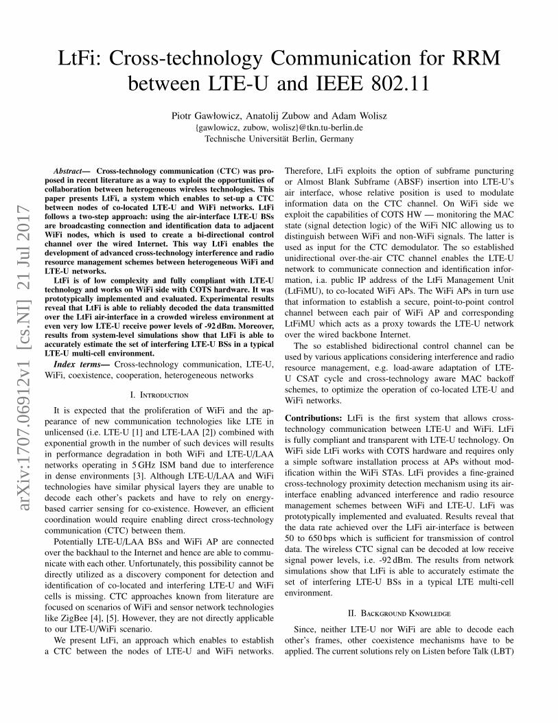
Abstract— Cross-technology communication (CTC) was pro-posed in recent literature as a way to exploit the opportunities ofcollaboration between heterogeneous wireless technologies. Thispaper presents LtFi, a system which enables to set-up a CTCbetween nodes of co-located LTE-U and WiFi networks. LtFifollows a two-step approach: using the air-interface LTE-U BSsare broadcasting connection and identification data to adjacentWiFi nodes, which is used to create a bi-directional controlchannel over the wired Internet. This way LtFi enables thedevelopment of advanced cross-technology interference and radioresource management schemes between heterogeneous WiFi andLTE-U networks.
LtFi is of low complexity and fully compliant with LTE-Utechnology and works on WiFi side with COTS hardware. It wasprototypically implemented and evaluated. Experimental resultsreveal that LtFi is able to reliably decoded the data transmittedover the LtFi air-interface in a crowded wireless environment ateven very low LTE-U receive power levels of -92 dBm. Moreover,results from system-level simulations show that LtFi is able toaccurately estimate the set of interfering LTE-U BSs in a typicalLTE-U multi-cell environment.
Index terms— Cross-technology communication, LTE-U,WiFi, coexistence, cooperation, heterogeneous networks
I. Introduction
It is expected that the proliferation of WiFi and the ap-pearance of new communication technologies like LTE inunlicensed (i.e. LTE-U [1] and LTE-LAA [2]) combined withexponential growth in the number of such devices will resultsin performance degradation in both WiFi and LTE-U/LAAnetworks operating in 5 GHz ISM band due to interferencein dense environments [3]. Although LTE-U/LAA and WiFitechnologies have similar physical layers they are unable todecode each other’s packets and have to rely on energy-based carrier sensing for co-existence. However, an efficientcoordination would require enabling direct cross-technologycommunication (CTC) between them.
Potentially LTE-U/LAA BSs and WiFi AP are connectedover the backhaul to the Internet and hence are able to commu-nicate with each other. Unfortunately, this possibility cannot bedirectly utilized as a discovery component for detection andidentification of co-located and interfering LTE-U and WiFicells is missing. CTC approaches known from literature arefocused on scenarios of WiFi and sensor network technologieslike ZigBee [4], [5]. However, they are not directly applicableto our LTE-U/WiFi scenario.
We present LtFi, an approach which enables to establisha CTC between the nodes of LTE-U and WiFi networks.
Therefore, LtFi exploits the option of subframe puncturingor Almost Blank Subframe (ABSF) insertion into LTE-U’sair interface, whose relative position is used to modulateinformation data on the CTC channel. On WiFi side weexploit the capabilities of COTS HW — monitoring the MACstate (signal detection logic) of the WiFi NIC allowing us todistinguish between WiFi and non-WiFi signals. The latter isused as input for the CTC demodulator. The so establishedunidirectional over-the-air CTC channel enables the LTE-Unetwork to communicate connection and identification infor-mation, i.a. public IP address of the LtFi Management Unit(LtFiMU), to co-located WiFi APs. The WiFi APs in turn usethat information to establish a secure, point-to-point controlchannel between each pair of WiFi AP and correspondingLtFiMU which acts as a proxy towards the LTE-U networkover the wired backbone Internet.
The so established bidirectional control channel can beused by various applications considering interference and radioresource management, e.g. load-aware adaptation of LTE-U CSAT cycle and cross-technology aware MAC backoff
schemes, to optimize the operation of co-located LTE-U andWiFi networks.
Contributions: LtFi is the first system that allows cross-technology communication between LTE-U and WiFi. LtFiis fully compliant and transparent with LTE-U technology. OnWiFi side LtFi works with COTS hardware and requires onlya simple software installation process at APs without mod-ification within the WiFi STAs. LtFi provides a fine-grainedcross-technology proximity detection mechanism using its air-interface enabling advanced interference and radio resourcemanagement schemes between WiFi and LTE-U. LtFi wasprototypically implemented and evaluated. Results reveal thatthe data rate achieved over the LtFi air-interface is between50 to 650 bps which is sufficient for transmission of controldata. The wireless CTC signal can be decoded at low receivesignal power levels, i.e. -92 dBm. The results from networksimulations show that LtFi is able to accurately estimate theset of interfering LTE-U BSs in a typical LTE multi-cellenvironment.
II. Background Knowledge
Since, neither LTE-U nor WiFi are able to decode eachother’s frames, other coexistence mechanisms have to beapplied. The current solutions rely on Listen before Talk (LBT)
arX
iv:1
707.
0691
2v1
[cs
.NI]
21
Jul 2
017
based on energy-based carrier sensing. This section gives abrief introduction into the relevant parts of the LTE-U andWiFi standards.
A. LTE-U
LTE-U is being specified by the LTE-U forum [1] as firstcellular solution for use of unlicensed band for the downlink(DL) traffic. The LTE carrier aggregation framework supportsutilization of the unlicensed band as a secondary cell in addi-tion to the licensed anchor serving as the primary cell [6]. TheLTE-U channel bandwidth is set to 20 MHz which correspondsto the smallest channel width in WiFi. LTE-U can be deployedin USA, China and India, where LBT is not required forunlicensed channel access.
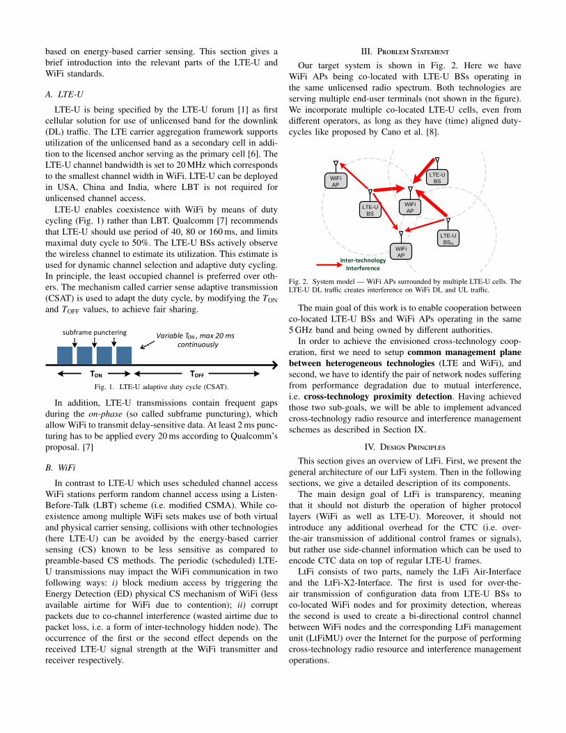
LTE-U enables coexistence with WiFi by means of dutycycling (Fig. 1) rather than LBT. Qualcomm [7] recommendsthat LTE-U should use period of 40, 80 or 160 ms, and limitsmaximal duty cycle to 50%. The LTE-U BSs actively observethe wireless channel to estimate its utilization. This estimate isused for dynamic channel selection and adaptive duty cycling.In principle, the least occupied channel is preferred over oth-ers. The mechanism called carrier sense adaptive transmission(CSAT) is used to adapt the duty cycle, by modifying the TONand TOFF values, to achieve fair sharing.
TON TOFF
subframe punctering Variable T , max 20 ms continuously
ON
Fig. 1. LTE-U adaptive duty cycle (CSAT).
In addition, LTE-U transmissions contain frequent gapsduring the on-phase (so called subframe puncturing), whichallow WiFi to transmit delay-sensitive data. At least 2 ms punc-turing has to be applied every 20 ms according to Qualcomm’sproposal. [7]
B. WiFi
In contrast to LTE-U which uses scheduled channel accessWiFi stations perform random channel access using a Listen-Before-Talk (LBT) scheme (i.e. modified CSMA). While co-existence among multiple WiFi sets makes use of both virtualand physical carrier sensing, collisions with other technologies(here LTE-U) can be avoided by the energy-based carriersensing (CS) known to be less sensitive as compared topreamble-based CS methods. The periodic (scheduled) LTE-U transmissions may impact the WiFi communication in twofollowing ways: i) block medium access by triggering theEnergy Detection (ED) physical CS mechanism of WiFi (lessavailable airtime for WiFi due to contention); ii) corruptpackets due to co-channel interference (wasted airtime due topacket loss, i.e. a form of inter-technology hidden node). Theoccurrence of the first or the second effect depends on thereceived LTE-U signal strength at the WiFi transmitter andreceiver respectively.
III. Problem Statement
Our target system is shown in Fig. 2. Here we haveWiFi APs being co-located with LTE-U BSs operating inthe same unlicensed radio spectrum. Both technologies areserving multiple end-user terminals (not shown in the figure).We incorporate multiple co-located LTE-U cells, even fromdifferent operators, as long as they have (time) aligned duty-cycles like proposed by Cano et al. [8].
LTE-U
BSN
LTE-U
BS
WiFi
AP
Inter-technology Interference
LTE-U
BS
WiFi
AP
WiFi
AP
Fig. 2. System model — WiFi APs surrounded by multiple LTE-U cells. TheLTE-U DL traffic creates interference on WiFi DL and UL traffic.
The main goal of this work is to enable cooperation betweenco-located LTE-U BSs and WiFi APs operating in the same5 GHz band and being owned by different authorities.
In order to achieve the envisioned cross-technology coop-eration, first we need to setup common management planebetween heterogeneous technologies (LTE and WiFi), andsecond, we have to identify the pair of network nodes sufferingfrom performance degradation due to mutual interference,i.e. cross-technology proximity detection. Having achievedthose two sub-goals, we will be able to implement advancedcross-technology radio resource and interference managementschemes as described in Section IX.
IV. Design Principles
This section gives an overview of LtFi. First, we present thegeneral architecture of our LtFi system. Then in the followingsections, we give a detailed description of its components.
The main design goal of LtFi is transparency, meaningthat it should not disturb the operation of higher protocollayers (WiFi as well as LTE-U). Moreover, it should notintroduce any additional overhead for the CTC (i.e. over-the-air transmission of additional control frames or signals),but rather use side-channel information which can be used toencode CTC data on top of regular LTE-U frames.
LtFi consists of two parts, namely the LtFi Air-Interfaceand the LtFi-X2-Interface. The first is used for over-the-air transmission of configuration data from LTE-U BSs toco-located WiFi nodes and for proximity detection, whereasthe second is used to create a bi-directional control channelbetween WiFi nodes and the corresponding LtFi managementunit (LtFiMU) over the Internet for the purpose of performingcross-technology radio resource and interference managementoperations.
LTE-U BS WiFi AP
Unidirectional CTC channel
Internetw
ired
wir
ed
Cross-technology RRM applications
1Broadcast public IP of
LtFiMU + Cell ID
LtFi Management
Unit
Bidirectional out-of-band control channel
3
air
air
Set-up CC2
Fig. 3. Overview of the system architecture of LtFi — using the air interface aLTE-U BS transmits configuration parameters which are used to set-up an out-of-band control channels with the corresponding LtFiMU over the Internet.
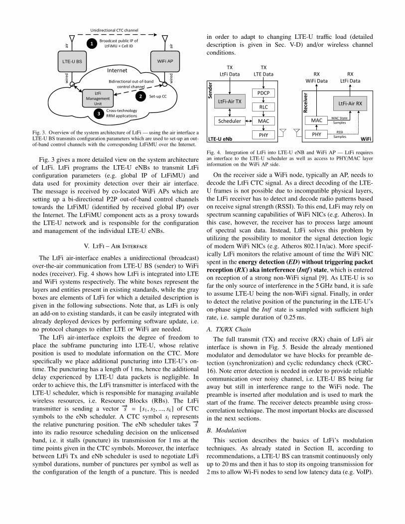
Fig. 3 gives a more detailed view on the system architectureof LtFi. LtFi programs the LTE-U eNBs to transmit LtFiconfiguration parameters (e.g. global IP of LtFiMU) anddata used for proximity detection over their air interface.The message is received by co-located WiFi APs which aresetting up a bi-directional P2P out-of-band control channelstowards the LtFiMU (identified by received global IP) overthe Internet. The LtFiMU component acts as a proxy towardsthe LTE-U network and is responsible for the configurationand management of the individual LTE-U eNBs.
V. LtFi – Air Interface
The LtFi air-interface enables a unidirectional (broadcast)over-the-air communication from LTE-U BS (sender) to WiFinodes (receiver). Fig. 4 shows how LtFi is integrated into LTEand WiFi systems respectively. The white boxes represent thelayers and entities present in existing standards, while the grayboxes are elements of LtFi for which a detailed description isgiven in the following subsections. Note that, as LtFi is onlyan add-on to existing standards, it can be easily integrated withalready deployed devices by performing software update, i.e.no protocol changes to either LTE or WiFi are needed.
The LtFi air-interface exploits the degree of freedom toplace the subframe puncturing into LTE-U, whose relativeposition is used to modulate information on the CTC. Morespecifically we place additional puncturing into LTE-U’s on-time. The puncturing has a length of 1 ms, hence the additionaldelay experienced by LTE-U data packets is negligible. Inorder to achieve this, the LtFi transmitter is interfaced with theLTE-U scheduler, which is responsible for managing availablewireless resources, i.e. Resource Blocks (RBs). The LtFitransmitter is sending a vector −→s = [s1, s2, ..., sk] of CTCsymbols to the eNb scheduler. A CTC symbol si representsthe relative puncturing position. The eNb scheduler takes −→sinto its radio resource scheduling decision on the unlicensedband, i.e. it stalls (puncture) its transmission for 1 ms at thetime points given in the CTC symbols. Moreover, the interfacebetween LtFi Tx and eNb scheduler is used to negotiate LtFisymbol durations, number of punctures per symbol as well asthe configuration of the length of a puncture. This is needed
in order to adapt to changing LTE-U traffic load (detaileddescription is given in Sec. V-D) and/or wireless channelconditions.
PDCP
RLC
MAC
PHY
Scheduler
LtFi-Air TX
TX LTE Data
TX LtFi Data
Sen
de
r
LTE-U eNb
MAC
PHY
RX WiFi Data
LtFi-Air RX
WiFi
Rec
eiv
er
MAC State Samples
RSSI Samples
RX LtFi Data
Fig. 4. Integration of LtFi into LTE-U eNB and WiFi AP — LtFi requiresan interface to the LTE-U scheduler as well as access to PHY/MAC layerinformation on the WiFi AP side.
On the receiver side a WiFi node, typically an AP, needs todecode the LtFi CTC signal. As a direct decoding of the LTE-U frames is not possible due to incompatible physical layers,the LtFi receiver has to detect and decode radio patterns basedon receive signal strength (RSSI). To this end, LtFi may rely onspectrum scanning capabilities of WiFi NICs (e.g. Atheros). Inthis case, however, the receiver has to process large amountof spectral scan data. Instead, LtFi solves this problem byutilizing the possibility to monitor the signal detection logicof modern WiFi NICs (e.g. Atheros 802.11n/ac). More specif-ically LtFi monitors the relative amount of time the WiFi NICspent in the energy detection (ED) without triggering packetreception (RX) aka interference (Intf ) state, which is enteredon reception of a strong non-WiFi signal [9]. As LTE-U is sofar the only source of interference in the 5 GHz band, it is safeto assume LTE-U being the non-WiFi signal. Finally, in orderto detect the relative position of the puncturing in the LTE-U’son-phase signal the Intf state is sampled with sufficient highrate, i.e. sample duration of 0.25 ms.
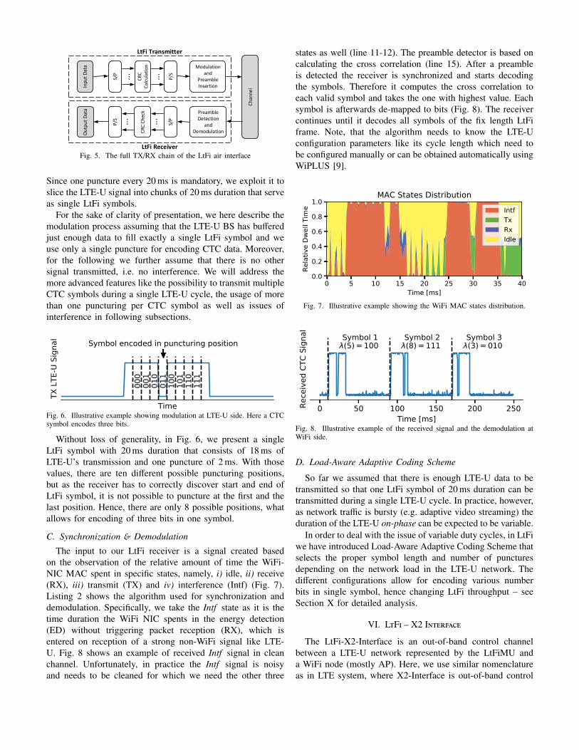
A. TX/RX Chain
The full transmit (TX) and receive (RX) chain of LtFi airinterface is shown in Fig. 5. Beside the already mentionedmodulator and demodulator we have blocks for preamble de-tection (synchronization) and cyclic redundancy check (CRC-16). Note error detection is needed in order to provide reliablecommunication over noisy channel, i.e. LTE-U BS being faraway but still in interference range to the WiFi node. Thepreamble is inserted after modulation and is used to mark thestart of the frame. The receiver detects preamble using cross-correlation technique. The most important blocks are discussedin the next sections.
B. Modulation
This section describes the basics of LtFi’s modulationtechniques. As already stated in Section II, according torecommendations, a LTE-U BS can transmit continuously onlyup to 20 ms and then it has to stop its ongoing transmission for2 ms to allow Wi-Fi nodes to send low latency data (e.g. VoIP).
...
...
Ch
anne
lInpu
t D
ata
CR
C
Cal
cula
tion
P/S
LtFi Transmitter
Modulation and
PreambleInsertion
Ou
tpu
t D
ata
CR
C C
hec
kLtFi Receiver
S/P
S/P
P/S ......
Preamble Detection
andDemodulation
Fig. 5. The full TX/RX chain of the LtFi air interface
Since one puncture every 20 ms is mandatory, we exploit it toslice the LTE-U signal into chunks of 20 ms duration that serveas single LtFi symbols.
For the sake of clarity of presentation, we here describe themodulation process assuming that the LTE-U BS has bufferedjust enough data to fill exactly a single LtFi symbol and weuse only a single puncture for encoding CTC data. Moreover,for the following we further assume that there is no othersignal transmitted, i.e. no interference. We will address themore advanced features like the possibility to transmit multipleCTC symbols during a single LTE-U cycle, the usage of morethan one puncturing per CTC symbol as well as issues ofinterference in following subsections.
Time
TX L
TE-U
Sig
nal Symbol encoded in puncturing position
000
001
010
011
100
101
110
111
Fig. 6. Illustrative example showing modulation at LTE-U side. Here a CTCsymbol encodes three bits.
Without loss of generality, in Fig. 6, we present a singleLtFi symbol with 20 ms duration that consists of 18 ms ofLTE-U’s transmission and one puncture of 2 ms. With thosevalues, there are ten different possible puncturing positions,but as the receiver has to correctly discover start and end ofLtFi symbol, it is not possible to puncture at the first and thelast position. Hence, there are only 8 possible positions, whatallows for encoding of three bits in one symbol.
C. Synchronization & Demodulation
The input to our LtFi receiver is a signal created basedon the observation of the relative amount of time the WiFi-NIC MAC spent in specific states, namely, i) idle, ii) receive(RX), iii) transmit (TX) and iv) interference (Intf) (Fig. 7).Listing 2 shows the algorithm used for synchronization anddemodulation. Specifically, we take the Intf state as it is thetime duration the WiFi NIC spents in the energy detection(ED) without triggering packet reception (RX), which isentered on reception of a strong non-WiFi signal like LTE-U. Fig. 8 shows an example of received Intf signal in cleanchannel. Unfortunately, in practice the Intf signal is noisyand needs to be cleaned for which we need the other three
states as well (line 11-12). The preamble detector is based oncalculating the cross correlation (line 15). After a preambleis detected the receiver is synchronized and starts decodingthe symbols. Therefore it computes the cross correlation toeach valid symbol and takes the one with highest value. Eachsymbol is afterwards de-mapped to bits (Fig. 8). The receivercontinues until it decodes all symbols of the fix length LtFiframe. Note, that the algorithm needs to know the LTE-Uconfiguration parameters like its cycle length which need tobe configured manually or can be obtained automatically usingWiPLUS [9].
0 5 10 15 20 25 30 35 40Time [ms]
0.0
0.2
0.4
0.6
0.8
1.0
Rela
tive
Dwel
l Tim
e
MAC States DistributionIntfTxRxIdle
Fig. 7. Illustrative example showing the WiFi MAC states distribution.
0 50 100 150 200 250Time [ms]
Rece
ived
CTC
Sig
nal
Symbol 1(5) = 100
Symbol 2(8) = 111
Symbol 3(3) = 010
Fig. 8. Illustrative example of the received signal and the demodulation atWiFi side.
D. Load-Aware Adaptive Coding Scheme
So far we assumed that there is enough LTE-U data to betransmitted so that one LtFi symbol of 20 ms duration can betransmitted during a single LTE-U cycle. In practice, however,as network traffic is bursty (e.g. adaptive video streaming) theduration of the LTE-U on-phase can be expected to be variable.
In order to deal with the issue of variable duty cycles, in LtFiwe have introduced Load-Aware Adaptive Coding Scheme thatselects the proper symbol length and number of puncturesdepending on the network load in the LTE-U network. Thedifferent configurations allow for encoding various numberbits in single symbol, hence changing LtFi throughput – seeSection X for detailed analysis.
VI. LtFi – X2 Interface
The LtFi-X2-Interface is an out-of-band control channelbetween a LTE-U network represented by the LtFiMU anda WiFi node (mostly AP). Here, we use similar nomenclatureas in LTE system, where X2-Interface is out-of-band control
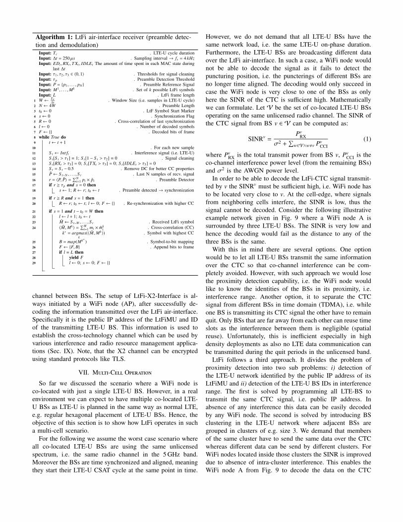
Algorithm 1: LtFi air-interface receiver (preamble detec-tion and demodulation)
Input: Tc . LTE-U cycle durationInput: ∆t = 250 µs . Sampling interval → fs = 4 kHzInput: EDt ,RXt ,T Xt , IDLEt The amount of time spent in each MAC state during
last ∆tInput: τ1, τ2, τ3 ∈ 〈0, 1〉 . Thresholds for signal cleaningInput: τp . Preamble Detection ThresholdInput: P = {p1, . . . , pN } . Preamble Reference SignalInput: M1, . . . ,Mk . Set of k possible LtFi symbolsInput: L . LtFi frame length
1 W ← Tc∆t . Window Size (i.e. samples in LTE-U cycle)
2 N ← 4W . Preamble Length3 t0 ← 0 . LtF Symbol Start Marker4 s← 0 . Synchronization Flag5 R← 0 . Cross-correlation of last synchronization6 l← 0 . Number of decoded symbols7 F ← {} . Decoded bits of frame8 while True do9 t ← t + 1
10 . For each new sample11 S t ← Int ft . Interference signal (i.e. LTE-U)12 S t[S t > τ1] = 1; S t[1 − S t > τ2] = 0 . Signal cleaning13 S t[RXt > τ3] = 0; S t[T Xt > τ3] = 0; S t[IDLEt > τ3] = 014 S t = S t − 0.5 . Remove DC for better CC properties15 P← S t−N , . . . , S t . Last N samples of recv. signal16 r = 〈P, P〉 =
∑Ni=1 pi × pi . Preamble Detector
17 if r ≥ τp and s = 0 then18 s← 1; R← r; t0 ← t . Preamble detected → synchronization
19 if r ≥ R and s = 1 then20 R← r; t0 ← t; l← 0; F ← {} . Re-synchronization with higher CC
21 if s = 1 and t − t0 = W then22 l← l + 1; t0 ← t23 M ← S t−W , . . . , S t . Received LtFi symbol24 〈M,Mk〉 =
∑Wi=1 mi × mk
i . Cross-correlation (CC)k∗ = argmax
k(〈M,Mk〉) . Symbol with highest CC
25 B = map(Mk∗ ) . Symbol-to-bit mapping26 F ← {F, B} . Append bits to frame27 if l = L then28 yield F29 l← 0; s← 0; F ← {}
channel between BSs. The setup of LtFi-X2-Interface is al-ways initiated by a WiFi node (AP), after successfully de-coding the information transmitted over the LtFi air-interface.Specifically it is the public IP address of the LtFiMU and IDof the transmitting LTE-U BS. This information is used toestablish the cross-technology channel which can be used byvarious interference and radio resource management applica-tions (Sec. IX). Note, that the X2 channel can be encryptedusing standard protocols like TLS.
VII. Multi-Cell Operation
So far we discussed the scenario where a WiFi node isco-located with just a single LTE-U BS. However, in a realenvironment we can expect to have multiple co-located LTE-U BSs as LTE-U is planned in the same way as normal LTE,e.g. regular hexagonal placement of LTE-U BSs. Hence, theobjective of this section is to show how LtFi operates in sucha multi-cell scenario.
For the following we assume the worst case scenario whereall co-located LTE-U BSs are using the same unlicensedspectrum, i.e. the same radio channel in the 5 GHz band.Moreover the BSs are time synchronized and aligned, meaningthey start their LTE-U CSAT cycle at the same point in time.
However, we do not demand that all LTE-U BSs have thesame network load, i.e. the same LTE-U on-phase duration.Furthermore, the LTE-U BSs are broadcasting different dataover the LtFi air-interface. In such a case, a WiFi node wouldnot be able to decode the signal as it fails to detect thepuncturing position, i.e. the puncterings of different BSs areno longer time aligned. The decoding would only succeed incase the WiFi node is very close to one of the BSs as onlyhere the SINR of the CTC is sufficient high. Mathematicallywe can formulate. Let V be the set of co-located LTE-U BSsoperating on the same unlicensed radio channel. The SINR ofthe CTC signal from BS v ∈ V can be computed as:
SINRv =Pv
RX
σ2 +∑
w∈V∧w,v PvCCI
(1)
where PvRX is the total transmit power from BS v, Pv
CCI is theco-channel interference power level (from the remaining BSs)and σ2 is the AWGN power level.
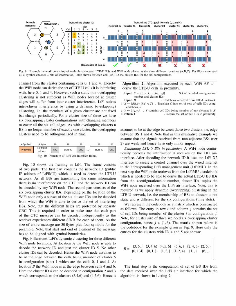
In order to be able to decode the LtFi-CTC signal transmit-ted by v the SINRv must be sufficient high, i.e. WiFi node hasto be located very close to v. At the cell-edge, where signalsfrom neighboring cells interfere, the SINR is low, thus thesignal cannot be decoded. Consider the following illustrativeexample network given in Fig. 9 where a WiFi node A issurrounded by three LTE-U BSs. The SINR is very low andhence the decoding would fail as the distance to any of thethree BSs is the same.
With this in mind there are several options. One optionwould be to let all LTE-U BSs transmit the same informationover the CTC so that co-channel interference can be com-pletely avoided. However, with such approach we would losethe proximity detection capability, i.e. the WiFi node wouldlike to know the identities of the BSs in its proximity, i.e.interference range. Another option, it to separate the CTCsignal from different BSs in time domain (TDMA), i.e. whileone BS is transmitting its CTC signal the other have to remainquit. Only BSs that are far away from each other can reuse timeslots as the interference between them is negligible (spatialreuse). Unfortunately, this is inefficient especially in highdensity deployments as also no LTE data communication canbe transmitted during the quit periods in the unlicensed band.
LtFi follows a third approach. It divides the problem ofproximity detection into two sub problems: i) detection ofthe LTE-U network identified by the public IP address of itsLtFiMU and ii) detection of the LTE-U BS IDs in interferencerange. The first is solved by programming all LTE-BS totransmit the same CTC signal, i.e. public IP address. Inabsence of any interference this data can be easily decodedby any WiFi node. The second is solved by introducing BSclustering in the LTE-U network where adjacent BSs aregrouped in clusters of e.g. size 3. We demand that membersof the same cluster have to send the same data over the CTCwhereas different data can be send by different clusters. ForWiFi nodes located inside those clusters the SINR is improveddue to absence of intra-cluster interference. This enables theWiFi node A from Fig. 9 to decode the data on the CTC
4
5
0.
1 5
Cel
l ID
:
2 2 1
Network ID Cluster #1 Cluster #2 Cluster #3 Cluster #4 Cluster #5 Cluster #6
1.
1 5 5 5 5
4.
1 5 4 5 4
5 1
1
2
Transmitted CTC signal (for cells 0, 1 and 4):Transmitted cluster ID:
5 5 2 2 1 1 5 5 5 5 5 2 7 7 5 5 4 4 4 4 1 1 1 1 5 4 4 5 4 1 6 6 4 4 4 4 4 4 4 4 3 0
Cellslot
0123456
1 2 3 4 5 6
6
Example network:
0
1
2
3
4
5
WiFi
A
B
C
Network ID: 1
Decodeable at pos. A:
Fig. 9. Example network consisting of multiple co-located LTE-U BSs and WiFi node placed at the three different locations (A,B,C). For illustration eachCTC symbol encodes 3 bits of information. Table shows for each cell (BS) ID the cluster IDs for the six configurations.
channel from the cluster containing cells 0, 1 and 4. Therebythe WiFi node can derive the set of LTE-U cells it is interferingwith, here 0, 1 and 4. However, such a static non-overlappingclustering is not sufficient as WiFi nodes located at clusteredges will suffer from inter-cluster interference. LtFi solvesinter-cluster interference by using a dynamic (overlapping)clustering, i.e. the members of a given cluster are not fixedbut change periodically. For a cluster size of three we havesix overlapping cluster configurations with changing membersto cover all the six cell-edges. As with overlapping clusters aBS is no longer member of exactly one cluster, the overlappingclusters need to be orthogonalized in time.
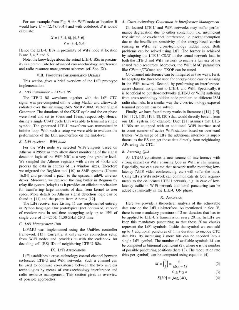
4 Symbols 4 Bytes 2B 2B 2B
Preamble ...
2B 2B
LtFiMU IP address
CRC CRC CRC1:CLS ID 6:CLS ID
Fig. 10. Structure of LtFi Air-Interface frame.
Fig. 10 shows the framing in LtFi. The frame consistsof two parts. The first part contains the network ID (publicIP address of LtFiMU) which is used to detect the LTE-Unetwork. As all BSs are transmitting the same informationthere is no interference on the CTC and the network ID canbe decoded by any WiFi node. The second part consists of thesix overlapping cluster IDs. Depending on the location of theWiFi node only a subset of the six cluster IDs can be decodedfrom which the WiFi is able to derive the set of interferingBSs. Note, that the different fields are protected by separateCRC. This is required in order to make sure that each partof the CTC message can be decoded independently as thereceiver experiences different SINR for each of them. As thesize of entire message are 30 Bytes plus four symbols for thepreamble. Note, that start and end of element of the messagehas to be aligned with symbol boundaries.
Fig. 9 illustrates LtFi’s dynamic clustering for three differentWiFi node locations. At location A the WiFi node is able todecode the network ID and just the cluster ID 5. No othercluster IDs can be decoded. Hence the WiFi node assumes tobe at the edge between the cells being member of cluster 5in configuration (slot) 1 which are the cells 0, 1 and 4. Atlocation B the WiFi node is at the edge between cells 4 and 6.Here the cluster ID 4 can be decoded in configuration 2 and 3which corresponds to the clusters (3,4,6) and (4,5,6). Hence it
Algorithm 2: Algorithm executed by each WiFi AP toderive the LTE-U cells in proximity.
Input: C = {(i1, c1), . . . , (in, cm)} . Set of decoded configurationnumber and cluster IDs
Input: B . Codebook received from LTE-U network1 X ← {B(i, c), (i, c) ∈ C} . Translate C into set of sets of cells IDs using
codebook B2 Y ←
⋃A∈X A . Y contains cell IDs being member of any element in X
3 return Y . Return the set of cell IDs in proximity
assumes to be at the edge between those two clusters, i.e. edgebetween BS 1 and 4. Note that in this illustrative example weassume that the signals received from non-adjacent BSs (tier2) are weak and hence have only minor impact.
Estimating LTE-U BSs in proximity: A WiFi node contin-uously decodes the information it receives on the LtFi air-interface. After decoding the network ID it uses the LtFi-X2interface to create a control channel over the wired Internetto the corresponding LtFi management unit (LtFiMU). In thenext step the WiFi node retrieves from the LtFiMU a codebookwhich is needed to be able to derive the actual LTE-U BS IDsfrom the <configuration/slot number, cluster ID> tuples theWiFi node received over the LtFi air-interface. Note, this isrequired as we apply dynamic (overlapping) clustering in theLTE-U network, i.e. the membership of BSs to clusters is notstatic and is different for the six configurations (time slots).
We represent the codebook as a matrix which is constructedas follows. The entry in row i and column j contains the setof cell IDs being member of the cluster i in configuration j.Note, for cluster size of three we need six overlapping clusterconfiguration, hence j ∈ (1, 6). The matrix shown below isthe codebook for the example given in Fig. 9. Here only theentries for the clusters with ID 4 and 5 are shown:
B =
...
{3, 6, } {3, 4, 6} {4, 5, 6} {5, 6, } {2, 4, 5} {2, 5, }{0, 1, 4} {0, 1, } {1, 2, } {1, 2, 4} {1, , } {6, , }
...
The final step is the computation of set of BS IDs from
the data received over the LtFi air interface for which thealgorithm is shown in Listing 2.
For our example from Fig. 9 the WiFi node at location Bwould have C = {(2, 4), (3, 4)} and with codebook B it wouldcalculate:
X = {{3, 4, 6}, {4, 5, 6}}Y = {3, 4, 5, 6}
Hence the LTE-U BSs in proximity of WiFi node at locationB are 3, 4, 5 and 6.
Note, the knowledge about the actual LTE-U BSs in proxim-ity is a prerequisite for advanced cross-technology interferenceand radio resource management schemes (cf. Sec. IX).
VIII. Prototype Implementation DetailsThis section gives a brief overview of the LtFi prototype
implementation.
A. LtFi transmitter – LTE-U BSThe LTE-U BS waveform together with the LtFi CTC
signal was pre-computed offline using Matlab and afterwardsradiated over the air using R&S SMBV100A Vector SignalGenerator. The durations of the CSAT cycle and the on phasewere fixed and set to 80 ms and 19 ms, respectively. Hence,during a single CSAT cycle LtFi was able to transmit a singlesymbol. The generated LTE-U waveform was transmitted ininfinite loop. With such a setup we were able to evaluate theperformance of the LtFi air-interface on the link-level.
B. LtFi receiver – WiFi nodeFor the WiFi node we selected WiFi chipsets based on
Atheros AR95xx as they allow direct monitoring of the signaldetection logic of the WiFi NIC at a very fine granular level.We sampled the Atheros registers with a rate of 4 kHz andprocess the data in chunks of 1 s window sizes. Thereforewe migrated the RegMon tool [10] to SMP systems (Ubuntu16.04) and provided a patch to the upstream ath9k wirelessdriver. Moreover, we replaced the ring buffer in Regmon byrelay file system (relayfs) as it provides an efficient mechanismfor transferring large amounts of data from kernel to userspace. More details on Atheros signal detection logic can befound in [11] and the patent from Atheros [12].
The LtFi receiver (see Listing 1) was implemented entirelyin Python language. Our prototypical (not optimized) versionof receiver runs in real-time occupying only up to 15% ofsingle core of i5-4250U (1.30 GHz) CPU time.
C. LtFi Management UnitLtFiMU was implemented using the UniFlex controller
framework [13]. Currently, it only serves connection setupfrom WiFi nodes and provides it with the codebook fordecoding cell (BS) IDs of neighboring LTE-U BSs.
IX. LtFi ApplicationsLtFi establishes a cross-technology control channel between
co-located LTE-U and WiFi networks. Such a channel canbe used to optimize co-existence between the two wirelesstechnologies by means of cross-technology interference andradio resource management. This section gives an overviewof possible approaches.
A. Cross-technology Contention & Interference Management
Co-located LTE-U and WiFi networks may suffer perfor-mance degradation due to either contention, i.e. insufficientfree airtime, or co-channel interference, i.e. packet corruptiondue to the insufficient sensitivity of the energy-based carriersensing in WiFi, i.e. cross-technology hidden node. Bothproblems can be solved using LtFi. The former is achievedby adapting the LTE-U CSAT to the actual network load inboth the LTE-U and WiFi network to enable a fair use of theshared radio resources. Moreover, the WiFi MAC parameterslike CWmin/CWmax and TXOP can be tuned.
Co-channel interference can be mitigated in two ways. First,by adapting the threshold used for energy-based carrier sensingin the WiFi network. Second, by performing an interference-aware channel assignment to LTE-U and WiFi. Specifically, itis beneficial to put those networks (LTE-U or WiFi) sufferingfrom cross-technology hidden node problem on different ISMradio channels. In a similar way the cross-technology exposedterminal problem can be solved.
Finally, we have found many works in literature ( [14], [15],[16], [17], [18], [19], [8], [20]) that would directly benefit fromour LtFi system. For example, Duet [21] assumes that LTE-U BSs are equipped with an additional WiFi interface usedto count number of active WiFi stations based on overheardframes. With usage of LtFi the additional interface is super-fluous, as the BS can get those data directly from neighboringAPs using the CTC.
B. Assuring QoS
As LTE-U constitutes a new source of interference withstrong impact on WiFi ensuring QoS in WiFi is challenging.Especially, we can assume that network traffic requiring low-latency (VoIP, video conferencing, etc.) will suffer the most.Using LtFi a WiFi network can communicate its QoS require-ments to the co-located LTE-U network, e.g. in case of low-latency traffic in WiFi network additional puncturing can beadded dynamically in the LTE-U ON phase.
X. AnalyticsHere we provide a theoretical analysis of the achievable
data rate on the LtFi air-interface. As mentioned in Sec. V,there is one mandatory puncture of 2 ms duration that has tobe applied to LTE-U’s transmission every 20 ms. In LtFi wekeep this mandatory puncturing so that those 20 ms chunksrepresent the LtFi symbols. Inside the symbol we can addup to k additional punctures of 1 ms duration to encode CTCdata bits. By increasing k more bits can be encoded into asingle LtFi symbol. The number of available symbols M canbe computed as binomial coefficient (2), where n is the numberof possible puncturing positions (here 18). The modulation rate(bits per symbol) can be computed using equation (4):
M =
(nk
)=
n!k!(n − k)
(2)
0 ≤ k ≤ n (3)K[bit] = blog2(M)c (4)
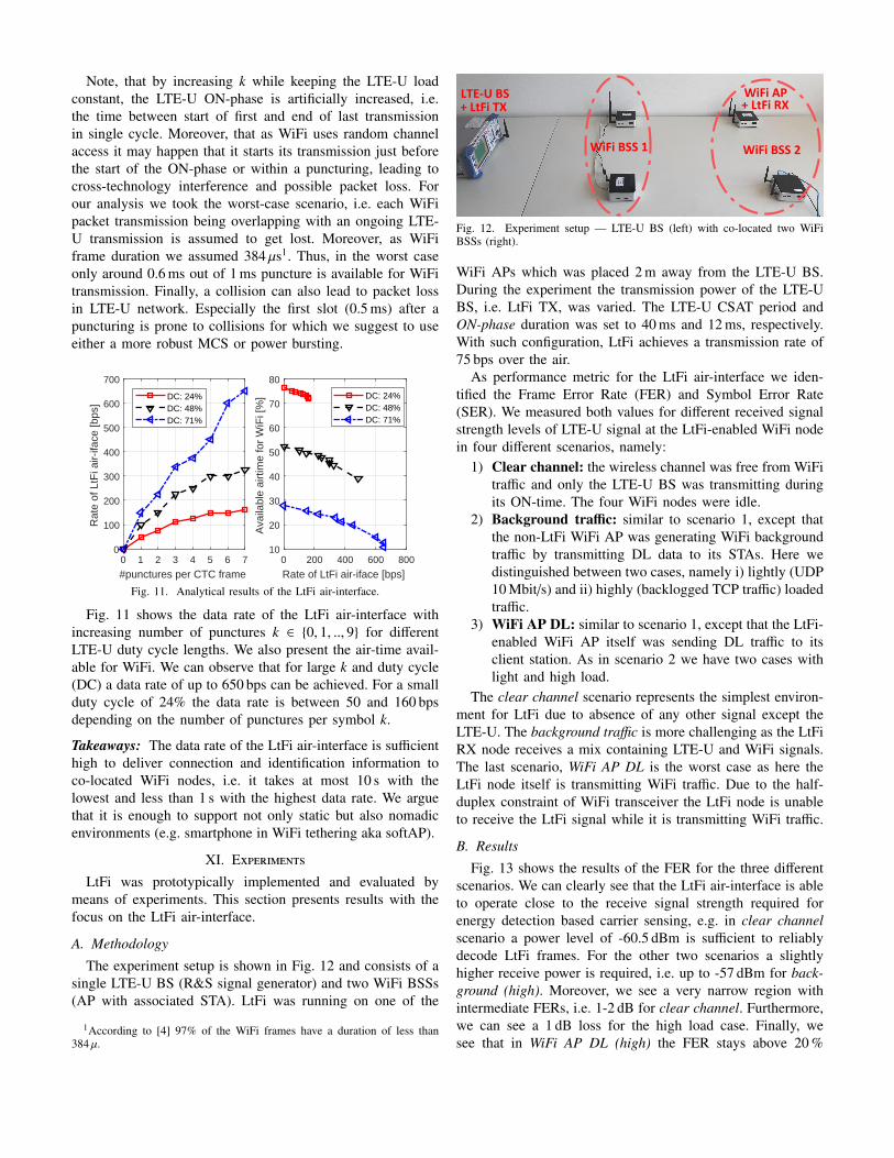
Note, that by increasing k while keeping the LTE-U loadconstant, the LTE-U ON-phase is artificially increased, i.e.the time between start of first and end of last transmissionin single cycle. Moreover, that as WiFi uses random channelaccess it may happen that it starts its transmission just beforethe start of the ON-phase or within a puncturing, leading tocross-technology interference and possible packet loss. Forour analysis we took the worst-case scenario, i.e. each WiFipacket transmission being overlapping with an ongoing LTE-U transmission is assumed to get lost. Moreover, as WiFiframe duration we assumed 384 µs1. Thus, in the worst caseonly around 0.6 ms out of 1 ms puncture is available for WiFitransmission. Finally, a collision can also lead to packet lossin LTE-U network. Especially the first slot (0.5 ms) after apuncturing is prone to collisions for which we suggest to useeither a more robust MCS or power bursting.
0 1 2 3 4 5 6 7
#punctures per CTC frame
0
100
200
300
400
500
600
700
Rat
e of
LtF
i air-
iface
[bps
]
DC: 24%DC: 48%DC: 71%
0 200 400 600 800
Rate of LtFi air-iface [bps]
10
20
30
40
50
60
70
80
Ava
ilabl
e ai
rtim
e fo
r W
iFi [
%] DC: 24%
DC: 48%DC: 71%
Fig. 11. Analytical results of the LtFi air-interface.
Fig. 11 shows the data rate of the LtFi air-interface withincreasing number of punctures k ∈ {0, 1, .., 9} for differentLTE-U duty cycle lengths. We also present the air-time avail-able for WiFi. We can observe that for large k and duty cycle(DC) a data rate of up to 650 bps can be achieved. For a smallduty cycle of 24% the data rate is between 50 and 160 bpsdepending on the number of punctures per symbol k.
Takeaways: The data rate of the LtFi air-interface is sufficienthigh to deliver connection and identification information toco-located WiFi nodes, i.e. it takes at most 10 s with thelowest and less than 1 s with the highest data rate. We arguethat it is enough to support not only static but also nomadicenvironments (e.g. smartphone in WiFi tethering aka softAP).
XI. Experiments
LtFi was prototypically implemented and evaluated bymeans of experiments. This section presents results with thefocus on the LtFi air-interface.
A. Methodology
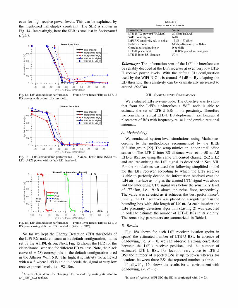
The experiment setup is shown in Fig. 12 and consists of asingle LTE-U BS (R&S signal generator) and two WiFi BSSs(AP with associated STA). LtFi was running on one of the
1According to [4] 97% of the WiFi frames have a duration of less than384 µ.
WiFi BSS 1 WiFi BSS 2
LTE-U BS+ LtFi TX
WiFi AP+ LtFi RX
Fig. 12. Experiment setup — LTE-U BS (left) with co-located two WiFiBSSs (right).
WiFi APs which was placed 2 m away from the LTE-U BS.During the experiment the transmission power of the LTE-UBS, i.e. LtFi TX, was varied. The LTE-U CSAT period andON-phase duration was set to 40 ms and 12 ms, respectively.With such configuration, LtFi achieves a transmission rate of75 bps over the air.
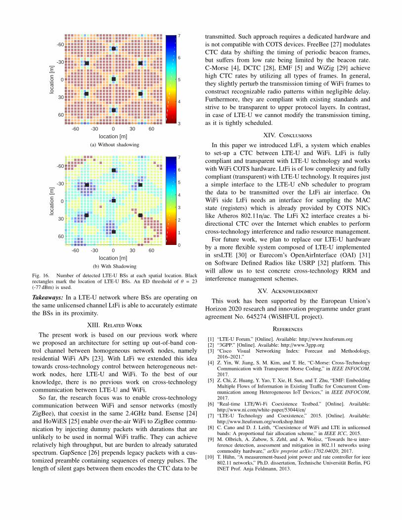
As performance metric for the LtFi air-interface we iden-tified the Frame Error Rate (FER) and Symbol Error Rate(SER). We measured both values for different received signalstrength levels of LTE-U signal at the LtFi-enabled WiFi nodein four different scenarios, namely:
1) Clear channel: the wireless channel was free from WiFitraffic and only the LTE-U BS was transmitting duringits ON-time. The four WiFi nodes were idle.
2) Background traffic: similar to scenario 1, except thatthe non-LtFi WiFi AP was generating WiFi backgroundtraffic by transmitting DL data to its STAs. Here wedistinguished between two cases, namely i) lightly (UDP10 Mbit/s) and ii) highly (backlogged TCP traffic) loadedtraffic.
3) WiFi AP DL: similar to scenario 1, except that the LtFi-enabled WiFi AP itself was sending DL traffic to itsclient station. As in scenario 2 we have two cases withlight and high load.
The clear channel scenario represents the simplest environ-ment for LtFi due to absence of any other signal except theLTE-U. The background traffic is more challenging as the LtFiRX node receives a mix containing LTE-U and WiFi signals.The last scenario, WiFi AP DL is the worst case as here theLtFi node itself is transmitting WiFi traffic. Due to the half-duplex constraint of WiFi transceiver the LtFi node is unableto receive the LtFi signal while it is transmitting WiFi traffic.
B. Results
Fig. 13 shows the results of the FER for the three differentscenarios. We can clearly see that the LtFi air-interface is ableto operate close to the receive signal strength required forenergy detection based carrier sensing, e.g. in clear channelscenario a power level of -60.5 dBm is sufficient to reliablydecode LtFi frames. For the other two scenarios a slightlyhigher receive power is required, i.e. up to -57 dBm for back-ground (high). Moreover, we see a very narrow region withintermediate FERs, i.e. 1-2 dB for clear channel. Furthermore,we can see a 1 dB loss for the high load case. Finally, wesee that in WiFi AP DL (high) the FER stays above 20 %
even for high receive power levels. This can be explained bythe mentioned half-duplex constraint. The SER is shown inFig. 14. Interestingly, here the SER is smallest in background(light).
-64 -63 -62 -61 -60 -59 -58 -57 -56 -55LTE-U Rx Power at WiFi [dBm]
0
0.2
0.4
0.6
0.8
1
Fra
me
Err
or R
ate
[%]
Frame Error Rate
clear channelbackground (light)background (high)WiFi AP DL (light)WiFi AP DL (high)
Fig. 13. LtFi demodulator performance — Frame Error Rate (FER) vs. LTE-URX power with default ED threshold.
-64 -63 -62 -61 -60 -59 -58 -57 -56 -55LTE-U Rx Power at WiFi [dBm]
0
0.2
0.4
0.6
0.8
1
Sym
bol E
rror
Rat
e [%
]
Symbol Error Rate
clear channelbackground (light)background (high)WiFi AP DL (light)WiFi AP DL (high)
Fig. 14. LtFi demodulator performance — Symbol Error Rate (SER) vs.LTE-U RX power with default ED threshold.
-100 -95 -90 -85 -80 -75 -70 -65 -60 -55LTE-U Rx Power at WiFi [dBm]
0
0.2
0.4
0.6
0.8
1
Fra
me
Err
or R
ate
[%]
Frame Error Rate (clear channel)
=3=12=20=28 (default)
noisefloor
Fig. 15. LtFi demodulator performance — Frame Error Rate (FER) vs. LTE-URX power using different ED thresholds (Atheros NIC).
So far we kept the Energy Detection (ED) thresholds ofthe LtFi RX node constant at its default configuration, i.e. asset by the ATH9k driver. Next, Fig. 15 shows the FER for theclear channel scenario for different ED values2. Note, the blackcurve (θ = 28) corresponds to the default configuration usedin the Atheros WiFi NIC. The highest sensitivity we achievedwith θ = 3 where LtFi is able to decode the signal at very lowreceive power levels, i.e. -92 dBm.
2Atheros chips allows for changing ED threshold by writing its value toAR PHY CCA register.
TABLE ISimulation parameters.
Parameter ValueLTE-U TX power/FFR/MAC 20 dBm/1/CSATWiFi noise figure 6 dBLtFi RX sensitivity rel. to noise 17 dB (-77 dBm)Pathloss model Motley-Keenan (α = 0.44)Correlated shadowing σ 0 & 6 dBLTE-U placement 100 BSs placed in hexagonalLTE-U inter-BS distance 50 m
Takeaways: The information sent of the LtFi air-interface canbe reliably decoded at the LtFi receiver at even very low LTE-U receive power levels. With the default ED configurationused by the WiFi NIC it is around -61 dBm. By adapting theED threshold the sensitivity can be dramatically increased toaround -92 dBm.
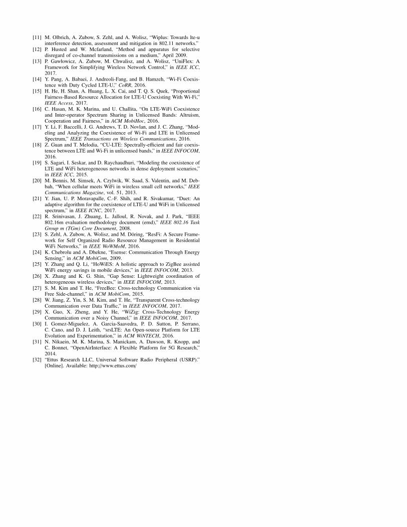
XII. System-level Simulations
We evaluated LtFi system-wide. The objective was to showthat from the LtFi’s air-interface a WiFi node is able toestimate the set of LTE-U BSs in its proximity. Thereforewe consider a typical LTE-U BS deployment, i.e. hexagonalplacement of BSs with frequency-reuse 1 and omni-directionalantennas.
A. Methodology
We conducted system-level simulations using Matlab ac-cording to the methodology recommended by the IEEE802.16m group [22]. The setup mimics an indoor small officescenario. The LTE-U inter-BS distance was set to 50 m. AllLTE-U BSs are using the same unlicensed channel (5.2 GHz)and are transmitting the LtFi signal as described in Sec. VII.For the simulations we used the following simplified modelfor the LtFi receiver according to which the LtFi receiveris able to perfectly decode the information received over theLtFi air-interface as long as the wanted CTC signal was aboveand the interfering CTC signal was below the sensitivity levelof -77 dBm, i.e. 19 dB above the noise floor, respectively.The value was selected as it achieves the best performance3.Finally, the LtFi receiver was placed on a regular grid in thebounding box with side length of 140 m. At each location theLtFi proximity detection algorithm (Listing 2) was executedin order to estimate the number of LTE-U BSs in its vicinity.The remaining parameters are summarized in Table I.
B. Results
Fig. 16a shows for each LtFi receiver location (point inspace) the estimated number of LTE-U BSs. In absence ofShadowing, i.e. σ = 0, we can observe a strong correlationbetween the LtFi’s receiver positions and the number ofestimated LTE-U BSs. For location very close to LTE-UBSs the number of reported BSs is up to seven whereas forlocations between three BSs the reported number is three.
Finally, Fig. 16b shows the results for an environment withShadowing, i.e. σ = 6.
3In case of Atheros WiFi NIC the ED is configured with θ = 23.
-60 -30 0 30 60
location [m]
60
30
0
-30
-60lo
catio
n [m
]
3
4
5
6
7
(a) Without shadowing
-60 -30 0 30 60
location [m]
60
30
0
-30
-60
loca
tion
[m]
0
1
2
3
4
5
6
7
(b) With Shadowing
Fig. 16. Number of detected LTE-U BSs at each spatial location. Blackrectangles mark the location of LTE-U BSs. An ED threshold of θ = 23(-77 dBm) is used.
Takeaways: In a LTE-U network where BSs are operating onthe same unlicensed channel LtFi is able to accurately estimatethe BSs in its proximity.
XIII. RelatedWorkThe present work is based on our previous work where
we proposed an architecture for setting up out-of-band con-trol channel between homogeneous network nodes, namelyresidential WiFi APs [23]. With LtFi we extended this ideatowards cross-technology control between heterogeneous net-work nodes, here LTE-U and WiFi. To the best of ourknowledge, there is no previous work on cross-technologycommunication between LTE-U and WiFi.
So far, the research focus was to enable cross-technologycommunication between WiFi and sensor networks (mostlyZigBee), that coexist in the same 2.4GHz band. Esense [24]and HoWiES [25] enable over-the-air WiFi to ZigBee commu-nication by injecting dummy packets with durations that areunlikely to be used in normal WiFi traffic. They can achieverelatively high throughput, but are burden to already saturatedspectrum. GapSence [26] prepends legacy packets with a cus-tomized preamble containing sequences of energy pulses. Thelength of silent gaps between them encodes the CTC data to be
transmitted. Such approach requires a dedicated hardware andis not compatible with COTS devices. FreeBee [27] modulatesCTC data by shifting the timing of periodic beacon frames,but suffers from low rate being limited by the beacon rate.C-Morse [4], DCTC [28], EMF [5] and WiZig [29] achievehigh CTC rates by utilizing all types of frames. In general,they slightly perturb the transmission timing of WiFi frames toconstruct recognizable radio patterns within negligible delay.Furthermore, they are compliant with existing standards andstrive to be transparent to upper protocol layers. In contrast,in case of LTE-U we cannot modify the transmission timing,as it is tightly scheduled.
XIV. Conclusions
In this paper we introduced LtFi, a system which enablesto set-up a CTC between LTE-U and WiFi. LtFi is fullycompliant and transparent with LTE-U technology and workswith WiFi COTS hardware. LtFi is of low complexity and fullycompliant (transparent) with LTE-U technology. It requires justa simple interface to the LTE-U eNb scheduler to programthe data to be transmitted over the LtFi air interface. OnWiFi side LtFi needs an interface for sampling the MACstate (registers) which is already provided by COTS NICslike Atheros 802.11n/ac. The LtFi X2 interface creates a bi-directional CTC over the Internet which enables to performcross-technology interference and radio resource management.
For future work, we plan to replace our LTE-U hardwareby a more flexible system composed of LTE-U implementedin srsLTE [30] or Eurecom’s OpenAirInterface (OAI) [31]on Software Defined Radios like USRP [32] platform. Thiswill allow us to test concrete cross-technology RRM andinterference management schemes.
XV. Acknowledgment
This work has been supported by the European Union’sHorizon 2020 research and innovation programme under grantagreement No. 645274 (WiSHFUL project).
References[1] “LTE-U Forum.” [Online]. Available: http://www.lteuforum.org[2] “3GPP.” [Online]. Available: http://www.3gpp.org[3] “Cisco Visual Networking Index: Forecast and Methodology,
2016–2021.”[4] Z. Yin, W. Jiang, S. M. Kim, and T. He, “C-Morse: Cross-Technology
Communication with Transparent Morse Coding,” in IEEE INFOCOM,2017.
[5] Z. Chi, Z. Huang, Y. Yao, T. Xie, H. Sun, and T. Zhu, “EMF: EmbeddingMultiple Flows of Information in Existing Traffic for Concurrent Com-munication among Heterogeneous IoT Devices,” in IEEE INFOCOM,2017.
[6] “Real-time LTE/Wi-Fi Coexistence Testbed.” [Online]. Available:http://www.ni.com/white-paper/53044/en/
[7] “LTE-U Technology and Coexistence,” 2015. [Online]. Available:http://www.lteuforum.org/workshop.html
[8] C. Cano and D. J. Leith, “Coexistence of WiFi and LTE in unlicensedbands: A proportional fair allocation scheme,” in IEEE ICC, 2015.
[9] M. Olbrich, A. Zubow, S. Zehl, and A. Wolisz, “Towards lte-u inter-ference detection, assessment and mitigation in 802.11 networks usingcommodity hardware,” arXiv preprint arXiv:1702.04020, 2017.
[10] T. Huhn, “A measurement-based joint power and rate controller for ieee802.11 networks,” Ph.D. dissertation, Technische Universitat Berlin, FGINET Prof. Anja Feldmann, 2013.
[11] M. Olbrich, A. Zubow, S. Zehl, and A. Wolisz, “Wiplus: Towards lte-uinterference detection, assessment and mitigation in 802.11 networks.”
[12] P. Husted and W. Mcfarland, “Method and apparatus for selectivedisregard of co-channel transmissions on a medium,” April 2009.
[13] P. Gawłowicz, A. Zubow, M. Chwalisz, and A. Wolisz, “UniFlex: AFramework for Simplifying Wireless Network Control,” in IEEE ICC,2017.
[14] Y. Pang, A. Babaei, J. Andreoli-Fang, and B. Hamzeh, “Wi-Fi Coexis-tence with Duty Cycled LTE-U,” CoRR, 2016.
[15] H. He, H. Shan, A. Huang, L. X. Cai, and T. Q. S. Quek, “ProportionalFairness-Based Resource Allocation for LTE-U Coexisting With Wi-Fi,”IEEE Access, 2017.
[16] C. Hasan, M. K. Marina, and U. Challita, “On LTE-WiFi Coexistenceand Inter-operator Spectrum Sharing in Unlicensed Bands: Altruism,Cooperation and Fairness,” in ACM MobiHoc, 2016.
[17] Y. Li, F. Baccelli, J. G. Andrews, T. D. Novlan, and J. C. Zhang, “Mod-eling and Analyzing the Coexistence of Wi-Fi and LTE in UnlicensedSpectrum,” IEEE Transactions on Wireless Communications, 2016.
[18] Z. Guan and T. Melodia, “CU-LTE: Spectrally-efficient and fair coexis-tence between LTE and Wi-Fi in unlicensed bands,” in IEEE INFOCOM,2016.
[19] S. Sagari, I. Seskar, and D. Raychaudhuri, “Modeling the coexistence ofLTE and WiFi heterogeneous networks in dense deployment scenarios,”in IEEE ICC, 2015.
[20] M. Bennis, M. Simsek, A. Czylwik, W. Saad, S. Valentin, and M. Deb-bah, “When cellular meets WiFi in wireless small cell networks,” IEEECommunications Magazine, vol. 51, 2013.
[21] Y. Jian, U. P. Moravapalle, C.-F. Shih, and R. Sivakumar, “Duet: Anadaptive algorithm for the coexistence of LTE-U and WiFi in Unlicensedspectrum,” in IEEE ICNC, 2017.
[22] R. Srinivasan, J. Zhuang, L. Jalloul, R. Novak, and J. Park, “IEEE802.16m evaluation methodology document (emd),” IEEE 802.16 TaskGroup m (TGm) Core Document, 2008.
[23] S. Zehl, A. Zubow, A. Wolisz, and M. Doring, “ResFi: A Secure Frame-work for Self Organized Radio Resource Management in ResidentialWiFi Networks,” in IEEE WoWMoM, 2016.
[24] K. Chebrolu and A. Dhekne, “Esense: Communication Through EnergySensing,” in ACM MobiCom, 2009.
[25] Y. Zhang and Q. Li, “HoWiES: A holistic approach to ZigBee assistedWiFi energy savings in mobile devices,” in IEEE INFOCOM, 2013.
[26] X. Zhang and K. G. Shin, “Gap Sense: Lightweight coordination ofheterogeneous wireless devices,” in IEEE INFOCOM, 2013.
[27] S. M. Kim and T. He, “FreeBee: Cross-technology Communication viaFree Side-channel,” in ACM MobiCom, 2015.
[28] W. Jiang, Z. Yin, S. M. Kim, and T. He, “Transparent Cross-technologyCommunication over Data Traffic,” in IEEE INFOCOM, 2017.
[29] X. Guo, X. Zheng, and Y. He, “WiZig: Cross-Technology EnergyCommunication over a Noisy Channel,” in IEEE INFOCOM, 2017.
[30] I. Gomez-Miguelez, A. Garcia-Saavedra, P. D. Sutton, P. Serrano,C. Cano, and D. J. Leith, “srsLTE: An Open-source Platform for LTEEvolution and Experimentation,” in ACM WiNTECH, 2016.
[31] N. Nikaein, M. K. Marina, S. Manickam, A. Dawson, R. Knopp, andC. Bonnet, “OpenAirInterface: A Flexible Platform for 5G Research,”2014.
[32] “Ettus Research LLC, Universal Software Radio Peripheral (USRP).”[Online]. Available: http://www.ettus.com/