Embed Size (px)
Citation preview

LTR: Fluid Drag
Not surprisingly, as a fluid flows past a solid object it exerts a force on the solid. There are severalclasses of force typically discussed in fluid mechanics, but the two most common are drag and lift.
DEFINITION:
The drag force is the component of the force from the fluid on the solid that is in the directionparallel to the flow (here denoted as the x direction).
DEFINITION:
The lift force is the component of the force from the fluid on the solid that is in the directionperpendicular to the flow (here denoted as the y direction).
In both the case of drag and lift the forces arise from two sources: fluid friction (viscousforces), and non-uniform pressure distributions (pressure forces).
NOTE:
Lift forces are only very weakly dependent on friction. they are primarily pressure-derivedforces.
The components of the drag force that arise from friction and pressure are given "specialnames":
DEFINITION:
The skin drag/friction is the portion of the drag force that arises due to shear stresses(viscous effects).
DEFINITION:
The form drag is the portion of the drag force that arises due to normal stresses (pressureeffects).
As the above equations would imply, the components of the drag may be analyticallycalculated if the pressure and shear stress distributions are known (and we will do this later);however, in many cases, these calculations are difficult and experimental measurements ofthese components are useful alternatives.
OUTCOME:
Distinguish between lift, drag, skin friction, and form drag.


LTR: Friction Factors and Drag Coefficients
In performing drag experiments, as with any transport experiments, it is useful to calculate/measuredimensionless quantities (for reasons of generality, scale invariance, etc.).
Taking the frictional force per unit surface area to represent the shear stress, we can make adimensionless group using the fluid density and velocity to get:
DEFINITION:
The coefficient of skin friction or the Fanning friction factor is the ratio of the totalnormalized (i.e., dimensionless) shear stress acting on the surface of a solid.
NOTE:
The Fanning friction factor is the one most often used by chemical engineers
If instead we base our dimensionless group more on the "head losses" (a pressure-related drag tobe discussed next) we get the Darcy friction factor, . While the Darcy factor is more common in
general engineering, it can simply be shown to be 4 times as big as the Fanning friction factor, so becareful which is which!
DEFINITION:
The drag coefficient is a more general dimensionless group that is the ratio of the totalnormalized drag (i.e., not simply skin drag) acting on the surface of a solid. Here, we usethe total projected area rather then the surface area.
NOTE:
Typically in internal flows (pipe flows and friends) we are interested primarily in the skindrag, and use friction factors. In external flows, form drag plays a larger role and we tendto use the (total) drag coefficient.
Correlations and Charts
For laminar flow in a pipe, we can analytically show that the (Fanning) friction factor isgiven by:
In turbulent flows, however, things are more difficult, as the friction factor depends stronglyon the pipe roughness:
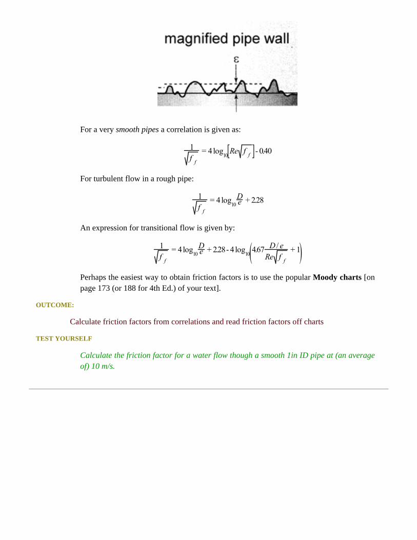
For a very smooth pipes a correlation is given as:
For turbulent flow in a rough pipe:
An expression for transitional flow is given by:
Perhaps the easiest way to obtain friction factors is to use the popular Moody charts [onpage 173 (or 188 for 4th Ed.) of your text].
OUTCOME:
Calculate friction factors from correlations and read friction factors off charts
TEST YOURSELF
Calculate the friction factor for a water flow though a smooth 1in ID pipe at (an averageof) 10 m/s.

LTR: Friction Factors and Drag Coefficients Example
OUTCOME:
Calculate friction factors from correlations and read friction factors off charts
TEST YOURSELF
Calculate the friction factor for a water flow though a smooth 1in ID pipe at (an averageof) 10 m/s.
First we calculate the Reynolds number:
For flow through a circular pipe, this would be considered a turbulent flow. Using theMoody charts, we get .
Alternatively, we can use the correlation for a turbulent flow in a very smooth pipe:
Using "solver" (or similar) and/or trial-and-error, we get using this method.

LTR: Drag in External Flows
In addition to the correlations for internal (pipe) flows discussed previously, there are a number ofexpressions and charts for drag on submersed objects (external flows) in the text.
One of the most famous drag formulas is that of Stoke's drag, used for a viscously dominated flow:
NOTE:
This expression is useful for viscous fluids, but also for small particles (recall the definitionof the Re!). Can you show that the drag coefficient in Stoke's flow is:
As the flow becomes "faster" the character of the wake behind the blunt body changes and thus theform drag increases On Page 141 (or 153 for 4th Ed.) a chart shows the behavior of as a functionof Re.
OUTCOME:
Use friction factors and/or drag coefficients to calculate drag on submersed objects (externalflows) and for internal flows
TEST YOURSELF
Calculate the drag on a Nolan Ryan fastball (100 mph; 7.3 cm diameter).

LTR: Drag in External Flows Example
OUTCOME:
Use friction factors and/or drag coefficients to calculate drag on submersed objects (externalflows) and for internal flows
TEST YOURSELF
Calculate the drag on a Nolan Ryan fastball.
As with just about all drag-related problem, we must first calculate the Reynolds number:
For flow past a sphere, we can get the drag coefficient from the chart on page 153: .
If we now want to calculate the drag force from this we use the definition of the dragcoefficient:
Rearranging to get the drag force, :
which gives us:

LTR: Drag in Pipes
You may have noticed that the normalizing "drag pressure" used thus far has been , whichis often called the dynamic pressure. Another common way to denote "pressure" losses due to drag isto quote them as head losses.
DEFINITION:
The head loss is the energy lost per unit weight of the fluid.
Head losses for straight lengths of pipe are directly related to the friction factor and constitute "majorlosses" in pipe flow:
Head losses for bends and other pipe components are related to an empirical (experimentallymeasured) factor called the loss coefficient/factor, Ki (see page 175 (or 190 in 4th Ed.) for values inpipe bends) and constitute "minor losses" in pipe flow:
Another examples of loss coefficient/factor is for pipe constrictions, where:
or pipe enlargements, where:
NOTE:
The terms "major" and "minor" losses do not necessarily denote which is larger, simplywhich is most common!
In order to use head losses to calculate pressure drops, we use the following equation (which wewill derive later in the course):
OUTCOME:
Estimate friction losses in pipes and pipe networks
TEST YOURSELF
What are the units of a head loss?

LTR: Drag in Pipes Example
OUTCOME:
Estimate friction losses in pipes and pipe networks
TEST YOURSELF
You are analyzing the flow between the hot water heater and the shower in a ranch-stylehome (so that elevation changes may be neglected). Calculate the mainline water pressurewhen the flowrate is 1L/s and the water is flowing through 10 meters of 2cm ID (smooth)pipe, going through 3 90o elbows and you may consider the shower-head equivalent toa wide-open angle valve. (Note: the fluid velocity does not change along the region ofinterest.)
In order to calculate the mainline pressure, we need to figure out the necessary pressure-drop in thesystem described. In order to obtain that, we need to calculate the head losses for each of the partsof the pipe network.
Our calculations, therefore, need to include contributions from:
• Straight pipe ("major") losses• "Minor" losses from the elbows• "Minor" losses from the shower-head
Head losses for the straight length of pipe is obtained from the friction factor, so we must firstcalculate fluid velocity so that we can get the Re:
This gives = 3.18m/s, so that:
Since the flow is strongly turbulent, we will assume that . Also, we get from the charts
to be , so that:
Head losses for both the bends and the shower-head are obtained from the loss factor, using:
Looking up the values of , we get , while , so that the head losses from
these four things (3 elbows and a nozzle) are:

NOTE:
The "minor" losses are bigger than the "major"! Also, we could not group them in this way if wasdifferent for each.
Then, the total head losses are calculated simply by adding these up, whereby we can get the pressuredrop from:
which in our problem becomes:
so that:
This means that the absolute pressure in the line is about 160kPa (since the pressure at the nozzleend must be atmospheric).

LTR: Convective Heat Transfer
As we already discussed, convective heat transfer refers to the transport of heat due to a movingfluid (and in the engineering sense, applies to the case of a fluid "carrying" heat away from a solidboundary). In either sense of the term, it is clear that the rate of heat transfer will depend on the characterof the fluid flow.
The rate expression for convection was suggested by Newton in 1701, commonly called Newton's"Law" of Cooling, and has the form:
EQUATION:
where is the convective heat transfer coefficient. It is sometimes also referred to as a "filmcoefficient" since in some strong flows the temperature changes are confined to a relativelythin film (see below).
"Law" is in quotes above because it is perhaps more correct to think of this expression as an empirical(data fitting) definition of rather than a law. It will depend on:
• the geometry of the solid boundaries (this will typically be known)• the nature of the fluid (conductivity, heat capacity, density, etc. : we can look these up)• the nature of the flow (fluid mechanics!)
NOTE:
Determining the parameter, , will often be the bulk of the work (or at least the only hard part) in agiven convection problem.
OUTCOME:
Perform convective heat transfer calculations
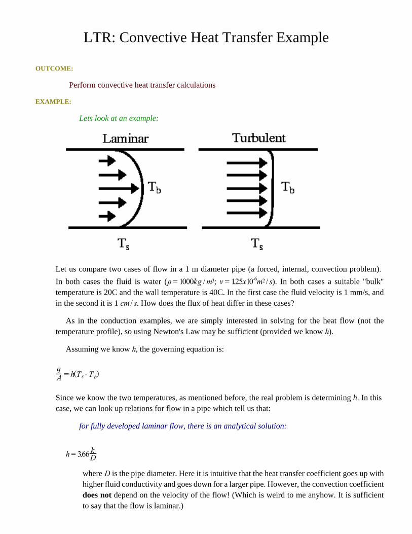
LTR: Convective Heat Transfer Example
OUTCOME:
Perform convective heat transfer calculations
EXAMPLE:
Lets look at an example:
Let us compare two cases of flow in a 1 m diameter pipe (a forced, internal, convection problem).
In both cases the fluid is water ( ; ). In both cases a suitable "bulk"temperature is 20C and the wall temperature is 40C. In the first case the fluid velocity is 1 mm/s, andin the second it is 1 . How does the flux of heat differ in these cases?
As in the conduction examples, we are simply interested in solving for the heat flow (not thetemperature profile), so using Newton's Law may be sufficient (provided we know ).
Assuming we know , the governing equation is:
Since we know the two temperatures, as mentioned before, the real problem is determining h. In thiscase, we can look up relations for flow in a pipe which tell us that:
for fully developed laminar flow, there is an analytical solution:
where is the pipe diameter. Here it is intuitive that the heat transfer coefficient goes up withhigher fluid conductivity and goes down for a larger pipe. However, the convection coefficientdoes not depend on the velocity of the flow! (Which is weird to me anyhow. It is sufficientto say that the flow is laminar.)

for turbulent flow, there is an empirical relation:
where is the fluid velocity. Again the heat transfer coefficient goes up with higher fluidconductivity and goes down (much less!) for a larger pipe, but now it does depend on thevelocity of the flow as well as other properties of the fluid.
So, all we need to do now is determine the nature of the flow in our two cases. One important wayto characterize fluid flows is to calculate the Reynolds number. The Reynolds number is a measure ofthe relative importance of the inertial and viscous forces in a flow.
In a pipe flow (and only in a pipe flow!), the flow is considered laminar for Re<2300 and turbulentfor Re>5000.
Let us calculate Re's for our flows...
(laminar)
(turbulent)
The heat transfer coefficients in each case are:
So,
What would happen if we did this same calculation for air rather than water?
Note:

Often you will not be given any details of the fluid, the flow, (or even the geometry). Instead, you willsimply be told what the "bulk" temperature in the fluid is as well as what the heat transfer coefficient(h) is. This is enough info to solve this type of convection problem.

LTR: Convective Mass Transfer
Convective mass transfer refers to the transport of mass due to a moving fluid. Like heat convection,this typically refers to transport across phases, however, here solid-fluid transport is on equal footingwith liquid-gas transport (rather than being the dominant example of convection). As with heattransport, it is clear that the rate of mass transfer will depend on the character of the fluid flow.
In analogy with Newton's "Law" of Cooling, we can write an expression for the molar flux due toconvection as:
EQUATION:
where is the convective mass transfer coefficient, is the molar flux of species , isthe molar flow of a, and A is the interphase area of contact.
NOTE:
We could write essentially the same expression based on mass concentrations, but will tryto denote mass fluxes/flows with lower case letters. Also, for transport int he gas phase, wewill often use partial pressures instead of molar concentrations.
As with heat transfer may also sometimes be referred to as a "film coefficient".
will depend on:
• the geometry of the phase boundaries (unlike heat transport, if we have gas-liquid transportthis is a very difficult thing to calculate/measure!)
• the nature of the fluid (here the diffusivity)• the nature of the flow (fluid mechanics!)
NOTE:
Again, determining the parameter, , will often be the bulk of the work (or at least the only hard part)in a given convection problem.
OUTCOME:
Perform convective mass transfer calculations
EXAMPLE:
An aspirin sitting in your stomach has a solubility of 0.15 mol/L (so this is the concentration at thesolid-liquid surface). Assuming that the concentration in the bulk of the stomach is zero and that thepill does not shrink, but stays a sphere with a 0.5cm diameter, calculate the molar flow into the stomachwhen the mass transfer coefficient is 0.1 m/s

LTR: Radiative Heat Transfer
As mentioned previously, radiation is unique in that no mass is necessary to bridge the gap betweenthe two bodies which are exchanging heat. Instead, heat is transferred by emittance and absorption ofenergy "rays" or "packets" (photons). This is the way that the sun heats the Earth (clearly, as there isno mass between the two, in space).
The rate expression for radiation emission is associated with the names Stephan (1879) andBoltzmann (1884) who independently proposed the form:
EQUATION:
where is the Stephan-Boltzmann constant, . The above expression is onlyvalid for the simplified case of what we will call a "perfect" radiator, called a "black-body"radiator.
NOTE:
Upon reflection, the choice of the name "black body" should not be surprising, as we haveall experienced the fact that black shirts absorb solar energy more efficiently than whiteshirts. It turns out that they emit the energy more efficiently as well!
EXAMPLE:
Lets look at a very simple example:
Consider the situation where one black body (perfect radiator) is enclosed entirely within theother. We could imagine that body 1, at , is radiating according to:

Clearly all of this energy must hit body 2. Since body number 2, at , is also radiating energy,the energy that is radiated from body 2 and hits body 1 is:
This would lead us to a net heat flow from body 1 is given by:
We have actually oversimplified the real-life situation quite a bit in this example:
• we have used only black bodies• all the energy which body 1 emits reaches body 2
If we instead consider the "realistic" bodies shown here, we can relax these two conditions.
Any Geometry
In order to relax our "aim" condition (that all energy emitted from 1 actually makes it to 2 and viceversa), we clearly need to consider the geometry of the problem (if some of body 1 faces away frombody 2 the energy emitted from that side should not make it to 2 and vice versa).
These geometrical considerations are typically incorporated in a geometrical factor, , called theview factor.
DEFINITION:

The view factor is the fraction of the area of one body that is "seen" by the other body.Alternatively, we might think of it as the fraction of the radiation leaving one body that"hits" the other body.
As you might gather from this definition, is direction specific, meaning that it can only be usedfor heat transfer from body 1 to body 2. The product of and A1 is, however, not direction specific(i.e., A1 = F21A2). This fact is termed reciprocity and simply states that the net heat flow from onebody to the other should not depend on which way it is calculated.
Going back to our first example, we might imagine that some of the radiation leaving body 2 actuallyhits body 2 rather than body 1. This means that F21 is not equal to 1; however, =1 since all radiationleaving body 1 hits body 2, so our expression above is still correct (at least for black bodies in thatgeometrical configuration).
What is F21 in this case?
IMPORTANT:
Two critical properties of the view factor then are:
• F12A1 = F21A2•
Non-Black (Gray) Bodies
Things become considerably more complex if we consider that not all bodies are perfect radiators.A simple method of relaxing the condition of non-black bodies is to introduce a correcting factor forthe amount of energy emitted relative to that of a black body, (emissivity), so that
where is the emissive power of the material (at some temperature, ) and is the emissive powerof a black body (see the equation for the heat flow (the flux times the area) for a black body (above),and remember that power is energy per time....heat flow!). Using this relation, we can write that theheat emitted from body 1 is
Similarly, we can write a correcting factor for the absorption, (absorptivity), so that the heatabsorbed is
It is often assumed that for a "gray" body, one in which and are independent of temperature, andthe emissivity should be equal to the absorptivity ( ). Even this simply rescaling of the radiationflux, however, makes radiation problems considerably more difficult as we now need to consider not
only the initially incident radiation, but also reflected radiation (and we need to include the view factorsfor each rebounded ray!).
For the purposes of this class, we will focus on situations where body 2 is much larger than body 1(so that we can neglect radiation reflecting off of body 2 and we can consider body 2 essentially black)so we can write the new heat flux from body 1 to body 2 as
OUTCOME:
Perform radiative heat transfer calculations
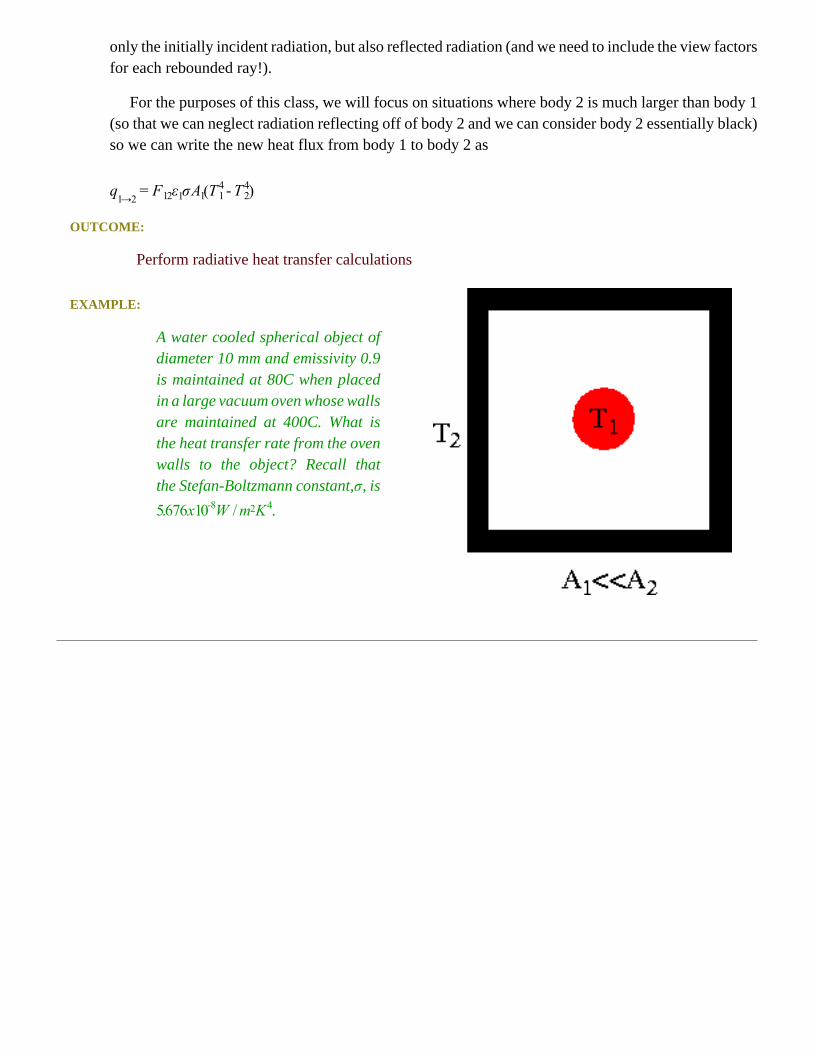
EXAMPLE:
A water cooled spherical object ofdiameter 10 mm and emissivity 0.9is maintained at 80C when placedin a large vacuum oven whose wallsare maintained at 400C. What isthe heat transfer rate from the ovenwalls to the object? Recall thatthe Stefan-Boltzmann constant, , is
.

LTR: Radiative Heat Transfer Example
OUTCOME:
Perform radiative heat transfer calculations
EXAMPLE:
A water cooled spherical object ofdiameter 10 mm and emissivity 0.9is maintained at 80C when placedin a large vacuum oven whose wallsare maintained at 400C. What isthe heat transfer rate from the ovenwalls to the object? Recall thatthe Stefan-Boltzmann constant, , is
.
Since body 2 surrounds body 1 and , the governing equation (heat flow from 1 to 2):
where (since it is the surface area of the sphere).
Plugging in our numbers
so for flow from walls (body 2) to sphere (body 1) .
For simplicity, it is common to try to linearize the relation for radiative heat transfer (if you don'tsee why now, you will in a little bit!). So, if we factor the full equation, we get
If we then assume that (and use the mean, ) the sums can be simplified and the equationcan be re-written

so that if we define as
which leaves us with the final (very simple) form of
If we apply this equation to our previous problem we get for
which is <10% off.
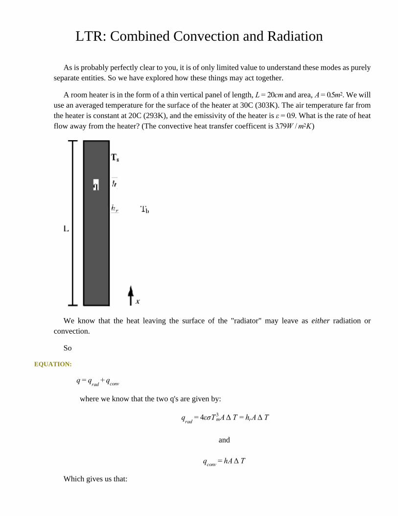
LTR: Combined Convection and Radiation
As is probably perfectly clear to you, it is of only limited value to understand these modes as purelyseparate entities. So we have explored how these things may act together.
A room heater is in the form of a thin vertical panel of length, and area, . We willuse an averaged temperature for the surface of the heater at 30C (303K). The air temperature far fromthe heater is constant at 20C (293K), and the emissivity of the heater is . What is the rate of heatflow away from the heater? (The convective heat transfer coefficent is )
We know that the heat leaving the surface of the "radiator" may leave as either radiation orconvection.
So
EQUATION:
where we know that the two q's are given by:
and
Which gives us that:

GIven that the convective heat transfer coefficent is , we can then calculate our radiativeheat transfer coefficient (with ):