Embed Size (px)
Citation preview

A-1
Luce Bayou Interbasin Transfer Project Description
SUMMARY
The Coastal Water Authority (CWA) is a Conservation and Reclamation District established by the Texas Legislature in 1967 with a Board appointed by the Governor of Texas and the City of Houston. The Luce Bayou Interbasin Transfer Project (LBITP) is a regional water supply project proposed to be implemented by CWA that would transfer raw water from the Trinity River Basin to Lake Houston, a major water supply reservoir for the City of Houston. An overall, general project exhibit providing the identification and location of project facilities is provided as Sheet 1. The LBITP has been an integral part of Texas state water planning for the past 50 years. The project would ultimately convey by underground pipeline and aboveground canal approximately 500 million gallons per day (MGD) of untreated or raw water from the proposed 90-acre Capers Ridge Pump Station on the Trinity River to supplement existing water supplies in Lake Houston in order to provide necessary water service to the surrounding area. The proposed project would include property acquisition within a 300-foot wide corridor planned for the pipeline, and canal. Intake and discharge structures and construction/maintenance areas and easements would also be part of the LBITP. Nine alternatives were reviewed prior to the identification of a preferred alternative (Sheet 2). The LBITP footprint would encompass approximately 1,050 acres in Liberty and Harris Counties, Texas. Approximately 203 acres of waters in the United States, including wetlands, would be impacted by the proposed project. The Sam Houston Electrical Cooperative would supply electric power to the pump station property. Water in the canal would flow by gravity to Lake Houston.
Since 1970, the City of Houston has owned significant water rights in the Trinity River and Lake Livingston. Specific water rights related to this project include the right to divert a maximum rate of 775 cubic feet per second (cfs) from the Trinity River at the LBITP proposed pump station at Capers Ridge. The Capers Ridge Pump Station property was acquired for the LBITP by the City of Houston in 1980 and conveyed to CWA in 2009. The recommended concept for the LBITP includes the proposed pump station installed at the Trinity River, approximately 3 miles of pipeline, a sedimentation basin, approximately 23.5 miles of canal, an equipment maintenance facility, and a discharge structure. The LBITP canal would outfall into the backwaters of Lake Houston on the northeastern shoreline near the confluence with Luce Bayou. Raw water would be treated at the City of Houston owned Northeast Water Purification Plant (NEWPP) and the East Water Purification Plant (EWPP) via the West Canal (Sheet 1). The City of Houston is planning a major expansion of the existing NEWPP that treats water from Lake Houston to provide the Houston metropolitan area with water supplies required by existing water supply contracts.
Treatment of water from Lake Houston occurs at the NEWPP and the EWPP. Lake Houston water supplies are vital to providing water to Harris-Galveston Subsidence District (HGSD) Area Three, which is being progressively converted from groundwater to surface water supply sources in compliance with mandated plans to control area subsidence. Regional water authorities have been created in this area to distribute surface water, but sufficient raw water in Lake Houston and the NEWPP treatment capacity is not currently available to meet projected water supply needs for this portion of the Houston area while allowing for the required conversion from groundwater to surface water sources. The LBITP would provide necessary water supplies to meet contracted demands identified by the City of Houston.

A-2
2.0 NEED FOR AND PURPOSE OF PROJECT
The LBITP is the interbasin transfer of raw water from the Trinity River to Lake Houston as stipulated by conditions established by an existing water rights permit issued by the Texas Commission on Environmental Quality (TCEQ). The City of Houston currently operates three surface water treatment plans: the NEWPP, the EWPP, and the Southeast Water Purification Plant (SEWPP). Water in Lake Houston is and will continue to be treated at both the NEWPP and the EWPP and distributed to water end users. Trinity River water conveyed by the LBITP to Lake Houston would need to begin no later than 2020. The City of Houston would need to treat water at both the NEWPP and EWPP to meet demands by City of Houston water customers. The LBITP is a long-planned water supply project that is critical to meeting projected growth and increased water demands vital to sustaining the long-term economic health of the Houston metropolitan area and surrounding communities. The permitting and preliminary engineering phases are being financed by a $28 million Texas Water Development Board (TWDB) Water Infrastructure Fund (WIF) loan.
The need for the LBITP is to meet the projected water demand and to increase available water supplies to comply with contracted, future demands identified by the City of Houston. A secondary objective of the LBITP is to assist with the conversion of groundwater to surface water supply sources to control land subsidence that has occurred from excessive pumping of area groundwater aquifers. The LBITP is a cornerstone in satisfying the mandated groundwater-to-surface water conversion program designed to control subsidence in the Houston area. The conversion to surface water supplies is expected to slow subsidence by 2010. By 2020, subsidence is expected to be controlled and finally halted by 2030. Water levels within the Gulf Coast Aquifer are predicted to rebound by as much as 125 feet through the implementation of the HGSD’s groundwater withdrawal reduction plan.
The primary purpose of the LBITP is to meet the anticipated water demands based on population projections and to increase treated water supplies to comply with contracted, future demands identified by the City of Houston. The LBITP is a long-planned water supply project identified by regional water planning efforts performed by the Texas Water Development Board (TWDB). The LBITP has been included as a recommended water management strategy for the last 50 years and, more recently, in the 2006 Region H Water Plan, the initially adopted 2011 Region H Water Plan, the 2007 State Water Plan, and the draft 2012 State Water Plan. A secondary objective is to meet the HGSD’s mandated groundwater reduction plan to limit groundwater use by Houston area municipalities by as much as 20 percent of total demand by 2030. The HGSD was established by the State of Texas in 1975 to regulate groundwater pumping in Harris and Galveston Counties. Significant land subsidence has occurred from excessive pumping of area groundwater aquifers. The HGSD and the Fort Bend County Subsidence District have developed regulatory plans that mandate the reduction of groundwater pumping starting in 2010 or 2013, respectively, and continuing through 2030.
Due to uncertainty in future growth and water demand, the LBITP would be designed to accommodate a peak pumping and conveyance capacity of 500 MGD, or 775 cfs; these capacities are also based on the conveyance limits established by the existing water rights permit issued by the TCEQ. To meet forecasted contracted water demand allocations with existing supplies, the LBITP would supply 230 MGD in 2020 and 425 MGD in 2040 to Lake Houston for treatment and conveyance to end users in accordance with contract conditions.
SITE ANALYSIS AND SITE DESCRIPTION
The proposed project begins in central Liberty County along Capers Ridge at the Trinity River and terminates in northeast Harris County near the confluence of Luce Bayou and Lake Houston. The LBITP includes a proposed approximately 90-acre Trinity River pump station

A-3
at Capers Ridge, approximately 3 miles of pipeline, a 20-acre sedimentation basin, approximately 23.5 miles of canal, and a discharge structure that would outfall into the backwaters of Lake Houston. The proposed project is comprised of forested areas, agricultural land, grazing land, and public rights-of-way (ROWs). Waters of the United States are interspersed throughout the entire project corridor. Sheets 4 through 32 present a project layout with delineated wetland boundaries.
3.1 Project Components
The project begins at the Trinity River along Capers Ridge with the construction of the proposed pump station. The CWA-owned pump station tract encompasses approximately 90-acres (Sheet 4). The individual elements of the pump station are listed in Section 4.3. Water would be removed from the Trinity River via the pump station intake structure and flow into a pipeline located within a 300-foot ROW corridor for approximately 3 miles (Sheets 9 – 11). The pipeline would be constructed 6-foot below natural ground and would consist of two, 108-inch pipes constructed 20 feet apart (Sheet 35). The pipeline would discharge into a proposed 20-acre sedimentation basin and the water conveyance structure would transition into the proposed canal (Sheet 12). The canal would be constructed within a 300-foot ROW (Sheet 36). The proposed earthen canal would have a 20-foot wide bottom section with 4:1 side slopes and would be generally 7 feet deep. The top of banks would be approximately 100 feet apart. An access road would be constructed on each side of the proposed canal (Sheet 36). The proposed canal is approximately 23.5 miles in length, terminating at the discharge structure at the backwaters of Lake Houston along the northeastern confluence with Luce Bayou. Approximately 700 feet east of the discharge location at Luce Bayou, the canal transitions to a box culvert prior to discharge (Sheets 32 – 34). The culvert would be constructed of three 6-foot x 8-foot concrete box culverts and would discharge below the ordinary high water mark (OHWM) of Luce Bayou. A concrete headwall would be constructed at the point where the culvert structure discharges into Luce Bayou.
Water control gates would be constructed to help control water levels in the canal (Sheet 37). The gates that would be situated within the canal would raise and lower to allow a greater or smaller volume of water through the canal depending upon conditions outlined by the client. In general, the water level control gate structures would be placed along the canal at locations where a hydraulic drop is necessary to lower the water elevation in the canal. These gate structures would serve to regulate the surface water level by increasing or decreasing the allowable flow through the canal. The gates would operate using hydraulic pressure.
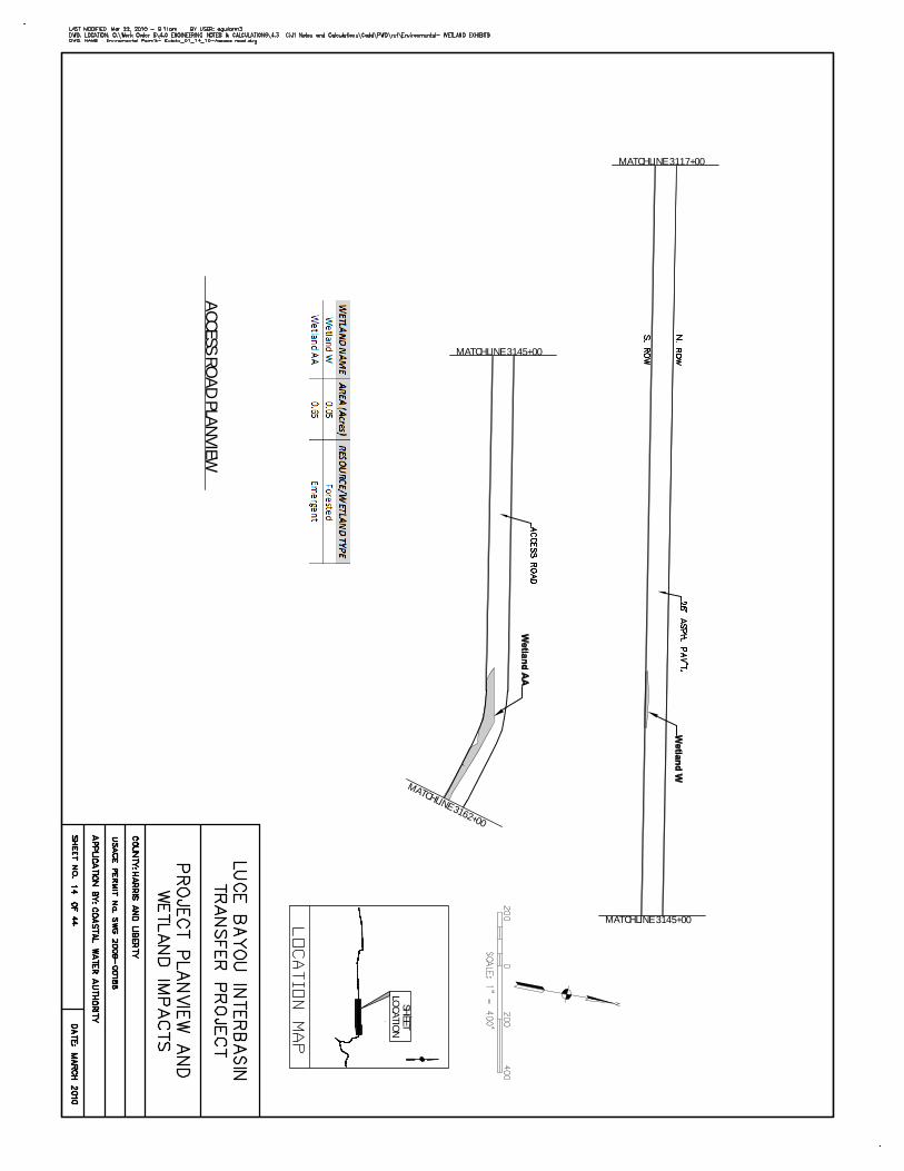
The proposed access road to the Capers Ridge Pump Station would be constructed beginning at FM 1008. The asphalt access road would have an 80-foot ROW (Sheets 13 – 15). The road would follow the existing Timberline Road within the existing roadway footprint until reaching the entrance to the Harrison Tract. On the Harrison Tract, the access road would generally follow the existing ranch road traversing along Capers Ridge and providing access to the sedimentation basin and the proposed pump station property. The proposed access road traversing the Harrison Tract is approximately 2.5 miles long encompassing 25 acres before it enters the proposed LBITP ROW. After entering the LBITP ROW, the access road would be contained in the project ROW until the ROW terminates at the proposed pump station. Approximately 2.4 miles of access road would be constructed within the LBITP ROW
3.1.1 Wetland Systems
An investigation for waters of the United States and wetlands was performed on the proposed LBITP corridor and pump station site. The preliminary jurisdictional determination process

A-4
has been implemented for the LBITP. During the investigation, identified wetlands and natural drainage features were considered jurisdictional. Man-made upland drainage ditches and ponds excavated from uplands were identified as non-jurisdictional. The investigation resulted in the identification and delineation of approximately 203.10 acres of jurisdictional aquatic resources (Sheets 4 – 33 and Sheet 39). Of this total, approximately 200.95 acres consist of wetlands resources. Approximately 118.93 acres of forested wetlands occur within the project footprint. Approximately 45.26 acres of emergent wetlands, approximately 11.21 acres of an open water wetland, and approximately 25.55 acres of scrub-shrub wetlands occur within the project footprint. All wetlands within the LBITP corridor would be adversely impacted by construction and grading activities. Clearing of the corridor would require the use of mechanized land clearing equipment, which is a considered a regulated fill activity.
Waterbodies
Approximately 2.15 acres of waters of the United States were identified during field investigations. Of these 2.15 acres, approximately 0.18 acre is comprised of small, natural drainages that exhibit an OHWM. The remaining 1.97 acres are comprised of the confluence of Lake Houston and Luce Bayou (0.30 acre) and the Trinity River (1.67 acres) [Sheets 4 and 32].
3.1.3 Drainages
The approximate 0.18 acre of small, natural drainages would be excavated within the LBITP corridor footprint. Flows from the portions of these drainages located outside the project footprint would be directed into a small drainage ditch within the corridor. The canal would flow into underground siphons. Small drainage swales would then cross the canal and flow into drainage ditches. Flows would be directed back to ditches within the corridor and returned to the drainages to continue in the original flow path. The siphon areas would also serve as potential wildlife crossings.
3.1.4 Trinity River
The Capers Ridge Pump Station would be constructed at the Trinity River. The construction of the pump station would include impacts below the OHWM of the Trinity River. Approximately up to 1.67 acres of the Trinity River would be impacted during construction. Impacts would include placement of a trash rack, construction of a headwall, construction of concrete slope protection at the base of the headwall, placement of a sluice gate in the headwall, construction of an intake structure, and placement of riprap for erosion protection. Excavation would also occur below the OHWM; the excavation is needed to construct the pump station and associated erosion protection (Sheets 5 – 8).
Approximately 330 cubic yards of concrete slope protection (including headwall and concrete toe) and an additional approximate 470 cubic yards of backfill material would be placed below the OHWM at the proposed pump station. This would allow for construction of the sluice gate, trash track, and headwall wall for the pump station. Approximately 1,100 cubic yards of material would be excavated below the OHWM to allow for construction of the pump station and placement of the concrete slope protection and headwall. In addition, riprap would be placed along the banks of the Trinity River upstream and downstream of the intake structure for erosion protection. Approximately, 7,600 cubic yards of riprap would be placed below the OHWM of the Trinity River. To allow for placement of the riprap, approximately 6,000 cubic yards of material would be excavated below the OHWM of the Trinity River.
3.1.5 Lake Houston Near Luce Bayou
The proposed canal would discharge into the backwaters of Lake Houston along the northeast shoreline downstream of the confluence with Luce Bayou. The canal would

A-5
discharge below the OHWM through three box culverts. The dimensions of each of the three culverts are 6-foot by 8-foot (Sheets 32 – 34). The culverts would terminate at a concrete headwall. Through erosion analysis it was determined that erosion protection is needed at the discharge point. Approximately 975 cubic yards of riprap would be placed below the OHWM. Construction of the concrete headwall and placement of erosion protection would impact approximately 0.30 acre below the OHWM.
3.1.6 Temporary Construction Impacts at the Trinity River and Lake Houston
Portions of both the Trinity River and the backwater area of Lake Houston near the confluence of Luce Bayou would be dewatered to allow for construction and equipment access. Certain portions of the proposed for the LBITP, namely the river bank stabilization, pump station intake, and canal outfall must be constructed within river boundaries. Other structures, such as the pump bay, will be constructed further inland, but will still be in areas that are heavily influenced by groundwater and river water. Contractors will have to implement construction strategies to control and redirect water around the construction area, and maintain a dry, safe working area. The means and methods of construction are traditionally left up to the contractor and not dictated by the engineer, unless special circumstances necessitate direction. For this reason, a specific definition of the in-river construction methods cannot be provided; however, a general description of means and methods that have been successfully implemented on countless similar projects can be discussed.
Contractors will construct a coffer dam using steel sheet piling to secure the area in which the excavation will be made. Earthen coffer dams are sometimes constructed in lieu of sheet pile coffer dams; however, an earthen coffer dam is not anticipated to be used for this application due to the narrow, quick-moving river conditions. A sheet pile coffer dam consists of a series of panels with interlocking connections, driven into the ground with impact or vibratory hammers to form an impermeable barrier. Sheet piling is typically driven to a depth that is twice as deep as its exposed face. For example, it will have 33 percent of the total length above ground and 67 percent of the total length below ground. Contractors will place sheet piling on three sides of the excavation leaving the inland face open (free of sheet piling) or partially open. Sheet piling will be placed five to ten feet beyond the boundary of the proposed structures to leave working space and room for concrete forms. The height of the sheet piling will be determined by the contractor based on the water surface elevation of periodic storm events within the river. Once the sheet piling is put in place, the contractor will begin to dewater and excavate within the coffer dam.
Piezometric dewatering wells will be constructed prior to or immediately after constructing the coffer dam and will continue to be used throughout construction in order control the influx of groundwater. Sump pumps will also be used throughout the entire construction process within the coffer dam. The depth of the excavation will be approximately five feet below the bottom of the proposed structure. Once the sheet piling is in place and the excavation is complete, the contractor will construct the structure within the dry, secure workspace similarly to how the structure would be constructed above ground, using forms, concrete, and rebar. Barges may be occasionally used by the contractor to provide a floating surface within the river on which to place cranes and pile driving equipment. All of the sheet piling will be removed by the contractor once the structure and bank stabilization is complete and ready to be submerged.
Land Use Compatibility

A-6
The LBITP corridor traverses timberland, agricultural land, and rural residential land in Liberty and Harris Counties. The canal would primarily be constructed in forested areas and agricultural land. The forested areas are generally in remote areas with limited human access. The agricultural land exhibits an extensive canal and drainage network for irrigating and draining agricultural fields. The proposed LBITP canal would be a feature on the landscape somewhat similar to the existing agricultural ditches and canals that currently exist within or immediately adjacent to the proposed LBITP. The Dayton Canal is approximately 12 miles to the south of the proposed LBITP canal and similar in nature and extent.
Site Acreage
The proposed LBITP footprint would encompass approximately 1,050 acres and include the canal/pipeline corridor, pump station tract, sedimentation basin, access road, and maintenance area. The LBITP acreage is the minimum amount needed to construct and operate the proposed project.
Transportation Access
Numerous roadways intersect the proposed LBITP; major roadway crossings include SH 321, FM 2100, and FM 1008. The proposed project would not eliminate or change access to any public roadways. Chain-link fencing would be constructed at the major road crossings as security to prevent public access. Safety barriers would be constructed to aid in the prevention of automobiles entering the canal during traffic accidents. During construction and maintenance of the proposed canal, access to construction areas would be via existing roadways or CWA-owned property. The proposed canal would have a maintenance road on each side of the canal. One maintenance/access road would be constructed outside the footprint of the proposed canal corridor; it would be constructed on the proposed mitigation tract. This road would follow an existing unimproved ranch road that would be widened and improved. The maintenance road would provide access to the Capers Ridge Pump Station and the sedimentation basin. The LBITP would not interrupt area utilities.

0 3Miles
O:\W
ork O
rder 6
\3.0 R
EFER
ENCE
SUP
PORT
DOC
UMEN
TS\3.
4 NE
PA D
ocum
ents\
3.4.29
IP\ex
hibits
\Exh
ibit_1
_Vici
nityM
ap.m
xd
Basemap Source: ESRI 2008 StreetMap data.
LegendProposed ROWHarrison TractCapers Ridge Pump Station Tract
LBITP Corridor
1008
2100
1409
1960
163
CR 2285
CR 2317
686
Gillen BayouGil len Bayou
LakeHouston
Capers Ridge Pump Station
Huffman
SedimentationBasin
ReidlandReservoir
MitigationTract
StoesserReservoir
LibertyCounty
HarrisCounty
MontgomeryCounty
LL uu cc ee BB aa yy oo uu
Old RiverOld River
CC ee dd aa rr BB aa yy oo uu
GG aa yy ll oo rr CC rr ee ee kk
EE aa ss tt FF oo rr kk SS aa nn JJ aa cc ii nn tt oo RR
ii vv ee rr
BB ii gg BB aa yy oo uu
LLoonngg BBrraann cc hh
OO rr aa nn gg ee BB rr aa nn cc hhOO
l ldd RRi iv veer r DDr raai in n
CCooww BB rr aa nn cc hh
MM aa rr ss hh BB rr aann cc hh
FF rreenn cchh CCr re ee ekk
RR oo cc kk yy BB rr aa nn cc hh
DDaavviiss BBaayyoouu
CCa ammpp BBrraann cchh BBiigg BBaa yy oo uu
Long John CreekLong John CreekLong John Creek
Long John Creek
Davis BayouDavis Bayou
Self B
ayou
Self B
ayou
Self B
ayou
Self B
ayou
Davis Bayou
Davis Bayou
Davis BayouDavis Bayou
Atascocita
Liberty
Dayton
Plum Grove
Kenefick
Dayton Lakes
Patton VillageRoman Forest
Splendora
Project Location
Harris
Liberty
Montgomery
Houston90
59
Liberty
Hardin
Harris
San Jacinto Polk
Chambers
Montgomery
Big Thicket National PreserveBig Thicket National Preserve
Luce BayouInterbasin Transfer Project
Vicinity Map
Application By: Coastal Water Authority
Counties: Liberty & Harris State: Texas
Sheet 1 of 44 Date: March 2010
USACE Permit No. : SWG 2009-00188

Galveston Bay
LakeLivingston
LakeHouston
Sam HoustonSam HoustonNational ForestNational Forest
Existing Trinity RiverPump Station
FM 1485
FM 2 1 00
FM 1008
FM 1960
2 3
2,32,3,4
4A,5A
6A
5
4
6
1
1Capers RidgePump Station
Northeast WaterTreatment Plant
East Fork San Jacinto River
Tr inity River
George Bush Intercontinental Airport
Houston
Big ThicketBig Thicket National Preserve National Preserve
Lake HoustonLake HoustonState ParkState Park
Houston
LibertyLibertyDaytonDayton
ConroeConroe
Patton VillagePatton Village
ClevelandCleveland
LivingstonLivingston
GrangerlandGrangerland
Old RiverOld River-Winfree-Winfree
The Woodlands
LIBERTY
HARRIS
POLK
SAN JACINTO
MONTGOMERY
WALKER
HARDIN
CHAMBERS
45
59
190
90
59
59
787
146
321
105
150
156
8
494
306
548
336
249
227
512
57
393
261
242
573
105
150
105
336
105
146
0 35,000Feet
O:\W
ork O
rder 6
\3.0 R
EFER
ENCE
SUPP
ORT D
OCUM
ENTS
\3.4
NEPA
Doc
umen
ts\3.4
.29 IP
\exhib
its\A
lterna
rives
.mxd
LegendCounty BoundaryPipelineCanal
Existing Natural ChannelFacilities
Source - ESRI (2002) Alternative Alignments
Application By: Coastal Water Authority
Counties: Liberty & Harris State: Texas
Sheet 2 of 44 Date: March 2010
Luce BayouInterbasin Transfer Project
USACE Permit No. : SWG 2009-00188

0 3
Miles
O:\W
ork
Ord
er
6\7
.0 P
UB
LIS
HE
D D
OC
UM
EN
TS
\7.1
Re
port
s\E
nviro
nm
ent
al A
sses
sme
nt\E
xhib
its\S
ect
ion
_3_
Ma
ps\E
xhib
it_3-
44_
We
tlan
d_Im
pac
t_P
age
_La
yout
.mxd
ÜBasemap Source: ESRI 2008 StreetMap data.
Legend
Proposed Alignment
Harrison Tract
Capers Ridge Pump Station
LBITP Corridor
Az
A¥
1008
2100
1409
1960
163
CR
2285
CR 2317
Aþ
686
Gillen BayouGillen Bayou
It
LakeHouston
Capers Ridge Pump Station
Huffman
SedimentationBasin
ReidlandReservoir
MitigationTract
StoesserReservoir
Luce
Bay
ou
Ceda
r Bay
ou
Tann
er B
ayou
LibertyCounty
HarrisCounty
MontgomeryCounty
LL uu cc eeBB
aayy
oouu
Old R
iverO
ld River
CC ee dd aa rr BB aa yy oo uu
GGaa yy ll oo rr CC rr ee ee kk
EE aa ss tt FF oo rr kkSS
aa nnJJ aa cc ii nn
tt ooRR
ii vvee rr
BB ii gg BB aa yy oo uu
LLoonngg BBrraann cc hh
OOrr aa nn gg ee
BB rr aa nn cc hhOO
l lddRR
i iv veer rDDr raai in n
CCooww
BB rr aann cc hh
MMaa rr ss hh
BBrr aa
nn cc hh
FFrreenn cc hh CCr re ee e
kk
RR oo cc kk yy BB rr aa nn cc hh
DDaavviiss BBaayyoouu
CCa amm
pp BBrraann cchh BBiigg BBaa yy oo uu
Long John CreekLong John CreekLong John Creek
Long John Creek
Davis B
ayouD
avis Bayou
Self
Bay
ouSe
lf B
ayou
Davis Bayou
Davis Bayou
Davis BayouDavis Bayou
Atascocita
Liberty
Dayton
Plum Grove
Kenefick
Dayton Lakes
Patton Village
Roman Forest
Splendora
24
29
23
2122
30
27
31
10
25
32
15
19
26
14
20
17
11
28
18
413
12
16
9
Aþ
Az
C|
A¥
C|
Project Location
Harri s
Liberty
Montgomery
Houston
£¤90
Liberty
Hardin
Harris Chambers
San Jacinto
Montgomery
Luce BayouInterbasin Transfer Project
Wetland Impacts Page Layout
Application By: Coastal Water Authority
Counties: Liberty & Harris State: Texas
Sheet 3 of 44 Date: March 2010
USACE Permit No. : SWG 2009-00188

TRINITY RIVER
LOCA
TION
MAP
LOCA
TION
MAP
SHEET
LOCATIO
N
PUM
P STATION
SEE DETA
ILO
N SH
EET 6 OF 44
PUM
P STATION
RIP RAP SEE D
ETAILO
N SH
EET 7 AND
8 OF 44
CAPERS RID
GE PU
MP
STATIO
N TRACT
PIPELINE CONTINUES

O:\W
ork O
rder 6
\3.0 R
EFER
ENCE
SUP
PORT
DOC
UMEN
TS\3.
4 NE
PA D
ocum
ents\
3.4.29
IP\ex
hibits
\She
et_5_
of_44
_Pum
pSta.
mxd
Caper's Ridge Pump StationSite Plan
Luce BayouInterbasin Transfer Project
Application By: Coastal Water Authority
Counties: Liberty & Harris State: Texas
Sheet 5 of 44 Date: March 2010
USAGE Permit No. : SWG 2009-00188
Fill Volume = 800 Cubic yards of concreteExcavation Volume = 1,100 Cubic yardsFill Area = 0.10 AcreExcavation Area = 0.10 Acre

O:\W
ork O
rder 6
\3.0 R
EFER
ENCE
SUP
PORT
DOC
UMEN
TS\3.
4 NE
PA D
ocum
ents\
3.4.29
IP\ex
hibits
\She
et_6_
of_44
_Cros
sSec
tion.m
xd
Caper's Ridge Pump StationCross Section
Luce BayouInterbasin Transfer Project
Application By: Coastal Water Authority
Counties: Liberty & Harris State: Texas
Sheet 6 of 44 Date: March 2010
USAGE Permit No. : SWG 2009-00188
Fill Volume = 800 Cubic yards of concreteExcavation Volume = 1,100 Cubic yardsFill Area = 0.10 AcreExcavation Area = 0.10 Acre

SHEET 1
O:\W
ork O
rder 6
\3.0 R
EFER
ENCE
SUP
PORT
DOC
UMEN
TS\3.
4 NE
PA D
ocum
ents\
3.4.29
IP\ex
hibits
\Alte
rnativ
e_1_
Plan_
View.
mxd
Project Location
Harris
Liberty
Montgomery
Houston90
59
Liberty
Hardin
Harris
San Jacinto Polk
Chambers
Montgomery
Big Thicket National PreserveBig Thicket National Preserve
Capers Ridge Pump StationSlope Protection Alternative
Application By: Coastal Water AuthorityCounties: Liberty & Harris State: Texas
Sheet 7 of 44 Date: March 2010
Luce BayouInterbasin Transfer Project
Plan View
Fill Volume = 7,600 Cubic yards of riprapExcavation Volume = 6,000 Cubic yardsFill Area = 1.57 AcresExcavation Area = 1.57 Acres

O:\W
ork O
rder 6
\3.0 R
EFER
ENCE
SUP
PORT
DOC
UMEN
TS\3.
4 NE
PA D
ocum
ents\
3.4.29
IP\ex
hibits
\Alte
rnati
ve_1
_Pro
file.m
xd
Capers Ridge Pump StationSlope Protection Alternative
Luce BayouInterbasin Transfer Project
Profile
Application By: Coastal Water Authority
Counties: Liberty & Harris State: Texas
Sheet 8 of 44 Date: March 2010
USAGE Permit No. : SWG 2009-00188
Fill Volume = 7,600 Cubic yards of riprapExcavation Volume = 6,000 Cubic yardsFill Area = 1.57 AcresExcavation Area = 1.57 Acres

CAPERS RIDGE PUMP STATION
TRACT CONTINUES
TRINITY RIVER
LOCA
TION
MAP
LOCA
TION
MAP
SHEET
LOCATIO
N
MATCHLINE 2119+00
PIPELINE PLA
NVIEW

TRINITY RIVER
LOCA
TION
MAP
LOCA
TION
MAP
SHEET
LOCATIO
N
MATCHLINE 2048+00
MATCHLINE 2087+00
MATCHLINE 2087+00
MATCHLINE 2119+00
PIPELINE PLA
NVIEW

SEDIMENTATION
BASIN CONTINUES
TRINITY RIVER
LOCA
TION
MAP
LOCA
TION
MAP
SHEET
LOCATIO
N
MATCHLINE 2048+00
PIPELINE PLA
NVIEW
ACCESS RO
AD
CON
TINU
ES

TRINITY RIVER
LOCA
TION
MAP
LOCA
TION
MAP
SHEET
LOCATIO
N
MATCHLINE 1208+00
MATCHLINE 1234+00
MATCHLINE 1234+00
CAN
AL A
ND
SEDIM
ENTA
TION
BASIN
PLAN
VIEW
SEDIM
ENTA
TION
BASIN
PIPELINE CONTINUES
SIPHO
N

MATCHLINE 3162+00
PIPELINE
SHEET
LOCATIO
N
ACCESS RO
AD
PLAN
VIEW
MATCHLINE 3117+00
MATCHLINE 3145+00
MATCHLINE 3145+00
MATCHLINE 3162+00
SHEET
LOCATIO
N
ACCESS RO
AD
PLAN
VIEW

MATCHLINE 3090+00
MATCHLINE 3117+00
MATCHLINE 3090+00
SHEET
LOCATIO
N
HARRISO
N TRACT
FRON
T GATE
ACCESS RO
AD
PLAN
VIEW

MATCHLINE 1181+00
MATCHLINE 1160+00
MATCHLINE 1208+00
MATCHLINE 1181+00
TRINITY RIVER
LOCA
TION
MAP
LOCA
TION
MAP
SHEET
LOCATIO
N
CAN
AL PLA
NVIEW
SIPHO
N
SIPHO
N
ACCESS BRID
GE
SEE SHEET 12 O
F 44FO
R D
ETAILS

MATCHLINE 1160+00
MATCHLINE 1133+00
MATCHLINE 1110+00
MATCHLINE 1133+00
SHEET
LOCATIO
N
HWY 321
FM 1008
LOCA
TION
MAP
CAN
AL PLA
NVIEW
SIPHO
N
SIPHO
N
SIPHO
N

MATCHLIN
E 1110+00
MATCHLIN
E 1084+00
SHEET
LOCATIO
N
HWY 321
FM 1008
LOCA
TION
MAP
WA
TER LEVELCO
NTRO
L GA
TES
CAN
AL PLA
NVIEW

WA
TER LEVELCO
NTRO
L GA
TES
MATCHLINE 1084+00
MATCHLIN
E 1055+00
MATCHLIN
E 1026+00
MATCHLIN
E 1055+00
SHEET
LOCATIO
N
HWY 321
FM 1008
LOCA
TION
MAP
FM 1080
CAN
AL PLA
NVIEW
SIPHO
N
SIPHO
N

MATCHLIN
E 1026+00
MATCHLINE 982+00
MATCHLIN
E 1007+00
SHEET
LOCATIO
N
HWY 321
FM 1008
LOCA
TION
MAP
MATCHLIN
E 1007+00
CAN
AL PLA
NVIEW
SIPHO
N

SHEET
LOCATIO
N
SH 321
MATCHLINE 871+00
MATCHLINE 910+00
MATCHLINE 910+00
MATCHLINE 950+00
MATCHLINE 950+00
MATCHLINE 982+00
HWY 321
FM 1008
LOCA
TION
MAP
WATER CO
NTRO
LG
ATES
CAN
AL PLA
NVIEW
SIPHO
N

SHEET
LOCATIO
N
MATCH
LINE 776+00
MATCH
LINE 803+00
MATCH
LINE 803+00
MATCHLINE 840+00
MATCHLINE 840+00
MATCHLINE 871+00
HWY 321
REID
LAND
RESERV.
LOCA
TION
MAP
CAN
AL PLA
NVIEW
SIPHO
N

MATCH
LINE 755+00
MATCHLINE 690+00
MATCHLINE 729+00
MATCHLINE 729+00
MATCH
LINE 776+00
MATCH
LINE 755+00
SHEET
LOCATIO
N
LOCA
TION
MAP
REID
LAND
RESERV.
WA
TER LEVELCO
NTRO
L GA
TES
CAN
AL PLA
NVIEW

MATCHLINE 576+00
MATCHLINE 614+00
MATCHLINE 614+00
MATCHLINE 652+00
MATCHLINE 652+00
MATCHLINE 690+00
SHEET
LOCATIO
N
LOCA
TION
MAP
REID
LAND
RESERV.
CAN
AL PLA
NVIEW

SHEET
LOCATIO
N
LOCA
TION
MAP
REID
LAND
RESERV.
MATCH
LINE 530+00
MATCHLINE 576+00
MATCH
LINE 530+00
MATCH
LINE 503+00
WATER CO
NTRO
LG
ATES
CAN
AL PLA
NVIEW
SIPHO
N

SHEET
LOCATIO
N
LOCA
TION
MAP
REID
LAND
RESERV.
MATCHLINE 466+00
MATCH
LINE 430+00
MATCH
LINE 503+00
MATCHLINE 466+00
CAN
AL PLA
NVIEW
SIPHO
N

SHEET
LOCATIO
N
LOCA
TION
MAP
REID
LAND
RESERV.
MATCH
LINE 367+00
MATCH
LINE 393+00
MATCH
LINE 393+00
MATCH
LINE 417+00
MATCH
LINE 417+00
MATCH
LINE 430+00
CAN
AL PLA
NVIEW
SIPHO
N

SHEET
LOCATIO
N
MATCH
LINE 322+00
LOCA
TION
MAP
REID
LAND
RESERV.
MATCH
LINE 367+00
CAN
AL PLA
NVIEW
ACCESS BRID
GE

MATCH
LINE 266+00
MATCH
LINE 238+00
MATCH
LINE 294+00
MATCH
LINE 266+00
SHEET
LOCATIO
N
FM2100
SCOTT ROAD
LAKE
HO
USTO
N
LOCA
TION
MAP
MATCH
LINE 322+00
MATCH
LINE 294+00
CAN
AL PLA
NVIEW
WATER CO
NTRO
LG
ATES
SIPHO
N
SIPHO
N

MATCHLINE 197+50
MATCH
LINE 218+00
MATCHLINE 197+50
MATCH
LINE 158+00
MATCH
LINE 238+00
MATCH
LINE 218+00
SHEET
LOCATIO
N
FM2100
SCOTT ROAD
LAKE
HO
USTO
N
LOCA
TION
MAP
CR 624
CAN
AL PLA
NVIEW
SIPHO
N
SIPHO
N

MATCHLINE 120+00
MATCH
LINE 80+00
WATER CO
NTRO
LG
ATES
MATCHLINE 120+00
MATCH
LINE 158+00
SHEET
LOCATIO
N
FM2100
SCOTT ROAD
LAKE
HO
USTO
N
LOCA
TION
MAP
CAN
AL PLA
NVIEW
SIPHO
NSIPH
ON
SIPHO
N

SHEET
LOCATIO
N
MATCHLINE 45+00
MATCHLINE 45+00
MATCH
LINE 80+00
OU
TFALL STRU
CTURE
SEE DETA
IL ON
SHEET 33 O
F 44
LUCE BAYO
U
FM2100
SCOTT ROAD
LAKE
HO
USTO
N
LOCA
TION
MAP
FM 2100
CAN
AL PLA
NVIEW
SIPHO
N


PLA
N V
IEW
PR
OFILE
VIEW
SA
FETY
RAC
K
NA
TUR
AL G
RO
UN
D
SAFETY RACK
CA
NA
L SLOPE
3 8'x7' CO
NC
RETE BO
XES
16' MIN
IMU
M BER
M
CE
NTE
RLIN
E O
F SIPHO
N
SIPH
ON
CR
OSS
SEC
TION
7'
8'2'
6"
OP
EN
EA
RTH
EN
CAN
AL
OP
EN
CA
NA
L EARTH
LINED
OP
EN
CA
NA
L EARTH
LINED
CA
NA
L TOP BER
M
FLOW
6'x3' CO
NC
RE
TE B
OX
SC
ALE
: N.T.S.
SC
ALE
: N.T.S.
SC
ALE
: N.T.S.
NA
TUR
AL G
RO
UN
D
CA
NA
L TOP BER
M16' M
INIM
UM
BERM
INTE
RLO
CKIN
G BLO
CKS
DR
AIN
AG
E/ W
ILDLIFE
CR
OS
SIN
G A
RE
A(200' TY
PIC
AL)
4 STR
AN
DB
AR
BED
WIR
E FENC
E

O:\W
ork O
rder 6
\3.0 R
EFER
ENCE
SUP
PORT
DOC
UMEN
TS\3.
4 NE
PA D
ocum
ents\
3.4.29
IP\ex
hibits
\Exh
ibit_1
_Vici
nityM
ap.m
xd
Luce BayouInterbasin Transfer Project
Jurisdictional Aquatic Resources and Type Within LBITP ROW
Application By: Coastal Water Authority
Counties: Liberty & Harris State: Texas
Sheet 39 of 44 Date: March 2010
USACE Permit No. : SWG 2009-00188
Sheet 39. Jurisdictional Aquatic Resources and Type Within LBITP ROW Aquatic Resource Type Acres
Total Forested Wetlands 118.93 Total Emergent Wetlands 45.26 Total Scrub-Shrub Wetlands 25.55 Total Open Water Wetland 11.21
Wetlands Subtotal: 200.95 Total Drainages 0.18 Total Trinity River 1.67 Total Lake Houston 0.30
River/Lake/Drainage Subtotal: 2.15 Total Jurisdictional Aquatic Resources: 203.10

Trini
ty Ri
ver
Gillen Bayou
Riverine
Pond
Pond
Pond
0 2,500
Feet
O:\Work Order 6\3.0 REFERENCE SUPPORT DOCUMENTS\3.4 NEPA Documents\3.4.29 IP\exhibits\Exh_x_Wetland_Type_Harrison_PS.mxd
44 43 43 41
* Areas not shaded are either within the Project Footprint or consist of Uplands/Roads.
LegendHarrison TractProject FootprintDrainage
Wetland Percentage1% - 30% (Mosaic)30% - 60% (Mosaic)60% - 99% (Mosaic)100% Wetland
* Please see Sheets 41 - 44 for details.
Aquatic Resources AcresTotal PEM 6.10Total PFO 955.71Total PSS 25.19Total PFO/PEM/PSS 212.50
Total Wetlands: 1,199.50
Total Drainages 3.70Total Ponds 1.20Gillen Bayou 10.90
Total Drainages/Ponds: 15.80
Total Aquatic Resources: 1,215.30PEM Emergent WetlandPFO Forested WetlandPSS Scrub-Shrub Wetland
Upland Resources AcresTotal Upland Forested 840.68Total Upland Scrub-Shrub 60.92Total Upland Prairie 327.00Total Mosaic Forested Upland 469.70Total Mosaic Scrub-Shrub Upland 40.00
Total Upland: 1,738.30
Total ROW: 156.40
Upland Resources AcresTotal Upland Forested 19.34Total Mosaic Forested Upland 9.02
Total Upland: 28.36
Aquatic Resources AcresTotal PFO 10.84
Total Wetlands: 10.84
Harrison Tract Mitigation AreaPump Station Mitigation Area
Mitigation Area Wetlands
Application By: Coastal Water AuthorityUSACE Permit No.: SWG 2009-00188
Sheet of 44 Date: March 2010
Luce BayouInterbasin Transfer Project
Site Map
40
Counties: Liberty & Harris State: Texas

Trini
ty Ri
ver
Gillen Bayou
Pond
PFO
PFO
PFO
PFO
PFO
PFO
PFO
PFO
PFO
PSS
PFO
PEM
PFO
PEM
PEM
PSS
PFO
PEM
PFO
PEM
PEM
PSS
PSS
PSS
PSS
PFO
PEM
PSS
PSS
PSS
PFO
PSSPSS
PFO
PSS
PEM
PSS
PEM
PFO
PEM
PSS
PFOPSS
PSS
PSS
PSS
PSS
PSS
PSS
PSSPSS
PFO
PFO/PSS/PEM
PFO
PFOPFO
0 1,000
Feet
\\ush
ou1fp
005\C
WA\W
ork O
rder
6\3.0
REFE
RENC
E SU
PPOR
T DOC
UMEN
TS\3.
4 NE
PA D
ocum
ents\
3.4.29
IP\ex
hibits
\Exh
_x_W
etlan
d_Ty
pe_H
arriso
n_PS
_P.m
xd4 123
LegendHarrison TractProject FootprintDrainage
Wetland Percentage1% - 30% (Mosaic)30% - 60% (Mosaic)60% - 99% (Mosaic)100% Wetland
Mitigation Area Wetlands
Application By: Coastal Water AuthorityUSACE Permit No.: SWG 2009-00188
Sheet of 44 Date: March 2010
Luce BayouInterbasin Transfer Project
Site MapPEM Emergent WetlandPFO Forested WetlandPSS Scrub-Shrub Wetland
41* Areas not shaded are either within the Project Footprint or consist of Uplands/Roads.
Counties: Liberty & Harris State: Texas

Gillen BayouRiverine
Pond
PFO
PFO/PSS/PEM
PFO
PFO
PFOPFO
PFO
PFO
PFO
PFO
PEM
PEM
PFOPFO
PFO
PFO
PFO
PFO
PFO
PFO
PFO
PFOPFO
0 1,000
Feet
\\ush
ou1fp
005\C
WA\W
ork O
rder
6\3.0
REFE
RENC
E SU
PPOR
T DOC
UMEN
TS\3.
4 NE
PA D
ocum
ents\
3.4.29
IP\ex
hibits
\Exh
_x_W
etlan
d_Ty
pe_H
arriso
n_PS
_P.m
xd4 123
LegendHarrison TractProject FootprintDrainage
Wetland Percentage1% - 30% (Mosaic)30% - 60% (Mosaic)60% - 99% (Mosaic)100% Wetland
Mitigation Area Wetlands
Application By: Coastal Water AuthorityUSACE Permit No.: SWG 2009-00188
Sheet of 44 Date: March 2010
Luce BayouInterbasin Transfer Project
Site MapPEM Emergent WetlandPFO Forested WetlandPSS Scrub-Shrub Wetland
42* Areas not shaded are either within the Project Footprint or consist of Uplands/Roads.
Counties: Liberty & Harris State: Texas

PFO
PFO
PFOPFO
PFO
PFO
PFO
PFO
PFO
PFO
PFO
PFO
PFO
PFO
PFO
PFO
PFO
PFO
PFOPFO
PFO
PFO
PFO
PFO
PFO
PFO
PFO
PFO
PFO
PFOPFO
PFO
PFO
PFO
PFO
PFO
PFO
PFOPFO
PFO PFOPFO
PFO
PFO
PFO
PFO
PFOPFO
PFO
PFO
PFO
PFO
PFO
PFO
PFO
PFO
PFO
PFO
PFO
PFO
PFO
PFO
PFO
PFO
PFO
PFO
PFO
PFO
PFO
PFO
PFO
PFO
0 1,000
Feet
\\ush
ou1fp
005\C
WA\W
ork O
rder
6\3.0
REFE
RENC
E SU
PPOR
T DOC
UMEN
TS\3.
4 NE
PA D
ocum
ents\
3.4.29
IP\ex
hibits
\Exh
_x_W
etlan
d_Ty
pe_H
arriso
n_PS
_P.m
xd4 123
LegendHarrison TractProject FootprintDrainage
Wetland Percentage1% - 30% (Mosaic)30% - 60% (Mosaic)60% - 99% (Mosaic)100% Wetland
Mitigation Area Wetlands
Application By: Coastal Water AuthorityUSACE Permit No.: SWG 2009-00188
Sheet of 44 Date: March 2010
Luce BayouInterbasin Transfer Project
Site MapPEM Emergent WetlandPFO Forested WetlandPSS Scrub-Shrub Wetland
43* Areas not shaded are either within the Project Footprint or consist of Uplands/Roads.
Counties: Liberty & Harris State: Texas

Pond
PFO
PFO
PFO
PSSPFO
PFO
PFO
PFO PFO PFO PFO
PFO
PFO
PFO
PFO
PFO
PFO
PFO
0 1,000
Feet
\\ush
ou1fp
005\C
WA\W
ork O
rder
6\3.0
REFE
RENC
E SU
PPOR
T DOC
UMEN
TS\3.
4 NE
PA D
ocum
ents\
3.4.29
IP\ex
hibits
\Exh
_x_W
etlan
d_Ty
pe_H
arriso
n_PS
_P.m
xd4 123
LegendHarrison TractProject FootprintDrainage
Wetland Percentage1% - 30% (Mosaic)30% - 60% (Mosaic)60% - 99% (Mosaic)100% Wetland
Mitigation Area Wetlands
Application By: Coastal Water AuthorityUSACE Permit No.: SWG 2009-00188
Sheet of 44 Date: March 2010
Luce BayouInterbasin Transfer Project
Site MapPEM Emergent WetlandPFO Forested WetlandPSS Scrub-Shrub Wetland
44* Areas not shaded are either within the Project Footprint or consist of Uplands/Roads.
Counties: Liberty & Harris State: Texas