Embed Size (px)
Citation preview
Luminescent solar concentrators: effects ofshape on efficiency
Eugene Loh, Jr., and Douglas J. Scalapino
The effects of shape and photovoltaic cell placement on efficiency are studied for luminescent solar concen-
trators. The mean path length of light rays is found to be a poor measure of performance. Simple argumentsbased on a method of images show that the efficiency grows linearly with detector size h, saturating at h rA/X, where A is the captation area of the collector, and X is the attenuation length of radiation in the medium.Monte Carlo simulations confirm that efficiency is relatively independent of collector geometry.
1. Introduction
Following Shurcliff's' proposal of fluorescent collec-tion for radiation amplification in scintillationcounters, luminescent solar concentrators (LSCs) havebecome a promising new technology for collecting thesun's energy.23 An LSC is a sheet of transparentmaterial doped with an organic dye molecule or otherluminescent absorber. A large fraction of the reemit-ted radiation is trapped inside the sheet by total inter-nal reflections and propagates to the edges, where itmay be converted by photovoltaic cells. LSCs offer ameans of concentrating even diffuse solar radiation,without tracking, and shifting it to one or more fre-quency regimes for which there are efficient solar cells.More sophisticated designs have been proposed in-cluding multilayer4 5 and multidye systems and non-planar sheets.6 A theoretical limit on the concentra-tion ratio has been derived from thermodynamicarguments.7 The problems of materials,8 reabsorp-tion,9"10 and, most important, dyes1",3 have been in-vestigated. Finally, measurements on simple proto-types6 14"16 have already been made.
For a doped medium with small absorption of thereemitted radiation, the edges of the LSC may bealmost entirely mirrored, lining only a small fraction ofthe perimeter with costly conversion cells. Consider-ation should, therefore, be given to both the shape ofthe LSC and the location of the cells. Goetzberger andGreubel4 argue that a right triangular shape with tworeflecting sides offers the most advantages. Along the
The authors are with University of California, Physics Depart-ment, Santa Barbara, California 93106.
Received 25 November 1985.0003-6935/86/121901-07$02.00/0.© 1986 Optical Society of America.
nonreflecting hypotenuse, the greatest intensity isfound right in the middle.4"14 Roncali and Garnier'6
simulate regular polygons with cells on only one edgeand measure the mean path length for a trapped pho-ton.
Despite these various studies, Heidler et al.15 notethat "the optimization of collector geometry ... forcollectors with high optical efficiency is not very criti-cal." In this paper, several results are given for theefficiency of a LSC based on simple solvable modelsproviding an understanding of how shape affects effi-ciency. These results are valid over an extremely widerange of values extending far past the technologicallyinteresting regime. The essential features of the sim-ple models are presented in Sec. II along with a de-scription of the method of images and an exact solutionfor a rectangle with one absorbing side. Approxima-tions are introduced in Sec. III which give good esti-mates for the efficiency in many different limits. InSec. IV, Monte Carlo simulations are discussed whichsubstantiate the conclusion that the performance issurprisingly insensitive to the geometry.
II. Model
The model we use is that of a purely 2-D sheet withexponential attenuation of radiation inside the medi-um. Incident photons strike the sheet uniformly andthen are reemitted randomly inside the sheet. Lossesdue to reflection of the incident radiation off the capta-tion surface, only partial absorption of the radiationinside the doped medium, inefficient emission fluores-cence by the dye, and ineffective trapping are notdependent on LSC shape or placement of the photo-voltaic cells and are, therefore, ignored. Reabsorptionand reemission by the dye molecules are neglected.This requires a dye with a small absorption/fluores-cence overlap. Travel of reemitted photons trans-verse to the plane of the collector is ignored as irrele-
15 June 1986 / Vol. 25, No. 12 / APPLIED OPTICS 1901
vent to shape effects. Radiation in the medium decaysexponentially with mean length X and reflects off theedges with probabilities that depend on the reflectioncoefficients. The calculations reported here use eitherperfectly reflecting edges or perfectly absorbing detec-tors (photovoltaic cells). Since the number of reflec-tions should be approximately proportional to the dis-tance traveled, a less than perfect reflection coefficientfor the edges may be included in an effective value ofXeff < X.
To calculate different quantities within our model, itis necessary to perform an average over light rays; thatis, one must average both over ray origins distributeduniformly inside the collector and over initial ray ori-entations chosen at random. Consider now a specificray whose trajectory can be traced out without loss inthe medium and reflecting off of nondetector edgesuntil it hits the detector. The path length r (ray) thatthis ray trajectory traces out depends only on the col-lector geometry and the initial position and directionof the ray. The probability that the ray is not ab-sorbed in the medium but hits the detector is simplyexp(-r/X). Thus the efficiency of the detector mustbeE = (exp[-r(ray)/X] )rays. Similarly, the mean pathlength of a photon may be found. Remembering thatthe ray may travel no farther once its trajectory has hitthe detector, the mean path length for a particular rayis
Iray) = min(r, r') exp(-r'/X)dr'
.................................................. :
3- DETECTOR
a...................................................
(a)
-DET.......................
2 :a
(b)
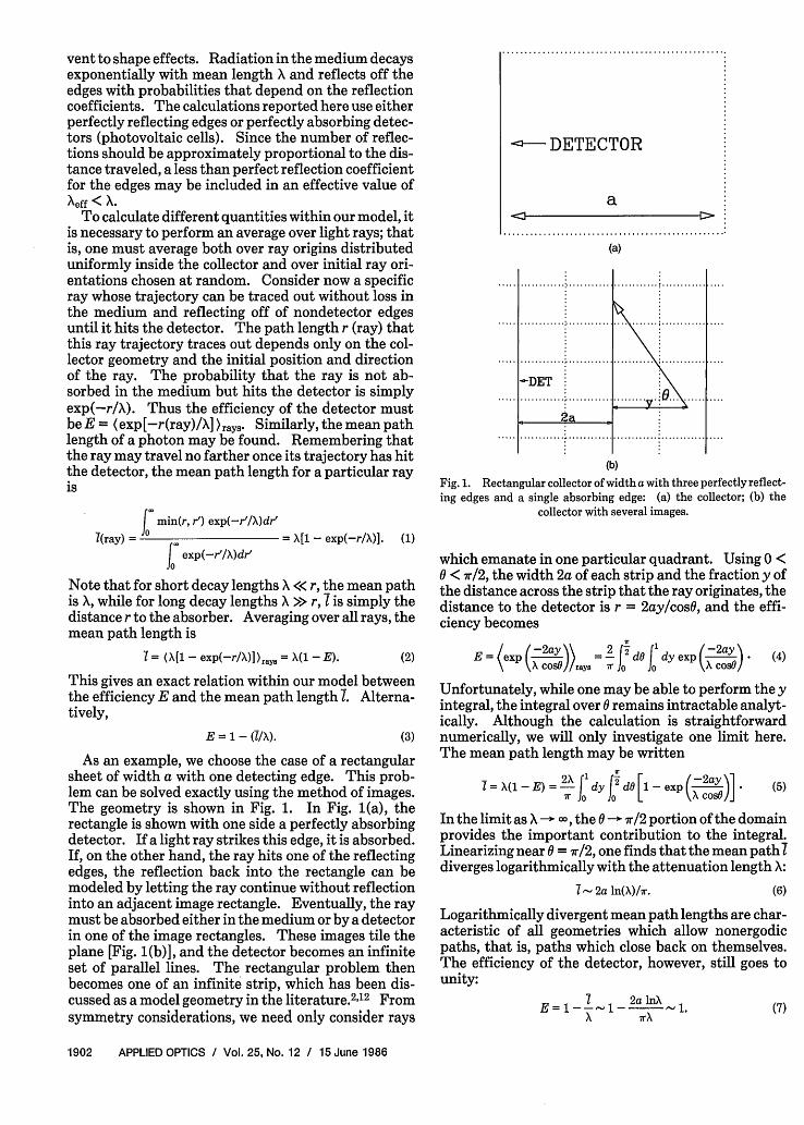
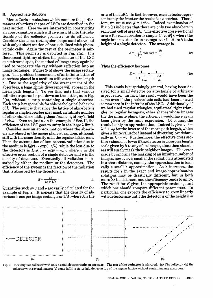
Fig. . Rectangular collector of width a with three perfectly reflect-ing edges and a single absorbing edge: (a) the collector; (b) the
collector with several images.
= X[1 - exp(-r/X)]. (1)J exp(-r'/X)dr'0
Note that for short decay lengths X << r, the mean pathis X, while for long decay lengths X >> r, I is simply thedistance r to the absorber. Averaging over all rays, themean path length is
I = ([1 - exp(-r/X)] )rays = X(l - E). (2)
This gives an exact relation within our model betweenthe efficiency E and the mean path length 1. Alterna-tively,
E = 1-(I/X). (3)
As an example, we choose the case of a rectangularsheet of width a with one detecting edge. This prob-lem can be solved exactly using the method of images.The geometry is shown in Fig. 1. In Fig. 1(a), therectangle is shown with one side a perfectly absorbingdetector. If a light ray strikes this edge, it is absorbed.If, on the other hand, the ray hits one of the reflectingedges, the reflection back into the rectangle can bemodeled by letting the ray continue without reflectioninto an adjacent image rectangle. Eventually, the raymust be absorbed either in the medium or by a detectorin one of the image rectangles. These images tile theplane [Fig. 1(b)], and the detector becomes an infiniteset of parallel lines. The rectangular problem thenbecomes one of an infinite strip, which has been dis-cussed as a model geometry in the literature. 2"12 Fromsymmetry considerations, we need only consider rays
which emanate in one particular quadrant. Using 0 <0 < 7r/2, the width 2a of each strip and the fraction y ofthe distance across the strip that the ray originates, thedistance to the detector is r = 2ay/cosO, and the effi-ciency becomes
exp ( -2ay 2 dO('d -2ay (4)Xcost} rays r o Jo, X cosO
Unfortunately, while one may be able to perform the yintegral, the integral over 0 remains intractable analyt-ically. Although the calculation is straightforwardnumerically, we will only investigate one limit here.The mean path length may be written
= (1-E) =2iI dy J2 d [1-exp ( 2ay (5)Ir fo 0o I x cosA]
In the limit as X -a, the 0 - 7r/2 portion of the domainprovides the important contribution to the integral.Linearizing near = 7r/2, one finds that the mean path 7diverges logarithmically with the attenuation length X:
7 - 2a ln(X)/hr. (6)
Logarithmically divergent mean path lengths are char-acteristic of all geometries which allow nonergodicpaths, that is, paths which close back on themselves.The efficiency of the detector, however, still goes tounity:
1 - _2a lnX
X 7rX(7)
1902 APPLIED OPTICS / Vol. 25, No. 12 / 15 June 1986
I............
.............
.......... V . .....
Ill. Approximate Solutions
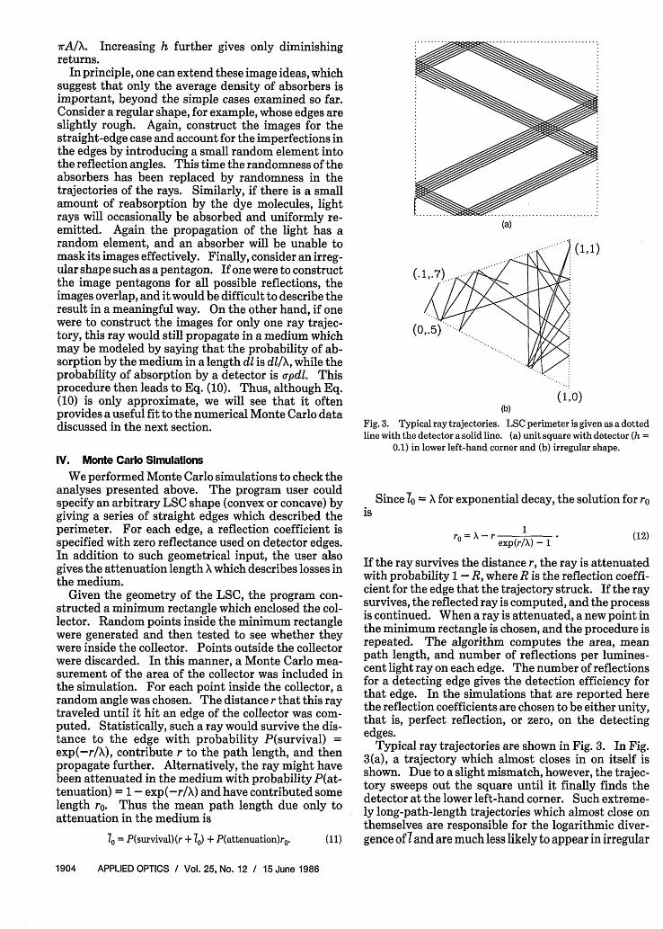
Monte Carlo simulations which measure the perfor-mances of various shapes of LSCs are described in thenext section. Here we are interested in constructingan approximation which will give insight into the rela-tionship of the collector geometry to its efficiency.Consider the same rectangular shape used above butwith only a short section of one side lined with photo-voltaic cells. Again the rest of the perimeter is mir-rored. This geometry is depicted in Fig. 2(a). If afluorescent light ray strikes the perimeter of the LSCat a mirrored spot, the method of images may again beused to propagate the ray without reflection into animage rectangle. Figure 2(b) shows the image rectan-gles. The problem becomes one of an infinite lattice ofabsorbers placed in a medium with attenuation lengthX. Due to the regularity of the arrangement of theabsorbers, a logarithmic divergence will appear in themean path length 1. To see this, note that variousinfinite strips can be put down on the lattice, as in Fig.2(c), without a strip containing a single absorber.Each strip is responsible for this pathological behaviorof 1. The point is that since the lattice of absorbers isregular, a single absorber may mask an infinite numberof other absorbers hiding them from a light ray's fieldof view. Even so, just as in the example of Sec. II, theefficiency of the LSC goes to unity in the large X limit.
Consider now an approximation where the absorb-ers are placed in the image plane at random, althoughstill with the same density as in the regular lattice case.Then the attenuation of luminescent radiation due tothe medium is Io(r) exp(-r/X), while the loss due tothe detectors is Idet(r) - exp(-rap), where is theeffective cross section of a single detector and p is thedensity of detectors. Eventually all radiation is ab-sorbed by either the medium or the detectors. Theefficiency of the system is the fraction of the radiationthat is absorbed by the detectors, i.e.,
E = upt/x * (8)rip + 1/X
Quantities such as a and p are easily calculated for theexample of Fig. 2. It appears that the density of ab-sorbers is one per image rectangle or 1/A, where A is the
1:1
area of the LSC. In fact, however, each detector repre-sents only the front or the back of an absorber. There-fore, we must use p = 1/2A. Indeed examination ofFig. 2(c) indicates that there are only two absorbers ineach unit cell of area 4A. The effective cross-sectionalarea r for each absorber is simply (hi cosl ), where theangle brackets denote an average over 0. Here h is theheight of a single detector. The average is
2r
0-= If2 dh co@=-7 - 7
Thus the efficiency becomes1 1
E_=__= irA
1+-1 +rAXtp Xh
(9)
(10)
This result is surprisingly general, having been de-rived for a small detector on a rectangle of arbitraryaspect ratio. In fact, the result would have been thesame even if the photovoltaic cells had been locatedsomewhere in the interior of the LSC. Additionally, ifwe had used regular triangles, equilateral right trian-gles, or regular hexagons, other shapes whose imagestile the infinite plane, the efficiency would have againbeen given by the same expression. Of course, theresult is only an approximation. Indeed it gives 7-1 =X-' + ap for the inverse of the mean path length, whichgives a finite value for 7 instead of diverging logarithmi-cally as X - a. Furthermore, the effective cross sec-tion a should be lower if the detector is close on a lengthscale given by h to any of its images, since then absorb-ers will surely mask their neighbor images. The errormade by ignoring the masking of an infinite number ofimages, however, is small if the radiation is attenuatedin a short distance, namely, the approximation is basi-cally a small X approximation. As X increases, theresults for I in the exact and image-approximationsolutions may be drastically different, but in bothcases A/X tends to zero and the efficiency tends to unity.The result for E gives the appropriate scales againstwhich one should compare different parameters. Inparticular, one expects the efficiency to grow linearlywith detector size until the detector is of the height h
_1 _ L - - - - - - - - - -/J -1,1 /~~~~~~~~~~~~~~~~~~--Ir-- - _ _ _ _ _v- _ _ -( X . -I
I --- DETECTOR
a..................................................
(a)
I Lt
(b)
I I
(C)
Fig. 2. Rectangular collector with only a small detector strip on one edge. The rest of the perimeter is mirrored. (a) The collector; (b) thecollector with several images; (c) some infinite strips laid down on top of the regular lattice without containing any absorbers.
15 June 1986 / Vol. 25, No. 12 / APPLIED OPTICS 1903
1:1 1:1
7rA/X. Increasing h further gives only diminishingreturns.
In principle, one can extend these image ideas, whichsuggest that only the average density of absorbers isimportant, beyond the simple cases examined so far.Consider a regular shape, for example, whose edges areslightly rough. Again, construct the images for thestraight-edge case and account for the imperfections inthe edges by introducing a small random element intothe reflection angles. This time the randomness of theabsorbers has been replaced by randomness in thetrajectories of the rays. Similarly, if there is a smallamount of reabsorption by the dye molecules, lightrays will occasionally be absorbed and uniformly re-emitted. Again the propagation of the light has arandom element, and an absorber will be unable tomask its images effectively. Finally, consider an irreg-ular shape such as a pentagon. If one were to constructthe image pentagons for all possible reflections, theimages overlap, and it would be difficult to describe theresult in a meaningful way. On the other hand, if onewere to construct the images for only one ray trajec-tory, this ray would still propagate in a medium whichmay be modeled by saying that the probability of ab-sorption by the medium in a length dl is dl/X, while theprobability of absorption by a detector is pdl. Thisprocedure then leads to Eq. (10). Thus, although Eq.(10) is only approximate, we will see that it oftenprovides a useful fit to the numerical Monte Carlo datadiscussed in the next section.
IV. Monte Carlo Simulations
We performed Monte Carlo simulations to check theanalyses presented above. The program user couldspecify an arbitrary LSC shape (convex or concave) bygiving a series of straight edges which described theperimeter. For each edge, a reflection coefficient isspecified with zero reflectance used on detector edges.In addition to such geometrical input, the user alsogives the attenuation length X which describes losses inthe medium.
Given the geometry of the LSC, the program con-structed a minimum rectangle which enclosed the col-lector. Random points inside the minimum rectanglewere generated and then tested to see whether theywere inside the collector. Points outside the collectorwere discarded. In this manner, a Monte Carlo mea-surement of the area of the collector was included inthe simulation. For each point inside the collector, arandom angle was chosen. The distance r that this raytraveled until it hit an edge of the collector was com-puted. Statistically, such a ray would survive the dis-tance to the edge with probability P(survival) =exp(-r/X), contribute r to the path length, and thenpropagate further. Alternatively, the ray might havebeen attenuated in the medium with probability P(at-tenuation) = 1- exp(-r/X) and have contributed somelength r. Thus the mean path length due only toattenuation in the medium is
70 = P(survival)(r + 70) + P(attenuation)ro. (11)
(a)
(-
(1,1)
(1,0)(b)
Fig. 3. Typical ray trajectories. LSC perimeter is given as a dottedline with the detector a solid line. (a) unit square with detector (h =
0.1) in lower left-hand corner and (b) irregular shape.
isSince 10 = X for exponential decay, the solution for ro
ro X-r 1exp(r/X) - (12)
If the ray survives the distance r, the ray is attenuatedwith probability 1 - R, where R is the reflection coeffi-cient for the edge that the trajectory struck. If the raysurvives, the reflected ray is computed, and the processis continued. When a ray is attenuated, a new point inthe minimum rectangle is chosen, and the procedure isrepeated. The algorithm computes the area, meanpath length, and number of reflections per lumines-cent light ray on each edge. The number of reflectionsfor a detecting edge gives the detection efficiency forthat edge. In the simulations that are reported herethe reflection coefficients are chosen to be either unity,that is, perfect reflection, or zero, on the detectingedges.
Typical ray trajectories are shown in Fig. 3. In Fig.3(a), a trajectory which almost closes in on itself isshown. Due to a slight mismatch, however, the trajec-tory sweeps out the square until it finally finds thedetector at the lower left-hand corner. Such extreme-ly long-path-length trajectories which almost close onthemselves are responsible for the logarithmic diver-gence of and are much less likely to appear in irregular
1904 APPLIED OPTICS / Vol. 25, No. 12 / 15 June 1986
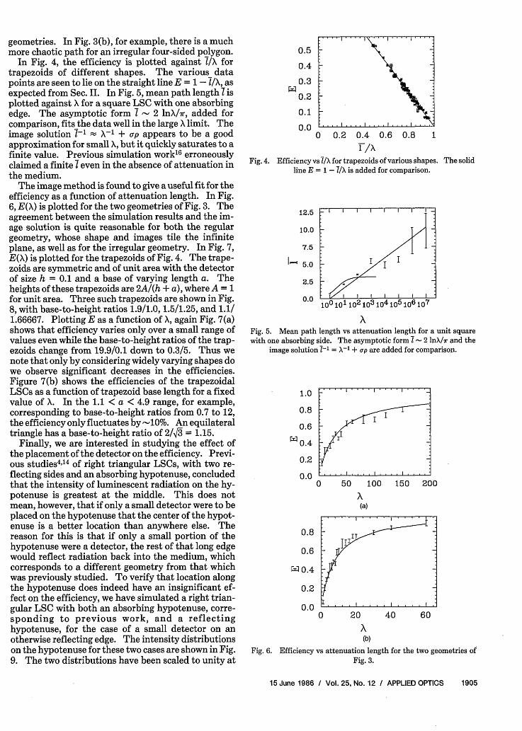
geometries. In Fig. 3(b), for example, there is a muchmore chaotic path for an irregular four-sided polygon.
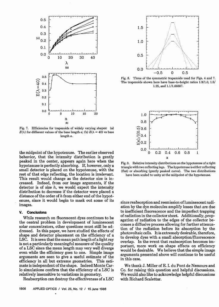
In Fig. 4, the efficiency is plotted against l/\ fortrapezoids of different shapes. The various datapoints are seen to lie on the straight line E = 1 - l/X, asexpected from Sec. II. In Fig. 5, mean path length 7 isplotted against X for a square LSC with one absorbingedge. The asymptotic form - 2 lnX/7r, added forcomparison, fits the data well in the large X limit. Theimage solution -1 - X-' + up appears to be a goodapproximation for small X, but it quickly saturates to afinite value. Previous simulation work'6 erroneouslyclaimed a finite I even in the absence of attenuation inthe medium.
The image method is found to give a useful fit for theefficiency as a function of attenuation length. In Fig.6, E(X) is plotted for the two geometries of Fig. 3. Theagreement between the simulation results and the im-age solution is quite reasonable for both the regulargeometry, whose shape and images tile the infiniteplane, as well as for the irregular geometry. In Fig. 7,E(X) is plotted for the trapezoids of Fig. 4. The trape-zoids are symmetric and of unit area with the detectorof size h = 0.1 and a base of varying length a. Theheights of these trapezoids are 2A/(h + a), where A = 1for unit area. Three such trapezoids are shown in Fig.8, with base-to-height ratios 1.9/1.0, 1.5/1.25, and 1.1/1.66667. Plotting E as a function of X, again Fig. 7(a)shows that efficiency varies only over a small range ofvalues even while the base-to-height ratios of the trap-ezoids change from 19.9/0.1 down to 0.3/5. Thus wenote that only by considering widely varying shapes dowe observe significant decreases in the efficiencies.Figure 7(b) shows the efficiencies of the trapezoidalLSCs as a function of trapezoid base length for a fixedvalue of X. In the 1.1 < a < 4.9 range, for example,corresponding to base-to-height ratios from 0.7 to 12,the efficiency only fluctuates by -10%. An equilateraltriangle has a base-to-height ratio of 2/,/3 = 1.15.
Finally, we are interested in studying the effect ofthe placement of the detector on the efficiency. Previ-ous studies 4 ,'4 of right triangular LSCs, with two re-flecting sides and an absorbing hypotenuse, concludedthat the intensity of luminescent radiation on the hy-potenuse is greatest at the middle. This does notmean, however, that if only a small detector were to beplaced on the hypotenuse that the center of the hypot-enuse is a better location than anywhere else. Thereason for this is that if only a small portion of thehypotenuse were a detector, the rest of that long edgewould reflect radiation back into the medium, whichcorresponds to a different geometry from that whichwas previously studied. To verify that location alongthe hypotenuse does indeed have an insignificant ef-fect on the efficiency, we have simulated a right trian-gular LSC with both an absorbing hypotenuse, corre-sponding to previous work, and a reflectinghypotenuse, for the case of a small detector on anotherwise reflecting edge. The intensity distributionson the hypotenuse for these two cases are shown in Fig.9. The two distributions have been scaled to unity at
0.5
0.4
0.3
0.2
0.1
0.00 0.2 0.4 0.6 0.8
1 /X
Fig. 4. Efficiency vs l/X for trapezoids of various shapes. The solidline E = 1 - A/X is added for comparison.
12.5 _ I I | |
10.0
7.5
0.0: I I100 10 1 o2 103 104 105 106 107
Fig. 5. Mean path length vs attenuation length for a unit squarewith one absorbing side. The asymptotic form I - 2 lnX/7r and the
image solution 7-1 = X-1 + rp are added for comparison.
1.0
0.8
0.6
0.4
0.2
0.00 50 100 150 200
(a)
0.8
0.6
140.4
0.2
0.00 20 40 60
(b)
Fig. 6. Efficiency vs attenuation length for the two geometries ofFig. 3.
15 June 1986 / Vol. 25, No. 12 / APPLIED OPTICS 1905
.. .I - . . ,., -11 |....I....I....I
0.5
0.4
0.3
W0.2
0.1
0.0
II
11
ex:
0.5
0.4
0.3
0.2
0.1
0.0
0 10 20 30 40
(a)
1...,1,,,|,... I .. :
o 5 10 15 20
a(b)
Fig. 7. Efficiencies for trapezoids of widely varying shapes: (a)E(X) for different values of the base length a; (b) E(X = 40) vs base
length a.
the midpoint of the hypotenuse. The earlier observedbehavior, that the intensity distribution is gentlypeaked in the center, appears again here when thehypotenuse is perfectly absorbing. If, however, only asmall detector is placed on the hypotenuse, with therest of that edge reflecting, the location is irrelevant.This result would change as the detector size is in-creased. Indeed, from our image arguments, if thedetector is of size h, we would expect the intensitydistribution to decrease if the detector were placed adistance of the order of h from either end of the hypot-enuse, since it would begin to mask out some of itsimages.
V. Conclusions
While research on fluorescent dyes continues to bethe central problem in development of luminescentsolar concentrators, other questions must still be ad-dressed. In this paper, we have studied the effects ofshape and detector placement on the efficiency of aLSC. It is seen that the mean path length of a light rayis not a particularly meaningful measure of the qualityof a LSC since the mean length may very well divergeeven while the efficiency goes to one. Simple imagearguments are seen to give a useful estimate of theefficiency in all but extreme geometries. This esti-mate is independent of the shape. Indeed Monte Car-lo simulations confirm that the efficiency of a LSC isrelatively insensitive to variations in geometry.
Reabsorption can destroy the effectiveness of a LSC
1.5
1.0
0.5
0.0-0.5 0 0.5
Fig. 8. Three of the symmetric trapezoids used for Figs. 4 and 7.The trapezoids shown here have base-to-height ratios 1.9/1.0, 1.5/
1.25, and 1.1/1.66667.
1.0
0.8
to 0.6
0.40.2
0.00 0.2 0.4 0.6 0.8 1
xFig. 9. Relative intensity distributions on the hypotenuse of a righttriangle with two reflecting legs. The hypotenuse is either reflecting(flat) or absorbing (gently peaked curve). The two distributions
have been scaled to unity at the midpoint of the hypotenuse.
since reabsorption and reemission of luminescent radi-ation by the dye molecules amplify losses that are dueto inefficient fluorescence and the imperfect trappingof radiation in the collector sheet. Additionally, prop-agation of radiation to the edges of the collector be-comes a diffusive process allowing for further attenua-tion of the radiation before its absorption by thephotovoltaic cells. It is extremely desirable, therefore,to develop dyes with a small absorption/fluorescenceoverlap. In the event that reabsorption becomes im-portant, more work on shape effects on efficiencywould be desirable. We believe that the simple imagearguments presented above will continue to be usefulin this case.
We thank J. Miller of E. I. du Pont de Nemours andCo. for raising this question and helpful discussions.We would also like to acknowledge helpful discussionswith Richard Scalettar.
1906 APPLIED OPTICS / Vol. 25, No. 12 / 15 June 1986
:. . . .I. . . .I I I I I I I. . .I. . .I:
7
:.... 1.1_1.1_111.11_111
References1. W. A. Shurcliff, "Radiance Amplification by Multistage Fluo-
rescence System," J. Opt. Soc. Am. 41, 209 (1951).2. W. H. Weber and J. Lambe, "Luminescent Greenhouse Collec-
tor for Solar Radiation," Appl. Opt. 15, 2299 (1976).3. A. M. Hermann, "Luminescent Solar Concentrators: a Re-
view," Sol. Energy 29, 323 (1982).4. A. Goetzberger and W. Greubel, "Solar Energy Conversion with
Fluorescent Collectors," Appl. Phys. 14, 123, (1977).5. J. M. Drake, M. L. Lesiecki, and J. Sansregret, "Organic Dyes in
PMMA in a Planar Luminescent Solar Collector: a Perfor-mance Evaluation," Appl. Opt. 21, 2945 (1982).
6. J. S. Batchelder, A. H. Zewail, and T. Cole, "Luminescent SolarConcentrators. 1: Theory of Operation and Techniques forPerformance Evaluation," Appl. Opt. 18, 3090 (1979).
7. E. Yablonovitch, "Thermodynamics of the Fluorescent PlanarConcentrator," J. Opt. Soc. Am. 70, 1362 (1980).
8. J. A. Levitt and W. H. Weber, "Materials for LuminescentGreenhouse Solar Collectors," Appl. Opt. 16, 2684 (1977).
9. R. W. Olson, R. F. Loring, and M. D. Fayer, "Luminescent SolarConcentrators and the Reabsorption Problem," Appl. Opt. 20,2934 (1981).
10. J. Sansregret, J. M. Drake, W. R. L. Thomas, and M. L. Lesiecki,"Light Transport in Planar Luminescent Solar Concentrators:
the Role of DCM Self-Absorption," Appl. Opt. 22, 573 (1983).11. A. Zastrow, K. Heidler, R. E. Sah, V. Wittwer, and A. Goetz-
berger, Commission of the European Communities, Third ECPhotovoltaic Solar Energy Conference, in Proceedings, Interna-tional Conference, Cannes, France, 27-31 Oct 1980, 413-417,EUR 7089 EN, D (Reidel, Dordrecht, 1981).
12. J. S. Batchelder, A. H. Zewail, and T. Cole, "Luminescent SolarConcentrators. 2: Experimental and Theoretical Analysis ofTheir Possible Efficiencies," Appl. Opt. 20, 3733 (1981).
13. M. L. Lesiecki and J. M. Drake, "Use of the Thermal LensTechnique to Measure the Luminescent Quantum Yields ofDyes in PMMA for Luminescent Solar Concentrators," Appl.Opt. 21, 557 (1982).
14. K. Heidler, "Efficiency and Concentration Ratio Measurementsof Fluorescent Solar Concentrators Using a Xenon Measure-ment System," Appl. Opt. 20, 773 (1981).
15. K. Heidler, A. Goetzberger, and V. Wittwer, Commission of theEuropean Communities, Fourth EC Photovoltaic Solar EnergyConference, in Proceedings, International Conference, Stresa,Italy, 10-14 May 1982, 682-686, EUR 8042 EN (Reidel, Dor-drecht, 1982).
16. J. Roncali and F. Garnier, "Photon-Transport Properties ofLuminescent Solar Concentrators: Analysis and Optimiza-tion," Appl. Opt. 23, 2809 (1984).
Massive Gravitational Lens
Astronomers have detected the influence of an unexpectedly large gravitational lens that is 400 times more
massive than any other observed lens. Another aspect of the newly discovered lens is that (so far)
astronomers are unable to detect the gravity source either with optical or radio telescopes.
A gravitational lens results when light from a distant object is bent as it passes near a strong gravitational
field. The bent light, passing on different sides of the object causing the gravitational field, reaches the
observer from slightly different directions, giving the impression that several objects are being seen. A
gravitational lens is not a new phenomenon. Predicted by Einstein in 1936, the first one was discovered in
1979. Since then, eight others have been reported, including this latest one observed by a team headed by Ed-
win L. Turner of Princeton University. Turner reported the team's finding in a talk at the NSF. The work is be-
ing published in Nature. Others who worked with Turner were Donald P. Schneider of the Institute for
Advanced Study in Princeton; Bernard F. Burke, Jacqueline N. Hewitt, and Glen I. Langston, of Massachusetts
Institute of Technology; James E. Gunn of Princeton; and Charles R. Lawrence and Maarten Schmidt of
California Institute of Technology.The separation between the two images now detected is 157 arc sec compared with 7 arc sec for the
previous largest separation of images (1 arc sec = 1/3600°). What the astronomers observed were two
images of a quasar with identical spectra and redshifts. The quasar from which the light originated is about five
billion light years from earth in the direction of the constellation Leo. The astronomers used the 158-in. MayaI
optical telescope at Kitt Peak National Observatory in Arizona and the Very Large Array, a grouping of 27
antennas in New Mexico that is part of the National Radio Astronomy Observatory. The lens was first detected
on 4 March 1986.
Three possible explanations of the mysterious gravitational lens are offered in the Nature article: a giant
cluster of galaxies; a gigantic black hole with a mass 1000 trillion times that of the sun; a cosmic string, a theo-
retical object that might be left over from the early universe.
15 June 1986 / Vol. 25, No. 12 / APPLIED OPTICS 1907