Embed Size (px)
Citation preview
Review No. 135
Optimización de molinos
de rodillos verticales mediante
la tecnología LV
LV Technology optimises
vertical roller mills
Reprint of article published in Cemento Hormigon,
April 2001.
By Søren Worre Jørgensen, F.L.Smidth & Co A/S,
Denmark.
11143_review_135.qxd 08-11-01 12:06 Side 1
F.L. Smidth ha firmado un acuerdo exclusivo decooperación con la Cía. L.V. Technology Co. Ltd.(LVT), domiciliada en Tailandia, para promocionarla venta del espectacular concepto de optimiza-ción de molinos. La nueva tecnología ha dem-ostrado ser altamente eficaz en la optimizaciónde molinos de rodillos verticales de diferentesfabricantes.
En los últimos tres años LVT ha conseguido mejor-as importantes en la operación de molinos verti-cales: mayor rendimiento, ahorro en el consumode energía específico, funcionamiento más estab-le, es decir: menores vibraciones y optimización dela distribución del tamaño de partículas del pro-ducto final.
Un proyecto de optimización basado en el con-cepto LVT va dirigido a tres áreas:
1. El separador2. La velocidad del aire a través del molino3. El anillo tobera de aire y el cono guía de
aire
1. SEPARADORLa finalidad primordial de la separación de altaeficiencia consiste naturalmente en evitar que
exista material grueso en el fino, y el materialfino en el grueso. Esto se consigue con el separa-dor LVT el cual se asemeja al bien conocido sepa-rador FLS RAR -que se instala en el interior de losmolinos Atox- a pesar de que el diseño de los ála-bes individuales de la celosía, el número de ála-bes, la distancia de la parte extrema de la celosíaal rotor, así como la velocidad del aire entre losálabes sean algo diferentes. Además, el separadorde diseño LVT puede adaptarse a la carcasa y alrotor del separador existentes y difiere, por tanto,del separador FLS RAR en cuanto a altura y diáme-tro de la celosía de álabes y del rotor del separad-or.
2. VELOCIDAD DEL AIREEn principio, el material grueso y fino -que vasuspendido en la corriente de aire que atraviesa elmolino- es clasificado por precipitación en lacarcasa del molino y por separación o clasificaciónen el separador.
En base a que esté bien diseñado, el separador esun sistema de clasificación más eficiente que laprecipitación en la carcasa del molino. Por estemotivo es una ventaja concentrar el proceso declasificación en el separador, haciendo que elmolino trabaje con una adecuada velocidad del
Optimización de molinos de rodillos verticalesmediante la tecnología LV
Por D. Søren Worre Jørgensen, Ingeniero Industrial, Director General de Ingenieríade Cemento, Tecnología de Molienda, de F.L. Smidth - Dinamarca
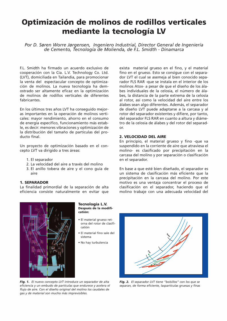
Fig. 1. El nuevo concepto LVT introduce un separador de altaeficiencia y un embudo de partículas que endurece y acelera elflujo de aire. Con el diseño original del molino los caudales degas y de material son mucho más imprevisibles.
Tecnología L.V.Después de la modifi-catión:
• El material grueso ret-orna del rotor de clasifi-catión
• El material fino sale delsistema
• No hay turbulencia
Fig. 2. El separador LVT tiene “bolsillos” con los que seseparan, de forma eficiente, laspartículas gruesas y finas
11143_review_135.qxd 08-11-01 12:06 Side 3
aire en el interior de la carcasa del molino, y queesa velocidad vaya acelerándose a través del mis-mo.
Si esto no ocurriera, una fracción de las partículasde cierto tamaño pueden precipitarse repetida-mente y volver a suspenderse, provocando así unapérdida de carga más elevada en el molino. LVT sededicó a la tarea de conseguir una mayor velocid-ad del aire y una aceleración rediseñando el conode rechazo del separador, así como otras partesinternas del molino. De esta forma, dicho conoactúa también como control de velocidad del aire.
3. ANILLO TOBERA DE AIRE Y CONO GUÍA DEAIREEn la mayoría de los casos, el proyecto de optimi-zación de un molino vertical que prepara LVTincluirá la modificación del anillo tobera de aire ydel cono guía de aire, a fin de optimizar la direc-ción y la velocidad del caudal de aire a través yencima del anillo tobera. El diseño apropiado deestos componentes contribuye de forma significa-tiva al rendimiento del molino, asegurando underrame mínimo y controlado de material a travésdel anillo tobera y una baja pérdida de carga, asícomo una operación más estable.
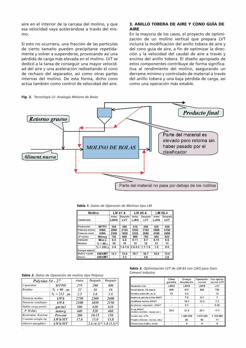
Fig. 3. Tecnología LV. Analogía Molono de Bolas
Tabla 1. Datos de Operacón de Molinos tipo LM
Tabla 2. Datos de Operación de molino tipo Polysius
Tabla 3. Optimización LVT de LM 63 con LSKS para SiamCement Industry
11143_review_135.qxd 08-11-01 12:07 Side 4
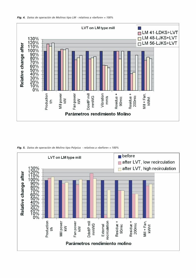
Fig. 4. Datos de operación de Molinos tipo LM - relativos a »before« = 100%
Fig. 5. Datos de operación de Molino tipo Polysius - relativos a »before« = 100%
11143_review_135.qxd 08-11-01 12:07 Side 5
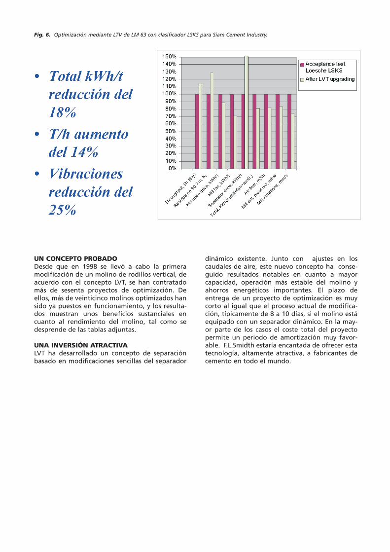
UN CONCEPTO PROBADODesde que en 1998 se llevó a cabo la primeramodificación de un molino de rodillos vertical, deacuerdo con el concepto LVT, se han contratadomás de sesenta proyectos de optimización. Deellos, más de veinticinco molinos optimizados hansido ya puestos en funcionamiento, y los resulta-dos muestran unos beneficios sustanciales encuanto al rendimiento del molino, tal como sedesprende de las tablas adjuntas.
UNA INVERSIÓN ATRACTIVALVT ha desarrollado un concepto de separaciónbasado en modificaciones sencillas del separador
dinámico existente. Junto con ajustes en loscaudales de aire, este nuevo concepto ha conse-guido resultados notables en cuanto a mayorcapacidad, operación más estable del molino yahorros energéticos importantes. El plazo deentrega de un proyecto de optimización es muycorto al igual que el proceso actual de modifica-ción, típicamente de 8 a 10 días, si el molino estáequipado con un separador dinámico. En la may-or parte de los casos el coste total del proyectopermite un periodo de amortización muy favor-able. F.L.Smidth estaría encantada de ofrecer estatecnología, altamente atractiva, a fabricantes decemento en todo el mundo.
Fig. 6. Optimización mediante LTV de LM 63 con clasificador LSKS para Siam Cement Industry.
11143_review_135.qxd 08-11-01 12:07 Side 6
Over the last 3 years LVT has achieved significantimprovements in vertical mill performance, focus-ing on higher throughput, lower specific energyconsumption, more stable operation, i.e. lowervibration, and optimised particle size distributionof the end product.An optimisation project based on the LVT conceptaddresses three key areas:1) the separator2) the air velocity through the mill3) the air nozzle ring and air guide cone.
1. The separatorThe overall objective of high-efficiency separationis of course to avoid coarse material in the finesand fines in the coarse material. This is achievedby the LVT separator which resembles the well-known FLS RAR separator, although the design ofthe individual louvres, the number of louvres, thedistance from louvre tip to rotor and the air velo-city between the louvres are somewhat different.Besides, a separator of LVT design can be adaptedto the existing separator housing and separatorrotor and will therefore deviate from the FLS RARseparator in terms of height and diameter of thelouvre arrangement and the separator rotor.If the mill being upgraded has a dynamic separa-tor, separator drive and rotor shaft are retainedand only the rotor vanes are redesigned.
2. Air velocityIn principle, the coarse and fine material suspen-ded in the air flowing through the mill is classifi-ed by precipitation in the mill house and by sepa-ration in the separator. Provided it is well-desig-ned, the actual separator is a far more efficientmeans of classifying than precipitation in the millhouse. It is therefore an advantage to concentra-te the classifying process in the separator by ope-rating the mill at a suitably high air velocity, andit is also important that the air flow through themill accelerates. Otherwise a fraction of the parti-cles of a certain size range may repeatedly preci-pitate and be resuspended, thus causing higherdifferential pressure in the mill. LVT has addressedthis need for higher air velocity and accelerationby redesigning the separator reject cone andother mill internals. The separator reject cone willthus also act as air velocity control
3. Air nozzle ring and air guide coneIn most cases a vertical mill upgrading projectengineered by LVT will include modification of
the air nozzle ring and the air guide cone to opti-mise the direction and velocity of the air flowthrough and above the nozzle ring. An appropri-ate design of these components contributes signi-ficantly to mill performance by ensuring a lowand controlled material spillage through thenozzle ring, a low pressure drop and more stableoperation.
A proven conceptMore than 60 optimisation projects have beenlaunched since the first modification of a verticalroller mill according to the LVT concept in 1998.More than 25 upgraded mills are now in operati-on, demonstrating the substantial benefits to millperformance as shown by the examples listed inthe table.
An attractive investmentLVT has developed a separation concept that isbased on simple modifications of the existingdynamic separator. Together with adjustments ofthe airflow pattern, this new concept has shownremarkable results in terms of higher capacity,more stable mill operation and substantial energysavings. The delivery time for an upgrading proje-ct is very short and the actual modification processis swift, typically 8-10 days if the mill is equippedwith a dynamic separator. In most cases, the totalcost of the project allows a very favourable pay-back period. F.L.Smidth look forward to offeringthis highly attractive technology to cement manu-facturers around the world.
Fig 1. The new LVT concept introduces a high-efficiencyseparator and a modified grit funnel that streamlines andaccelerates the air flow. With the original mill design gas andmaterial flows are much more unpredictable
Fig 2. Rotor and guide vane arrangement
Fig 3. Ball mill, analogy
Fig 4. Operation data for Mills type LM - relating to"before" = 100%
Fig 5. Operation data for Mills type Polysius - relating to"before" = 100%
Fig 6. LVT Upgrading of LM 63 with LSKS classifier for SiamCement Industry
LV Technologyoptimises vertical roller mills
11143_review_135.qxd 08-11-01 12:07 Side 7

Data in this brochure is intended for preliminary project planning only. Manufacturer reserves the right to modify equipment details and/or specifications without notice.
USAF.L.Smidth Inc.2040 Avenue CBethlehem, PA 18017-2188Tel: +1 - 610-264-6011Tel: +1 - 800-523-9482Fax: +1 - 610-264-6170E-mail: [email protected]
INDIAFuller India LimitedCapital Towers180, Kodambakkam High RoadNungambakkamChennai 600 034Tel: +91 - 44-827-6030/8228623Fax: +91 - 44-827-9393Email: [email protected]
DENMARK F.L.Smidth A/SVigerslev Allé 77DK-2500 ValbyCopenhagenTel: +45 -36 18 10 00Fax: +45 -36 30 18 20Email: [email protected]
www.flsmidth.com
11143_review_135.qxd 08-11-01 12:07 Side 8