Embed Size (px)
Citation preview

Installation and Operating Manual
Lw4: 900mm x 900mm
Model Variations: White and Black
INSTALLERS - PLEASE LEAVE THESE INSTRUCTIONS WITH THE CUSTOMER
6 Years Part Warranty : Please visit www.Lisnawaters.co.uk to regis-ter your 6 years part warranty

Your NOTES & Important Information
Plumber
Name Reg. No.
Company
Address
Tel:
Electrician
Name Part P Reg. No.
Company
Address
Tel:
Warranty No.
Register your warranty on line at www.Lisnawaters.co.uk
Batch No. On side of each packaging box is a 5 digit no. Please supply all that apply

Thank you for purchasing our Lisna Waters Lw4 Shower cabin.
Please Read these fitting instructions to guarantee you get the best out of your LW4.
Please check that the boxes contain all the items listed below, and report to us any parts that are
missing or damaged prior to assembly and within 48 hours of receipt. Damages notified to us after
this time may be chargeable
CAREFULLY CHECK THE PACK IS AS ORDERED:
PARTS LIST
Tick Box 1—Roof/Ceiling (Monsoon shower, speaker, fan and light pre-fitted)
1— Shower Tray / base
2—Glass Rear coloured Panels (Labelled Left and Right)
2—Curved silver top and bottom / frame sections
2—Straight silver frame uprights
2—Curved glass doors
1—Central Column with fitted electronic control panel & Valve
1—Chrome hand shower hoses
1—chrome shower handset
1—Glass shelf Pack includes fittings
1—Shower riser bar and fixings
2—Door handles
1—Pack of door runner wheels (cams)
2— Magnetic door seal
2— ‘U’ profiles glass seals (2 types)
1— Screw and washers pack
4—Waterproof Seals
8—Glass Position Fixtures
2—Hot and Cold WRAS approved Hoses
8—glass holders
Important Notes to Consider
You should ensure that the floor area where the shower is to be situated is level and able to support the weight ofthe LW4 when in use.
Installation requires a qualified plumber to provide the correct connections to water and waste Failure to have theShower installed by qualified Trades men will invalidate your warranty.
Please ensure that all connections are fully water tight, this includes the body jets, monsoon shower, steam genera-tor, water inlets and waste outlets. These are fitted for transport purposes and may become loose or detached.
You may want to fit isolation valves on both hot and cold feeds coming into the bathroom, for future maintenance.
This is a free standing Unit. Please do not attach to any walls. This is necessary to be able to perform the watertightness test at the end of the assembly.
Tools you May need
Electric drill 6mm & 3mm Drill bit and Pilot drill
Spirit Level
Accurate tape measure
Silicone sealant—keep the tip as small as possible to help with neat-ness
Heavy duty scissors
Rubber Mallet
Adjustable Spanner
Philips head screwdriver

Contents
Products Contents List with Images
Importance Notices
Before You Begin
Assembly
Water Connections
Sealing the shower
Final Testing
Completion
Operating Instructions
Safety Precautions
Cleaning and Third Party Product use
Additional information and Help
Thermostatic Cartridge

Lisna Waters Shower Contents
Below is a list of Parts you should have received for the installation of your shower. For easy installation some parts have been pre fitted in place by the factory, such as the monsoon shower head, back jets, etc.
1. Shower Tray / base2. Curved silver top and bottom / frame
sections3. Pre fitted shower valve in column4. Roof/Ceiling (Monsoon shower,
speaker, fan and light pre-fitted)5. Glass Shelf Pack includes fittings6. Magnetic door seal & ‘U’ profiles
glass seals (2 types)7. Central Column with fitted electronic
control panel & Valve8. Curved glass doors9. Side Columns10. Glass Rear coloured Panels (Labelled
Left and Right)11. Glass Fittings12. Handles13. Hand shower and Rail Kit14. Pack of door runner wheels (cams)15. Screws16. Steam generator and control panel
pre fitted
Not Pictured 1. Waterproof Seals2. Glass Position Fixtures3. Hot and Cold WRAS approved
Hoses4. Glass holders5. Chrome hand shower hoses6. Chrome shower handset

Pre—Installation Notes
ELECTRICAL CONNECTIONS
The steam shower unit uses 2.8Kw steam unit with fast start.
Your Electrician should undertake all electrical work under UK Law , This should not be undertaken by anyone who is not a qualified Electrician. This will invalidate you warranty and Home Insurance.
This shower comes with a 13amp plug(s) fitted with RCD unit. This is left for testing purposes and removed to be installed by you electrician, for them to connect as per the current regulations.
(1) Connect within current laws and IP directives.
(2) Wired into isolated IP56 fused feed connecting directly to the house consumer / service box. Remove the Plug and RCD pre fitted and ensure the consumer unit has the capabilities to replace the RCD feature.
Always use suitable protection against electrical surges. A surge protector should eradicate the possibility of either the trans-former or computer control being burnt out, or stop working.
Earthing - Please note earth is required and found on the chassis of the shower tray. If a steam Generator is included a fur-ther earth is required from the Generator unit. This should be grounded as per UK LAW.
Gravity Fed systems If you have a Gravity fed system, then fitting a Shower Pump is recommended. Fitting a Twin Impeller Shower pump rated over 2 bar is necessary as a minimum. Shower pumps MUST be properly sited, installed and commissioned. Incorrectly in-stalled shower pumps will cause adverse affects to your showering and bathing resulting in pulsing or starting and stopping of the pump. If a pump is installed, a separate Mains Cold supply must be fitted and directed to supply the Steam Generator separately (bypassing the pump).
Water requirements This shower requires two water supplies (1 x hot and 1 x cold) tested to be between 1 .5 and 3 bar, with a flow rate over 7.5 litres per minute.
NOTE: We recommend water pressures over 2 bar to achieve optimum showering results. You may want to fit isolation valves on both hot and cold feeds coming into the bathroom, for future maintenance.
Isolating Valves Whilst not a requirement of the showers installation, we would always recommend fitting these as it enables you to turn off the water supply to the shower when not in use (for example going away on holiday). Additionally isolating valves makes service checks easier than locating the house stop cock.
When we use the term DRY RUN we mean you do not silicone anything, just simply construct the shower align, drill and screw everything together. Once happy with the build take the unit apart and carry out the full installation, using your silicone sealer at all points outlined in the manual.

IMPORTANT NOTICE
Before you proceed with fitting your Lisna Waters Shower please read and understand the following:
By commencing testing and installation of the unit you are agreeing to the Terms and Conditions set out by us: copies of which are available by contacting us by email or by telephone (details on the cover of this manual).
You are required to ensure the purchased product dimensions allows for ease of passage to the intended installation area.
Regarding weight tolerances of installation area, it is advisable to contact a builder or refer to Building regulations to
ensure the product placement area has sufficient joist/floor support.
1. It is important that you ensure that your purchase has been delivered undamaged. You are required to check the contents andreport any damage that you feel needs repairing or replacing within 48hrs of receipt of goods. Items reported damaged after this time WILL be chargeable.
2. You are required under the Terms and Conditions to get an electrician to install and connect shower to the mains electric. ByLaw this qualified Electrician must have a Part P registration Number to ensure you meet all UK standard Law and satisfy all legal obligations. You will need to provide this information to guarantee your warranty.
3. Lisna Waters are a supply only company. If you report to us any damage we will send replacements or solutions to remedy theproblem described. We endeavour to fully understand the problem first by asking a series of questions and then propose the solu-tion. We may even ask for digital images to be sent via email to assist the process. The warranty is parts only and does NOT include fitting/inconvenience or other related costs.
4. You are required to ensure that you correctly water test any bath tub before fitting and ensure that you / your fitter fully teststhe unit upon completion and attends to any leaks and faults before he leaves.
5. All hoses, such as to the valve assembly, shower outputs and air switches and waste are fitted for transport purposes and needto be properly sealed and tightened before use. During transportation some connections can become dislodged and therefore break any watertight seal, you are required to ensure that your fitter specifically tests for these possible occurrences and seal/fix accordingly.
6. We recommend you do not book fit until you have inspected the unit upon receipt of the goods. We cannot be held responsi-ble for delays and costs incurred by having to return or ask for replacement parts that need supplying.
7. We cannot be held liable for inconvenience caused due to lack of bathing facilities caused by any delay in receiving yourproduct or whilst awaiting parts.
8. Regarding our sales and technical support: We know our products and their requirements, but we are not qualified plumbers orelectricians and accept no liability for claims suggesting the same. You are advised to check the suitability of the product with a professional body. It is the customer responsibility to ensure the product is fit for purpose.
9. A 'Completion Certificate' is included at the end of the manual where you should record the details of your installers - you willneed this to record your warranty on our website. You MUST register the product warranty within 120 days following delivery

Do not fit the shower into locations where you do not have at least 40cm access all around the cabin both for installation and for future service access.
We advise you do to fit sinks, toilets etc that restrict access behind the shower.
You must ensure you can slide the cabin away from the wall/corner for service access.
Smooth and level walls and floor are required for ideal instal-lation conditions. Avoid carpet or vinyl floors.
Please ensure you have correctly water tested the tub before you continue.
NOTE: The tray base will have a protective film that must be care-fully removed before assembly.
Assembly
NOTE: Instructions shown based on quadrant model, The assembly and operation is identical for off set models except for the rear panels being different sizes.
Please inspect all parts carefully before assembly. BY COMMENCING ASSEMBLY OF THIS SHOWER YOU ACCEPT THAT THE PARTS HAVE ALL BEEN CHECKED AND ARE UNDAMAGED.
This product is fitted with tempered glass. The glass is stronger than regular glass and if it breaks it will form small pieces of cubed glass, not dangerous shards of glass. These small pieces are still sharp, so care must be taken to handle broken glass with care.
If the glass is put under stress or receives a knock or is chipped it will break.
DO NOT ALLOW THE GLASS TO IMPACTED HARD SURFACES OR OBJECTS AS THIS MAY CHIP/WEAKEN THE GLASS.
WEAKENED GLASS THAT IS CHIPPED OR UNDER TENSION MAY SHATTER AT ANY TIME, NOT ALWAYS
IMMEDIATELY.

LEVELING AND FITTING THE TRAY
Remove the protective film covering the base.
Connect the soil pipe, trap and any couplings to the flexible waste under the tub. You may choose tofit either a HEPV0 trap with the appropriate couplings or choose to fit a McAlpine ST28M couplingto a McAlpine 28-NRV trap.
Position the tub base in what will be its final location and adjust the feet until the base is level.
You can raise/lower the feet under the tub and with a spirit level laid across the tub, ensure the tub islevel.
Now fill the base with some water and check that the water flows adequately to the plug and exitssatisfactorily. If the water does not flow to the plug fully, then you will need to increase the fall onthe tray by adjusting the legs. If the water does not exit the waste section fast enough, then ensurethere is suitable fall in the waste pipe and/or no blockage or kinks in the pipe work.
Check and attend to any leaks.
Now slide the tub away from the wall to allow access all around the shower as you assemble.
This product is freestanding so you do not need to fix the feet to the floor you will need to slide outfor future maintenance.
Take your time at this stage an ensure your levels are correct, this will save a lot of time and effortthroughout the build of your unit.

Locate the two silver coloured upright frame sections and the
two curved frame rail sections.
You will need the 8 x LONG screws to join these sections
together.
The upper rail is deeper in height than the lower rail. (please
see image below) You should also see the Lisna water Logo
on the upper Rail.
Align the uprights with the curved rail matching up the two
pre drilled screw holes. The screws will pass through the holes
in the side of the upright and fasten into the curved rail as
shown in the diagram below.
DO NOT FULLY TIGHTEN THE SCREWS—ALLOW
SOME MOVEMENT IN THE FRAME FOR INSTALL-
ING THE FIXED GLASS These will be tightened later after
assembly.
Repeat the process on the other uprights and bottom curved rail until frame is fully assembled as shown
above.
PLEASE NOTE: The uprights will have a cut out section on the bottom, to overhang the trays up stand lip,
these need to be positioned at the bottom.
FRONT FRAME

Fitting Glass Side Panels and Seals
Locate the two fixed glass panels. These are different from
the doors as they do NOT have any holes pre-drilled.
Using the two U shaped rubber seals.
Take one of the U shaped seals and fit over one long edge
of the fixed glass panels That will then be inserted into the
frame. Trim any excess leaving it running the full length of
the glass panel.
Now position this glass panel up to the frame
pushing the long edge of the glass into the upright
of the frame until FULLY bedded into the frame
upright.
This MUST be done from the inside of the frame.
The glass will sit within a lip on the inner surface
of the curved rail both top and bottom.
Repeat this process on the other glass panel.
Now both glass panels are fully inserted into the
uprights you can tighten up the four corners of the
silver framework which will not hold the glass in
position.
DO NOT HIT GLASS WITH HARD
OBJECTS TO PUSH INTO THE
FRAME.
Next you need to fit the Retaining Clips to hold the glass
firmly. Position the clip tight up to the glass on the inside
of the upper and lower rails, mark the position and drill a
small hole then fix a screw to hold the clip in place. Re-
peat top and bottom on both fixed glass panels.
CAUTION WHEN DRILLING - ONLY DRILL
THROUGH THE INNER SINGLE LAYER OF FRAME
Re-fix the SEAL TRIM back on the inside of the lower curved
frame. If removed for easier fit.

Shower Doors FITTING THE SHOWER DOOR WHEEL RUNNERS
Locate the pack of 8 twin wheel shower door runners (cams). There are two different types provided.
With the cam fixed in position, slide on the Chrome finished cover.
Repeat this process of all of the cam wheels.
To fit each of the cams, first select the appropriate cam for the position on the door: 4 x Push button/Quick release for the lower position on the doors. 4x Standard non push button for the upper position on doors.
Position the Cam Body on the outside facing side of the door (curve pointing outwards). Place the clear rubber gasket between the cam body and the glass. The gasket will fit into the hole on the glass.
On the inside of the door, position the grey plastic inner cam body, then washer and bolt.
Now tighten the parts together with the bolt until firmly held in place.

Shower Doors Continued
Before You Hang the Doors you may wish to continue on and hang the doors after The "SEALING THE
SHOWER" Section Of These Instructions. Or fit the doors and remove to hang in place later on once
build has been completed. The doors are designed for easy removal for maintenance and cleaning
purposes.
Hanging the Shower Door
From inside the shower position the upper wheels into the running tracks on the inside curve of the upper curved rail and then let the door hand down.
From outside the shower, move the door to what would be a closed position and press the quick release buttons on the top of the lower cams and move the wheels to fit into the lower runner tracks. Repeat for the other door.
DOOR STOPS
On the inside curve of the upper and lower rail there may be some holes pre-drilled. Fix each of the 8 door stops at these locations with the provided screws. The stops also have a grey cap to cover the screw in the stopper of each —these simply push into place. (sometimes these are pre-fitted at the factory)
FITTING THE DOOR HANDLES
Each of the two shower doors requires a pair of chrome finished door knobs to be fitted. The knobs will be supplied in pairs. Unscrew a pair of knobs and you will see that one side has a long thread.
Once apart, pass the thread through the hole in one of the shower doors and tighten the other knobs on the other side of the glass to it. Tighten until secure. DO NOT OVER TIGHTEN.

Fitting the Rear Panel panels
We recommend you dry fit first - Dry fit is Not adding silicone making
sure everything aligns and fits together correctly first. Silicone is very
hard to remove once applied if done incorrectly.
Locate the two rear, framed glass panels. Each is marked (LEFT or RIGHT). The flat edge should be on the inside to fit up against the centre control panel and the “T” end is to be place on the outside to connect to the glass frame work.
Now position the Central Tower Panel between the rear panels Aligning the holes on the rear panels to those in the tower and fix in place with the screws provided.
Using 8 of the shorter screws, fix the rear glass panel to the central tower. DO this on both long sides of the tower.
NOTE: A bead of sealant can be run between the back panels and Centre Column to provide an extra level of water protection.
Wipe off any excess so none will be 'on show' inside the cabin.
TIP: Only fit each screw loosely at first to allow
enough movement to locate every screw hole.
Once all screws are located in place, then
tighten each screw up fully.
The hand shower comprises of:
Multi function hand show
Chrome finished riser bar
Hand shower holster
Chrome water hose
Rear retaining nut
Fitting screw
The lower part of the riser bar has a threaded water connection. Position this part through the larger hole on the rear glass panel. Fit the rear fixing nut from the rear of the shower to hold in place. Secure the upper part of the riser bar with the screw provided. Tighten both until secure. Connect the silver hand shower hose to the riser bar and the other end to the hand shower head.

Assemble the shelf fully before fitting into the shower.
Position the lower chrome rail over the holes in the glass on the underside of the shelf with the silver grommets positioned between the two. On the upper side of the glass, pass the bolt through a washer and through the hole in the glass and fasten into the end of the lower rail. Repeat the previous step on the other end of the lower rail so that the rail is securely fixed in place.
Take the two silver caps and fit them over the ends of the washer and bolt to provide a clean finish.
The upper rail pushed over the glass from the front. Using a flat head screwdriver, tighten up the fixing point of the front rail, which is located on the underside.
Position the two fixing brackets onto the inside of the rear panel of the shower in the holes provided. Fix the brackets at the rear of the shower with the supplied bolts and washers.
Place the glass of the shelf centrally into the slots of the brackets and then tighten the fixing points on the underside of the brackets to hold the shelf in place. DO NOT OVER TIGHTEN THE BRACKET CONNECTIONS AS THIS MAY BREAK THE GLASS.
Shelf Assembly
Temperature SensorThis steam shower model is fitted with a temperature sensor that monitors the internal cabin temperature. The temperature is selected on the control panel. When the internal cabin temperature reaches the predefined temperature it stops steam production until the temperature falls below, where upon it re-activates the steam production again. The steam sensor should be fitted from the rear of the shower. Just below the control panel you will see a small silver gromit. This is where the head of the sensor will project into the shower. From the rear of the shower, locate the black cableof the temperature sensor. It has a silver tip. Push the silver tip into the rear of the gromit so that itshead protrudes into the cabin. Now fix in position with a very small amount of silicone.
Temperature Sensor

Carefully lift the three joined rear sections onto the tray into position.
A bead of sealant along the tray where the panels will sit will provide a watertight barrier.
Remember to remove any excess sealant once the panels have been seated into position.
DO NOT SCREW THE PANELS TO THE TRAY JUST YET.
Frame and Panels Get fitted to Tray
Place the completed front frame section onto the front of the shower tray and align the uprights with the rear glass panels so that the fixing holes line up.
Standing behind the shower locate the screw holes that attach the back panels to the front glass frame. Using 8x short screws - screw into the back panels towards the front frame.
NOTE: A bead of sealant can be run between the between the back panels
and Front Frame work to provide an extra level of water protection.
Simply wipe off any excess so none will be 'on show'
Fixing the Back Panels to the tray - at the bottom of the back panels there is a lip that has holes to enable the Short screws to fasten the rear glass panels to the tray.
After Dry Fit repeat all the steps adding the
silicone and wiping away excess to ensure you
have a neat seal between each section.

Fixing the Roof to the Cabin
The Speaker, fan and light will be pre-fitted.
Remove the protective film from the roof/ceiling.
The white ozone is supplied separately and will need to be fitted. Unscrew the chrome end from the main body of the ozone, position the ozone unit on the outside of the shower on the roof as shown opposite. Screw on the chrome end on the inside of the shower, to hold it in place. The Ozone will be located over the hole in the roof towards the back corner.
If not already pre-fitted, fit the monsoon rain shower head into the centre of the roof. It is held in place with a retaining nut located on the outer/ upper face of the roof.
Put the roof on the enclosure and attach it using to 30mm nuts and Bolts. Pass the top shower head fit-tings through the roof panel and affix using the large nut for this.

Completing the Enclosure Assembly
This shower comes with 4 flapped shower seals that are in two different lengths.
SHORT FLAPPED The shorter flapped seals fit onto the end of the fixed glass panels.
LONG FLAPPED The longer flapped seals fi t onto the trailing edges of the doors.
The seals are not designed to touch the glass, but when the doors are closed they meet so that water is unlikely to escape
MAGNETIC The magnetic seals fit onto the doors where they meet.
Ensure all seals are fully fitted onto the glass, especially the magnetic seals, so that they form an even seal.

Water Connections
This product requires a hot and cold water supply. Your Hot and Cold water supply pipes should ideally be finished about 1 meter above the floor centrally in the corner and finished with 15mm compression isolating valve. The shower will require two braided flexible hoses that connect to these water supply pipes from the shower valve.

The shower valve can be accessed from the rear of the shower and is located on the central tower.
The valve is divided into three parts that are joined to-gether.
The uppermost part is the diverter. There are three connections able to be made here. One to the overhead shower from the outlet pointing upwards, the right hand outlet will be pre-connected to the body jets and finally the left hand connection needs to be made to the hand shower riser bar inside the cabin.
When making the connections, ensure they
are water tight. Check all pre-fitted hoses as
these may only be hand tight during
manufacture
The middle part of the valve handles the water on and off . There are no connections to be made here.
The lower part of the valve has three connections for the hot and cold water supplies into the valve. These are to be connected to the water supply pipes behind the shower and down to the steam unit.
Cold Water IN from the shower valve connects to the Steam Generator (your steam generator may look different than the image opposite, but the connections are marked the same).
The STEAM OUT connects to the rear of the Steam Pod via the INSULATED HOSE to supply Steam into the shower.
Waste/Drain allows un-used water in the generator after it is used, to exit into the underside of the Plug Waste via a thin grey hose.
Water Connection continued
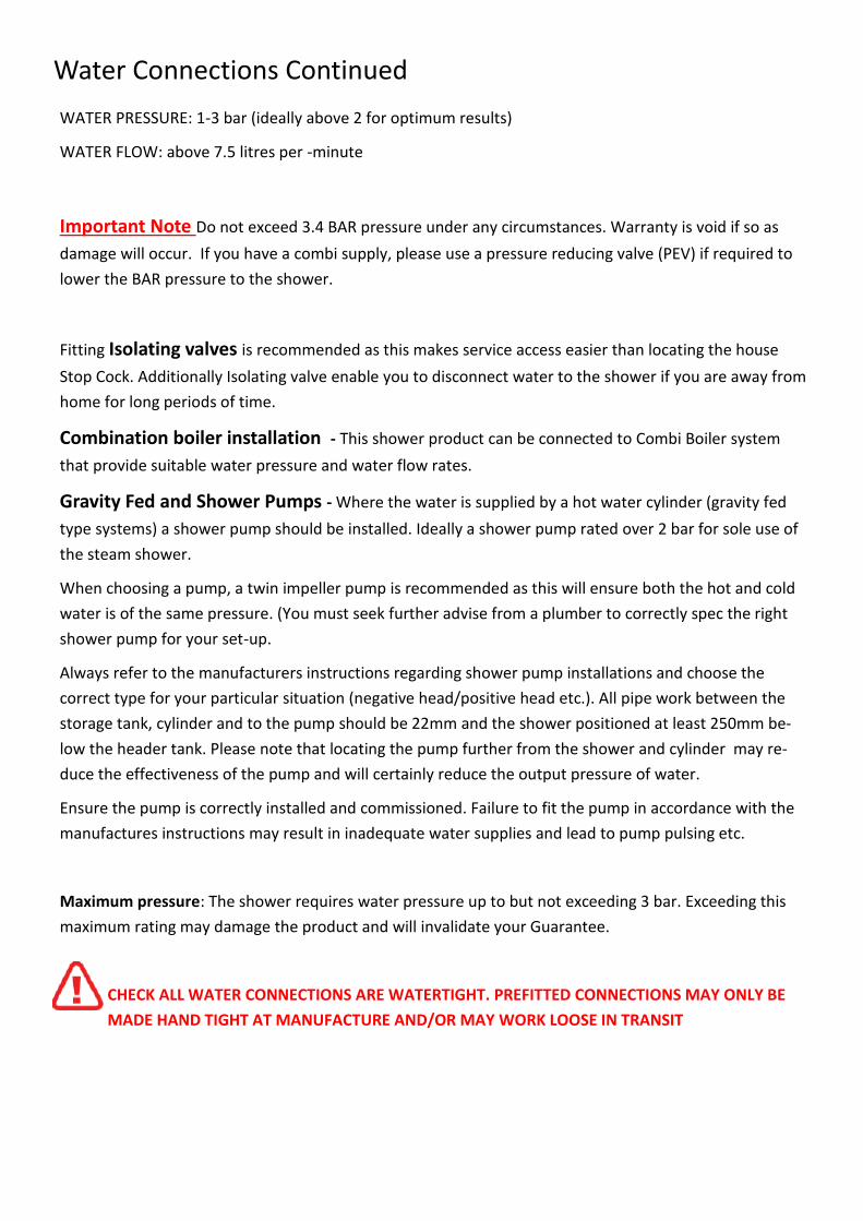
Water Connections Continued WATER PRESSURE: 1-3 bar (ideally above 2 for optimum results)
WATER FLOW: above 7.5 litres per -minute
Important Note Do not exceed 3.4 BAR pressure under any circumstances. Warranty is void if so as damage will occur. If you have a combi supply, please use a pressure reducing valve (PEV) if required to lower the BAR pressure to the shower.
Fitting Isolating valves is recommended as this makes service access easier than locating the house Stop Cock. Additionally Isolating valve enable you to disconnect water to the shower if you are away from home for long periods of time.
Combination boiler installation - This shower product can be connected to Combi Boiler system that provide suitable water pressure and water flow rates.
Gravity Fed and Shower Pumps - Where the water is supplied by a hot water cylinder (gravity fed type systems) a shower pump should be installed. Ideally a shower pump rated over 2 bar for sole use of the steam shower.
When choosing a pump, a twin impeller pump is recommended as this will ensure both the hot and cold water is of the same pressure. (You must seek further advise from a plumber to correctly spec the right shower pump for your set-up.
Always refer to the manufacturers instructions regarding shower pump installations and choose the correct type for your particular situation (negative head/positive head etc.). All pipe work between the storage tank, cylinder and to the pump should be 22mm and the shower positioned at least 250mm be-low the header tank. Please note that locating the pump further from the shower and cylinder may re-duce the effectiveness of the pump and will certainly reduce the output pressure of water.
Ensure the pump is correctly installed and commissioned. Failure to fit the pump in accordance with the manufactures instructions may result in inadequate water supplies and lead to pump pulsing etc.
Maximum pressure: The shower requires water pressure up to but not exceeding 3 bar. Exceeding this maximum rating may damage the product and will invalidate your Guarantee.
CHECK ALL WATER CONNECTIONS ARE WATERTIGHT. PREFITTED CONNECTIONS MAY ONLY BE
MADE HAND TIGHT AT MANUFACTURE AND/OR MAY WORK LOOSE IN TRANSIT

Connections to the Control Panel and Electrics
CONNECTING LIGHTS, FAN, OZONE Etc. Each component needs to be connected to the Electronic Control Unit. Each component (Fan, Ozone, Speaker etc.) has a thin 12v cable with a plug on the end. You will also see that each cable has a sticker with an Icon to indicate what it is.
The electronic control unit behind the showers central tower panel has a large number of cables. Again, each of these cables has a similar corresponding connector plug and a label corresponding to those of the Fan, Ozone, Lights etc. Match each item and make the connection securely.

Continued Connections to Control Panel
AERIAL Position the Radio aerial wire in a position that allows the radio to revive the best possible signal. Note that local interference from Taxis, Ham Radio, Emergency Service, Hospitals etc may affect reception.
ELECTRONIC CONTROL PANEL The Shower has an electronic control panel to allow you to operate and control the steam produc-tion, lights, radio and audio system. Locate the communication cable coming from the panel at the rear of the shower and connect it to the corresponding cable that will be found coming from the elec-tric control unit. This connection uses a series of small pins inside, CARE MUST BE TAKEN MAKING THIS CONNECTION to not bend the pins. The plugs are marked with an ARROW to identify which way they connect.
STEAM GENERATOR & ELECTRONIC CONTROL UNIT This model has a separate Steam Generator and Electronic Control Unit. Both parts have a Data Cable to provide electrical communication between each part and a Power transfer connection. Make these connections and ensure they are secure.
MAIN POWER This Steam Shower requires connections to MAINS ELECTRICITY.
1 x 13amp
The Shower is delivered with a standard 3 pin plug on the end of the power cord. This is for TESTING purposes only.
For final fix this product MUST be connected via an ISOLATED FUSED SPUR. This work requires the services of a Qualified Part P Registered Electrician.
RCD (Residual Current Device) This shower product also comes pre-fitted with an RCD. This device provides safety cut of in case of an electrical fault.
If the Main Board (Consumer Unit) in the property is already RCD protected you MUST remove the one fitted to this product.

Sealing Shower
With the nature of the design of this Lisna Waters shower, there should not be any excess amount of silicone on display. This Lisna Waters shower should not leak when used at home is a normal standard showering use/practices without silicone on show. There should not be any escape of water over the shower tray Rim edge when used under normal showering practise. The design of the shower tray drainage channels will allow areas of the shower to pass any of the excess water, that gains access to the outer tray channel outside the glass enclosure this will then return around the outer rim and drain back through these drainage channels back into the shower tray tub to be safely drained via the usual shower tray waste.
PLEASE NOTE: The shower is made up of solid parts (glass, metal, Acrylic) Any leaks found during testing will be down to incorrect sealing - you should spend a good amount of time water testing the shower before 'signing it off' with the customer.
The Shower Panels should not be directly sprayed with any of the shower functions (ie hand shower or jets etc) as this is inconsistent to normal standard showering use. Doing so may overwhelm the outer tray rim and drainage channels causing excess water on to escape on to the bathroom floor. This Lisna Waters shower should not leak when used at home in a normal standard showering matter/practice without any silicone on show.
However, if you wish to obtain a further level of excess water security you can this by applying additional silicone sealant as required, you should always water test and add any further silicone sealant as required as you continuously test to gauge the level of sealing required to meet your requirement
Please Do Not Apply Silicone to the Water Drainage Channels
Please Do Not Apply Silicone to the Drainage ChannelsAfter allowing the sealant to set (as per the sealant directions), water test the shower and check for signs of water leaking, please attend to them as required.

FAULT FINDING Water does not exit tray fast enough. The tray must be levelled and a suitable ‘fall’ on the tray that enable the water to run to the plug. Addi-tionally, the waste hose (under the tray) should have suitable fall to allow water to exit quickly. Water pressure / flow is low on some or all shower options. Check all the hoses are not trapped or kinked and thus restricting flow. Check also that any washers are not out of position and restricting flow. Ensure you have OVER 7.5 litres per minute flow and over 2 bar water pressure.
Water is ‘pulsing’ . If a pump has been used to supply water under pressure and the back jets, or hand shower cause the pump to start and stop (PULSING WATER), remove the NON RETURN VALVES. Remove the Braided hoses at the rear of the shower. Look inside the valve where the hoses connected and you will see a silver coloured ‘C’ clip. Remove this and this will enable the NRV to be removed (white plastic item). Re-fit the hoses and re-test. Pulsing may also be noted where a pump has not been fully commissioned and there is air in the system
Doors do not meet correctly and or bind when opening or closing. Adjust the door runner cam wheels correctly to enable smooth running and operation.
Water is leaking out of the shower. Dry the shower fully. Once dry, turn on the shower and operate the functions and look for where the water is leaking from. Apply sealant to the area where the water is leaking from.
The shower temperature is low. If the water in the rest of the house is at a suitable temperature, then you may need to replace the thermostatic cartridge. Lime scale or other dirt can impair the function of the cartridge.
Final Testing Check and test that each outlet function (hand shower, body jets and monsoon) work as expected by rotating the DIVERTOR DIAL (top chrome dial).
Check the ON/OFF dial enables the water to be fully on or off in the position indicated on the valve markings.
Check the Temperature can be increased and decreased by turning the lower chrome shower valve dial. Test that the button can be pressed at 38 degrees to turn the dial to the hottest settings.
Check the water runs to the waste/plug efficiently. A small amount remaining in the tray is normal.
Safety Perceptions When using Steam showers it is normal for the steam generator to get quite hot during use. Please allow up to half an hour for the generator to cool before touching associated areas including the steam pod.
Always disconnect or isolate the water supply to the shower before commencing any investigations, service or replacement of parts. Where the product has electrical power, this should also be turned off .
Children should NOT use the shower unless under strict adult supervision.
All products are single person occupancy unless otherwise sold as twin person.
The tray surface inside the product can become slippery especially if soap, gel or shampoo is on the surface, we therefore advise care when stepping in, out and during use.

Operation Manuel
Shower Valves
There are 3 control dials inside your Shower Cabin. These dials con-trol the output functions, water flow and temperature of your shower.
The top dial can be turned to allow you to choose which output you wish to use: Body Jets, Overhead (Monsoon) Shower and Hand Shower. Turn the dial to the required output, there will be an audi-ble click as the selection is made. Do not turn the dial when water is flowing as this will decrease the life of the selector mechanism.
The middle dial adjusts the water flow rate. The dial rotates though 90 degrees. This dial also acts as the on/off for water flow.
The lower dial controls the temperature. The dial rotates from 20 degrees to 38 degrees and then will stop. This is a safety feature. To enable temperatures higher than 38 degrees, simply press the knob on the dial in (toward the main dial) and then turn the dial past the 38 degree mark.
Turning the temperature dial past 30 degrees MUST be done with care to prevent scaling.
Cleaning
This shower should be cleaned after every use to remove the build up of dirt and bacteria. We would recommend that after normal showering use, that the cabin doors are left open until the inside is fully dry. This will help prevent the build up of soap scum, dirt and bacteria.
The shower cabin can trap dirt in gaps between joints of panels etc., which may require extra care and attention during cleaning. To minimise dirt build up between panels, the application of a bead of silicone sealant suitable for shower/bathroom use will fill the gap leaving a smooth finish and both stop dirt build up and offer an extra level of water tightness.
The shower cabin can be cleaned with any suitable cleaning solution that is not abrasive, and is recommended by its manufacturer for use on acrylic, chrome and glass surfaces as appropriate to the materials in the shower. Not all general bathroom cleaners are designed for use on some materials of this product. Harsh abrasive cleaners containing bleach or peroxide MUST NOT be used
DO NOT USE CIF OR OTHER ABRASIVE CLEANING PRODUCTS ON THIS SHOWER.
In hard-water areas, wash down the unit and remove the dirt periodically. Fitting a water filtration device is also advisable in areas where the water is likely to lead to a build up of minerals within the pipes and diverter assembly. Hard water WILL reduces the life of the Parts that come into contact with water, such as the Thermostatic Valve. Fitting water softening devices will prevent this.

Electronic Control Panel Your steam shower is fitted with an electronic control panel that allows you to operate the electronic features of your shower.
From the control panel you can control the lights, Steam, Radio and Bluetooth audio.
POWER ON / OFF In standby mode this button is lit Red.
Press and keep pressing the power but-ton until the panel beeps and the light turns Blue. The Panel is now active.
LIGHTS This model comes with an LED “halo” ring light surrounding the monsoon. Press the light button. With each press, the display will show ON1, ON2, ON3, OFF. The panel is able to accept up to three different light relays, hence the various light modes. Toggle to OFF to turn the light off
STEAM Pressing the Steam button activates the steam Generator.
Press the M button to toggle be-tween the Temperature and Dura-tion/Time settings. Temperature set-ting - is to maintain the heat inside the cabin and duration is the length of time you plan to use the steam. Do NOT use the steam function for longer than 15 minutes in a session, allowing to fully cool before re-use.
FAN The circulation fan can be activated to draw air/steam inside the cabin out. This may be used in conjunction with the steam.
RADIO This button activates the built in FM Radio. In this mode the power button will be lit White. Pressing the TUN TEL button and then using the ARROW buttons allows you to change radio frequency.
REMOVE PROTECTIVE FILM ON CONTROL PANEL BEFORE USE
BLUETOOTH Pressing this button will allow you to receive audio played from Bluetooth enabled device. You can control vol-ume and skip tracks as described for the USB option. You will have to PAIR the shower to a Bluetooth device first - see following page. When this mode is activated then Power button will be lit Red.
OZONE Close the shower doors and press the Ozone button. Leave the shower to carryout the process which takes approximately 10 minutes. Then open the doors and allow the shower to fully air dry. This device does not make any audible or visual notifica-tion other than on the panel display, but there may be an aroma of Ozone when you open the doors. The Power button flashes during this process.
ARROWS The Arrow buttons control Tuning, Volume, Track Skip etc. depending upon which mode is currently se-lected.
TUN TEL
Pressing this button will allow you to enter the tuning mode when the Ra-dio is activated. The current fre-quency will be displayed and by using the Arrow keys can adjust the precise frequency.
M
The button can be used to Store Radio stations into Memory. The button also serves as a toggle the function of the ARROW keys for time/temperature/track/volume/tuning etc.

Bluetooth Pairing
Using Essential Oils in the Steam Pod (not available with Tri-Jet Steam Showers)
Where products are being used to infuse the steam in the steam pod, only products that are designed for such use should be used. The use of products not designed for infusing of steam may lead to damage to this product inducing but not exclusively, discoloration to the pod, tray base and or cabin walls. Products such as, but not exclusive to Olbas Oil is an example of this.
Essential Oils, whilst no noted damaging effects have ever been reported on the materials of the products, Essential oils can be aggressive toward rubbers and plastics when in direct contact. Damage such as cracking, crazing, discoloration, therefore are NOT covered by Guarantee where oils have been used.
Before you can start streaming Audio to your shower you must first establish a connection between the shower and the device that will stream the audio to the shower; this is called
Pairing. You can stream up to 10 meters away, depending upon interference of walls etc.
Most devices that are Bluetooth Audio Streaming enabled can be connected to the shower, such as Smart Phones (Andriod, iPhone etc.), Tablets (Galaxy Tab, iPad etc.) and even computers and
Laptops.
1: Press the BLUETOOTH Button on the control pad. The display will now say BT.
2: On your Smartphone/Tablet etc., go to the Bluetooth settings (If unsure, refer to your manual for more information on how to access this)
3: Ensure Bluetooth is active/running on your device.
4: Initiate a SEARCH/SCAN for New Devices to Pair to.
5: After a small amount of time you should see the device name of the shower appear “ SPROUT”. Select this to complete the Pairing of the two devices.
You are now ready to stream audio. Go to your music playing App, choose a track and press play.
Once Paired you can stream music at any time to the shower. Only once device can be Paired at any time.
Due to the various different number of devices that have Bluetooth, and the variations on the implementation of Bluetooth enabled in your device we are unable to guarantee con-nectivity or to provide support for connecting, however the product has been tested on a number of Apple and Android Tablets and Phones with complete success.
Safety Precautions On models fitted with Steam functions, it is normal for the steam generator to get quite hot during use. Please allow up to half an hour for the generator to cool before touching associated areas including the steam pod.
Always disconnect or isolate the water supply to the shower before commencing any investigations, service or replacement of parts. Where the product has electrical power, this should also be turned off .
Children should NOT use the shower unless under strict adult supervision.
All products are single person occupancy unless otherwise sold as twin person.
The tray surface inside the product can become slippery especially if soap, gel or shampoo is on the surface, we therefore advise care when stepping in, out and during use.

First remove the 3 Chrome Dials from the valve. The
Selector Dial and ON/Off Dial are removed by
unscrewing the Chrome Lug on the side. Once
removed this should also come free with the
threaded grub screw part in place, so the dial will
now pull off. The Temperature Dial has a small sil-
ver cap on the opposite side to the Lug. Remove this
cap and insert a 2.5mm Allen Key inside to the grub
screw. Turn a small amount to loosen (not remove)
and then pull the dial away.
Next unscrew each of the Chrome Dial plates. Now
position the valve from the rear of the central panel
to align with the holes and push through the holes.
Re-fit each of the Chrome Dial Plates from the
front of the panel. This will now hold the valve in
position.
Adjustment can be made to the rear nuts to allow
the valve to be seated correctly against the panel.
Now you can re-fi t each of the chrome dials,
remembering to fi t the lower (thermostatic con-
trol dial) on the lower most position.
Additional fitting Instructions
Fitting the Thermostatic Shower Valve
The Thermostatic Shower Valve is pre fitted into the central tower panel into the three pre-drilled,
vertical holes available for it. If this becomes faulty or needs replacing you may need to fit a new one.
Now the valve is in position and tight you can fit the two WRAS
approved, Braided hoses to the water inlets at the bottom of the
valve in preparation for connecting to water at a later stage.
Connect also the silver/grey hose from the overhead shower that is
pre-fitted to the upper part of the central panel. Ensure this con-
nection
Reverse the process to remove.

Removing the Thermostatic Cartridge
Your shower is fitted with a Thermostatic Cartridge. Should you need to remove or replace the cartridge for maintenance or replacement, follow the instructions below.
Q: I am having to turn the dial round as far as it will go to the hottest setting and the water is
only just warm.
A: Your Thermostatic Cartridge has showed signs of failure. You will need to replace the
Cartridge.
Q: Why did my Thermostatic Cartridge fail?
A: Hard Water areas will result in calcification, which will build up in the Cartridge. Other
reasons might be age of the Cartridge or even dirt or debris collecting in the Cartridge from
the pipes.
BEFORE STARTING ENSURE THAT THE WATER SUPPLIES ARE DISCONNECTED OR ISO-
LATED
It is imperative that the water supply to your shower in between 1 and 3 bar as exceeding this may
damage the Thermostatic Cartridge.
From inside the shower, on the lower of the three dials,
remove the chrome coloured plastic cap that is fitted on
the opposite side to the chrome lug.
The chrome cap will just pull off .
Keep the cap safe.
Using a 2.5mm Alan key, insert this into the hole where
the chrome cap was fitted and loosen the grub screw
about 1 turn to loosen.
DO NOT UNSCREW FULLY.
Now remove the chrome dial.

With the Chrome dial removed you will see a plastic
ring covering with the Thermostat underneath.
Note down the position the ring is placed in.
Pull the plastic ring (Temperature safety lock)
towards you to remove.
Keep this part safe
You will now see the head of the Thermostat
clearly visible.
Turn the head of the cartridge counter-clockwise to
remove.
To fit your new Thermostat, simple reverse this
process.