Embed Size (px)
Citation preview

LyonSE&N – ElyT Workshop 2020 IARI
Abstract Book Lyon Saint Etienne & Nippon Scientific Network
Engineering sciences Lyon Tohoku
LyonSE&N – ELyT Workshop 2020
DOMAINE LOU CAPITELLE, Vogüé – FRANCE
February 17th to 19th, 2020
LyonSE&N – ELyT – IARI Workshop 2020 – 11th annual workshop February 17th-19th, 2020 – Vogüé, Ardèche, France
P a g e 2 | 88
Program of LyonSEN – ELyT Workshop 2020
DOMAINE LOU CAPITELLE, Vogüé – FRANCE February 17th to 19th, 2020
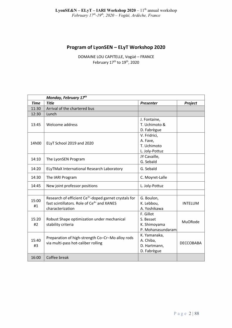
Monday, February 17th Time Title Presenter Project 11:30 Arrival of the chartered bus 12:30 Lunch
13:45 Welcome address J. Fontaine, T. Uchimoto & D. Fabrègue
14h00 ELyT School 2019 and 2020
V. Fridrici, A. Fave, T. Uchimoto L. Joly-Pottuz
14:10 The LyonSEN Program JY Cavaille, G. Sebald
14:20 ELyTMaX International Research Laboratory G. Sebald
14:30 The IARI Program C. Moyret-Lalle
14:45 New joint professor positions L. Joly-Pottuz
15:00 #1
Research of efficient Ce3+-doped garnet crystals for fast scintillators. Role of Ce4+ and XANES characterization
G. Boulon, K. Lebbou, A. Yoshikawa
INTELUM
15:20 #2
Robust Shape optimization under mechanical stability criteria
F. Gillot S. Besset K. Shimoyama P. Mohanasundaram
MuORode
15:40 #3
Preparation of high-strength Co−Cr−Mo alloy rods via multi-pass hot-caliber rolling
K. Yamanaka, A. Chiba, D. Hartmann, D. Fabrègue
DECCOBABA
16:00 Coffee break

LyonSE&N – ELyT – IARI Workshop 2020 – 11th annual workshop February 17th-19th, 2020 – Vogüé, Ardèche, France
P a g e 3 | 88
Monday, February 17th Time Title Presenter Project 16:00 Coffee break
16:30 #4
Piping system, risk management based on wall thinning monitoring and prediction
T. Takagi, P. Guy PYRAMID
16:50 #5
Upscaling of a thermomagnetic generator based on magnetic shape memory alloys
L. Seigner, J. Joseph, M. Lallart, H. Miki, M. Kohl
MISTRAL
17:10 #6
Signal evaluation of electromagnetic pulse-induced acoustic testing for adhesive bonding
H. Sun, H. Kosukegawa, T. Takagi, T. Uchimoto, M. Hashimoto, N. Takeshita, Y. Ohara, P. Guy, M. Lallart
New Project ELyT Global
17:30 #7
Experimental results for corrosion detection using guided waves in the framework of the pyramid project.
P. Guy, A. Shaw PYRAMID
17:50 #8 Welding mechanism of friction stir welding Y. Sato
18:10 #9
Advancement of acoustic emission inspection using system invariant analysis technology
T. Soma, T. Takagi, T. Uchimoto, S. Cai
18:30 #10
Interaction between Rubber and Ice Studied Using Low-Temperature Surface Forces Apparatus
K. Kurihara D. Mazuyer ELiceTrib
19:30 Dinner

LyonSE&N – ELyT – IARI Workshop 2020 – 11th annual workshop February 17th-19th, 2020 – Vogüé, Ardèche, France
P a g e 4 | 88
Tuesday, February 18th Time Title Presenter Project 7:30 Breakfast (last order at 8:30)
9:00 #11
Reduced oxygen availability triggers aerotactic migration of Dictyostelium
JP. Rieu, K. Funamoto MicroCell
9:20 #12 Tspan8 and EMT-TFS in melanoma progression I. Masse IARI
9:40 #13
Specific Recruitment of Brain Immune Cell of Microglia Following Brain Injury Utilizing Embryonic Medaka Model
T. Yasuda IARI
10:00 #14
EMT regulates DNA repair pathways controlling genome instability A. Tissier IARI
10:20 Coffee break
10:50 #15
Anaphase Promoting Complex key subunits identified as prognostic factors in colorectal and breast cancers
C. Moyret-Lalle IARI
11:10 #16
Experimental flow investigations for medical device improvement and safety evaluation
S. Tupin, H. Ota, M. Ito, K. Takase, M. Ohta
11:30 #17
Telomere as the starting point of anticancer drug discovery H. Seimiya IARI
11:50 #18
Tribological characterization of acrylic composite materials for bone biomodel: the effects of alumina cement on drilling haptics
Y. Muramoto, V. Fridrici, M. Ohta, P. Kapsa, G. Bouvard
BONEDRILL
12h30 Lunch
14:00 POSTER SESSION
16:00 Coffee break

LyonSE&N – ELyT – IARI Workshop 2020 – 11th annual workshop February 17th-19th, 2020 – Vogüé, Ardèche, France
P a g e 5 | 88
Tuesday, February 18th Time Title Presenter Project 16:00 Coffee break
16:30 #19
Optimizing surface finish to Prevent SCC initiation in energy industries
H. Abe, N. Mary, T. Miyazaki, Y. Watanabe, B. Ter-Ovanessian, B. Normand, K. Jaffre
OPSCC
16:50 #20
Printed electronic for electromagnetic nondestructive testing
B. Ducharne, T. Uchimoto, G. Sebald, T. Takagi
17:10 #21
Evaluation of Phase Transformation by Eddy Current Testing in Hydrogen Embrittlement Testing of Austenitic Stainless Steel
S. Takeda, T. Uchimoto, E. Tokuda, T. Takagi, T. Iijima, H. Enoki, D. Fabrègue
BeNTo
17:30 #22
In situ tensile test of Ti-6Al-4V alloys produced by electron beam additive manufacturing with different powders
H. Numata, J. Adrien, K. Yamanaka, E. Maire, A. Chiba, D. Fabrègue
New project ELyT
17:50 #23
Degradation in the reversible hydrogen storage capacity of V-based bcc alloys. What is its origin and how to improve it?
H. Kim, K. Sakaki, H. Ogawa, Y. Nakamura, J. Nakamura, E. Akiba, A. Machida, T. Watanuki, T. Proffen
18:10 #24
Evolution of the temperature of a polymeric particle during cold-spray
CA. Bernard, H. Takana, G. Diguet, K. Ravi, O. Lame, K. Ogawa, JY. Cavaillé
PolymColdSpray
18:30 #25
Polymer-Metal Adhesion Delamination Control by EB-Irradiation
T. Uchida, Y. Nishi, M. Kanda, MC. Faudree, K. Yuse, D. Guyomar, M. Salvia, JY. Cavaillé
Ex-POMADE ELyT lab project
19:30 Dinner

LyonSE&N – ELyT – IARI Workshop 2020 – 11th annual workshop February 17th-19th, 2020 – Vogüé, Ardèche, France
P a g e 6 | 88
Wednesday, February 19th Time Title Presenter Project 7:30 Breakfast (last order at 8:30)
9:00 #26
Effect of High-pressure Gaseous hydrogen on Mechanical Properties of Austenitic Stainless Steels
T. Iijima, H.Enoki, J.Yamabe, B. An
9:20 #27
Simulations and Experiments Exploring the Role of OH-Termination in the Lubricity and Stability of Diamond-like Carbon
M. Kubo, Y. Wang, M.I. De Barros J.M. Martin
SuperLub
9:40 #28
Simulation of Carbon electro-diffusion in Iron with phase change
T. Tokumasu, P. Chantrenne
CARBOEDIFFSIM
10:00 #29
A full-field model to investigate precipitate coarsening in two-phased materials
PA. Geslin, M. Perez
10:20 Coffee break
10:50 #30
Coarse-Grained Molecular Dynamics Study of Polymer Self-assembly in Dispersions for Polymer Electrolyte Fuel Cells
T. Mabuchi T. Tokumasu
11:10 #31
Tentative elucidation of physical mechanisms of soft polymer electrostriction
K. Yuse, G. Diguet, L. Seveyrat, V. Perrin, G. Coativy JY. Cavaillé
11:30 #32 Materials for High field magnets
X. Chaud, F. Debray F. Lecouturier
11:50 #33
Magneto Rheological Elastomers and the effect of the particles filling factor
G. Diguet, G. Sebald, M. Nakano, M. Lallart, JY. Cavaillé
MARECO
12:10 #34
Influence of ammonia addition on stabilization of methane jet diffusion flames.
D. Escudie, M. Glizzi, M. Kunhi, H. Kobayashi, S. Colson
12:30 Lunch
13:50 #35
Evolution of microstructure and mechanical properties with thermomechanical treatments of new Ti-Mo-Zr-Sn beta titanium alloys for biomedical applications
M. Laurençon, A. Chiba, D. Fabrègue
14:10 #36
A database of structured meshes for computational fluid dynamics in large cerebral arterial networks.
M. Decroocq, C. Frindel, M. Ohta, G. Lavoué
14:30 Concluding remarks
15:00 Bus departure

LyonSE&N – ELyT – IARI Workshop 2020 – 11th annual workshop February 17th-19th, 2020 – Vogüé, Ardèche, France
P a g e 7 | 88
Poster Session
Number Title Presenter Project
P1 Angiography-based velocimetry for blood flow
Y. Kohata, H. Anzai, M. Ohta, M. Decroocq, C. Frindel, S. Rit
P2 Application of the modal decomposition technique to a subsonic jet numerical database
S. Morita, A. Yakeno, C. Bogey, S. Obayashi
P3 Fully Partitioned Fluid-structure Interaction Analysis for Aircraft Wings
I. Shoji, Y. Abe, T. Okabe
P4 Visualization of transient heat transfer in the vicinity of solid-gas interface
Y. Kanda, A. Komiya
P5 Mechanical behavior of hydrated PFSA membranes at nanoscale: from elasticity to rupture.
W. Goncalves, T. Mabuchi T. Tokumasu
P6 Investigation of Intravascular endoscope efficacy in visualization through both numerical and experimental approaches
Y. LI, K. Mitisuka, S. Tupin, T. Nakayama, M. Ohta
P7 Nanoscale characterization on the electrostrictive behavior of amorphous poly(tetramethylene oxide) elastomer
A.Suzuki, M. Miyano, R. Miura, G. Diguet, JY. Cavaille, G. Sebald
TEMPURA
P8 Prediction of thermal and mechanical properties of Silica Aerogel using atomic scale simulations
T. Tokumasu P. Chantrenne SILICAGELSIM
P9 High Frequency Eddy Current Testing for Fiber Waviness, Misorientation, Hardening Degree in Carbon Fiber Reinforced Plastic
H. Kosukegawa M. Hashimoto T. Uchimoto T. Takagi
P10 Microstructure study of Fe-based BMG reinforced with Al2O3 obtained by Spark Plasma Sintering
L. Zarazua-Villalobos, N. Mary K. Ogawa H. Kato
New Project ELyT
P11 Magnetic control for high chromium steel creep
G. Sebald, T. Uchimoto, B. Ducharne, T. Takagi

LyonSE&N – ELyT – IARI Workshop 2020 – 11th annual workshop February 17th-19th, 2020 – Vogüé, Ardèche, France
P a g e 8 | 88
1. Research of efficient Ce3+-doped garnet crystals for fast scintillators. Role of Ce4+ and XANES characterization.
ELyTGlobalINTELUM1
Theme : Nano & Micro Scale Materials & Devices
Scientific topic : Materials and structure design
BOULONGeorgesLuminescenceteam,InstitutLumièreMatière(ILM)UMR5306CNRS-UniversitéClaudeBernardLyon1.CampusLyonTech-LaDoua69622Villeurbanne,FRANCEGUYOTYannickInstitutNEEL,CNRS/UGAUPR2940,25ruedesMartyrsGrenoble,FRANCEandESRF,EuropeanSynchrotronRadiationFacility,Grenoble.DANTELLEGéraldine,TESTEMALEDenisFacultyofChemistry,UniversityofWroclaw,Wroclaw,PolandGUZIKMalgorzata
LEBBOUKheirreddineLuminescenceteam,InstitutLumièreMatière(ILM)UMR5306CNRS-UniversitéClaudeBernardLyon1.CampusLyonTech-LaDoua69622Villeurbanne,FRANCE
YOSHIKAWAAkiraResearchLaboratoryonAdvancedCrystalEngineering,InstituteforMaterialsResearch(IMR),TohokuUniversity,2-1-1Katahira,Aoba-ku,Sendai,980-8577,JAPANKAMADAKeiKUROSAWAShunsuke
1AdvancedscintillatingfibresandCerenkovfibresfornewhadronandjetcalorimetersforfuturecollidersIntelumisaEuropeanMarieSkłodowska-CurieResearchandInnovationStaffExchange(RISE2020)andInternationalandIntersectoralmobilitytodevelopadvancedscintillatingandCerenkovfibresfornewhadronandjetcalorimetersforfuturecollidersinCERN(Geneva,Switzerland).

LyonSE&N – ELyT – IARI Workshop 2020 – 11th annual workshop February 17th-19th, 2020 – Vogüé, Ardèche, France
P a g e 9 | 88
Abstract There is a strong demand of scintillator materials to detect high energy photons and accelerated
particles in many fields. Among the main chemical families, research is very active on garnet single crystals due to well mastered technology developed before for laser, phosphor and magneto-optic hosts. Ce3+-doped Lu3Al5O12 (LuAG)[1-4] and Ce3+-doped Gd3Al2Ga3O12 (GAGG) [5-8] single crystals have been demontrated to be efficient scintillators exceeding the light yield values achieved for the best commercially used Ce3+-doped LSO, YSO, LYSO orthosilicate crystals.
The presence of Ce4+ in Ce3+-doped materials has always been a big issue. In order to improve the time response properties and the light yield of several types of scintillators, an approach has been made by codoping with divalent alkali earth ions such as Ca2+ and Mg2+, in substitution of Lu3+ or Gd3+ dodecahedral sites: this changes the Ce3+ valence state into Ce4+ valence state by the charge compensation mechanism which achieves charge neutrality on two Gd3+ neighbors:
Gd3+ + Gd3+ à (Ca2+ or Mg2+) + Ce4+. The first precise work showing the presence of Ce4+, has been published in 1992 by Rotmann on
Ce3+-Ca2+-co-doped YAG [9]. Then, under ionizing irradiation, a new scintillation mechanism involving Ce4+ has been proposed by Blahuta & al.in 2013 in Ce3+-Mg2+/Ca2+-co-doped LYSO single crystals [10]. Nowadays, we will remind that in co-doped materials, the evidence of Ce4+ is admitted for the sequential charge capture of an electron-hole pair by Ce3+. Actually, Ce4+ ions are stabilized by the addition of Mg2+/Ca2+ divalent impurities. Such centers create another fast radiative recombination pathway working in parallel with the classical mechanism based on the stable Ce3+ centers. It means the skipping of the first hole trapping stage could result in acceleration of the decay by suppression of slow components.
In the new scintillator Ce3+-Mg2+-co-doped GAGG garnet host, the crystal growth and the spectroscopic properties have been deeply analyzed by Yoshikawa’s group of Tohoku University in Sendai, Japan [5,6]. If the presence of Ce4+ has been expected from the UV absorption spectra, the confirmation of Ce4+ concentration from quantitative values of the Ce3+/Ce4+ ratio has never been done before. Consequently, the main goal of this work is to confirm the presence of Ce4+ in Ce3+-Mg2+-co-doped GAGG and to report the Ce3+/Ce4+ ratio measured by XANES spectroscopy at the Ce L3 threshold of the ESRF-BM16 in Grenoble. Comparison with Ce3+-doped YAG and Ce3+-doped GAGG crystals without any Mg2+ cations will be presented [11]. This work has been published in Physica Status Solidi B [12].
References: [1] J. Pejchal & al, Optical Materials 86, 213–232 (2018) [2] M.V. Derdzyan, & al, Cryst Eng Comm, DOI: 10.1039/c7ce02194a, 17 (2018) [3] M. Nikl & al. Cryst. Growth Des.,14, 4827−4833 (2014) [4] S. Liu & al, Phys.stat. sol. RRL, vol. 8, 105–109 (2014) [5] K. Kamada & al, Optical Materials 41, 63–66 (2015) [6] M. Yoshino & al, Journal of Crystal Growth 491, 1–5 (2018) [7] M. Tyagi & al, J. Phys. D, Appl. Phys, 46, 475302–475307 (2013) [8] Y. Wu & al, Physical Review Applied 2, 044009 (2014) [9] S. R. Rotman & al, J. Appl. Phys. 71, 1209 (1992) [10] S. Blahuta & al, IEEE Trans. Nucl. Sci., 60, 3134–3141 (2013) [11] S. Liu & al. Adv. Optical Mater. 4, 731–739 (2016) [12] G. Dantelle, G. Boulon, Y. Guyot, D. Testemale, M. Guzik, S. Kurosawa, K. Kamada,
A. Yoshikawa, Physica Status Solidi B, accepted on 4th November 2019

LyonSE&N – ELyT – IARI Workshop 2020 – 11th annual workshop February 17th-19th, 2020 – Vogüé, Ardèche, France
P a g e 10 | 88
2. Robust Shape optimization under mechanical stability criteria
ELyTGlobalMuORode2
Modeling&Simulation
Frédéric GILLOT Laboratoire de Tribologie et Dynamique des Systèmes École Centrale de Lyon Écully, France
Koji SHIMOYAMA Institute of Fluid Science Tohoku University Sendai, Japan
Sébastien BESSET Laboratoire de Tribologie et Dynamique des Systèmes École Centrale de Lyon Écully, France
Pradeep MOHANASUNDARAM Double degree PhD student
Abstract Brake squeal is a complex phenomenon which is hard to predict. Even if many studies can be found to estimate the vibration level of squeal noise, only few are able to be linked to experimental results. Nevertheless, it remains interesting to study the influence of design parameters on squeal calculation results. Moreover, optimization of brake systems under squeal criteria proves to be challenging because of the definition of a suitable objective function, computational costs and robustness of the evaluation. Brake squeal is a highly non-linear phenomenon which is very time consuming to solve through transient calculations. Hence, a sufficient non linearity which can be linearised around a steady-state, associated to a complex eigenmode calculation is considered here. The stability of the system around the linearised point defines the squeal noise, which is evaluated through complex Eigen value analysis, with which an objective function is defined. Generally, the complex domain of a system is discretised and solved through numerical methods like finite element methods which is common in structural mechanics. But in recent years, there has been a new kind of method in development called Isogeometric method which has several advantages compared to the classical finite elements. The main idea is that the basis functions used to approximate the solution comes from NURBS which are functions used in CAD modelling, rather than the classical Lagrange polynomials. Using the same function for CAD modelling and analysis helps in avoiding the bottleneck of converting the models in to one another, which can be manually laborious due to the lack of reliability in auto-meshing tools, which is especially true with increase in complexity of the geometry. This is very useful in taking advantage of techniques like optimisation and uncertainty quantification 2RobustMultiObjectiveoptimizationdesignapproaches

LyonSE&N – ELyT – IARI Workshop 2020 – 11th annual workshop February 17th-19th, 2020 – Vogüé, Ardèche, France
P a g e 11 | 88
where the model has to be re-meshed several times without manual intervention. Further, the properties of the NURBS basis functions leads to a very superior approximation and hence also increases the accuracy of the predictions. For these advantages, the brake system to model squeal noise is defined through the high-fidelity Isogeometric model to estimate the objective function for optimization.
Using any finite element method is still very time consuming and not efficient for optimization. Hence, the given objective function is approximated through a meta-model based on kriging. An optimization strategy based on bayesian probability was considered, where a prior knowledge of the function was estimated through estimation of the hyper-parameters for kriging and the posterior distribution is obtained by conditioning the known high-fidelity predictions. The posterior prediction and uncertainty were then used to construct an acquisition function (EI) which indicates the next best optimum point to simulate with the high-fidelity model. This reduces the uncertainty about the knowledge of the objective function, searching for the optimum value of the function. This concept is extended to multi-objective case where it deals with a Pareto-set of solutions, through NSGA-2 algorithm.
The above optimization is still deterministic and does not take in to account of the robustness, where the robust solutions are considered to be the ones with less perturbation in output for a given perturbation in input values. This is even more time consuming where many evaluations has to be performed around a given design point to evaluate its robustness. Currently, a robust optimization frame work is being worked on. P. Mohanasundaram, F. Gillot, S. Besset, K. Shimoyama. Sensitivity of Shape Parameters of Brake Systems Under Squeal Noise Criteria. International Conference on Engineering Optimization, Sep 2018, Lisboa, Portugal. pp.888-896. ⟨hal-02190823⟩ P. Mohanasundaram, F. Gillot, S. Besset, K. Shimoyama. Effect of IGA formulation on the simulation of friction instabilities of disc-pad systems. IGA 2019, Sept 2019, Munich, Germany

LyonSE&N – ELyT – IARI Workshop 2020 – 11th annual workshop February 17th-19th, 2020 – Vogüé, Ardèche, France
P a g e 12 | 88
3. Preparation of high-strength Co−Cr−Mo alloy rods via multi-pass hot-caliber rolling
ELyTGlobalDECOBABA3
Theme: Engineering for Health
Scientific topic: Materials & Structure Design
Assoc.Prof.KentaYamanaka
Prof.DanielHartmann
Prof.DamienFabrègue
Prof.AkihikoChiba
Abstract 1. Introduction Because of their superior corrosion and wear resistance, Co−Cr−Mo alloys have been widely employed in biomedical applications such as artificial joints and dental implants. In recent years, Co−Cr−Mo alloys have been considered highly desirable in spinal instrumentation surgery, which is commonly performed to stabilize the spine and correct spinal deformities caused by scoliosis, kyphosis, etc., because of their superior strength and stiffness compared with titanium, along with a lower MRI artefact compared to that obtained for stainless steels [1]. However, fractures of spinal fixation devices, in particular, pedicle screws and rods, have often been reported after spinal instrumentation surgery [2]. Furthermore, rods with smaller diameters (< 5 mm) are highly desired for low-profile spinal fixation systems. Thus, development of high-strength Co−Cr−Mo alloy rods is of crucial importance for improving the durability of spinal systems and ultimately quality of life for patients. In this study, we successfully prepared high-strength Co−Cr−Mo alloy rods using a specially developed hot-caliber rolling system. The effects of temperature and strain on the microstructures, mechanical properties, and cytotoxicity were examined to optimize the processing conditions.
3DEvelopmentandCharacterizationofNewCOBAsedalloysforBiomedicalApplications

LyonSE&N – ELyT – IARI Workshop 2020 – 11th annual workshop February 17th-19th, 2020 – Vogüé, Ardèche, France
P a g e 13 | 88
2. Experimental A Co–28Cr–6Mo–0.16N–0.08C (mass%) alloy rod, which was finally annealed at 1150 °C for 1h after cold swaging to approximately 7 mm in diameter, was used as a starting material. It is well known that during hot deformation Co−Cr−Mo alloys readily suffer from failures when the temperature of workpieces decreased below 900 °C and the hexagonal close-packed (hcp) ε-phase is produced [3,4]. Therefore, in this study, we developed a manufacturing system that consists of hot-caliber rolling dies and induction heating apparatus to maintain the face-centered cubic (fcc) γ-phase during the hot-rolling process. The hot-caliber rolling was performed by changing the deformation temperature from 850 to 1150 °C. The bidirectional deformation was applied to each rod via hot-caliber rolling in up to three passes (equivalent strain ~ 0.45). The microstructural observations of the initial and hot-rolled rods were performed by scanning electron microscopy (SEM), electron backscatter diffraction (EBSD), and transmission electron microscopy (TEM). Tensile tests were performed to evaluate the mechanical properties of the rods. Furthermore, in order to ensure the homogeneity of mechanical properties within the hot-rolled rods, the Vickers hardness distribution on the cross-section perpendicular to the rolling direction of each rod were examined. Cytotoxicity tests were carried out on the prepared rods using MG63 osteoblasts like cells. The cells’ proliferation and adherence after 3, 6 and 10 days of culture were evaluated by MTT assay. 3. Results and discussion Significant grain refinement was observed when processed at 1000 °C and 1150 °C, indicating that dynamic recrystallization occurred during the hot-rolling processing. The average grain size of the γ-phase was reduced to approximately 4 µm after the 3-pass-rolling at 1000 °C. In contrast, the microstructure of the alloy did not change significantly when deformed at 850 °C. It should be noted that the occurrence of DRX weakens the texture evolution, resulting in the homogeneous hardness distributions along the radial direction of the rods. Figure 1 shows the tensile properties of the prepared rods. The tensile strength increased significantly with increasing the stain imposed during hot-caliber rolling, without showing a loss of ductility.
Figure1.(a)Stress−straincurvesobtainedbytensiletestingoftherodshot rolled at 1150 °C and (b) the Strength−ductility balance of thepreparedrods.
The strengthening through grain refinement and accumulation of a large amount of lattice defects, such as dislocations, stacking faults, and nanotwins [4,5], simultaneously is responsible for such an excellent strength−ductility synergy. Further, the prepared rods did not show any evident cytotoxicity, indicating that the microstructural evolution does not cause a deteriorated biocompatibility. References [1] F. U. Ahmad et al., J. Neurosurg. Spine. 19 (2013) 629–636. [2] K. Yamanaka et al., Spine. 40 (2015) E767–E773. [3] K. Yamanaka et al., Metall. Mater. Trans. A. 40 (2009) 1980–1994. [4] M. Mori et al., Acta Biomater. 28 (2015) 215–224. [5] K. Yamanaka et al., Sci. Rep. 7 (2017) 10808.
LyonSE&N – ELyT – IARI Workshop 2020 – 11th annual workshop February 17th-19th, 2020 – Vogüé, Ardèche, France
P a g e 14 | 88
4. Piping system, risk management based on wall thinning monitoring and prediction
ELyTGlobalPYRAMID4
MaterialsandStructuresDesignEnergy
ToshiyukiTAKAGI
InstituteofFluidScience,TohokuUniversity
PhilippeGUY
LaboratoireVivrationsAcoustique,INSAdeLyon
Research members:
Yutaka Watanabe, Hiroshi Abe, Shinji Ebara, Tetsuya Uchimoto, Takayuki Aoki, Mitsuo Hashimoto, Ryoichi Urayama, Hongjun Sun, Thomas Monnier, Jérôme Antoni, Bernard Normand, Nicolas Mary, Ryo Morita, Shun Watanabe, Atsushi Iwasaki, Hiroyuki Nakamoto, Christophe Reboud, Pierre Calmon, Edouard Demaldent, Vahan Baronian, Xavier Artusi, Sylvain Chatillon, Alain Lhemery
1. Introduction Cooling water circulation is an essential guarantee for the safety of Fukushima Daiichi Nuclear
Power Plant during decommissioning. However, when removing fuel debris, a flow with high concentration debris of various kinds occurs in the cooling water pipe. Pipe wall thinning by Slurry Flow induced Corrosion (SFC) under solid-liquid two-phase has been anticipated. This may seriously affect the safety of the cooling system. We aim at developing new tools and techniques to quantify pipe wall thinning, and provide a risk management system based on prediction-monitoring of pipe wall thinning due to SFC in piping systems.
2. Progress of the Project
2.1. Modeling of SFC and prediction of wall thinning To understand pipe wall thinning by SFC, the mechanism of accelerated corrosion due to
disturbance of the concentration boundary layer by repeated contact with particles must be studied (Fig. 1). The mass flux and mass transfer coefficient evaluation method through a diffusion-controlled limiting current measurement under flow by using a rotating cylinder electrode has been developed. Then, a water-circulation loop was fabricated for the evaluation of solid particle -liquid two-phase flow. Three dimensional solid-liquid two-phase flow calculation around elbow was conducted with a solid-particle simulation model. 2.2. Development of EMAT monitoring system
To apply to the Fukushima Daiichi Nuclear Power Plant, a system that can monitor pipe wall thinning by SFC with high accuracy and high radiation to environmental factors is being developed. This system uses an electromagnetic acoustic transducer (EMAT) with electromagnetic acoustic resonance (EMAR) method to perform the pipe wall thinning monitoring [1]. In this study, we increase the EMAT spatial resolution by focusing the ultrasonic wave. The design focusing type EMAT is shown in Fig. 2. Figure 2 also shows the evaluation of focusing performance of focusing type EMAT. Because the coils are hand-made, the focus of the two semi-circular coils slightly deviates. However, it is clear that the ultrasound is focusing on the center point. However, the EMAT has the disadvantage of low signal-to-noise ratio (SNR). Therefore, the EMAR (Electromagnetic acoustic resonance) method has been proposed for improving the SNR [2]. In this study, we take advantage of the fast electromagnetic and ultrasonic semi-analytical models implemented in the CIVA software to carry out the simulations. A simulation example is shown in Fig. 3. We use square spectrum signal to simulate real EMAR 4PipingsYstem,RiskmanagementbasedonwAllthinningMonItoringandpreDiction

LyonSE&N – ELyT – IARI Workshop 2020 – 11th annual workshop February 17th-19th, 2020 – Vogüé, Ardèche, France
P a g e 15 | 88
method. 2.3. Engineering risk evaluation
A probabilistic evaluation method of future damage was proposed. In the proposed method, by evaluating the damage progression rate as the degree of belief by Bayesian estimation, the evaluation error of the diagnostic method and the uncertainty of the progression rate due to uncertain factors are considered (Fig. 4).
3. Concluding Remarks
This project, which started in November 2017 and will continue for three years until 2020, is being carried out by an international collaborative research team with members from Japan and France. Currently, ongoing research is progressing towards our goal of developing effective risk management for piping systems.
Acknowledgements This study is the result of “Piping System, Risk Management based on Wall Thinning Monitoring
and Prediction” carried out under the Center of World Intelligence Project for Nuclear S&T and Human Resource Development by the Ministry of Education, Culture, Sports, Science and Technology of Japan, and ANR of France.
References
[1] R. Urayama, T. Uchimoto, T. Takagi, et al, Online monitoring of pipe wall thinning by electromagnetic acoustic resonance method, E-Journal of Advanced Maintenance, 5, 5, (2013), 155-164. [2] T. Takagi, et al, Pipe wall thinning inspection using EMAR, Nuclear Engineering International, 58 (2013), pp.18-21.
Fig. 1 Pipe wall thinning induced by Slurry Flow induced Corrosion (SFC).
Fig. 2 Focusing type EMAT and its evaluation.
Fig. 3 Simulating EMAR with square spectrum signal.
Fig. 4 Engineering risk evaluation based on PoF (Probability of Failure) evaluation.

LyonSE&N – ELyT – IARI Workshop 2020 – 11th annual workshop February 17th-19th, 2020 – Vogüé, Ardèche, France
P a g e 16 | 88
5. Upscaling of a Thermomagnetic Generator Based on Magnetic Shape Memory Alloys
ELyTGlobalMISTRAL5
Theme: Energy
Scientific topics: Materials and structure design, Simulation and modeling
SEIGNER,Lena JOSEPH,Joel LALLART,Mickaël MIKI,Hiroyuki KOHL,Manfred
Abstract As a promising alternative to conventional thermoelectric generators which need heat sinks for effective operation, the MISTRAL project investigates thermomagnetic generators based on magnetic shape memory alloys (MSMAs). Miniature heat engines have been developed that consist of an oscillating bending beam that is self-actuated by a thermal gradient and a permanent magnet. The mechanical vibrations are harvested through the movement of a pick-up coil in the external magnetic field. Here, we present a study on upscaling the MSMA thickness from 5 to 10 µm to evaluate the improvement of power and thickness-dependence of efficiency. 1. Introduction
The need for small-scale and reliable power supplies for autonomous wireless sensors in
an ever-increasing interconnected world has given rise to study micro energy harvesting technologies. Energy harvesting refers to technologies that capture small amounts of energy from environmental sources, such as vibrations and light, and convert it into electrical energy. For harvesting thermal energy, the most studied technology are thermoelectric modules. But thermoelectric devices show low conversion efficiency and require a heat sink, as their high thermal conductivity prevents the establishment of a decent thermal gradient alone. By employing the multiferroic properties of magnetic shape memory alloys (e.g., Ni-Co-Mn-In and Ni-Mn-Ga) in a thermomagnetic generator these limitations can be overcome, yielding potentially much more integrable solutions. As sketched in Fig. 1, the presented device consists of a brass cantilever with a Ni-Mn-Ga thin film that exhibits an abrupt transition from ferromagnetic to paramagnetic state within a small temperature range. Self-actuated and self-adjusting mechanical vibrations of the miniature beam are induced in the magnetic field of a permanent heatable magnet that can be exploited by means of a pick-up coil. In previous collaborative work between Tohoku University and KIT, the concept has been evaluated and a
5For(MIniature-ScaleEnergyGeneraTionbyMagneticShapeMemoRyALloys)

LyonSE&N – ELyT – IARI Workshop 2020 – 11th annual workshop February 17th-19th, 2020 – Vogüé, Ardèche, France
P a g e 17 | 88
demonstrator of 5 mm x 3 mm size has been developed ([1]). With an active Ni-Mn-Ga layer of 5 µm thickness it operates at a frequency of about 85 Hz and generates a maximum power output of 2.4 µW, which corresponds to a power density close to 120 mW/cm³.
Figure 1: Schematic of the heat engine Figure 2: Complete sample
2. Structure design optimization
In the current work, the thickness of the active layer is doubled from 5 to 10 µm, which affects the thermo-magneto-mechanical performance of the device in various ways. In particular, the mechanical properties of the cantilever have to be optimized to synchronize with the thermal cycle of the active material. For this purpose, a lumped element model ([1]) has been considered. Experiments include time-resolved deflection measurements as a function of temperature of heatable magnet and gap size between cantilever and magnet.
3. Results
The results show the scalability of the initial design. Simulation results predict an increased power output up to 9.4 µW (corresponding to a twofold increase of the power density compared to the previous design). First experiments still lack behind the simulation result showing maximum values of about 1.7 µW. In this context, the influence of the adhesive layers and slight deformations of the bending beam due to manual fabrication were studied. Further improvements in fabrication yield about 2.7 µW. With the small dimensions of the NiMnGa layer of 2 mm x 2 mm x 10 µm, this corresponds to a power density of 68 mW.cm-3. The overall efficiency of thermal-to-magneto-mechanical-to-electric power conversion is 0.009 %. The corresponding relative efficiency with respect to the limiting Carnot efficiency (𝑃%&/�̇�*+) ∙ 𝜂/01 is about 1 %. As simulations indicate an increase in power output for increasing Ni-Mn-Ga layer thickness, further optimization steps will be considered. Additional means to increase power output are to implement several energy conversion effects (e.g., thermomagnetic and piezoelectric effect) and to upscale the single cantilever systems to parallelized multi-cantilever systems. The issue of multi-effect energy harvesting will require electronic interfaces based on nonlinear circuits [3,4].
References:
[1] M. Gueltig, H. Ossmer, M. Ohtsuka, H. Miki, K. Tsuchiya, T. Takagi and M. Kohl, Adv. Ener. Mater. 4(2014) 751-758. [2] M. Gueltig, F. Wendler, H. Ossmer, M. Ohtsuka, H. Miki, T. Takagi, M. Kohl, Adv. Energy Mater. 7(2017) 1601879. [3] D. Guyomar, G. Sébald, S. Pruvost, M. Lallart, A. Khodayari and C. Richard, J. Intel. Mat. Syst. Struct. 20(2009) 609-624. [4] M. Lallart, Energy Conv. Mag. 133(2017) 444–457.

LyonSE&N – ELyT – IARI Workshop 2020 – 11th annual workshop February 17th-19th, 2020 – Vogüé, Ardèche, France
P a g e 18 | 88
6. Signal evaluation of electromagnetic pulse-induced acoustic testing for adhesive bonding
ELyTGlobalNewProject
TransportationwithMaterials&Structuredesign
HongjunSUNHiroyukiKOSUKEGAWAToshiyukiTAKAGITetsuyaUCHIMOTOMitsuoHASHIMOTONaokiTAKESHITAInstitute of Fluid Science,TohokuUniversity
YoshikazuOHARAGraduateSchoolofEngineering,TohokuUniversity
PhilippeGUY
Laboratoire VibrationsAcoustique,INSAdeLyon
MickaëlLALLART
InstituteofFluidScience,TohokuUniversityUniv.Lyon,INSA-Lyon,LGEF,EA682ELyTMaXUMI3757,CNRS-UdL-TohokuUniv.
1. Introduction Composites such as carbon-fiber-reinforced plastics (CFRPs) and glass-fiber-reinforced plastics
(GFRPs) are widely used in aerospace and automobile applications to replace metals and reduce weight. Therefore, the bonding of composite materials to metals is increasingly used in the field. Adhesive bonding and mechanical fastening are applied commonly to join metal and plastic composite.Compared with mechanical fastening, adhesive bonding has advantages and benefits, such as allowing for joint substrates with different geometries, sizes and composition, not producing deformation in materials or substrates, and reducing the number of components.However, as bonded structures are used repeatedly, they can debond. To ensure the integrity of these structures and associated safety issues over time, nondestructive testing and evaluation of the metal/composite adhesive bonds are required. Therefore, we propose electromagnetic pulse-induced acoustic testing (EPAT) method for non-destructive evaluation of plastic composite/metal adhesive bonding [1, 2].
In this study, we present an evaluation method for debonding detection and localization based on EPAT with modified Damage Index ([3]). This paper first shows the experiment of EPAT. Then, the domain damage index will be defined to evaluate the debonding detection and position evaluation.
2. Experiment
The experiment system is shown in Fig. 1. The pulse generator provides a strong pulsed current to the excitation coil (PRC-1701, AMIC Co., Ltd.) generating magnetic impulsion and associated acoustic wave in the acrylic or CRFP plate. The signal of this elastic wave is then measured by the acoustic emission (AE) sensor at the different locations S1 to S9 (see Fig. 2) on the composite surface, and is transmitted to a computer through an oscilloscope.
The material and size of the specimens are shown in Fig. 2. Two specimens consisting of acrylic layer on aluminum substrate were prepared, with one featuring debonding defect. The respective dimensions of aluminum and acrylic plates are 272 mm × 120 mm × 20 mm and 272 mm × 120 mm × 13 mm. The center of the acrylic surface is set as the origin. Debonding is located at position S4 and is shown in Fig. 2. The inner and outer diameters of the circular coil are 30 mm and 35 mm, respectively. The center of the coil is located at 100 mm on the y-axis. Nine AE sensors (AE-901S/NF Corporation) are arranged on the y-axis from −100 mm to 60 mm in steps of 20 mm (positions S1 to S9 of Fig. 2). The AE sensors are glued to the plastic surface by double-sided tape, and then fixed by wax. The same pulsed current is applied to the actuator for the two specimens. Fig. 3 shows the waveforms of the pulsed current. The starting time of the excitation signal is −5.5 μs.

LyonSE&N – ELyT – IARI Workshop 2020 – 11th annual workshop February 17th-19th, 2020 – Vogüé, Ardèche, France
P a g e 19 | 88
Fig.1.Experimentsystem.Fig.2.Specimensandcoil,AEsensors.Fig.3.Excitationpulsedsignals.
2. Results and discussion
Figure 4 shows the signals received from the AE sensors at various locations for the acrylic/aluminum specimens. The results without and with debonding are put together for the convenience of comparison. From Fig. 4, there are obvious differences between the received signals without and with debonding. Figure 5 shows for instance the received signal at S4, showing significant difference between peak arrival time. In other words, they have different frequency and phase.We name the time difference between the first trough of without and with debonding as TDT1, and name the time difference between the first peak of without and with debonding as TDP1, and so on. Then, the time domain damage index is defined as follows,
𝐷𝐼4 = |𝑇𝐷81| + |𝑇𝐷:1| + |𝑇𝐷8;| + |𝑇𝐷:;|(1)Figure 6 depicts the distribution of the so-defined time-based damage index 𝐷𝐼4 . Starting from the
debonding position (measurement point S4), the 𝐷𝐼4 suddenly increased. This shows that the time-based damage index can effectively evaluate the position of debonding start. Further works may consider a moving excitation coil, so that the position of debonding can be detected through triangulation.
Fig.4.Receivedsignals.Fig.5.ReceivedsignalsatS4.Fig.6.Distributionof𝐷𝐼4 .
Acknowledgements This work was supported by JKA (Japan Keirin Autorace foundation) and its promotion funds
from Keirin and Auto Race (2019M-161). M. Lallart gratefully acknowledges JSPS (invitational fellowship number L19530) and INSA-Lyon for its support through the CRCT program. The authors are grateful to AMIC Co., Ltd., for offering the use of their pulse generator and coil.
References [1] H. Kosukegawa, M. Hashimoto, R. Urayama, T. Takagi, Nondestructive inspection of peeling in adhesive
joint of FRP/Al by using electromagnetic pulse acoustic testing method, The 23nd International Workshop on Electromagnetic Nondestructive Evaluation (ENDE2018), Detroit, USA.
[2] T. Takagi, H. Sun, H. Kosukegawa, M. Hashimoto, Electromagnetic pulse-induced acoustic testing and its application to the evaluation of adhesive bonding, The 11th International Symposium on NDT in aerospace, Paris-Saclay, France.
[3] T. Monnier, P. Guy, M. Lallart, L. Petit, D. Guyomar, C. Richard, Optimization of signal pre-processing for the integration of cost-effective local intelligence in wireless self-powered Structural Health Monitoring, Advances in Science and Technology, 56: 459-468, 2008.

LyonSE&N – ELyT – IARI Workshop 2020 – 11th annual workshop February 17th-19th, 2020 – Vogüé, Ardèche, France
P a g e 20 | 88
7. Experimental results for corrosion detection using guided waves in the framework of the pyramid project.
ELyTGlobalPYRAMID6
Energy. Materials and Structure Design
Nondestructive testing
Dr.AnurupaSHAWLaboratoirevibrationacoustique,INSA
Lyon
Dr.PhilippeGUYLaboratoirevibrationacoustique,INSA
Lyon
Introduction In this work, we present an EMAT experimental setup for guided wave inspections of carbon-steel pipe systems for defect detection and localization. Different modes have different sensitivity to different kinds of defects. Hence, using just one mode might not be sufficient to detect different defects with a varied level of severity in complex pipe systems including welds and elbows (curved areas). Longitudinal modes like L (0,2)1 have been found to be very sensitive to internal and external corrosion defects, however, due to its dispersive nature at higher frequencies, they are susceptible to distortions over long propagation distances. On the other hand, the torsional mode T (0,1)2 is non dispersive and has a high sensitivity to axial and circular defects. Hence, the use of a combination of modes, namely, L (0,2) and T (0,1), can allow us to detect different types of defects3 that may lead to hole formation or thinning that ultimately lead to leakage and breakage in pipe systems.
Approach
EMATs are used in this experimental setup as they allow contact-less and couplant free inspections. The pitch of the EMAT coil gives us the wavelength of the transducer which is fixed for a single pitched coil. This determines the different operating frequencies for the excitation of different modes in pipes. By printing two EMAT coils back-to-back, it is possible to excite two different modes: L (0,2) and T (0,1) at the same time for a given frequency. Figure 1 (a) and 1 (b) show the dispersion curves for the carbon steel pipes that are used to select the two wavelengths and the operating frequency to generate both modes. Since, each mode travels, with different group velocities, the reflected wave-packets can be easily identified for the respective modes.
6PipingsYstem,RiskmanagementbasedonwAllthinningMonItoringandpreDiction
LyonSE&N – ELyT – IARI Workshop 2020 – 11th annual workshop February 17th-19th, 2020 – Vogüé, Ardèche, France
P a g e 21 | 88
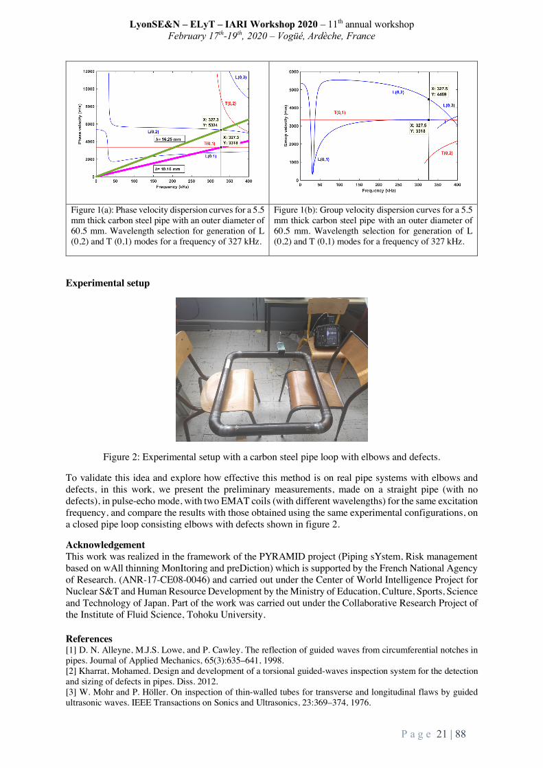
Figure 1(a): Phase velocity dispersion curves for a 5.5 mm thick carbon steel pipe with an outer diameter of 60.5 mm. Wavelength selection for generation of L (0,2) and T (0,1) modes for a frequency of 327 kHz.
Figure 1(b): Group velocity dispersion curves for a 5.5 mm thick carbon steel pipe with an outer diameter of 60.5 mm. Wavelength selection for generation of L (0,2) and T (0,1) modes for a frequency of 327 kHz.
Experimental setup
Figure 2: Experimental setup with a carbon steel pipe loop with elbows and defects.
To validate this idea and explore how effective this method is on real pipe systems with elbows and defects, in this work, we present the preliminary measurements, made on a straight pipe (with no defects), in pulse-echo mode, with two EMAT coils (with different wavelengths) for the same excitation frequency, and compare the results with those obtained using the same experimental configurations, on a closed pipe loop consisting elbows with defects shown in figure 2.
Acknowledgement This work was realized in the framework of the PYRAMID project (Piping sYstem, Risk management based on wAll thinning MonItoring and preDiction) which is supported by the French National Agency of Research. (ANR-17-CE08-0046) and carried out under the Center of World Intelligence Project for Nuclear S&T and Human Resource Development by the Ministry of Education, Culture, Sports, Science and Technology of Japan. Part of the work was carried out under the Collaborative Research Project of the Institute of Fluid Science, Tohoku University. References [1] D. N. Alleyne, M.J.S. Lowe, and P. Cawley. The reflection of guided waves from circumferential notches in pipes. Journal of Applied Mechanics, 65(3):635–641, 1998. [2] Kharrat, Mohamed. Design and development of a torsional guided-waves inspection system for the detection and sizing of defects in pipes. Diss. 2012. [3] W. Mohr and P. Höller. On inspection of thin-walled tubes for transverse and longitudinal flaws by guided ultrasonic waves. IEEE Transactions on Sonics and Ultrasonics, 23:369–374, 1976.

LyonSE&N – ELyT – IARI Workshop 2020 – 11th annual workshop February 17th-19th, 2020 – Vogüé, Ardèche, France
P a g e 22 | 88
8. Welding mechanism of friction stir-welding
ELyTGlobal
TransportationMaterialsandStructureDesign
Prof.YutakaS.SatoDepartmentofMaterialsProcessingTohokuUniversity6-6-02Aramaki-aza-Aoba,Aoba-kuSendai980-8579,Japan
Abstract 1. Introduction Friction stir welding (FSW) can make a high-quality weld in several structural materials, such as Al. Mg, Cu alloys and steels, using the solid-state stirring arising from rotation of an unconsumable welding tool [1,2]. FSW has been already used to produce many Al structures, such as rocket fuel tanks, aircrafts, rolling stocks, automobile, and so on. It is believed that FSW achieves full consolidation of the materials through the severe solid-state material movement, but it has been unclear how the full consolidation is achieved during FSW. Based on materials science, solid-state welding processes accomplish welding by bringing the atoms of the material to be welded to equilibrium spacing principally. However, real surface of the material is covered by the barrier layer mainly consisting of oxide layer and is too rough compared with the atomic scale, preventing the consolidation of the materials. To achieve the metallic bond between the materials in the solid state, therefore, two requirements should be met during welding processes, i.e., removal of the barrier (oxide) layer mainly, and contact between the materials in the atomic scale. In my presentation, welding mechanism of FSW attempts to be proposed with various experimental results based on the metallurgical point of view. 2. Fragmentation of oxide layer The zigzag line is often observed on the etched cross-section of the friction stir welds [3]. It is known that the zigzag line is the remnants of the oxide layer on the initial butt surfaces, because final position of the initial butt surface after material flow of FSW exhibits the zigzag line on the cross section [4]. To clarify the mature of the zigzag line, therefore, thin foil obtained from the zigzag line using focused ion beam (FIB) system was examined by TEM, showing that Al2O3 particles with an amorphous structure was locally distributed on the zigzag line [5,6]. This result suggests the oxide layer on the initial butt surface was well fragmented during FSW. 3. Material movement Severe material movement occurs around the welding tool during FSW. The material movement is hardly visible, but it could be deduced through the examination of crystallographic texture formation because the material movement is subject to the

LyonSE&N – ELyT – IARI Workshop 2020 – 11th annual workshop February 17th-19th, 2020 – Vogüé, Ardèche, France
P a g e 23 | 88
crystallographic nature of the deformation process. Therefore, our research team examined the crystallographic texture distribution in the stir zones of Al alloy 6063 and Mg alloy AZ61 by electron backscatter diffraction (EBSD) technique [7,8]. These studies clarified that the slip planes and directions were roughly parallel to the cylindrical probe surface and the rotating direction of the tool. This implies that FSW is achieved by simple shear stress arising from rotation of the welding tool along the probe column surface. 4. Welding mechanism Two requirements, removal of the barrier (oxide) layer and contact between the materials, are needed for the solid-state welding. TEM examination of the zigzag line revealed that fragmentation of the oxide layer was effectively achieved during FSW. The fragmentation of the oxide layer should result from the simple shear deformation during FSW because the simple shear deformation would break up the Al2O3 layer and create new oxide-free surface around the rotating probe. It should be noted that the material is entirely kept under the welding tool during normal FSW operation. However, the tool probe is plunged into the material to be welded during FSW, so that the material having the same volume as the probe should be squeezed out from the material in order to keep the material volume constant. The detailed phenomena are still unclear, but the pressure inside the stir zone should be high, resulting in the metallic bond through effective contact between the oxide-free surface produced by simple shear deformation in the atomic scale. This would be a solid-state welding mechanism of FSW. This study proposes that a possible mechanism of FSW consists of fragmentation of the oxide layer by simple shear deformation, and atomic-scale contact between the oxide-free surfaces under the welding tool [9]. References:
[1] R.S. Mishra and M.W. Mahoney: Friction Stir Welding and Processing, ASM International, Materials Park, OH, (2007).
[2] R. Nandan, T. DebRoy, and H.K.D.H. Bhadeshia, Progress Mater. Sci. 53 (2008) 980–1023. [3] H. Okamura, K. Aota, M. Sakamoto, M. Ezumi, and K. Ikeuchi, Quart. J. Jpn. Weld. Soc. 19 (2001) 446–
456. [4] A.P. Reynolds, Sci. Technol. Weld. Joining 5 (2000) 120–124. [5] Y.S. Sato, F. Yamashita, Y. Sugiura, S.H.C. Park, and H. Kokawa, Scripta Mater. 50 (2004) 365–369. [6] Y.S. Sato, H. Takauchi, S.H.C. Park, and H. Kokawa, Mater. Sci. Eng. A 405 (2005) 333-338. [7] Y.S. Sato, H. Kokawa, K. Ikeda, M. Enomoto, S. Jogan, and T. Hashimoto, Metall. Mater. Trans. A 32A
(2001) 941–948. [8] S.H.C. Park, Y.S. Sato, and H. Kokawa, Metall. Mater. Trans. A 34A (2003) 987–994. [9] Y.S. Sato: Materia Japan, 55-2 (2016) 53-58.

LyonSE&N – ELyT – IARI Workshop 2020 – 11th annual workshop February 17th-19th, 2020 – Vogüé, Ardèche, France
P a g e 24 | 88
9. Advancement of acoustic emission inspection using system invariant analysis technology
ELyTGlobal
ProjectNEC&IFSJointresearch
ToshiyukiTAKAGIInstituteofFluidScience,[email protected]
TetsuyaUCHIMOTOInstituteofFluidScience,[email protected]
Abstract:
1. Introduction
The acoustic emission (AE) test is used as a method of non-destructive inspection in industry. In this technique, a crack occurs in a structural material such as a pipe, and when a crack propagates in the structure, it receives a signal of an elastic wave generated by energy released to judge the presence or absence of abnormality. Therefore, it can be collected by a sensor fixed to the surface of the structure. However, in an actual examination, it is very difficult to capture a target abnormality with many environmental noises.In recent years, AI technology and big data analysis method are rapidly growing. It is also beginning to be used in the field of non-destructive inspection. System invariant analysis technology (SIAT) can process various data sets to discover hidden patterns, unknown relationships and other useful information [1]. When such technology is used for AE inspection, various effects including improvement of inspection accuracy can be expected.The purpose of this research is to apply the SIAT method to evaluate the feasibility of SIAT as a tool for processing AE data of fatigue test and monitoring the health of structures. For that purpose, we collect the AE signal in the fatigue test of aluminum alloy and evaluate the result processed by SIAT.
2. What is System Invariant Analysis Technology (SIAT)
Invariant analytical technology is a machine learning technique that comprehensively extracts relationships between time series of numerical values obtained as system performance information and plant sensor information 1). By using the relationship between the learned sensor information as an operation model of the target system and monitoring the time and place where the relationship changed at real time, it is possible to detect abnormal symptoms at an early stage (Fig.1)

LyonSE&N – ELyT – IARI Workshop 2020 – 11th annual workshop February 17th-19th, 2020 – Vogüé, Ardèche, France
P a g e 25 | 88
Fig. 1. System Invariant Analysis Technology(SIAT) Overview
In anomaly detection, the value of the corresponding sensor (y term) is predicted by substituting the current process value into the x term of the model expression of invariant learned and extracted automatically. When this predicted value and current value deviate from the "usual range" learned at the time of model creation, detection is made as abnormality.
2. Application to AE inspection
In order to verify the applicability of the SIAT system, test data of crack specimens and crackless specimens were obtained respectively. Figure.2 is an abnormal score obtained as a result of processing the AE signal measured during the fatigue test of the intact test piece by SIAT. Overall, it can be seen that the value of the abnormal score stably fluctuates in the range of 100 to 300.
Next, the abnormality score calculated by SIAT is shown in Fig. 4 using the data during the fatigue test of the crack specimen. The abnormal score at the initial stage is low.Over time, abnormal scores show an upward trend, the maximum value exceeds 800. It decreased suddenly after reaching the peak in about 30 minutes. Subsequently, the value of the abnormal score falls to a much lower initial stage. This is due to the broken specimen.
Figure.2Anomalyscoreofintactspecimen Figure.3Anomalyscoreofintactspecimen
Inthisway,itwaspossibletomaketheAEsignaldifficulttorecognizewithhumaneyesbyprocessingwithSIATtomakeiteasytosee.Thisseemstoindicatethatevenasmallinexperiencedexaminercandoacertaindegreeofexamination.
References:
[1] Guofei Jiang, Haifeng Chen, Kenji Yoshihira, Discovering likely invariants ofdistributedtransactionsystemsforautonomicsystemmanagement,ClusterComput.(2006)9:385–399DOI10.1007/s10586-006-0008-1

LyonSE&N – ELyT – IARI Workshop 2020 – 11th annual workshop February 17th-19th, 2020 – Vogüé, Ardèche, France
P a g e 26 | 88
10. Interaction between Rubber and Ice Studied Using Low-Temperature Surface Forces Apparatus
ELyTGlobalELiceTrib7
Transportation
Surface Interface
Prof.KazueKuriharaNICHe,TohokuUniversity,[email protected]
Dr.MotohiroKasuyaIMRAM,TohokuUniversity
Prof.DenisMazuyerSTMS/LTDS,ECL
Dr.JulietteCayer-
BarriozCNRSResearchDirector
STMS/LTDS,ECL
Abstract Thedrivingoniceisadelicateexerciseduetothepooradherenceperformanceoftireoniceandtheprohibitionofstuddedtiresinmanycountries.Inacontextofroadsafetyimprovementundersevereclimaticconditions,itisnecessarytopreciselystudytheslidingcontactbetweenrubberandiceanddeterminethedifferentkeymechanismswhichleadthetribologicalbehavioroftherubber-icecontact. Westudiedtherubber-icecontactemployingthesurfaceforcesmeaurementwhichcouldlink the phenomena ofmacroscale to those of nanoscale. A low temperature surface forcesappratus (SFA) was developed for this study. This apparatus was used to examine theinteractionsbetweeniceandsilicasurfaces(bynormalforcemeasurement)andthepremeltinglayeroftheicesurface(byresonanceshearmeasurement(RSM)). We also performed RSM based on the low-temperature SFA to evaluate the viscoelastic properties of the interfaces between rubber and ice. This method was applied to three kinds of rubbers used for the tire tread, which exhibited different viscoelasticities. The influence of the multiple asperity contact was observed at a lower applied load (L < 10 mN). The viscoelastic properties of the interface at a higher L were not influnced by the multiple asperity, and could be incompared with those of the bulk rubbers. References 1) Low-Temperature SurfaceForcesApparatus toDetermine the Interactionsbetween Ice
and Silica Surfaces, F. Lecadre,M. Kasuya,A. Harano,Y. Kanno and K. Kurihara,Langmuir,34(38),11311-11315(2018)
2) Viscoelasticity of Rubber–Ice Interfaces Under Shear Studied Using Low-TemperatureSurface Forces Apparatus, S. Hemmette,M.Kasuya, F. Lecadre, Y. Kanno, D.Mazuyer, J.Cayer-Barrioz,K.Kurihara,Tribo.Lett.,67:74(2019)
3) Ice Premelting Layer Studied by Resonance ShearMeasurement (RSM), F. Lecadre,M.Kasuya,Y.Kanno,K.Kurihara,Langmuir,35(48),15729-15733(2019).
7Tribologyofelastomer/icecontactfromnmtommscale

LyonSE&N – ELyT – IARI Workshop 2020 – 11th annual workshop February 17th-19th, 2020 – Vogüé, Ardèche, France
P a g e 27 | 88
11. Reduced oxygen availability triggers aerotactic migration of Dictyostelium
ELyTGlobalMicroCell8
Theme: Engineering for Health
Scientific topic: Microsystems for Cell Engineering
Prof.Jean-PaulRIEU
(iLM,UCBL)
Assoc.Prof.KenichiFUNAMOTO(IFS,TohokuUniversity)
Cochet-EscartinO.,AnjardC.,andRieuJ.P.(InstituteofLightandMatter,UniversityClaudeBernardLyon1andCNRS,Villeurbanne,France)HiroseS.,andFunamotoK.(InstituteofFluidScience,TohokuUniversity,Sendai,Japan)
Abstract It has been known for the last three decades that cells are able to detect and adapt to various concentrations of oxygen (O2) as just highlighted by the Nobel Prize in Medicine 2019 [1]. In a situation of hypoxia (low O2), the HIF (Hypoxia-Inducible Factor) complex associates with DNA to regulate the expression of certain adaptation genes, while in presence of O2 (normoxia) HIF is inactivated. It has also long been known that bacteria, rather than regulating genes for adaptation, move toward O2, a mechanism called aerotaxis [2]. Recently, it was demonstrated that epithelial cells also exhibit directed migration toward oxygen using a very simple spot assay: after covering an epithelial cell monolayer by a coverglass non permeable to O2, peripheral cells exhibited a strong outward directional migration to escape hypoxia from the center of the colony [3]. Following that assay, we showed at iLM that the social amoeba Dictyostelium (Dicty) also displayed a spectacular phenotype when the cells consumed the surrounding O2 (Fig. 1 left): most cells moved quickly outward of the hypoxia area, forming a dense expending ring moving at constant speed. Hence, aerotaxis seems a conserved mechanism in various eukaryotic cells. The collective response induced by self-generated hypoxia observed in our spot assay can be described by a few readouts on the ring: formation time, speed, and shape. It was modeled using a combined agent based with diffusion model (CompuCell3D). However, the molecular nature of this O2
directed migration remains elusive as well as the detection and sensing mechanisms (sensitivity to a threshold or to a gradient, response time, and cell adaptation). To get insight in the sensing mechanisms, we aim to develop oxygen gradient microfluidic devices to investigate the cell response to various types of O2 gradients as functions of gradient steepness and absolute O2 level. Original device design was adapted from Funamoto’s existing devices for observations of cancer and endothelial cells [4]. An effort was made to reach very low O2 levels (<1% O2) and a fast response, with gas channels positioned just above the media channel with cells (Fig. 1 right). O2 sensing films based on the fluorescence quenching by O2 were included under the media channel. The device was fabricated in NanoLyon facility during
8MicrosystemsforCellEngineering

LyonSE&N – ELyT – IARI Workshop 2020 – 11th annual workshop February 17th-19th, 2020 – Vogüé, Ardèche, France
P a g e 28 | 88
a two-month stay of Funamoto and Hirose at iLM in 2019. It was successfully tested with Dicty. We found that an O2 gradient can be established within 15 min and that cells exhibit directional migration toward O2 in the case that the O2 level is <2% O2.
The main objectives of this project are to screen an available Dicty mutant collection, especially the mutants associated with proteins involved in the HIF pathway, and to understand O2-driven cell motility at molecular, cellular and multicellular level, using our simple spot assay and microsystems.
Figure 1. Left) A spot of initially densely packed Dictyostelium cells (20 min) quickly moveoutwardwith the formation of a ring of cells when covered by a coverglass (3 h). Each spotcontains2000cellsatthebeginningoftheassay.Right)Fromtoptobottom:devicegeometrywithtwogaschannelaboveamediachannelwhosebottomiscoveredwithanoxygensensingfilm;rawfluorescencesignal(thebrighterthefluorescenceintensity,thelowertheoxygenconcentration);calculatedoxygenmapandprofilealongmediachannel.
References:
[1] Press release: The Nobel Prize in Physiology or Medicine 2019. https://www.nobelprize.org/prizes/medicine/2019/press-release/ NobelPrize.org. Tue. 8 Oct 2019. [2] M. Alder, et al. Studies of bacterial aerotaxis in a microfluidic device. Lab Chip, 12(22) (2012) 4835–4847. [3] M. Deygas, et al. Redox regulation of EGFR steers migration of hypoxic mammary cells towards oxygen. Nat. Comm. 9 (2018) 4545. [4] K. Funamoto, et al., Lab Chip, 12 (2012), 4855–4863.; K. Funamoto, et al., Integr. Biol., 9 (2017), 529–538.

LyonSE&N – ELyT – IARI Workshop 2020 – 11th annual workshop February 17th-19th, 2020 – Vogüé, Ardèche, France
P a g e 29 | 88
12. Tspan8 and EMT-TFs in melanoma progression
IARI
Theme: Malignant melanoma Scientific topic: Molecular actors of melanoma progression
Dr.IngridMASSE
Abstract Melanoma is the deadliest skin cancer due to its high proclivity to metastasize. The targeted- and immune-therapies recently developed have not yielded the expected results, since almost all patients relapse. Therefore, understanding the molecular mechanisms of early melanoma cell invasion is crucial to improve patient survival. We previously demonstrated that Tetraspanin8 (Tspan8), a transmembrane protein known as an inducer of metastases in numerous carcinomas, is not expressed in normal skin and benign lesions, and that its expression arises with the progression of human melanoma. We also showed that Tspan8 plays a major role in the transition of melanoma cells towards an invasive phenotype, and could be a predictive factor of poor prognosis in melanoma patients. At the molecular level, we deciphered the transcriptional regulators of Tspan8 and identified LCMR1, p53 and β-catenin as significant actors implicated in Tspan8 regulation for acquisition of melanoma invasive properties. We are currently beginning to investigate the role of Tspan8 and its transcriptional regulators in the Medaka fish, a model of spontaneous melanoma development presenting strong molecular and phenotypic similarities with human melanoma.

LyonSE&N – ELyT – IARI Workshop 2020 – 11th annual workshop February 17th-19th, 2020 – Vogüé, Ardèche, France
P a g e 30 | 88
13. Specific Recruitment of Brain Immune Cell of Microglia Following Brain Injury Utilizing Embryonic Medaka Model
IARI
Health: Neuroprotective mechanism Dynamics of activated microglia in response to radiation-induced brain injury
TakakoYasudaAffiliation:DepartmentofIntegratedBiosciences,GraduatedSchoolofFrontierSciences,TheUniversityofTokyo,Japan
Abstract Microglia are the resident immune cells in the central nervous system (CNS) of vertebrates. When
brain is injured, microglia migrate toward dying neurons and remove apoptotic cells by phagocytosis. While their primary role is the clearance of apoptotic cell debris, microglia play the Janus-faced roles in the damaged CNS. Activated microglia also release cytokines and cause prolonged inflammation in the CNS, which can affect CNS functions. Cranial radiation therapy (CRT) is a widely accepted treatment for intracranial tumors because it is non-invasive compared with surgical resection. However, CRT has a significant risk to induce detrimental effects such as cognitive impairment which might be caused by excessive activation of microglia following irradiation. To minimize the adverse effects on normal tissue surrounding the tumor during CRT, understanding and regulation of the microglial dynamics in the irradiated CNS would be highly advantageous; however, these issues have not yet to be fully addressed.
Japanese medaka fish, Oryzias latipes, have an advantage over the mouse model: their embryos are small size and highly transparent, that enable us to observe the detailed process of induction of neuronal death and their removal by microglia in irradiated brains. We have demonstrated that the microglial activation includes two steps throughout the phagocytotic process, which can be indicated by the specific two biomarkers; L-plastin (lymphocyte cytosolic protein 1) at the initial phase of irradiation-induced phagocytosis and Apolipoprotein E (ApoE) at the later phase, respectively. Furthermore, we established experimental procedures for targeting irradiation in the optic tectum (OT) of medaka embryonic brain by a collimated carbon-ion system at the facility of Takasaki Ion Accelerators for Advanced Radiation Application (TIARA) in National Institutes of Quantum Beam Science and Technology (QST). Contrary to our expectations, activated microglia were present outside the irradiated region of the OT during the later phase of phagocytosis, even though apoptotic neurons were only induced in the locally irradiated region of the OT. These findings suggest the possibility that the abscopal activation of brain immune system might be major cause for excessive activation of microglia after CRT in human patient that would induce adverse effects following CRT. The medaka embryonic brain is a promising model system to investigate the dynamics of activated microglia in response to brain injury by irradiation.
Now, I have been investigating the most effective time window to administrate the inhibitor to suppress the unnecessary activation of microglia, that would make a proposal of new therapeutic strategy for radiotherapy to regulate microglial activation.

LyonSE&N – ELyT – IARI Workshop 2020 – 11th annual workshop February 17th-19th, 2020 – Vogüé, Ardèche, France
P a g e 31 | 88
14. EMT regulates DNA repair pathways controlling genome instability
IARI
Theme: Cancer treatment Scientific topic: ZEB1 vs Theta-mediated End-Joining
DrAgnèsTISSIER
Abstract Genomic instability is commonly accepted as a hallmark of cancer. A prominent contributor to CIN during tumorigenesis is the mutagenic repair of double-strand breaks (DSB) eventually resulting from an oncogenic activation. Mammalian cells rely on two major pathways for DSB repair: canonical non-homologous end-joining (c-NHEJ) and homologous recombination (HR). Additionally, a third highly mutagenic end-joining pathway, mediated by the DNA polymerase theta (POLθ, encoded by the POLQ gene), named Theta-mediated end-joining (TMEJ). To address the central question of TMEJ regulation, we tested whether the gene expression of the TMEJ actors differs in primary breast tumors depending on CIN. In silico and then in vitro experiments led us to the observation that the expression of the POLQ gene was lower, as well as the POLθ protein level in low instability primary tumors and cancer cell lines compare to high instability ones. The zinc finger E-box binding homeobox 1 (ZEB1), an epithelial to mesenchymal transition (EMT) regulator, was characterized in our team by a specific high expression in low CIN tumors and has been shown to confer a chemotherapeutic resistance to breast cancer. We demonstrated that POLQ and ZEB1 expression were mutually exclusive in primary tumors. Furthermore, we established that the POLQ gene was a direct transcriptional target of ZEB1 and that modulation of POLQ expression resulted in a reduction of TMEJ activity, suggesting a previously unrecognized role of ZEB1 as a repressor of TMEJ. Finally, a depletion of ZEB1 allowed the sensitization of ZEB1-expressing cells to different cancer drugs in a POLθ-dependent mechanism. In conclusion, our findings identified ZEB1 as a pivotal factor required for orchestrating DSB repair pathway choice and as a consequence may act for a predictive therapeutic indicator.

LyonSE&N – ELyT – IARI Workshop 2020 – 11th annual workshop February 17th-19th, 2020 – Vogüé, Ardèche, France
P a g e 32 | 88
15. Anaphase Promoting Complex key subunits identified as prognostic factors in colorectal and breast cancers
IARI
Theme: Cell cycle and cancer Scientific topic: Anaphase Promoting Complex and tumor progression
Prof.CarolineMoyret-Lalle
Abstract Precise control of the cell cycle phases is essential to maintain genetic stability. Perturbation of cell cycle progression may compromise the transmission of genetic information, leading to DNA damage, mutations, and chromosomal instability (CIN). CIN is an intricate phenomenon that is often found in many types of human cancers, characterized by persisting errors in chromosome segregation. This ongoing chromosome mis-segregation results in structural and numerical chromosomal abnormalities that have been widely described to promote tumor evolution. In breast cancer, CIN is commonly part of the genomic landscape of the disease and has a higher incidence in aggressive sub-types. In colorectal cancers, chromosomal instabilitycarcinogenesis pathway account for ~85% of the tumors. We have studied the involvement of the anaphase-promoting complex APC/C, a specific ubiquitin ligase complex central to chromosome segregation, in colorectal and breast cancer progression. In colorectal cancer, we uncovered a novel and likely predictive marker, APC11, the key enzymatic subunit of the APC/C, using an innovative integrated analysis incorporating relevant protein markers and clinical variables. Through multivariable regression models and multiple correspondence analysis (MCA), we found that APC11 protein expression appeared to be independent of the other known protein markers studied, and thereby might be a new independent predictive marker. In breast cancer, survival analyses showed that another APC/C subunit, APC7, involved in substrate recognition of the enzymatic complex, is associated with worse prognosis. In Conclusion, our results showed an association between expressions of key APC/C subunits and poor tumor prognosis.

LyonSE&N – ELyT – IARI Workshop 2020 – 11th annual workshop February 17th-19th, 2020 – Vogüé, Ardèche, France
P a g e 33 | 88
16. Experimental flow investigations for medical device improvement and safety evaluation
ELyTGlobal
Health, Imaging processing
Dr.SimonTUPIN
InstituteofFluidScience,TohokuUniversity
Pr.HidekiOTA
TohokuUniversityGraduateSchoolofMedicine
Mr.MakotoITO
GraduateSchoolofMechanicalEngineering,TohokuUniversity
Pr.KeiTAKASE
TohokuUniversityGraduateSchoolofMedicine
Pr.MakotoOHTA
InstituteofFluidScience,Tohoku
University
Abstract The purpose of this presentation is to introduce recent works related to biomedical flow dynamics. The authors are open to new collaborations within ELyT Global. Study 1: Quantitative assessment of aortic tree flow and geometry The aorta is the biggest artery of the human body, distributing blood from the heart to all organs thanks to a branching geometry. Although patient specific assessment of diseased aortic geometry and flow are commonly reported, healthy volunteer data are not easily accessible to the biomedical engineering community. Such data would greatly help researchers to better understand and simulate the complex physiological conditions of this vessel. By means of non-invasive imaging (MRI), quantitative aortic tree geometry and flow data (fig.1a) were recorded and processed in an engineering point of view to provide useful information for the improvement of blood flow dynamic studies.

LyonSE&N – ELyT – IARI Workshop 2020 – 11th annual workshop February 17th-19th, 2020 – Vogüé, Ardèche, France
P a g e 34 | 88
Study 2: Braided stent for aortic aneurysm Abdominal aortic aneurysm (AAA) is the most common type of aneurysm. In such case, the aneurysm is located close to the aorta-renal artery bifurcations, which are usually covered by stent graft during treatments, raising safety concerns related to renal functions deteriorations. Cardiatis company (Isnes, Belgium) developed the Multilayer Flow Modulator (MFM), a braided stent design (i.e., porous), which may solve this issue. The purpose of this study was to experimentally evaluate hemodynamics changes following the deployment of such device in an AAA model. Particle image velocimetry (PIV) experiments revealed significant blood flow velocity reduction in the aneurysm and branch flow rate preservation after deployment a MFM. Micro-computed tomography (micro-CT) imaging revealed a highly porous microstructure. CFD simulations were finally performed to estimate the permeability of the braid geometry imaged by micro-CT. Study 3: Cancellous bone permeability Bone marrow is the most frequently used source of stem cells, which represent a potential treatment for various diseases. Those cells are extracting from bone by harvesting during an operation called bone marrow aspiration, invasive process causing pain, anxiety and depression. Optimizing the aspiration process could lead to quicker operation and pain reduction. The objective of this study was to characterize the relationship between permeability and microstructure parameters of iliac cancellous bone. Combining micro-CT imaging (fig.1c), flow experiment and pore network modelling, the relationship between bone microstructure and its permeability was clarified. Results revealed an anisotropic behavior of the flow permeability. Its location and directional dependency were correlated with porosity and tortuosity, respectively. Such analysis of cancellous bone microstructure can help the optimization of needle design and puncture location in order to better harvest stem cells.
Figure 1: (a) Flow rate curves estimated from the phase-contrast MR images in different sections along the aorta, (b) deployment of an endovascular in an AAA model and (c) cross
section of a porcine iliac cancellous bone imaged by micro-CT. Acknowledgements This work was supported by JSPS KAKENHI [grant number 18K18356] and ImPACT program of Council for Science, Technology and Innovation (Cabinet Office, Government of Japan). The authors would like to thank Pr. Harumasa Kano (Tohoku University Museum) and Mr. Tomoyoshi Kimura (Tohoku University Hospital) for their help with micro-CT and MR imaging process, respectively.
LyonSE&N – ELyT – IARI Workshop 2020 – 11th annual workshop February 17th-19th, 2020 – Vogüé, Ardèche, France
P a g e 35 | 88
17. Telomere as the starting point of anticancer drug discovery
IARI
Health: Cancer drug discovery Scientific topic: Tankyrase, G-quadruplex
Dr.HiroyukiSEIMIYA
Abstract Telomeres protect the chromosomes ends from DNA damage response. In human somatic cells, telomeres gradually shorten at each cell cycle and eventually induce senescence or cell death. On the contrary, most cancer cells reactivate the telomere-synthesizing enzyme, telomerase, and exhibit an immortalized phenotype. Tankyrase poly(ADP-ribose) polymerase promotes the telomerase-mediated telomere elongation in human cells. We previously demonstrated that double blockade of telomerase and tankyrase causes efficient telomere shortening and crisis of cancer cells. Because tankyrase also enhances Wnt/β-catenin signaling, it has been postulated as a therapeutic target of Wnt-driven cancer. We developed highly selective tankyrase inhibitors that block colorectal cancer cell growth in vivo. We also found that colorectal cancer cells with shortly truncated APC mutations and the cancer stem-like cell subpopulations are sensitive to tankyrase inhibitors. Meanwhile, telomeric nucleic acids form higher-order structures called G-quadruplexes (G4s). G4s exist not only at the telomeres but also at transcriptionally active sites. We developed G4 ligands, small compounds that stabilize G4. These ligands induce DNA damage response and preferentially target glioma stem cells. We also found that G4 ligands inhibit transcription and translation of mRNAs that contain G4-forming sequences. In conclusion, our drug discovery seeds, tankyrase inhibitors and G4 ligands, both derived from telomere biology, will provide opportunities for innovative anticancer drug development.

LyonSE&N – ELyT – IARI Workshop 2020 – 11th annual workshop February 17th-19th, 2020 – Vogüé, Ardèche, France
P a g e 36 | 88
18. Tribological characterization of acrylic composite materials for bone biomodel: the effects of alumina cement on drilling
haptics
ELyTGlobalBoneDrill9
Health
Materials&StructureDesign
YutaMURAMOTOGraduateSchoolofBiomedicalEngineering,TohokuUniversity/LTDS,ECL
VincentFRIDRICILTDS,EcoleCentraledeLyon
PhilippeKAPSA,LTDS,EcoleCentraledeLyon
GaëtanBOUVARD,LTDS,EcoleCentraledeLyon
MakotoOHTAELyTMaXUMI3757,CNRS–UniversitédeLyon–TohokuUniversity,InternationalJointUnit,TohokuUniversity
Abstract 1. Introduction
Drilling of bone is the fundamental surgical skill in the specialties such as orthopedics, dentistry, and neurosurgery. Errors in drilling carry several risks causing medical accidents including implant failures or bone refractures. Therefore, surgeons are requested to master drilling skills and likewise developers of medical devices provide performant products. Since the number of operation is continuously increasing [1], the society has to respond to this trend immediately, by improving accessories involving surgical education or mechanical tests toward development of medical devices.
The authors believe that bone biomodel can contribute to the more efficient surgical training and mechanical tests compared to natural bone whose usage has such drawbacks as risk of infections, limited accessibility, and biological deterioration, in addition to the less and less social tolerance. However, bone biomodels currently available in the market exhibit clinically relevant results only under limited circumstances [2]. Moreover, drilling of bone biomodels has seldom been in the research scopes and thus quite few literatures can be found on drilling haptics of materials for bone biomodels. Then, this study focuses on acrylic composite materials including alumina cement, and drilling was characterized to compare their drilling haptics with those of bone as obtained in the previous report [3].
2. Materials and methods
2.1. Sample preparation Acrylic composite materials were fabricated by quick polymerization method using acrylic resin as a
matrix and ceramic additives. Alumina cement was put together during the mixing process of polymer powder and monomer liquid of acrylic resin. The mixing ratio of the polymer and the monomer was constant at 1:1 of weight percentage. In the completion of polymerization after more than 24 hours, the mixture was taken out of the container as a solid block. Acrylic blocks were then processed to have a flat surface ready for drilling tests. The pure acrylic specimen was notated as PMMA, acrylic composite materials as AC20 and AC40, depending on the weight ratio of alumina cement.
9DevelopmentandFrictionCharacterizationofBiomodelsofBones

LyonSE&N – ELyT – IARI Workshop 2020 – 11th annual workshop February 17th-19th, 2020 – Vogüé, Ardèche, France
P a g e 37 | 88
Controls included natural bones and bone substitutes referred from the previous study [3]: canine and porcine mandible bones, and Sawbones models called Saw-PU20, Saw-PU50 for rigid polyurethane foam with their density of 0.32 and 0.80 g/cm3, and Saw-EP for glass fiber-reinforced epoxy resin.
2.2. Drilling tests Drilling tests were performed on a device developed by LTDS, based on a spindle Electrobroche SD
5084, Precise. The device included a system for application of thrust force, a strain gauge for measurement of torque, and a displacement sensor. Each work piece was fixed on the work table using double-faced adhesive tape. A twist drill (Nobel Biocare Japan Co., Ltd) of a diameter of 2.0 mm was used. Surgical machining conditions were selected such as 1,000 rpm of spindle speed, 20 N of thrust force, and 5 mm of maximum displacement. Drilling torque and displacement were recorded with a sampling rate of 200 Hz. Acquired results were smoothed. The maximum value of torque and the drilling time before reaching 5 mm were extracted and averaged. Measurements were performed for 3 times, at room temperature under dry conditions without irrigation.
2.3. Microindentation tests Indentation tests were performed on the universal nanomechanical tester (ZwickRoell) with a diamond
pyramid indenter, Berkovich type, of a face angle of 115.12°. Each sample was embedded in epoxy resin and polished using emery paper of P800, 1200, 2400, and 4000, and then with diamond slurry of a diameter of 1.0 µm. The indenter was loaded until 500 mN at the strain rate of 3.0×10⁻² s-1. Five times of measurements were conducted. Local deformation was generated by the quasi-continuous stiffness measurements (QCSM) technique. The effects of additives on mechanical properties such as hardness and elasticity, and also on the drilling time obtained from drilling tests were observed.
3. Results and discussion
Fig. 1 shows the relationship between maximum torque and drilling time among tested specimens. It was confirmed that the drilling time for the composite materials tend to increase with additive amount, and this effect becomes larger along the increase in additive amount up to 40 wt%. It was hypothesized that the higher the additive amount is, the less the materials can be removed by cutting tool, resulting in lower torque and longer drilling time. Thus, mechanical properties possibly altered due to additives.
Microindentation tests indicated that both hardness and elasticity increase along the additive amount. Fig. 2 shows the relationship between hardness and the drilling time. It was proposed that the drilling time is equivalent among AC40 and bones regardless of their hardness. This trend was similar for elasticity also obtained in the microindentation tests. Therefore, it is considered that the equivalence of hardness or elasticity may have less impacts on the resemblance of drilling haptics.
Fig. 1: Relationship between maximum torque and drilling
time indicating the effects of additive inclusion Fig. 2: Relationship between hardness and drilling haptics
Acknowledgement The authors wish to thank Prof. Viguier from VetAgro Sup, University of Lyon, for kindly offering
bone specimens. This work was supported by the JSPS Core-to-Core Program, the Program for Leading Graduate Schools, IFS collaborative research project, and the LABEX MANUTECH-SISE (ANR-10-LABX-0075) of University of Lyon, within the Program "Investissements d'Avenir" (ANR-11-IDEX-0007) operated by the French National Research Agency. LIA ELyT Global is also acknowledged.References [1] The Japanese Society of Arthroplasty Replacement, Annual Report 2017, (2017). [2] J.-T. Hausmann, Osteo and Trauma Care, 14(2006) 259–264. [3] Y. Muramoto et al., ELyT Workshop 2019, Naruko Kanko Hotel, Osaki, Japan.
LyonSE&N – ELyT – IARI Workshop 2020 – 11th annual workshop February 17th-19th, 2020 – Vogüé, Ardèche, France
P a g e 38 | 88
19. Optimizing surface finish to Prevent SCC initiation in the energy industries
ELyTGlobalOPSCC10
Energy, Materials & Structure design
Surfaces & Interfaces
H.Abe1N.Mary1,2T.Miyazaki1Y.Watanabe1,21:TohokuUniversity2:ELyTMaX
B.Ter-Ovanessian1,B.Normand1,K.Jaffre1,21:MATEISINSALyon2:ElyTMaX
Abstract 1. Introduction The selection of structural materials for applications is usually done from their mechanical properties and adding a safety coefficient to take into account some environmental effects. If this methodology can be used in most applications, additional precautions are required in energy industries. Synergistic effects can be activated between the material metallurgy, the environment, and mechanical stresses when the material is exposed under extremes conditions (pressure, temperature, strongly aggressive solution, etc.). In various kinds of environments, including boiling water reactor coolant, primary circuit of pressurized water reactor and chloride containing water, the material surface state is the key parameter to control the corrosion and Stress Corrosion Cracking (SCC) susceptibility of alloys. For example, it has been widely accepted that surface machining enhances SCC susceptibility of non-sensitized austenitic stainless steels in a boiling water reactor environment. Surface finishing operations such as grinding, wire brushing, machining produce surface states that compromise the corrosion resistance of oxidative and passive materials [1]. These processes affect the electrochemical and mechanical stabilities of the material at the microstructure scale and also the passive film properties [2]. A part of our collaborative study (Project ELyT lab: R32 – Understanding and managing stress corrosion cracking) showed that even slight cold work introduced with fine emery finish has a significant impact on oxidation features [3] and cracking susceptibility of Ni-base alloys in superheated steam. Until now, researches focused on the relation between the microstructural modification induced by the surface preparation on the SCC behavior of material or the selection of the most suitable treatment [4,5]. However, industries need a guideline for surface finish procedures to reasonably minimize SCC susceptibility of components. To achieve an effective answer to this demand, new knowledge is required on: - Physical metallurgy of alloy subsurface (micro- and nano-structure of the surface) - Electrochemical properties, in particular, the stability of passivity (re-passivation kinetic, growth
mechanism) - SCC initiation dynamic (embryo formation, re-passivation, the coalescence of micro-cracks). All those properties need to be linked each other to understand the effect of surface finish on SCC susceptibility of alloys.
10OptimizingsurfacefinishtoPreventSCCinitiationinenergyindustries

LyonSE&N – ELyT – IARI Workshop 2020 – 11th annual workshop February 17th-19th, 2020 – Vogüé, Ardèche, France
P a g e 39 | 88
Figure 1: Frame of the project
2. First results
To highlight the influence of surface finishing process used in maintenance, the corrosion and SCC behavior of ground and mechanically polished samples (2400-SiC, diamond paste 1µm, and colloidal silica polishing) have been studied for three grades of stainless steel (304L, 316L, 316NG). Firstly, the features of microstructural modification at the subsurface have been acutely characterized with SEM, FIB and TEM observations. The ground samples exhibit a larger subsurface recrystallization zone (in addition to a deformed layer and a hardened one) than the mechanically polished samples. Then, this study has been focused on the understanding of the influence of such different surface states on the corrosion behavior and localized corrosion susceptibility of the different stainless steels. To characterize the passive film, electrochemical impedance spectroscopy measurements coupled with the Mott-Schottky approach were carried out following a methodology developed in the MATEIS laboratory based on the analysis of impedance diagrams. These analysis techniques make it possible to determine the type of semi-conductivity (type-n, type-p), the main charge carriers nature and their density as well as the thickness of the film. Measurements with the XPS technique were also carried out to correlate results from the electrochemical tests to the chemistry and nature of the passive films. Passive film resistance to pitting corrosion was also studied by performing potentiodynamic experiments in chloride-containing solutions. Relationship between the electrochemical results, the stability and the resistance of the passive film can be drawn regarding the microstructural modifications related to surface treatments. As a first conclusion, surface finishing doesn’t play a significant role in the composition, the semiconductive behavior of the passive films in a non-aggressive environment (borate buffered solution). Indeed, even if the doping density or the passive film thickness are affected by the subsurface microstructure, the passive behavior of the stainless steel remains almost identical. However, in the presence of chloride ions, ground samples mainly lose their passive behavior (high current density) while the other samples exhibit a passive plateau and a passivity breakdown. Hence, increased roughness, amount of topological defects and subsurface compressive stresses induce an increased susceptibility to passive film/chloride interactions.
3. Prospects Next steps of this study are related to the oxidation behavior of the same materials and surface states in two environments more representative of nuclear plant: simulated BWR water environment (288 oC, 9 MPa, DO: 8 ppm) and simulated PWR primary water environment (325 oC, 15 MPa, B: 500 ppm, Li: 2.0 ppm, DH: 30 cc/kg). Characterization of the oxide scale will be performed by different techniques: SEM, FIB and TEM, XPS or SIMS. Moreover, the semiconductive behavior of these oxides will be determined by a similar Mott-Schottky approach. In this case (thick and complex oxide films), challenging concerns remains on the definition or the optimization of the protocol to obtain robust and accurate electrochemical data. And finally, the resistance of these thermally grown oxides to pitting corrosion will be also investigated.
QSE, Tohoku UniversityMATEIS, INSA-Lyon

LyonSE&N – ELyT – IARI Workshop 2020 – 11th annual workshop February 17th-19th, 2020 – Vogüé, Ardèche, France
P a g e 40 | 88
References :
[1] M. Moine, N. Mary, B. Normand, L. Peguet, A. Gaugain, H.N. Evin, Tribo electrochemical behavior of ferrite and ferrite–martensite stainless steels in chloride and sulfate media, Wear. 292–293 (2012) 41–48. DOI:10.1016/j.wear.2012.06.001.
[2] B. Ter-Ovanessian, N. Mary, B. Normand, Passivity Breakdown of Ni-Cr Alloys: From Anions Interactions to Stable Pits Growth, J. Electrochem. Soc. 163 (2016) C410–C419. DOI:10.1149/2.0381608jes.
[3] F. Hamdani, H. Abe, B. Ter-Ovanessian, B. Normand, Y. Watanabe, Effect of Chromium Content on the Oxidation Behavior of Ni-Cr Model Alloys in Superheated Steam, Metall. Mater. Trans. A. 46 (2015) 2285–2293. DOI:10.1007/s11661-015-2786-7.
[4] S. Ghosh, V. Kain, Microstructural changes in AISI 304L stainless steel due to surface machining: Effect on its susceptibility to chloride stress corrosion cracking, J. Nucl. Mater. 403 (2010) 62–67. DOI:10.1016/j.jnucmat.2010.05.028.
[5] S.J. Lennon, F.P.A. Robinson, G.G. Garrett, The Influence of Applied Stress and Surface Finish on the Pitting Susceptibility of Low Alloy Turbine Disk Steels in Wet Steam, CORROSION. 40 (1984) 409–413. DOI:10.5006/1.3593946.

LyonSE&N – ELyT – IARI Workshop 2020 – 11th annual workshop February 17th-19th, 2020 – Vogüé, Ardèche, France
P a g e 41 | 88
20. Printed electronic for electromagnetic Non Destructive Testing
ELyTGlobal
Theme: Electromagnetic NDT Scientific topic: Electromagnetic instrumentation
Benjamin Ducharne 1Univ. Lyon, INSA-Lyon, LGEF EA682, F69621 Villeurbanne, France
Tetsuya Uchimoto 1ELyTMaX UMI 3757, CNRS- UdL - TU (Lyon-Tohoku University International Joint Unit), 2Institute for Fluid Science, Tohoku University, Sendai, Japan
Gael Sebald 1ELyTMaX UMI 3757, CNRS-Université de Lyon-Tohoku University International Joint Unit, Tohoku University, Sendai, Japan
Toshiyuki Takagi 1ELyTMaX UMI 3757, CNRS- UdL - TU (Lyon-Tohoku University International Joint Unit), 2Institute for Fluid Science, Tohoku University, Sendai, Japan
Abstract
Electromagnetic NDT testing has played a major role in revealing flaws, defects and mechanical behaviors of ferromagnetic as well as para-magnetic materials [1][2]. This lays the technical groundwork for performing materials characterization, through physical testing and measurement principles or by developing industrial-scale inspection systems [3]. Eddy current testing has been massively used by instance to observe delamination failures in carbon fibers composites [4].
Printed electronic (PE) is defined as a set of ink based printing methods used to create electrical devices on various substrates [5]. By combining manufactured electronics to text/graphic prints, one can obtain high-quality electric devices with outstanding properties including ultra-thin thicknesses, flexible, wearable, ultra-light, varying geometry, and low cost [6]. The recent progress of PE is mainly due to improvements in printing technologies but also due to the development of new materials including a variety of conductive inks (CI). CI materials are typically created by infusing graphite or other conductive particles like silver, copper, gold or others in an ink base. Recently, even more functionalities have been obtained by replacing the conductive particles to other nature of particles, such as magnetic or piezo-electric ones.
4D printing is derived from the PE and the CI but extending it to complex geometries. Up to 5 axes printers can be used to print CI or others improved inks on subtract of random geometries.
In this project, our idea is to use the CI and the PE methods to print electromagnetic sensors on the surface of steel or carbon fibers composites. The size of the classic NDT sensors makes sharp geometries (including right angles …) extremely complex to be controlled. Such geometries will be targeted. Eventually, the printed sensors will be used for in situ real time structural health monitoring of isolated elements and this without removing a large number of elements to get access to the controlled component.

LyonSE&N – ELyT – IARI Workshop 2020 – 11th annual workshop February 17th-19th, 2020 – Vogüé, Ardèche, France
P a g e 42 | 88
Fig.1–illustrationforprintedelectronicandconductiveink.
References [1] X. Liu, P. Xing, B. Gupta, B. Wu, J. Yang, J. Zhang, B. Ducharne, N. Yang, C. He, “An improved sensor
for the magnetic susceptibility imaging technique for detecting impurities in non-ferromagnetic materials”, Sensors & Actuators: A. Physical, vol. 279, pp. 240-247, 2018.
[2] T. Matsumoto, T. Uchimoto, T. Takagi, G. Dobmann, B. Ducharne, S. Oozono, H. Yuya, “Investigation of Electromagnetic Nondestructive Evaluation of Residual Strain in Low Carbon Steels Using the Eddy Current Magnetic Signature (EC-MS) Method”, J. of Mag. and Mag. Mat., vol. 479, pp. 212-221, 2019.
[3] B. Gupta, B. Ducharne, T. Uchimoto, G. Sebald, T. Miyazaki, T. Takagi, “Physical Interpretation of the Microstructure for aged 12 Cr-Mo-V-W Steel Creep Test Samples based on Simulation of Magnetic Incremental Permeability”, J. of Mag. and Mag. Mat., vol. 486, 2019.
[4] J. Cheng,H. Ji, J. Qiu, T. Takagi, T. Uchimoto, N. Hu, Novel electromagnetic modeling approach of carbon fiber-reinforced polymer laminate for calculation of eddy currents and eddy current testing signals, J. of Comp. Mat., vol. 49, iss. 5, pp. 617-631.
[5] J.R. Sheats, “Manufacturing and commercialization issues in organic electronics”, J. of Materials Research, vol. 19, iss. 7, pp. 1974-1989, 2004.
[6] Z. Xiang, B. Ducharne, N.D. Schiava, J.F. Capsal, P.J. Cottinet, G. Coativy, P. Lermusiaux, M.Q. Le, “Induction Heating-based Low-Frequency Alternating Magnetic Field: High Potential of Ferromagnetic Composites for Medical Applications”, Mat. & Des., vol. 174, 107804, 2019.

LyonSE&N – ELyT – IARI Workshop 2020 – 11th annual workshop February 17th-19th, 2020 – Vogüé, Ardèche, France
P a g e 43 | 88
21. Evaluation of Phase Transformation by Eddy Current Testing in Hydrogen Embrittlement. Testing of Austenitic
Stainless Steel.
ELyTGlobalBeNTo11
Transportation
Materials & Structure design
TAKEDAShoIFS,TohokuUniversity,2-1-1Katahira,Aoba-ku,Sendai,980-8577,Japan
Prof.UCHIMOTOTetsuyaIFS,TohokuU.ELyTMaxUMI3757,CNRS-UniversitédeLyon-TohokuU.
TOKUDAEriGraduateSchoolofEngineering,TohokuUniversity
Prof.TAKAGIToshiyukiIFS,TohokuUniversity,ELyTMax
IIJIMATakashiNationalInstituteofAdvancedIndustrialScienceandTechnology(AIST)
ENOKIHirotoshiNationalInstituteofAdvancedIndustrialScienceandTechnology(AIST)
DamienFABRÉGUEINSALyonElyTMax
Abstract Hydrogen has been focused on as a cleaner energy carrier to conventional fossil fuels in recent years.
For instance, hydrogen fuel cell vehicles have been rapidly developed during the past decade. However, the spread of hydrogen stations has not been progressed yet because of the problem of the hydrogen embrittlement (HE) of hydrogen components.
Concerning HE of austenitic stainless steels which is widely used as materials for hydrogen components, it has been reported that there is a correlation between their stabilities of austenite phases and susceptibilities to HE. Nevertheless, the mechanism of HE, especially the effect of strain-induced martensite (α') on HE, has not been clarified in detail yet, and it is one of major issues for the spread of the hydrogen stations. A quantitative and in-situ monitoring of an amount of α' phase is required to clarify the correlation between the amount of α' and HE.
Therefore, we focus on a kind of non-destructive evaluation methods, the eddy current testing (ECT) as an in-situ measurement method of the amount of α' phase. ECT signal is affected by permeability of material, so a change of an amount of α' in the austenitic stainless steel could be evaluated by ECT signal. Actually, in the previous study, it was clarified that ECT can quantitatively detect the change of the amount of α' with increasing a residual strain in the austenitic stainless steel (AISI 304) plate, and the possibility of in-situ measurement of the amount of α' by ECT was suggested[1].
In this study, in order to examine the feasibility of ECT as an in-situ measurement method of the change of the amount of α' phase in austenitic stainless steels by hydrogen charging, we evaluate the phase transformation of hydrogen-charged austenitic stainless steel. ECT is applied to the specimens with different amounts of plastic strain to evaluate the change of the relative permeability of the specimens.
AISI304 plates was processed into a dog-bone-type tensile specimens. Hydrogen was charged into 11NonlinearanddynamicmicromagneticBehaviormodelingandcharacterizationforNonDestructiveTestingtechniquesoptimization

LyonSE&N – ELyT – IARI Workshop 2020 – 11th annual workshop February 17th-19th, 2020 – Vogüé, Ardèche, France
P a g e 44 | 88
this specimen by using a high pressure hydrogen vessel for 300 hours in hydrogen gas. The temperature and the gas pressure were 270°C and 100 MPa, respectively. Next, slow strain rate tensile testswere performed on the specimens at a strain rate of 5.0 × 10⁻⁴ s-1 to investigate the effect of the hydrogen charging on phase transformation. The applied plastic strain ε was varied to 8, 10, 13, 15, 18, 20, 22%. In ECT experiment, a transmitter-receiver type probe consists of two identical coils was used. The outer and the inner diameter, the height, and the turns of the coils are 1.77 mm, 0.77 mm, 2.5 mm, and 410, respectively. The distance of the two coils is 2.0 mm. The ECT signal was obtained by placing the probe on the reduced section of the specimen. To estimate the relative permeability of the specimens with different strains, the electromagnetic field analysis based on a deformed magnetic vector potential method was performed with changing the relative permeability of the material. The results of the analysis and the ECT signals obtained by experiments were compared and the relative permeability of the specimens was calculated by interpolating the analysed results.
Figure 1 shows the relative permeability of the specimens as a function of the applied strain. Regardless with or without hydrogen charging, the relative permeability of the specimens increased with increasing the applied plastic strain. It appears that the increase of the relative permeability was caused by the increase of the amount of α', which is the magnetic phase, by the strain-induced martensitic transformation of the austenite phase by applying the plastic strain. Moreover, the effect of hydrogen charging on the phase transition was suggested because the relative permeability of the hydrogen-charged specimens were larger than these of the uncharged specimens even applied strains were same. Figure 2 shows B-H curves of the samples with various conditions measured by a vibrating sample magnetometer. The difference of saturation magnetic flux density of samples showed good agreement with the results of ECT.
Form these results, it was clarified that ECT can evaluate the phase transformation of AISI304 caused by the hydrogen charging, and the feasibility of ECT as an in-situ measurement method of the amount of α' in austenitic stainless steels was suggested.
Fig.1 Relation between applied strain andrelativepermeabilityoftensilespecimens.
Fig.2 B-H curves of specimens with various conditions.
Acknowledgement This work was partly supported by JKA and its promotion funds from KEIRIN RACE (No. 158),
“Research and development on visualization by electromagnetic sensing of hydrogen embrittlement process of austenitic stainless steel auxiliary project.”
Reference [1] S. Sato, Residual Strain Evaluation of Structural Materials by Excitation Control Eddy Current
Testing, Master thesis, Tohoku University, (2014). (in Japanese)
Hydrogen chargedUncharged
Uncharged, 0%H2 charged, 0%Uncharged, 22%H2 charged, 22%

LyonSE&N – ELyT – IARI Workshop 2020 – 11th annual workshop February 17th-19th, 2020 – Vogüé, Ardèche, France
P a g e 45 | 88
22. In situ tensile test of Ti-6Al-4V alloys produced by electron beam additive manufacturing with different powders
ELyTGlobalNewProject
Theme: Transportation/Engineering for Health Scientific topic: Materials & Structural Design
HarukoNumata
ResearchEngineerJéromeAdrien
Assoc.Prof.KentaYamanaka
Prof.EricMaire
Prof.AkihikoChiba
Prof.DamienFabrègue
Abstract 1. Introduction In additive manufacturing (AM), the quality of powder affects the quality of its fabricated components. For instance, inner porosities of raw powders remain in fabricated components, decreasing the fatigue strength. Furthermore, the low flowability or irregular shape of powders will cause lack-of-fusion defects. In these days, plasma atomization process (PA) and plasma rotating electrode process (PREP) are popular powder processing methods for AM because these processes are capable of producing powders with good characteristics. In the PA process, the wire feedstock is melted using plasma torches and molten metal is then atomized with high pressure Ar gas. On the other hand, in the PREP, a plasma arc is used to melt the end of a rapidly rotating electrode. Droplets of metal are produced by centrifugal force and then solidify into spherical particles within the chamber. Compared with PREP powder, atomized powder contains higher fraction of inner porosities because atmospheric gas is easily trapped inside particles[1]. In the previous study, we investigated some characteristics, such as inner porosity, flowability, and shape factor, of powders produced with different techniques. However, the effects of these powder characteristics on the mechanical properties and fracture mechanism of

LyonSE&N – ELyT – IARI Workshop 2020 – 11th annual workshop February 17th-19th, 2020 – Vogüé, Ardèche, France
P a g e 46 | 88
the fabricated components have not been investigated yet. In this study, we performed X-ray tomography experiments on the raw Ti-6Al-4V alloy powders produced with PA and PREP and the bulk samples fabricated by electron beam melting (EBM) with these two different powders. In situ tensile tests of the bulk samples were conducted to understand how the initial porosity affect the fracture behavior. 2. Experimental procedure Ti-6Al-4V alloy powders produced by PA and PREP were observed by X-ray tomography to quantify the amount of porosity in the raw powders. Then, the tensile samples with the building direction being parallel to the tensile direction were fabricated from the as-built samples produced by EBM with the PA and PREP powders. A part of PA samples was processed by hot isostatic pressing (HIP). The gauge size of the tensile specimens is ϕ1mm×5mm and surface of each sample was polished with abrasive paper. In the in-situ tensile tests, X-ray scans were performed at the initial state and several times during plastic deformation. The scanned data was reconstructed and analyzed by Fiji (ImageJ) to measure the density, shape, and growth of porosities. The true strain was determined from the cross-sectional area of tensile samples obtained by X-ray tomography 3. Results
Porosities in the scanned center part of the initial state for each sample are shown in Fig. 1. It was found that the as-built PA sample has relatively large porosities, while these disappeared after HIP. Although the as-built PREP sample contained porosities, the size was smaller than those in the PA counterpart. The true stress-local true strain relationship in Fig. 2 indicates that the PA sample after HIP experienced the highest stress at the necking part. The porosity growth and damage nucleation behavior at the necking part is shown in Fig. 3. Although the porosity grew a little bit upon tensile loading, it was not located at the fracture surface. In contrast, elongated cavities were observed around necking part just before fracture, indicating that the tensile failures occurred via damage nucleation even there was large initial porosities. [1] G. Chen et al., Powder Technol. 333 (2018) 38−46.
Figure 1 Porosities in the as-built states Figure 2 True stress-true local strain plots
Figure 3 Damage nucleation and initial porosity while applying
strain

LyonSE&N – ELyT – IARI Workshop 2020 – 11th annual workshop February 17th-19th, 2020 – Vogüé, Ardèche, France
P a g e 47 | 88
23. Degradation in the reversible hydrogen storage capacity of V-based bcc alloys. What is the origin, and how to improve it?
ELyTGlobal
Theme: Energy Scientific topic: Materials & Structure design
HyunjeongKim1*,KoujiSakaki1,HiroshiOgawa1,YumikoNakamura1,JinNakamura2,EtsuoAkiba3,AkihikoMachida4,TetsuWatanuki4andThomasProffen51 NationalInstituteofAdvancedIndustrialScienceandTechnology,Tsukuba,Ibaraki305-8565,Japan
2 JapanMetals&ChemicalsCo.Ltd.,Nishiokitama,Yamagata999-1351,Japan3 InternationalInstituteforCarbon-NeutralEnergyResearch,KyushuUniversity,Nishi-ku,Fukuoka819-0395,Japan
4 JapanAtomicEnergyAgency,Sayo,Hyogo679-5148,Japan5 OakRidgeNationalLaboratory,OakRidge,Tennessee37831-6475,UnitedStates
Abstract Vanadium-(V) based body-centered cubic (bcc) alloys are promising hydrogen storage materials for on board application due to their ability to reversibly absorb and desorb a large amount of hydrogen at ambient conditions. For a practical use, reduction in high-cost V content is highly desirable but it often leads to poor cyclic stability, that is to say, the reversible hydrogen storage capacity gradually decreases as the hydrogen absorption and desorption process is repeated. Although excellent cyclic stability is one of prerequisites for practical application, the mechanism behind degradation in the reversible hydrogen storage capacity of V-based bcc alloys during hydrogen cycling has not been fully elucidated yet. To tackle this problem, we have investigated the development of structural defects and disorders in V1-xTixH2, x=0, 0.2, and 0.5 during the first 15 hydrogen absorption and desorption cycles using the atomic pair distribution function (PDF) analysis [1] of synchrotron X-ray total scattering data obtained at BL22XU at SPring-8 in Japan [2]. The PDF is a local structural probing technique that gives the probability of finding atom pairs separated by distance r. This technique is popularly used for studying the local structure of various types of materials. While pure vanadium (x=0) shows no significant change in the PDF, V1-xTix alloys subject to several hydrogen absorption and desorption cycles display fast decaying of the PDF profile due to a progressive increase in the PDF peak width with interatomic distance r. This r-dependent PDF peak broadening effect becomes stronger with cycle number. Molecular dynamics (MD) simulations show that dislocations are responsible for such broadening and the effect becomes stronger with increase in dislocation density. Based on our experimental data and MD simulation results we found a close correlation between reduction in the reversible hydrogen storage capacity of V0.8Ti0.2 and increase in dislocation density.

LyonSE&N – ELyT – IARI Workshop 2020 – 11th annual workshop February 17th-19th, 2020 – Vogüé, Ardèche, France
P a g e 48 | 88
Our results above suggest that dislocation plays an important role in degradation in the reversible hydrogen storage capacity of V-based bcc alloys during hydrogen cycling and to improve their cyclic stability, we need to restrain the formation of dislocation [3]. Based on this basic research result, we introduce one of ways to improve the cyclic stability of V-based bcc alloys [3]. References [1] T. Egami and S. J. L. Billinge, Underneath the Bragg Peaks: Structural Analysis of Complex Materials: Pergamon Press Elsevier: Oxford, England, 2003. [2] H. Kim et al., J. Phys. Chem. C 117 (2013) 26543-26550. [3] H. Kim, K. Sakaki and Y. Nakamura, Mater. Trans. 55 (2014) 1144-1148.

LyonSE&N – ELyT – IARI Workshop 2020 – 11th annual workshop February 17th-19th, 2020 – Vogüé, Ardèche, France
P a g e 49 | 88
24. Evolution of the temperature of a polymeric particle during cold-spray
ELyTGlobalPolymColdSprayCoat
Materials & Structures Design
Surfaces & Interfaces
C.A.Bernard1,2,3,H.Takana4,G.Diguet3,4,K.Ravi2,3,O.Lame5,K.Ogawa2,3,J.-Y.Cavaillé3
1FrontierResearchInstituteforInterdisciplinarySciences,TohokuUniversity,Sendai,Japan
2FractureandReliabilityResearchInstitute,TohokuUniversity,Sendai,Japan3ELyTMax,UMI3757,CNRS—UniversitédeLyon—TohokuUniversityInternationalJointUnit,Tohoku
University,Sendai,Japan4InstituteofFluidScience,TohokuUniversity,Sendai,Japan
5MATEIS,INSALYON,Lyon,France
Abstract Successfully performing polymer coating by cold-spray is a delicate operation which require the knowledge of the particle temperature and velocity prior to the impact and the deformation mechanisms of the particle at high-strain rate and temperature. Here, we propose to investigate the thermal gradient of the particle in prior to the impact while accounting for the gas temperature and velocity.
1. Introduction Cold-spray process can be used to perform coating to protect a substrate against corrosion, impact or simply to bond together two (or more) materials with a strong interface. Initially used to obtain metallic coating on metallic substrate, cold-spray was recently extended to polymers and ceramics [1–3]. Unlike others materials, polymers are strongly sensitive to strain rate and temperature, exhibit a strong viscoelastic behavior leading to high percentage of particle rebound during spraying. To reduce the particle rebound, it is necessary to understand the overall process starting to the particle temperature and velocity prior to the impact.
2. Particle thermal gradient Initially at 300 K and at a null velocity, the particle velocity rises to 200 m s-1 prior to the impact for 60-µm-diameter particle which is in accordance with the experimental measurement of the velocity [4]. In addition to its acceleration, the particle heats-up leading to a thermal gradient inside the particle [4] illustrated in Figure 1. Since only the gas temperature was used in simulation leading to a spherical symmetry of the thermal gradient inside the particle, we aim to improve the model by taking into account the evolution of the gas velocity. These gas temperature and velocity should lead to an asymmetric thermal gradient of the particle. Thus, a new modelling has been developed (see Figure 2) to obtain a better idea of the particle thermal

LyonSE&N – ELyT – IARI Workshop 2020 – 11th annual workshop February 17th-19th, 2020 – Vogüé, Ardèche, France
P a g e 50 | 88
gradient. Assuming the particle is travelling on the axisymmetric axis, only the z-component of the flow field is considered. The calculation is still on-going.
Figure 1: a) Thermal gradient of a 60-µm-diameter particle after 1.5 ms (particle heating, just before impact). b) Temperature profile of several particle diameters before impact.
Figure 2: a) Evolution of the (gas-particle) velocity and gas temperature over time. b) Initialandboundaryconditionsusedtoinvestigatethethermalgradientinsidetheparticle(newmodelling).
Acknowledgement The authors would like to acknowledge the Institute of Fluid Science at Tohoku University, which supported this research through grants J18I061 and J19Ly01 under the label of the Collaborative Research Project. References [1] K. Ravi et al., J. Therm. Spray Technol. 24 (2015) 1015–1025. [2] Ravi et al., J. Therm. Spray Technol. 25 (2016) 160–169. [3] Ravi et al., Addit. Manuf. 21 (2018) 191–200. [4] Bernard et al., Thermal gradient of in-flight polymer particles during cold spraying,
submitted to Materials and Processing Technology

LyonSE&N – ELyT – IARI Workshop 2020 – 11th annual workshop February 17th-19th, 2020 – Vogüé, Ardèche, France
P a g e 51 | 88
25. Polymer-Metal Adhesion Delamination Control (POMADE) by EB-Irradiation
ProjectELyTlab:POMARD&COSMIC–studyofPolymer-Metal-FiberAdhesions
HelmutTakahiroUchida,Ph.D.[GöttingenU.],JuniorAssociateProf.[TokaiU.],Hiratsuka,[email protected]
YoshitakeNishi,Engi-Ph.D.(TU),EmeritusProf.[TokaiU.],MIF-DirectorProjectResearcher(KISTEC),Hiratsuka,JAPAN,[email protected]
MasaeKanda,Ph.D.(INSALyon),SeniorAssistantProf.[ChubuU.],Nagoya,JAPAN,[email protected]
MichaelC.Faudree,Engi-Ph.D.AssociateProf.[TokyoCityUniv.],Yokohama,[email protected]
KaoriYuse,Ph.D.AssociateProf.INSALyon,LGEF,FRANCE,[email protected]
DanielGuyomar,Ph.D.Prof.INSALyon,LGEF,FRANCE,[email protected]
MichelleSalvia,Ph.D.AssociateProf.LTDS,EcoleCentraledeLyon,Ecully,FRANCE,[email protected]
Jean-YvesCavaille,Ph.D.EmeritusProf.ofINSA,ELyTMaX,FRANCE,[email protected]
Abstract:Our international activities of Research & Education in Japan-France collaboration have started since 1998. First of all, as the 1st project, mechanical properties of CFRPs (Carbon Fiber Reinforced Polymers), especially the one of thermo-set epoxy and of thermo-plastic polymers, have been investigated in the collaboration work between Tokai Uni. and LTDS, ECL, in order to highlight the influence of carbon fiber EBI treatment on strength with a focus on fiber/matrix interface [1-9]. As the 2nd project, electrostriction of electric conductive polymer composites has been investigated in order to use as sensors and actuators and the expansion usage as hydrogen storage was proposed. This is the collaboration work between Tokai and LGEF, INSA Lyon [10-23]. Recently, as the 3rd project, collaboration work between Tokai and MATEIS, INSA Lyon, the adhesion and strengthening of polymers induced by EBI process have been investigated [24-27].
A new process of internal activation of carbon fiber reinforced thermoplastic polymer (CFRTP) of polypropylene (PP) by applying electron beam irradiation (EBI) under oxygen (O2)-rich nitrogen gas (N2) atmosphere to CF chopped strand matt (CSM) layers prior to assembly and hot press to strengthen the typically weak CF/thermoplastic polymers (TPs) adhesion was proposed [1]. Samples were interlayered composite with layup of alternating PP and CF plies, [PP]4[CF]3. Composite fabrication was performed by one directional hot-press under constant pressure of 4.0 MPa at 473 K for 1 min. Results showed applying an optimum 0.22 MGy-EBI under protective N2 gas with O2 concentrations between 200 ppm and 200,000 ppm mostly improved the bending strength (σb) while reducing strain at the bending strength (σb) apparently increasing the elasticity. Strength increase could be explained by mutual entangling of both sizing epoxy film on CF and PP with strong covalent bonding, which formation of direct CF:C:C:PP induced by EBI and oxygen assisted CF:C:O:C:PP by concentrating the O2 gas molecules from 200 ppm to 2,000 ppm-O2 in N2 atmosphere, rather than weak molecular bonding CF-(H2O, N2, O2)-PP for the untreated samples. Moreover, the action of the EBI apparently acts to clean residual H2O, N2, and O2 to purify and activate the CF surface increasing polar group and active site density. They most likely contributed to bending strength enhancement.
Furthermore, 2-layer Titanium/Polyurethane (Ti/PU) laminated sheets were also prepared by a new adhesion method, a double-step treatment consisting of applying low dose (≦ 0.43 MGy) homogeneous low energy electron beam irradiation (EBI) prior to hot-press under 5 MPa and 413 K. The new adhesion raised the bonding forces as evidenced by the mean adhesive forces of peeling resistance (oFp). Increasing trend in oFp occurred by the double-step treatment applying EBI up to 0.22 MGy reaching a maximum value. Based on XPS observations of the peeled 0.22 MGy irradiated Ti, generation of a TiO2 peak at 530.6 eV possibly explained the increased adhesion. The residual PU deposition is apparently found to be retained on the Ti sheet by inter-matrix fracture of PU further into the thickness.
In order to evaluate the interfacial strength of heterogeneous adhesion between polymer and metal, we calculated the interfacial adhesion energy from the peeling conditions of a metal thin film prepared on the polymer substrates. The stress in the metal films were adjusted by electrochemical loading treatment and releasing a strictly controlled amount of hydrogen according to the Faraday’s low. In-situ observations were made on the behavior of the film according to each amount of introduced hydrogen
Kaori Yuse, Ph.D. Associate Prof., LGEF, INSA Lyon, FRANCE, [email protected]
Daniel Guyomar, Ph.D. Prof. INSA Lyon, LGEF, FRANCE, [email protected]
Michelle Salvia, Ph.D. Associate Prof. LTDS, Ecole Centrale de Lyon, Ecully, FRANCE, [email protected]
Jean-Yves Cavaille Ph.D. Prof. INSA Lyon, MATEIS, FRANCE, [email protected]
LyonSE&N – ELyT – IARI Workshop 2020 – 11th annual workshop February 17th-19th, 2020 – Vogüé, Ardèche, France
P a g e 52 | 88
using a white interference microscope during the hydrogen loading treatment. This experimental method has confirmed a clear difference in adhesion strength between the Ti thin film on the polyimide substrate (Ti/PI) as well as that for the SmFe thin film on the Si substrate, depending on the state of oxidation at the interface. Investigations have been continued on the effects of electron beam irradiation conditions on the substrate at the interface between different materials. References:[1] Shodai Kitagawa, Hideki Kimura, Helmut Takahiro Uchida, M. C. Faudree, A. Tonegawa, S.
Kaneko, M. Salvia & Y. Nishi, Mater. Trans., 60-4, (2019), 587-592. [2] H.H., M. C. Faudree, Y.E., S.T., H.K., A.T., Y.M., I.J., M. Salvia & Y. Nishi, Mater. Trans., 58-11,
(2017), 1606-1615. [3] Y. Nishi, R. Ourahmoune, M. Kanda, J.H. Quan, M.C. Faudree & M. Salvia, Mater. Trans., 55-8,
(2014), 1304-1310. [4] H.T., M.Salvia, A.V., A.T. & Y.Nishi, EBI-elasticity-CFRPEEK, Mater.Trans. 52-4, (2011), 734-
739. [5] Y.Nishi, H.T., K.I., M.Salvia, A.V., EBI-strength-CFRTPhenol, Mater.Trans., 51, (2010), 2259-
2265. [6] Y.Nishi, H.T., K.I., M.Salvia, A.V., EBI-impact-CFRPEEK, Mater. Trans., 50-12, (2009), 2826-
2832. [7] Y. Nishi, H. K. & M. Salvia, EBI-Impact-GFRP, Mater. Trans., 48-7, (2007), 1924-1927. [8] Y.Nishi, K.I.& M.Salvia, Strengthening of CFRP by EBI, Mater. Trans., 47-11, (2006), 2846-2851. [9] H. Kobayashi, M. Salvia and Y. Nishi, Effects of EBI on impact value of CFRP, J. Japan Inst. Met.,
70-3, (2006), 255-257. [10] N.T.,A.T.,S.T.,D.K., M. Kanda,N.I.K. Yuse, D. Guyomar, A.T.,Y.M., Y. Nishi, Mater. Trans.,
59-3, (2018), 450-455. [11] Y. Nishi, J. O., M. C. Faudree, M. Kanda, K. Yuse, D. Guyomar, H-H. Uchida, Mater. Trans., 9-
1, (2018), 129-135. [12] M.Kanda, K.Yuse, B.Guiffard, L.Lebrun, Y.Nishi, D.Guyomar, Mater.Trans., 56, (2015), 2029-
2033. [13] M. Lallart, J.-F. Capsal, A. K. Mossi Idrissa, J. Galineau, M. Kanda, D. Guyomar, J. Appl. Phys.,
112, (2012), 094108. [14] M.Kanda, K.Yuse, B.Guiffard, L.Lebrun, Y.Nishi, D.Guyomar,Mater.Trans., 53, (2012), 1806-
1809. [15] M.L., J.F.C., M. Kanda, J.G., D. Guyomar, K. Yuse, B. Guiffard, Sensors & Actu. B: Chemical,
171-172, (2012), 739-746. [16] D. Guyomar, P.-J. C., L. L., C.P., K. Yuse, M. Kanda, Y. Nishi, Polym. Adv. Technol., (2011) DOI
10.1002/ pat. 1993. [17] D. Guyomar, K. Yuse and M. Kanda, Sensors and Actuators A, 168, (2011), 307-312. [18] K. Yuse, D. Guyomar, M. Kanda, L. Seveyrat and B. Guiffard, Sensors and Actuators A, 165,
(2011), 147-154. [19] D.Guyomar, K.Yuse, P-J.Cottinet, M.Kanda & L.Lebrun, J. Applied Physics, 108, (2010), 114910. [20] J.Okawa, M.Kanda, K.Yuse, H-H.Uchida, D.Guyomar, Y.Nishi, Mater.Trans., 51, (2010), 994-
1001. [21] Y.Nishi, Y. E., N.K., M. Kanda, K.I., K.Yuse, B.Guiffard, L.Lebrun, D. Guyomar, Mater.Trans.,
51, (2010), 1437-1442. [22] Y. Nishi, N. Kunikyo, M. Kanda, L. Lebrun and D. Guyomar, Mater.Trans., 51, (2010), 165-170. [23] Y. Nishi, S.O., M. Kanda, AS., RS., YE., DK., H.H.Uchida., K. Yuse, D. Guyomar, Mater. Trans.,
50, (2009), 2460-2465. [24] ST., H.T.Uchida, AY., M.Kanda, O.L., J.Y.Cavaille, YM., Y.Nishi, PE/PET-EB-Glue,
Mater.Trans., 58-7, (2017), 1055-1062. [25] C. Kubo, M. Kanda, O. Lame, J-Y. Cavaille, Y. Nishi, "HLEBI-adhesion-PE/18-8", Mater.Trans.,
57-3, (2016), 373-378. [26] M. Kanda, T. D., O. L., Y. Nishi, J-Y. Cavaille, “EBI-Strengthening UHMWPE”, Mater.Trans.,
56-9, (2015), 1505-1508. [27] Y. Nishi, M. Kanda, K.S., S.I., M.U., S.I., M.C.Faudree, O.L., J-Y. Cavaille, “EBI-TMMW-PE”,
unpublished data.

LyonSE&N – ELyT – IARI Workshop 2020 – 11th annual workshop February 17th-19th, 2020 – Vogüé, Ardèche, France
P a g e 53 | 88
26. Effect of High-pressure Gaseous hydrogen on Mechanical Properties of Austenitic Stainless Steels
ELyTGlobal
Transportation Materials & Structure design
Takashi,Iijima1,HirotoshiEnoki1,JunichroYamabe2,andBaiAn1
1NationalInstituteofAdvancedIndustrialScienceandTechnology(AIST),16-1Onogawa,Tsukuba,305-8565,Japan2FukuokaUniversity,8-19-1Nakamura,Jonan-ku,Fukuoka814-0180,Japan
Abstract
Austenitic stainless steels are candidate materials for on-board high-pressure hydrogen storage related parts, including piping, boss, valves, etc., for the hydrogen fuel cell vehicles (FCVs). It is well known that the material properties of the austenitic stainless steels measured with the slow strain rate tensile (SSRT) test in hydrogen gas atmosphere were affected by the testing temperature. In the case of austenitic stainless steels such as SUS304 and SUS316, especially, the relative reduction area (RRA) showed minimum amount at around 220 K [1, 2]. However, SSRT test data performed in relatively high-pressure gaseous hydrogen (> 70 MPa) and at relatively low temperature (< -40 ℃) are less common [3, 4]. On the other hand, the fatigue life properties of the austenitic stainless steels in high-pressure gaseous hydrogen in various testing temperature are still not clear [5~8]. Therefore, a high-pressure material testing system (max. pressure: 140 MPa, temperature range: -80 ~90 ℃) as shown in Figure 1 was developed to investigate the testing method of material compatibility for hydrogen fuel cell vehicles.
In this study, SSRT and fatigue life test of JIS SUS304, SUS316, and SUS316L austenitic stainless steel were performed in high pressure gaseous hydrogen at room temperature, -45, and -80 ℃. These testing results were compared with those in laboratory air atmosphere at the same test temperature range. The SSRT tests were performed at a strain rate of 5×10⁻⁵ s-1 in 105 MPa hydrogen gas, and nominal stress-strain curves were obtained to evaluate the 0.2% offset yield strength (Ys) and total elongation after fracture (El). Ys did not show remarkable difference between in hydrogen gas and in laboratory air atmosphere. In the case of fatigue life tests, a smooth surface round bar test specimen with a diameter of 7 mm was used at a frequency of 1, 0.1, and 0.01 Hz under stress rate of R= -1 (tension-compression) in 100 MPa hydrogen gas. The fatigue limit at room temperature in 100 MPa hydrogen gas was comparable with that in laboratory air. The room temperature fatigue life in high pressure hydrogen gas appeared to be the more severe condition compared to the fatigue life at low temperature. The normalized stress amplitude (σa / Ts : σa = stress amplitude, Ts = tensile strength of mill certification) at the fatigue limit was 0.37 to 0.39 for SUS304, SUS316, and SUS316L austenitic stainless steels, respectively [9].

LyonSE&N – ELyT – IARI Workshop 2020 – 11th annual workshop February 17th-19th, 2020 – Vogüé, Ardèche, France
P a g e 54 | 88
Figure 1: Material test system for high-pressure gaseous hydrogen. References [1] G. Han, J. He, S. Fukuyama, and K. Yokogawa, “Effect of strain-induced martensite on hydrogen
environment embrittlement of sensitized austenitic stainless steels at low temperature”, Acta mater. 46 (1998) 4459-4570.
[2] D. Sun, G. Han, S. Vaodee, S. Fukuyama, and K. Yokogawa, “Effect of Nickel equivalent on hydrogen gas embrittlement of austenitic stainless steels based on type 316 at low temperature”, Mater. Sci. Tech. 17 (2001) 302-308.
[3] T. Omura, and J. Nakamura, “Hydrogen embrittlement properties of stainless and low alloy steels in high pressure gaseous hydrogen environment”, ISIJ Int., 52 (2012) 234-239.
[4] T. Michler, and J. Naumann, “Hydrogen environment embrittlement of austenitic stainless steel at low temperature”, Int. J. Hydro. Energy, 33 (2008) 2111-2122.
[5] S. Matsuoka, J. Yamabe, H. Matsunaga, Eng. Frac. Mech., 153 (2016) 103-127.
[6] N. Nakanishi, M. Yoshikawa, S. Okazaki, H. Matsunaga, J. Yamabe, “Fatigue life properties of circumferentially-notched, type 304 austenitic stainless in hydrogen gas”, Proceedings of ASME PVP2017, PVP2017-65450.
[7] K. Niber, P. Gibbs, J. Fork, and C. Marchi, “Notched fatigue of austenitic alloys in gaseous hydrogen”, Proceedings of ASME PVP2017, PVP2017-65978.
[8] M. Schwarz, E. Satter, S. Zickler, and S. Weihe, “Tensile and fatigue behavior of an austenitic stainless crni-steel in 10 MPa hydrogen gas atmosphere”, Proceedings of ASME PVP2017, PVP2017-65988.
[9] T. Iijima, H. Enoki, J. Yamabe, and B. An, “Effect of High Pressure Gaseous Hydrogen on Fatigue Properties of SUS304 and SUS316 Austenitic Stainless Steel”, Proceedings of the ASME PVP 2018, PVP2018- 84267.
• Maximum hydrogen gas pressure: 140 MPa • Test temperature range: -80 ~ 90 ℃ • Maximum test load: 100 kN • Maximum test frequency in hydrogen gas: 5 Hz

LyonSE&N – ELyT – IARI Workshop 2020 – 11th annual workshop February 17th-19th, 2020 – Vogüé, Ardèche, France
P a g e 55 | 88
27. Simulations and Experiments Exploring the Role of OH-Termination in the Lubricity and Stability of Diamond-like
Carbon
ELyTGlobalSuperLub12
Surfaces&InterfacesTransportation
MomojiKuboIMRTohokuUniversity2-1-1Katahira,Aoba-kuSendai980-8577,Japan
YangWangIMRTohokuUniversity2-1-1Katahira,Aoba-kuSendai980-8577,Japan
MariaIsabelDeBarrosBouchetLTDSEcoleCentraledeLyon69134,Ecully,France
JeanMichelMartinLTDSEcoleCentraledeLyon69134,Ecully,France
Abstract:
1. Introduction
Diamond-like carbon (DLC) is a promising protective coating to reduce the friction and wear of materials. Tribochemical reactions at DLC friction interface plays a significant role in the lubricity. As we previously reported, existence of hydrogen termination on DLC surfaces suppresses the formation of interfacial C-C bonds and hence leads to a low friction coefficient.[1] However, the low friction state of H-terminated DLC cannot be maintained for long-term, limiting its application.[2] Thus, we conduct a joint study using both computer simulation and experiment to explore the possibility of OH-terminated DLC as a new low friction material with high stability.
2. Computer simulations
We perform molecular dynamics simulations of DLC with both H- and OH-terminations to investigate the effect of hydroxyl group on the friction behaviors, comparing with the DLC with only H-terminations. Our originally developed tight-binding quantum chemical molecular dynamics simulator, “Colors”, is used to handle the tribochemical reactions at the friction interface. Simulation of both models are performed for 20 ps, at a sliding velocity of 100 m/s and temperature of 300 K. Figure 1 shows friction coefficient of two models under the low applied normal load of 1 GPa. Since no interfacial bonds are formed under such low load, the addition of OH-termination increases the atomic-level roughness and causes the hydrogen bond interaction across the interface, collaboratively resulting in a higher friction coefficient than the DLC with only H-terminations. However, when the normal load increases to 7 GPa, as shown in Figure 2, friction coefficient of DLC with only H-terminations increases more and more during friction simulation because H-terminations cannot bear such high load and hence a large number of interfacial C-C bonds are formed. Surprisingly, for the DLC with a portion of OH-terminations, friction coefficient keeps at a low value even under the high load of 7 GPa, because the addition of OH-terminations widens the distance between sliding substrates and 12SuperLubricity:ExperimentalandComputerSimulations

LyonSE&N – ELyT – IARI Workshop 2020 – 11th annual workshop February 17th-19th, 2020 – Vogüé, Ardèche, France
P a g e 56 | 88
hence suppresses the formation of interfacial bonds. Above simulation results indicate that the OH-terminated DLC shows the good lubricity even under the high load condition. Thus, we propose that
the OH-terminated DLC is a new low friction material with lo,g and high durability.
Figure3:FrictionofNCDcoatingsundervacuum(10nPa),800hPahydrogenand1hPaglycerol.
3 Friction experiments
A set of friction experiments (Figure 3) is carried out under glycerol gas (1 hPa) instead of 800 hPa hydrogen. In this case the friction decreases and is very stable with a friction coefficient of about 0.05 and this has been repeated several times. In a previous work on similar NCD layers but with using with heavy water and SIMS analyses, we have evidenced that the surface becomes enriched in H and OH terminations. It is worthy to notice that friction decrease with H/OH-terminated NCD surfaces is less than with H-termination ones with hydrogen gas.
It is concluded that H-termination of NCD coatings provides superlow friction (CoF below 0.01) but is not able to survive long friction duration without seizure. At the opposite, H/OH terminated NCD surfaces are not able to provide such superlow friction but no seizure is detected during friction, in excellent agreement with computer simulations.
References
[1] K. Hayashi, K. Tezuka, N. Ozawa, T. Shimazaki, K. Adachi, and M. Kubo, Tribochemical Reaction Dynamics Simulation of Hydrogen on a Diamond-like Carbon Surface Based on Tight-Binding Quantum Chemical Molecular Dynamics. J. Phys. Chem. C 115 (2011) 22981-22986.
[2] J. Fontaine, M. Belin, T. Le Mogne, and A. Grill, How to restore superlow friction of DLC: the healing effect of hydrogen gas, Tribol. Int. 37 (2004) 869-877.
0
0,1
0,2
0,3
0,4
0,5
0,6
0,7
0,8
0,9
0 100 200 300 400 500 600 700
Fric
tion
coef
ficie
nt
Number of cycles
UHV(10nPa)
800hPaH2
1hPaGlycerol
1hPaGlycerol
UHV
800hPaH2
500µm
Figure 1: Friction coefficient of H- and OH-terminated DLC under the load of 1 GPa.
Figure 2: Friction coefficient of H- and OH-terminated DLC under the load of 7 GPa.

LyonSE&N – ELyT – IARI Workshop 2020 – 11th annual workshop February 17th-19th, 2020 – Vogüé, Ardèche, France
P a g e 57 | 88
28. Simulation of Carbon electro-diffusion in Iron with phase change
ELyTGlobalCarboEDiffSim13
Theme: Energy
Scientific topic: Modeling/Simulation
Prof.TakashiTokumasu
Prof.PatriceChantrenne
Abstract Molecular Dynamics is an interesting tool to investigate physical phenomena in order to understand systems behaviors at the macroscopic scale. Collaborations between IFS and MATEIS in the atomic scale simulation become more efficient thanks to mobility and internships. The presentation will focus on the MD simulation to study mass transfer in complex systems to explain the added value of the collaboration. The goal of this application is to identify the diffusion mechanisms of carbon in iron. Iron phase change induces by C diffusion. At a proper temperature level, when C concentration increases into iron, iron transforms from ferrite into austenite. In some cases, the temperature level in iron may be due to direct Joule heating. In this case, there is a significant influence of the electric current on C diffusion and phase change. However, the mechanisms are not well understood. Atomic scale simulations are then necessary. Firstly, we made a system by EAM potential. The number of iron is 4000 and a C atom is in this system. The electric field of 0.006 V/Å is put on the system and electromigration of the C atom is investigated. Kairi Kita worked on this topic during his bachelor project thesis.
13SimulationofCarbonElectro-DiffusioninIronwithphasechange
Fig. 1 : Simulation system
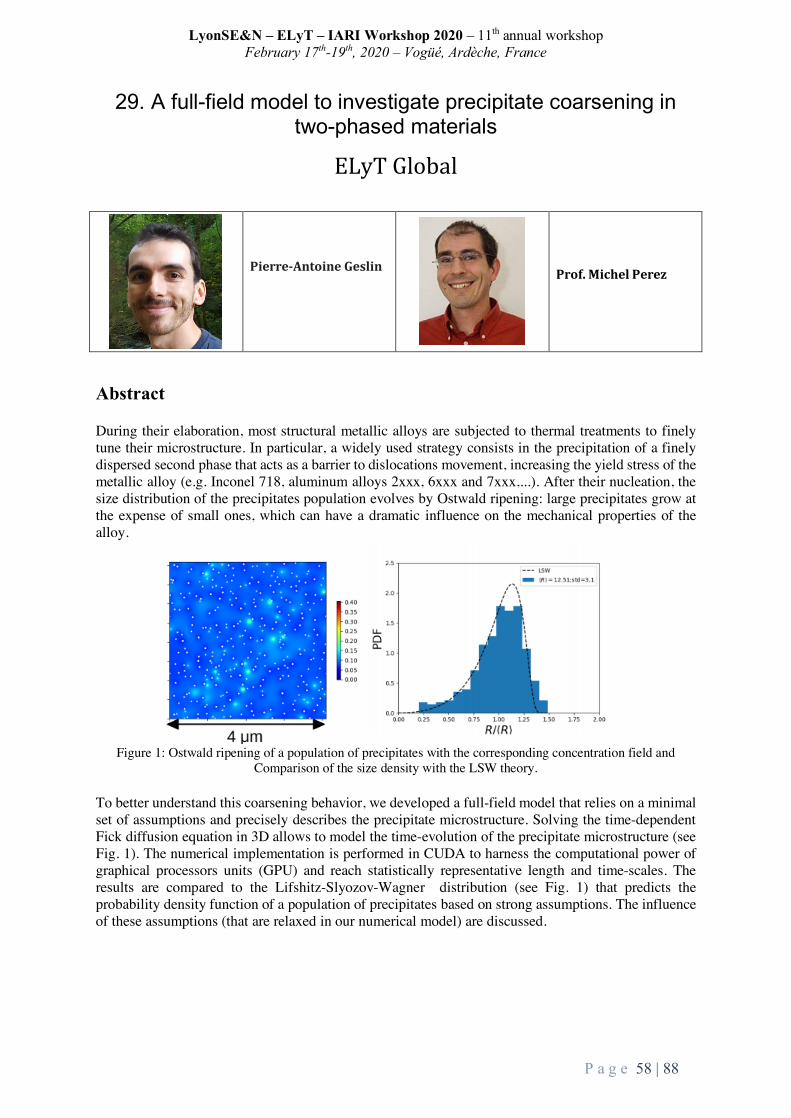
LyonSE&N – ELyT – IARI Workshop 2020 – 11th annual workshop February 17th-19th, 2020 – Vogüé, Ardèche, France
P a g e 58 | 88
29. A full-field model to investigate precipitate coarsening in two-phased materials
ELyTGlobal
Pierre-AntoineGeslin
Prof.MichelPerez
Abstract During their elaboration, most structural metallic alloys are subjected to thermal treatments to finely tune their microstructure. In particular, a widely used strategy consists in the precipitation of a finely dispersed second phase that acts as a barrier to dislocations movement, increasing the yield stress of the metallic alloy (e.g. Inconel 718, aluminum alloys 2xxx, 6xxx and 7xxx,...). After their nucleation, the size distribution of the precipitates population evolves by Ostwald ripening: large precipitates grow at the expense of small ones, which can have a dramatic influence on the mechanical properties of the alloy.
Figure 1: Ostwald ripening of a population of precipitates with the corresponding concentration field and
Comparison of the size density with the LSW theory. To better understand this coarsening behavior, we developed a full-field model that relies on a minimal set of assumptions and precisely describes the precipitate microstructure. Solving the time-dependent Fick diffusion equation in 3D allows to model the time-evolution of the precipitate microstructure (see Fig. 1). The numerical implementation is performed in CUDA to harness the computational power of graphical processors units (GPU) and reach statistically representative length and time-scales. The results are compared to the Lifshitz-Slyozov-Wagner distribution (see Fig. 1) that predicts the probability density function of a population of precipitates based on strong assumptions. The influence of these assumptions (that are relaxed in our numerical model) are discussed.

LyonSE&N – ELyT – IARI Workshop 2020 – 11th annual workshop February 17th-19th, 2020 – Vogüé, Ardèche, France
P a g e 59 | 88
30. Coarse-Grained Molecular Dynamics Study of Polymer Self-assembly in Dispersions for Polymer Electrolyte Fuel Cells
ELyTGlobal
Modeling-Simulation
Dr.TakuyaMabuchi
Prof.TakashiTokumasu
Abstract The cathode catalyst layer (CL) is one of the principal components for polymer electrolyte fuel cells. CL is typically prepared by drying a catalyst ink consisting of Pt-C (platinum on a carbon powder support), ionomer, and solvents (water/alcohol mixtures). The Pt-C particles are covered with aggregated ionomers of thin filmswhen the solutions are exposed to evaporation. The structure and stability of ionomer thin films are the key to the physical properties of CLs, including water distribution, proton conductivity, and oxygen diffusion. Thus, understanding the ionomer aggregation behaviors in solutions is of great importance to gain a deep insight into fundamental morphological characteristics of ionomer thin films. In this study, the characterization of ionomer self-assembly in a mixture of 1-propanol (NPA) and water have been investigated using coarse-grained molecular dynamics simulations. The dependence of NPA content on the ionomer structures was studied by systematically changing the NPA content in the system. The self-assembly behavior of ionomers into cylindrical bundle-like aggregates was observed and the aggregate size was found to be dependent on the NPA content in solutions. The ionomer concentrations were also found to show significant differences in aggregate structures.

LyonSE&N – ELyT – IARI Workshop 2020 – 11th annual workshop February 17th-19th, 2020 – Vogüé, Ardèche, France
P a g e 60 | 88
31. Tentative elucidation of physical mechanisms of soft polymer electrostriction
ELyTGlobalTEmPuRA14
Project: Theory for Electrostriction of PolymeRic Actuator:
o Theme: Materials and structure design
KaoriYuse1,4,GildasDiguet2,LaurenceSeveyrat1,VéroniquePerrin1,GildasCoativy1,ToshiyukiTakagi2,3,
Jean-YvesCavaillé2,41LGEF,UnivLyon,INSALyon,EA682,F-69621Villeurbanne,France2ELyTMaXUMI3757,CNRS–Univ.deLyon–TohokuUniv.,Internat.JointUnit,Sendai,Japan3InstituteofFluidScience(IFS),TohokuUniv,Sendai,Japan4IFSLyonCenter,ELyTMaX@LyonUMI3757,INSAVALOR,BP52132,69100Villeurbanne,France
Abstract The development of Electro-Active Polymers (EAPs) has attracted increasing interest in recent
decades due to its great advantages, such as its high level of deformation or flexibility, over other materials used to produce sensors or actuators. Most of these materials have been obtained by systematic screening, but very few studies have been conducted to understand the physical mechanisms underlying their behavior.
Under an electric field, E applied to some polyurethanes (PU), a compressive (negative) deformation S is generated. Unlike piezoelectric materials, this E-induced deformation is usually expressed with S=ME2 where M is called the electrostrictive coefficient. M was supposed to be mainly explained by the electrostatic force between the two electrodes, so-called Maxwell stress. However, the calculation of this stress leads to a deformation much lower than the values measured with the PU studied15. On the other hand, it is noteworthy that contrarily to the Maxwell strain contribution, experiments exhibit a very large time dependence as shown in Fig.1. This suggests that not only electrostatic mechanisms but also diffusion processes, like electrical conductivity, should be taken into account. In the case where the dielectric material is not homogeneous (spatial variations of dielectric constant, of local conductivity and elastic constants), we have shown that an additional contribution arises from interactions between molecular dipoles and electric field gradients. For PU di-block copolymers, phase separation occurs during film casting, which leads to a particle-matrix microstructure. In that case, additional time-dependent force field, acting on the particles, appears16. However, this contribution is smaller than that of the Maxwell strain and is not able to explain the experimentally obtained strain level. It is then interesting to compare with other electroactive behaviors, and among them, bending experiments have been rather well studied (Fig.2). The slow kinetics of bending are reported in the literature, and thus it
14Theory for Electrostriction of PolymeRic Actuator 15IlieDiaconu,Dana-OrtansaDorohoi,andFlorinTopoliceanu,ElectrostrictionofaPolyurethaneElastomer-BasedPolyester,IEEESensorsJournal(2006)6,876-880.16Exploringphysicalinsightsofelectrostrictivepolymers:contributionofthepolarizationbodyforces,G.Diguetetal.Tobepublished.

LyonSE&N – ELyT – IARI Workshop 2020 – 11th annual workshop February 17th-19th, 2020 – Vogüé, Ardèche, France
P a g e 61 | 88
appears interesting to study more intensively the conductivity features of these materials. Thus, the next step consists of showing the relationship between electrostriction and bending.
Fig.1:Conductivityversustimeunder106V/mDCvoltage,duringafirststep,thenafterinversionofthe
field.It is worthy to notice that the mechanisms described above, in addition to the fact they are too weak
to explain large electrostriction, would not introduce a dissymmetry between the two free surfaces of the samples: thus, they will not provide any driving forces responsible for the bending.
Fig.2:a)Schematicofbendingmeasurements17.b)ExperimentaldataforaDCstep(107V/m):redbending,bluecurrent.
It is noteworthy that kinetics may be very slow, which means that samples keep for a long time the memory of previous measurements, as shown in Fig. 1b. It shows the conductivity versus time with 100 V DC voltage, measured with AC voltage at 3.10-2 Hz.
Fig.3:a)Spacechargedensityalongwiththesamplethickness(from[3]);b)BendingsimulatedwithComsol.c)Electrostrictionincompressioncorrespondingtothebendingofb).Thearrowsindicatethe
intensityofthedisplacement
From these preliminary results, it seems clear that the diffusion of electrical charges under the applied field is responsible for the macroscopic deformation of the samples. If the kinetics of positive and negative carriers are different, their concentration in the vicinity of the electrodes is different. The consequence is that the repulsive electrostatic forces induce the stretching of material near these surfaces, with different intensity, which in turn induces the bending. On the other hand, stretching the subsurface of the sample leads to a thickness decrease, as observed in electrostriction measurements. Works are now ongoing to quantitatively evaluate the various parameters involved in such mechanisms.
17Watanabe,M.,&Hirai,T.(2004).Bending-electrostrictiveresponseofpolyurethanefilmssubjectedtoareversedelectricfield.JournalofAppliedPolymerScience,92(6),3644–3650.doi:10.1002/app.20300

LyonSE&N – ELyT – IARI Workshop 2020 – 11th annual workshop February 17th-19th, 2020 – Vogüé, Ardèche, France
P a g e 62 | 88
32. Materials for High field magnets
ELyTGlobal
XavierCHAUD
Magnetdevelopment@LNCMI-Grenoble
FrançoisDEBRAY
Magnetdevelopment@LNCMI-Grenoble
FlorenceLECOUTURIER
Magnetdevelopment@LNCMI-Grenoble
Abstract Few facilities worldwide offer access to researchers to high magnetic fields in excess of what can be obtained by superconducting electromagnet available on the market. This is the case of the LNCMI in France and the High field Laboratory in Sendai, Tohoku University. Materials developed for these high field electro-magnets have to withstand different constraints: a) theLorentzforcearisingfromthecrossingofcurrentandmagneticfieldlines,b)theJouleeffectoccurringwhenacurrentpassesthrougharesistiveconductor.Additionallyintheparticularcaseofsuperconductingmaterials,theavailableenergycannourishphasetransitionsthatdestroythesuperconductingstate.Therefore,toproducemagneticfieldinexcessof30tesla(T),highstrengthandhighlyconductivematerialshavetobeused.ForthispurposeatLNCMIincollaborationwithICB/UTBMwehaveadaptedthe“coldspray”methodtoproducecopperalloytubeswithyieldstrength>500MPaandelectricalconductivity>50MS.m-1.Theseperformancesarewellbeyondmarketstandardsandthesenewmaterialsarenowusedfortheproductionofmagneticfieldupto37T.Inparallelweplantoconstructapurelysuperconductingmagnetinexcessof30TwhichwillbemadeofacentralCupratehighTcsuperconductormagnetnestedinalargeboreNbbasedlowTcsuperconductor. A focus will also be given on the collaboration going on between the two high field facilities in France and in Japan.

LyonSE&N – ELyT – IARI Workshop 2020 – 11th annual workshop February 17th-19th, 2020 – Vogüé, Ardèche, France
P a g e 63 | 88
33. Magneto Rheological Elastomers and the effect of the particles filling factor
ELyTGlobalMARECO
Smart materials Energy harvesting
Gildas Diguet1,2, Gaël Sebald1, Masami Nakano1,3, Mickael Lallart1,2,4, Jean-Yves Cavaillé1 1ELyTMaX UMI 3757, CNRS-Université de Lyon-Tohoku University International Joint Unit, Tohoku University, Sendai, Japan 2Institute for Fluid Science, Tohoku University, Sendai, Japan 3New Industry Creation Hatchery Center, Tohoku University, Sendai, Japan 4Univ. Lyon, INSA-Lyon, LGEF EA682, F69621 Villeurbanne, FranceAbstract Magneto rheological elastomers (MREs) couple high elasticity of the silicone rubber elastomer matrix with strong magnetization of embedded iron particles, allowing highly deformable smart materials. In this report, we investigate on the application of this material for converting mechanical vibrations into electrical signal, with a special focus on the impact of filler factor. 1. Introduction In the framework of energy conversion, Magneto Rheological Materials (MRE) are notably used as tunable damping materials. Indeed, thanks to ferromagnetic particles inside the soft elastic matrix, the elastic properties of this composite are varying with the application of a magnetic field. This is known as MR effect. A lesser known effect, called pseudo-Villari effect, consists in the change of the magnetic properties due to the application of mechanical strain. Such a feasibility of converting a mechanical strain into electrical signal has been successfully demonstrated [1-3]. An energy converter demonstration system is designed as a magnetic yoke with a gap filled by two anisotropic MREs submitted to mechanical oscillation strain. Because of the pseudo-Villari effect, the magnetic state of these MREs is varying as they are strained, and a coil is then used for producing an electrical signal from the change in magnetic flux. In this work we present how the filling particles impact the pseudo-Villari effect. 2. Experimental MRE composites are based on Silicon Rubber (SR) KE-1241 combined with a curing agent CLA-9 purchased from Shin-Etsu Chemical Co. Ltd. (Tokyo, Japan). The magnetic spherical particles are Carbonyl Iron (CIP) from BASF, with average diameter of 2a= 6-7 µm. Particles were mixed in liquid silicone with different quantities ({5, 10, 15, 25} vol%), and the mixture was cured under a constant magnetic field of 0.3 T to produce anisotropic composites, labeled as MRE05, MRE10, MRE15, MRE20 and MRE25 respectively. The device is presented in Fig. 1, which consists of an excitation coil for magnetizing the MREs and a steel blade used to apply the strain on the two MRES. A pick-up coil is added in order to convert the magnetic flux variation into electrical voltage. The soft ferromagnetic circuit cross section is 5 × 1.2 cm2 with a length of 20 cm, the steel blade thickness 1 mm, the sample

LyonSE&N – ELyT – IARI Workshop 2020 – 11th annual workshop February 17th-19th, 2020 – Vogüé, Ardèche, France
P a g e 64 | 88
thickness 2 mm, winding numbers are 1560 for the excitation coil and 300 for the search coil. Applied sine displacement to the steel blade was recorded along with the force to extract the MRE strain and stress. The generated electrical signal is also recorded on the search coil.
Fig.1. Device for conversion of the mechanical
vibration into electrical signal. Fig.2. Amplitude of voltage Vs for each MRE, (i.e., each
filing factor), at different strain amplitude (γ0) and applied field (B0) [4].
3. Results As the applied displacement strained the two MREs under a bias field B0, their own magnetic properties were varying. As a result, a time dependent magnetic flux is flowing in the circuit and is converted into electrical signal by the search coil. These electrical signal amplitudes Vs are plotted in Fig. 2 as a function of the applied field, for each filling factor and at different applied strain amplitudes γ0. It can be seen that an optimal field exists that maximizes Vs, around 0.2-0.3T. As the strain amplitude (γ0) is increased, the values of Vs increased too. Finally, it can be observed that MRE20 and MRE25 presented similar values for Vs [4]. 4. Conclusion The production of electric signal is demonstrated. The amplitude of the signal is increase with the applied strain. However, optimal values are found for the applied field and the signal increases no longer for MRE with fraction larger than 20% (vol.). Acknowledgements This project is supported by French Agence Nationale de la Recherche, Investissements d’Avenir, Project IDEXLyon of the Université de Lyon [grant number ANR-16-IDEX-0005]. M. Lallart gratefully acknowledges the support of JSPS through invitational fellowship grant number L19530, as well as INSA-Lyon for its support through the CRCT program. References: [1] Mickael Lallart, Gael Sebald, Gildas Diguet, Jean-Yves Cavaille and Masami Nakano. J. Appl. Phys. 122, 103902 (2017). [2] Gael Sebald, Masami Nakano, Mickael Lallart, Tongfei Tian, Gildas Diguet, Jean-Yves Cavaille. Science and Technology of Advanced Materials, 2017 Vol. 18, No. 1, 766–778 [3] Gildas Diguet, Gael Sebald, Masami Nakano, Mickaël Lallart, Jean-Yves Cavaille, J. Magnet Magnet Mat, 481 (2019) 39-49. [4] Gildas Diguet, Gael Sebald, Masami Nakano, Mickaël Lallart, Jean-Yves Cavaille, Smart Materials and Structures. under review.

LyonSE&N – ELyT – IARI Workshop 2020 – 11th annual workshop February 17th-19th, 2020 – Vogüé, Ardèche, France
P a g e 65 | 88
34. Influence of ammonia addition on stabilization of methane jet diffusion flames.
ELyTGlobal
Energy Science and technology for utilizations of carbon free energy carriers
Prof.EscudieProf.GalizziProf.Kuhni
Prof.Kobayashi
SophieColson(DoubledegreePh.D.Student)
Abstract 1. Introduction Ammonia has recently gained attention as a promising carbon-free fuel. Its production from renewable resources, known as green ammonia production, combining water electrolysis and the Haber-Bosch process, yields no carbon emissions [1]. The characteristics of ammonia (liquid at 9 bars in room temperature conditions) makes its transportation and storage comparable to most of the currently used hydrocarbons. Ammonia is thus especially competitive carbon-free energy vector when considering its production, transportation and storage costs relatively to hydrogen. Because of its use in agro-industry, the production and transportation process of ammonia is well-established, making the deployment of ammonia as an energy vector possible in the near future. The use of ammonia in combustion applications, as a mean for carbon emission reduction, is thus really promising and has been the subject of recent studies [2-5]. Recent demonstration of the use of ammonia in a micro-gas-turbine application [6] showed the feasibility of such applications. However, NOx emission and flame stabilization remains two main challenges for the development of ammonia combustion and need to be further investigated. In this study, the use of an ammonia-methane blend is considered as a mean for the progressive introduction of ammonia in existing industrial burners, lowering carbon emissions while ensuring flame stabilization. Those blend being poorly known, the study of their fundamental combustion characteristics is essential [7, 8]. Jet flames have a relatively simple structure and had been the subject numerous studies [9-11] as they are close to a number of industrial applications. Flame stabilization has thus been investigated by the mean of a methane jet diffusion flame, with gradual addition of ammonia. 2. Method The jet burner used in this study is the same as described in previous work [9]. For such type of configuration, two types of stabilization can be observed: for relatively low jet velocity, flame is stabilized close to the burner lip corresponding to attached flame regime; when increasing the jet velocity, the flame is blown off and stabilizes further downstream corresponding to lifted flame regime as presented in Fig. 1. Further increase in the velocity of the jet leads to a blow out of the flame. Lifted flame might also get re-attached to the burner lips if the velocity is decreased sufficiently, showing a hysteresis behavior as introduced in [9]. Transitions velocity between those regimes are of particular importance for the design of combustors [9]. Evolution of the lifting velocity, Ul, as well as the re-attachment velocity, Ua, has thus been observed for various fuel mixing ratio, E, as defined in (1), where 𝑋* the mole fraction of species i and 𝐿𝐻𝑉* the low heating value of i.
E = DEFGHIJEFG
DEFGHIJEFGKDLFMHIJLFM (1)
3. Preliminary results The results on transition velocities are presented in Fig. 1 with respect to fuel mixing ratio E for a coflow

LyonSE&N – ELyT – IARI Workshop 2020 – 11th annual workshop February 17th-19th, 2020 – Vogüé, Ardèche, France
P a g e 66 | 88
velocity, Uco, of 0.2 m/s. It was observed that both Ul and Ua decreased with an increase in the ammonia content in the fuel mixture. The decrease in the lifting velocity is consistent with the decrease in laminar burning velocity observed in [7]. The introduction of ammonia into the mixture leads to a decrease in the burning velocity as well as the flame temperature leading to earlier lift. The lifting process is thus strongly affected by the change in the chemistry associated with the change in the fuel mixture. The re-attachment velocity presents a slightly different behavior: while being merely affected by the ammonia introduction at first, an important transitional behavior his observed for a specific value of E. This value of E, near E = 0.15 for Uco = 0.2 m/s, was shown to be dependent on the coflow velocity, Uco: for larger Uco, the transition appeared for smaller E and vice versa. No similar behavior was observed in the lifting velocity evolution. This specific behavior was related to the evolution of the lift-off height of the flame, increasing in the transition turbulent to laminar of the jet (represented in grey in Fig. 1), for a sufficiently large value of Uco. The apparition of this specific behavior, for flames above a critical lifting height, HLc, and for coflow velocity above a critical velocity,Ucr , will be further investigated.
Figure 1. Transition regimes evolution with ammonia content; direct images of flames: (a) attached
flame E = 0.1, (b) lifted flame E = 0.1. References [1] Y. Bicer, I. Dincer, C. Zamfirescu, G. Vezina, and F. Raso, “Comparative life cycle assessment of various ammonia production methods,” J. Clean. Prod., vol. 135, pp. 1379–1395, 2016. [2] A. Valera-Medina, H. Xiao, M. Owen-Jones, W. I. F. David, and P. J. Bowen, “Ammonia for power,” Prog. Energy Combust. Sci., vol. 69, pp. 63–102, 2018. [3] H. Kobayashi, A. Hayakawa, K. D. K. A. Somarathne, and E. C. Okafor, “Science and technology of ammonia combustion,” Proc. Combust. Inst., vol. 37, no. 1, pp. 109–133, 2019. [4] K. D. K. A. Somarathne, A. Hayakawa, and H. Kobayashi, “Numerical investigation on the combustion characteristics of turbulent premixed ammonia/air flames stabilized by a swirl burner,” Journal Fluid Sci. Technol., vol. 11, no. 4, paper no. 16-00126, 2016. [5] E. C. Okafor, K. D. K. A. Somarathne, A. Hayakawa, T. Kudo, O. Kurata, N. Iki, and H. Kobayashi, “Towards the development of an efficient low-NOx ammonia combustor for a micro gas turbine,” Proc. Combust. Inst., vol. 37, no. 4, pp. 4597–4606, 2019. [6] O. Kurata, N. Iki, T. Inoue, T. Matsunuma, T. Tsujimura, H. Furutani, M. Kawano, K. Arai, E. C. Okafor, A. Hayakawa, and H. Kobayashi, “Development of a wide range-operable, rich-lean low-NOx combustor for NH3 fuel gas-turbine power generation,” Proc. Combust. Inst., vol. 37, no. 4, pp. 4587–4595, 2019. [7] E. C. Okafor, Y. Naito, S. Colson, A. Ichikawa, T. Kudo, A. Hayakawa, and H. Kobayashi, “Experimental and numerical study of the laminar burning velocity of CH4–NH3–air premixed flames,” Combust. Flame, vol. 187, pp. 185–198, 2018. [8] C. Okafor, Y. Naito, S. Colson, A. Ichikawa, T. Kudo, A. Hayakawa, and H. Kobayashi, “Measurement and modeling of the laminar burning velocity of methane-ammonia-air flames at high pressures using a reduced reaction mechanism,” Combust. Flame, vol. 204, pp. 162–175, 2019. [9] D. Escudié, F. André, F. Baillot, K. M. Lyons, J. Min, S. Lamige, and C. Galizzi, “On preheating and dilution effects in non-premixed jet flame stabilization,” Combust. Flame, vol. 160, no. 6, pp. 1102–1111, 2013. [10] G. T. Kalghatgi, “Lift-off heights and visible lengths of vertical turbulent jet diffusion flames in still air,” Combust. Sci. Technol., vol. 41, no. 1–2, pp. 17–29, 1983. [11] B. J. Lee, J. S. Kim, and S. H. Chung, “Effect of dilution on the liftoff of non-premixed jet flames,” Proc. Combust. Inst., vol. 25, no. 1, pp. 1175–1181, 1994.

LyonSE&N – ELyT – IARI Workshop 2020 – 11th annual workshop February 17th-19th, 2020 – Vogüé, Ardèche, France
P a g e 67 | 88
35. Evolution of microstructure and mechanical properties with thermomechanical treatments of new Ti-Mo-Zr-Sn β-titanium
alloys for biomedical applications
ELyTGlobalNewProject
Health
Materials and Structure design
ManonLaurençonDoublePhDstudent INSA - TU
INSAdeLyon,MATEISLaboratoryTohokuUniversity,[email protected]
Prof.DamienFabrègueSupervisor
INSAdeLyon,InternationalRelationships,Building
CharlottePerriand,3rdfloor,17Av.desArts
69621Villeurbanne,France
Prof.AkihikoChibaSupervisor
ChibaLaboratory,DeformationProcessing,InstituteforMaterials
Research,TohokuUniversity,2-1-1Katahira,Aoba-ku,Sendai,980-8577Japan
Abstract Accountingforthewell-knownlimitsofcurrentlyusedmaterialsforbodyimplantologysuchasTA6V-ELI,thedevelopmentofnewmaterialsforthistypeofapplicationbecameakeyissuesinceseveral years now. In this context, new quaternary metastable β-titanium alloys have beendesignedusingthe“d-electron”methoddevelopedbyMorinaga.ConsistingofTi-Mo-Zr-Snalloys,theymayrepresentnewalternativesforthishighlyrequiringapplication,aiminghighmechanicalstrength,largeductilityandworkhardeningwhilekeepingexcellentbiocompatibility.Toachievethiscompromise,thealloysweredesignedtocombinebothTWinningInducedPlasticity(TWIP)andTRansformationInducedPlasticity(TRIP)underloading,inordertoimproveductilityandwork hardening on one hand. On the other hand, mechanical strength enhancement waspromotedusingisothermalω-phaseprecipitationbasedonthethermalbehaviourofthealloysafterDSCexperiments.Thus,flashagingsatdifferenttemperatureswithincreasingtimeswereconductedon fully recrystallizedalloyswithbetagrains, so that optimalωparticles sizeanddistributioncanbeobtained.Thephysicalpropertiesandmechanicalbehavioursofsuchalloyshavebeenassessedafterhotrolling,recrystallizationandωprecipitation.MicrostructureswerecharacterizedusingEBSD,XRD,EPMAandTEM.Hardnessandtensiontestswerethenconductedunder every conditions, followed by fracture surface analysis (OM, SEM) and activateddeformation mechanisms detection (EBSD, XRD). Among the designed alloys, three of themshowed attractive mechanical properties for biomedical applications, combining quite goodstrengthwithlargerductilityandworkhardeningthanTA6V-ELI.

LyonSE&N – ELyT – IARI Workshop 2020 – 11th annual workshop February 17th-19th, 2020 – Vogüé, Ardèche, France
P a g e 68 | 88
36. A database of structured meshes for computational fluid dynamics in large cerebral arterial networks.
ELyTGlobal
Engineering for health Simulation & Modeling
MéghaneDecroocq
INSALyon(LIRIS,CREATIS,ELyTMax)/TohokuUniversity(OhtaLab)
Prof.GuillaumeLavoué
LIRIS,INSALyon
Prof.CaroleFrindel
CREATIS,INSALyon
Prof.MakotoOhta
ElyTMax,IFS,TohokuUniversity
Abstract In the biomedical engineering field, computational fluid dynamics (CFD) simulation enables to study the relation between vessel geometry and blood flow. The resolution of fluid dynamics equations in three dimensions requires the fluid domain to be divided into cells to form a discretized computational mesh. The method commonly used to produce a patient-specific boundary surface from medical images requires several steps [1] (e.g image filtering and segmentation, surface meshing, smoothing) which implies user interaction and impacts the accuracy of the geometry. Moreover, due to their ability to mesh automatically very complex shapes, unstructured meshes (with unorganized cells) are widely used, although they lead to higher computational cost and less accurate results. Therefore, meshing is still a bottleneck in blood flow simulation, especially for large vascular networks. Our goal is to provide a database of high quality meshes of the whole cerebral arterial network, ready for CFD analysis. The patient data used in this work was taken from the open database braVa [2], where 60 vascular tree skeletons were manually extracted from magnetic resonance angiography images. Structured tubular meshes were generated using an automatic procedure. The arterial segments were first approximated by splines and the bifurcation parts were modeled following the method of Ghaffari et al. [3]. The surfacic and volumic meshes were finally computed according to the spline tangent information, resulting in flow-aligned hexahedral cells. The meshes can be directly used to perform computational fluid dynamics, stent deployment or fluid-solid interaction simulations. It can also be deformed to model different vessel pathology (e.g stenosis, occlusion, aneurysm) or merged to other patient specific arterial meshes to achieve more accurate boundary conditions. The automatic meshing algorithm is also suitable for the generation of

LyonSE&N – ELyT – IARI Workshop 2020 – 11th annual workshop February 17th-19th, 2020 – Vogüé, Ardèche, France
P a g e 69 | 88
new patient specific meshes, provided that the skeleton was previously extracted from angiography volume, which makes it an interesting tool to save time on the meshing step. Acknowledgement
This work has been supported by the Région Auvergne-Rhône-Alpes through the “Pack Ambition Internationale” action. The thesis of M. Decroocq is co-funded by INSA Lyon and ElyTMax.
References [1] Lesage, D., Angelini, E. D., Bloch, I., & Funka-Lea, G. (2009). A review of 3D vessel lumen segmentation techniques: Models, features and extraction schemes. Medical image analysis, 13(6), 819-845. [2] Wright, S. N., Kochunov, P., Mut, F., Bergamino, M., Brown, K. M., Mazziotta, J. C., ... & Ascoli, G. A. (2013). Digital reconstruction and morphometric analysis of human brain arterial vasculature from magnetic resonance angiography. Neuroimage, 82, 170-181. [3] Ghaffari, M., Hsu, C. Y., & Linninger, A. A. (2015). Automatic reconstruction and generation of structured hexahedral mesh for non-planar bifurcations in vascular networks. In Computer Aided Chemical Engineering (Vol. 37, pp. 635-640). Elsevier.

LyonSE&N – ELyT – IARI Workshop 2020 – 11th annual workshop February 17th-19th, 2020 – Vogüé, Ardèche, France
P a g e 70 | 88
P1. Angiography-based Velocimetry for Blood Flow
ELyTGlobal
Medical Applications Simulation
Abstract
1 Introduction An arteriovenous fistulas (AVF) is an abnormal connection between arteries and veins. When
it occurs in pia mater, it is referred to as a pial AVF. Pial AVFs display high rates of morbidity and mortality. In one report, five (63%) of eight conservatively treated patients with pial AVF died [1]. Most AVFs can be treated with surgery, in which the feeding arteries are occluded by clipping the surface vessels [2]. However, high flow rates and deep venous drainage limit the safety and efficacy of surgical treatment [3]. As a less-invasive alternative, endovascular treatments can be used to occlude the artery connections with embolization agent injected from an intravascular catheter. However, even a perfectly injected embolization agent may migrate due to the high blood flow rate that is characteristic of AVFs [4]. Furthermore, the high flow inside a pial AVF tends to form a venous varix, therefore, the quantitative estimation of hemodynamics in pial AVF may be useful for the diagnosis or the treatment planning.
By applying optical flow method (OFM) [5] to digital subtracted angiography (DSA) images, blood flow velocity can be estimated [6,7]. However, the velocity of flow is calculated from the movement of contrast medium in 2D images [6]. Therefore, 3D flow cannot be fully resolved by this method.
In this study, angiography-based velocimetry will be developed aiming at the estimation of the 3D velocity distribution in brain vessels. For this aim, we analyze the influence of acquisition parameters of angiography on velocity estimation and perform 3D extension of angio-velocity based on vessel geometry.
2 Method 2.1 Obtaining angiography images under different acquisition conditions
For analyzing the effect of acquisition parameters, angiography images were simulated, using the following three steps; 1) performing a steady CFD simulation to reproduce blood flow, 2)
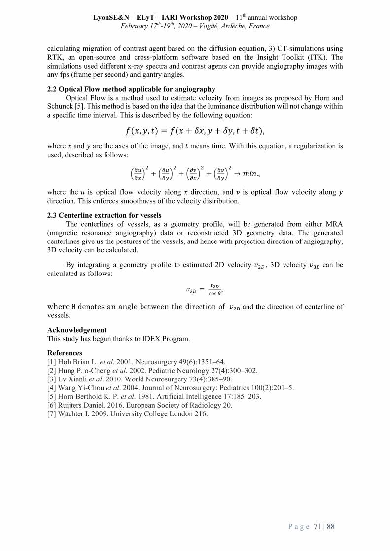
LyonSE&N – ELyT – IARI Workshop 2020 – 11th annual workshop February 17th-19th, 2020 – Vogüé, Ardèche, France
P a g e 71 | 88
calculating migration of contrast agent based on the diffusion equation, 3) CT-simulations using RTK, an open-source and cross-platform software based on the Insight Toolkit (ITK). The simulations used different x-ray spectra and contrast agents can provide angiography images with any fps (frame per second) and gantry angles.
2.2 Optical Flow method applicable for angiography Optical Flow is a method used to estimate velocity from images as proposed by Horn and
Schunck [5]. This method is based on the idea that the luminance distribution will not change within a specific time interval. This is described by the following equation:
𝑓(𝑥, 𝑦, 𝑡) = 𝑓(𝑥 + 𝛿𝑥, 𝑦 + 𝛿𝑦, 𝑡 + 𝛿𝑡),
where 𝑥 and 𝑦 are the axes of the image, and 𝑡 means time. With this equation, a regularization is used, described as follows:
TUVUWX;+ TUV
UYX;+ TUZ
UWX;+ TUZ
UYX;→ 𝑚𝑖𝑛.,
where the 𝑢 is optical flow velocity along 𝑥 direction, and 𝑣 is optical flow velocity along 𝑦 direction. This enforces smoothness of the velocity distribution.
2.3 Centerline extraction for vessels The centerlines of vessels, as a geometry profile, will be generated from either MRA
(magnetic resonance angiography) data or reconstructed 3D geometry data. The generated centerlines give us the postures of the vessels, and hence with projection direction of angiography, 3D velocity can be calculated.
By integrating a geometry profile to estimated 2D velocity 𝑣;b , 3D velocity 𝑣cb can be calculated as follows:
𝑣cb = Zdefgh i
,
where θ denotes an angle between the direction of 𝑣;b and the direction of centerline of vessels.
Acknowledgement This study has begun thanks to IDEX Program.
References [1] Hoh Brian L. et al. 2001. Neurosurgery 49(6):1351–64. [2] Hung P. o-Cheng et al. 2002. Pediatric Neurology 27(4):300–302. [3] Lv Xianli et al. 2010. World Neurosurgery 73(4):385–90. [4] Wang Yi-Chou et al. 2004. Journal of Neurosurgery: Pediatrics 100(2):201–5. [5] Horn Berthold K. P. et al. 1981. Artificial Intelligence 17:185–203. [6] Ruijters Daniel. 2016. European Society of Radiology 20. [7] Wächter I. 2009. University College London 216.

LyonSE&N – ELyT – IARI Workshop 2020 – 11th annual workshop February 17th-19th, 2020 – Vogüé, Ardèche, France
P a g e 72 | 88
P2. Application of the modal decomposition technique to a subsonic jet numerical database
ELyTGlobalNewProject
Transportation
Modeling&Simulation
ShotaMORITAM1StudentAerospaceFluidEngineeringLab.IFS/TohokuUniv.JAPAN
AikoYAKENO,Ph.D.AssistantProfessorAerospaceFluidEngineeringLab.IFS/TohokuUniv.JAPAN
ChristopheBogey,Ph.D.DirecteurdeRechercheCNRSLaboratoiredeMécaniquedesFluidesetd'AcoustiqueECL,France
ShigeruOBAYASHI,Ph.D.ProfessorAerospaceFluidEngineeringLab.IFS/TohokuUniv.JAPAN
Abstract 1. Introduction
Aeroacoustics, particularly jet noise is caused by turbulent vortices, generated by the unsteady and non-linear motion of the turbulence itself. This makes it difficult to understand the origin and the mechanism of sound generation. In this study, we try to develop a good way to extract significant flow characteristics to represent a sound source quantitatively. Some researchers [1,2,3] have applied principal component analysis to the flows, such as the snapshot proper orthogonal decomposition (snapshot POD [4]) technique. Snapshot POD is one of the modal decomposition techniques, which can extract characteristic components from complicated unsteady flow data, and reconstruct them as a reduced- order model. In this study, we apply a fast Fourier transform (FFT) to numerical data obtained for a subsonic jet by Dr. Christophe Bogey using direct numerical simulation [5] , and compare results with those of the snapshot POD to understand the feature, as the first step.
2. Problem Settings In our approach, we used two-dimensional flow data that were originally computed as a three-dimensional isothermal round jet. A snapshot of the pressure field of the presented data is shown in Fig.1. The flow conditions are shown in table 1, where 𝑟l means the jet radius. The values reported herein were nondimensionalized by the jet radius and the inlet centerline velocity.
In the FFT, we analyzed the data at two points (a) 𝑟=0, 𝑧=15𝑟l and (b) 𝑟=40𝑟l, 𝑧=15𝑟l, as shown in Fig.1. Point (a) indicates the end of the potential core, which is known as the noise source [5] and (b) is the position of the pressure wave that propagated from (a). In the snapshot POD, we considered a time-series of 1000 (about 8% of whole data set)

LyonSE&N – ELyT – IARI Workshop 2020 – 11th annual workshop February 17th-19th, 2020 – Vogüé, Ardèche, France
P a g e 73 | 88
density, pressure and three-velocity data of whole domain. Table 1. Flow conditions [5]
Mach number Reynolds number Time step (nondimensional) 0.9 3125 0.079
Fig.1 Instantaneous distribution of pressure (p), from 0.8(blue) to 1.01(red).
3. Results and Discussion
The results of the FFT are shown in the Fig. 2 for positions (a) and (b) given in the Fig. 1. The vertical line shows the power spectra density and horizontal line shows the Strouhal number St that is expressed as a nondimensionalized frequency. According to the Fig. 2, we can see that the pressure perturbation at r=0,z=15𝑟lhas a wide peak ranging from St=0.01 to 0.5, which is thought to arise from vortices with different overlapping frequencies in this area. Moreover, for r=15𝑟l,z=40𝑟l, we can see a narrow peak around St=0.3, which is the frequency of the pressure wave that propagated from the end of the potential core.
Next, we displayed the results of the snapshot POD in the Fig.3. The percentage value in the figure captions is the contribution rate that is a criterion related to the dominant mode, simply based on the spatial integration of five squared variables in the whole domain. In the first mode (a), although it contributes the most (11.7[%]), no clear periodicity was observed in the contour. This was also not seen such as pressure wave even if the contour range is changed. Moreover, vortex-like structures are absent in the streamwise direction in the original flow field. However, it seems that multiple vortex structures overlap, as seen in the FFT results near the potential core at r=0,z=15𝑟l. In the second mode (b) shown in Fig. 3 vortices have been generated. Same-sized vortices were extracted as those observed in the original data that resemble a wave packet-like structure which is thought to affect the generation of low-frequency noise that dominates the downstream[6], although its relationship to the acoustic field is unclear. Additionally, small vortex structure can be observed near the inlet in the 10th mode (c) that are the same size as those observed in the original data. Finally, sound propagation waves were confirmed in the 100th mode (d), although their contribution rate was relatively small.
The contribution rate represents the dominance to reconstruct the flow field, but it does not always represent the characteristics of the sound generation. A suitable evaluation strategy is left for future analyses.
Fig.2. Results of FFT of original data at r=0,z=15𝑟l and r=15𝑟l,z=40𝑟l
10-2 10-1 100 10110-1410-1310-1210-1110-1010-910-810-710-610-510-410-310-2
r=0,z=15 r=15,z=40
Strouhal number
PSD

LyonSE&N – ELyT – IARI Workshop 2020 – 11th annual workshop February 17th-19th, 2020 – Vogüé, Ardèche, France
P a g e 74 | 88
(a)Mode1(11.7%) (b)Mode2(6.5%)
(c)Mode10(2.8%) (d)mode100(0.0689%)
Fig.3. Results of the most two dominant modes (a), (b) and two characteristic modes (c), (d). The color scale ranges between ±0.002, from blue to red.
References [1]Tinney, C. E., Glauser, M. N. & Ukeiley, L. S.: Lowdimensional characteristics of a transonic jet.
Part 1. Proper orthogonal decomposition, J. Fluid Mech. 612 (2008) 107–141. [2]Tinney, C. E., Ukeiley, L. S. & Glauser, M. N.: Lowdimensional characteristics of a transonic jet.
Part 2. Estimate and far-field prediction, J. Fluid Mech. 615 (2008) 53–92. [3] Ryu, J. and Lele, S. K. & Viswanathan, K.: Study of supersonic wave components in high-speed
turbulent jets using an LES database, J. Sound Vib. 333 (2014) 6900-6923. [4] Sirovich, L.: Turbulence and the dynamics of coherent structures, Parts I–III. Q. Appl.
Math.XLV(1987) 561–590. [5] Bogey, C.: Two-dimensional features of correlations in the flow and near pressure fields of Mach
number 0.9 jets, 57th AIAA Aerospace Sciences Meeting (2019), AIAA Paper 2019-0806. [6] Panda, J., Seasholtz, R. G. & Elam, K. A.: Investigation of noise sources in high-speed jets via
correlation measurements, J. Fluid Mech., Vol. 537 (2005) 349–385.
LyonSE&N – ELyT – IARI Workshop 2020 – 11th annual workshop February 17th-19th, 2020 – Vogüé, Ardèche, France
P a g e 75 | 88
P3. Fully Partitioned Fluid-structure Interaction Analysis for Aircraft Wings ELyTGlobal
Simulation&Modeling
Iori SHOJI Graduate School of engineering, Tohoku Univ., 6-6 Aramaki aza Aoba, Aoba-ku, Sendai,980-8579,
Japan
Yoshiaki ABE Assistant Professor,
Institute of Fluid Science, Tohoku Univ., 2-1-1
Katahira Aoba-ku, Sendai, Japan
Tomonaga OKABE Professor, Tohoku
Univ., 6-6 Aramaki aza Aoba, Aoba-ku, Sendai,
980-8579, Japan
Abstract Introduction
Aero-structural design optimization of aircraft wings using a fluid-structure interaction (FSI) analysis is getting increased for designing more fuel-efficient aircrafts, which is recently based on the composite material as primary structures. In such composite aircrafts, multi-scale analysis that integrates aerodynamic structure optimization, strength evaluation, and tools for predicting material properties is often required due to the complicated properties of composite materials [1]. Therefore, it is necessary to efficiently perform a large-scale analysis for a huge number of parameters in optimization. For the coupled analysis in the FSI, several partitioned coupling approaches suitable for a parallel computation have been proposed based on a staggered method [2]. However, most of the parallelization techniques rely on a domain decomposition concept that requires a considerable number of communications between different computational nodes typically via an MPI (Message Passing Interface) process and thus burdens the total computation [3]. Nevertheless, there is a strong demand for applying higher-fidelity simulation to predict more complicated (multi-scale / multi-physics) problems that needs highly parallelizable implementation to reduce the total computational cost. In this study, we propose a new methodology so that the parallelization can be inherently applied to the coupled analysis itself, and verify its application to realistic problems such as aeroelastic simulation of aircraft wings. Coupled analysis suitable for parallel calculation
In general, a FSI problem is solved by a monolithic approach or a partitioned approach to satisfy an equilibrium condition between two systems. The schematic of the proposed method is shown in Fig.1. In general formulation, we first define a shape parameter that represents the boundary shape between two systems, which also prescribes an unsteady motion of the boundary shape. Here, we assume that the shape parameter can approximately represent the boundary shape in the coupled state. The residual of the coupled system at Nth sample points with different shape parameters is shown as:
,where F is the monitoring variable of each system (e.g., force, momentum), k is the shape control parameter, ϕis the modal vector of structure system, and r is the displacement vector at the interface ∂Ω between fluid-structure domain. Using a curve fitting and optimization, the residual can be solved as a residual minimization problem. Then, sampling parameter at minimum point used as a deformed shape condition approximately satisfies the equilibrium condition. The assumed shape can be used as a displacement boundary condition in the CSD solver and also used as a grid deformation in the CFD solver.
Considering the difference of spatial discretization methodology between both systems, the residual operator is evaluated at the same structure node points. At this time, the force field information which obtained by the fluid calculation is interpolated into the structure node by data transfer method. In addition, a coupled system is constructed with independent tool and an asymptotic strongly coupled solution is estimated using curve fitting and optimization methods (such as Kriging response surface).
res. fluid struct .( , ( , , )) ( , ( , , )) ( , ( , , ))N N NF t t k F t t k F t t kf f f¶W ¶W ¶Wº +r r r

LyonSE&N – ELyT – IARI Workshop 2020 – 11th annual workshop February 17th-19th, 2020 – Vogüé, Ardèche, France
P a g e 76 | 88
Fig.1.Basicconceptoffullypartitionedcoupling.
Configuration of aerodynamic model At First, the present method applied to an analytical aerodynamic model for flutter boundary prediction. The
calculation is demonstrated with both monolithic and present method. The assumed mode parameter defined as an eigenvalue in this case. The prediction result is shown in Fig.2. Using the kriging model, the minimum point of the response surface approximates the fully coupled solution.
Fig.2.Aerodynamicmodel/resultoftheflutterboundarycondition.
Application for static aeroelastic problem
The present coupled CFD-CSD method is made for a three dimensional wing (AGARD445.6), and the prediction for static deformation is tested. In the CFD-CSD solver, A compressible Navier-stokes flow solver (LANS3D[4]) capable of grid deformation and the finite element (MITC4 shell element) structural solver are implemented for both the present and conventional method (staggered scheme). The results calculated by the present coupled method are shown in Fig.3 and the more detail will be explained in the presentation.
Fig.3.Applicationtorealisticmodelinstaticaeroelasticproblem. Conclusion and future works This study proposed a parallelizable fully-partitioned coupling method. In this presentation, static and periodically dynamic problems have been demonstrated. The project will focus on the dynamic problems in an aircraft design including a flutter constraint as a future work. Furthermore, the present method is hoped to extend to consider another multi-physics interaction problem such as thermal effect or aeroacoustics. References: [1] K.Chiba,A.Obayashi,S.Jeongand,H.Morino.,“Multi-objectivedesignexplorationanditsapplicationtoregionaljetwing
design”,AerospaceTechnologyJapan,2007.[2] CarlosA.Felippa,K.C.Park,andCharbelFarhat.,“Partitionedanalysisofcoupledmechanicalsystems”,Computer
MethodsinAppliedMechanicsandEngineering,190(24):3247–3270,2001.[3] M.Mehl,B.Uekermann,H.Bijl,D.Blom,B.Gatzhammer,A.vanZuijlen.,“Parallelcouplingnumericsforpartitioned
fluid-structureinteractionsimulations”,Comput.&Math.withApplications,71(4):869-891,2016.[4] MatsushimaK,TakanashiS,FujiiK.“Navier-stokescomputationsofthesupersonicflowaboutaspace-plane”,16th
AtmosphericFlightMechanicsConference,1989.
Prescribed motion parameter
Res
idua
l am
ount
of F
SI
Exact valueCurve fit (adapted)
Coupled line
Coupled pointPrescribed motion parameter
Res
idua
l am
ount
of F
SI
Curve fit (adapted)Curve fit (non-adapted)Exact value
② ③
Prescribed motion parameter
Res
idua
l am
ount
of F
SI
①
a
U
h
z( 2 )c b=
ba gbx
ka
hk
x
1( )2
b a +
EC
GCL
0.00.20.40.60.81.01.21.41.61.82.0
0.0 0.5 1.0 1.5
Kriging PredictorSampled Pointsexact
resi
dual
[-]
frequency [rad/s]
Coupled line(0.913)
Wing deformation parameter k [-]
Res
idua
l for
ce F
[N]
Initial: geometry
Result (Assumed shape)
Basic: 1st bending mode
XY
Z
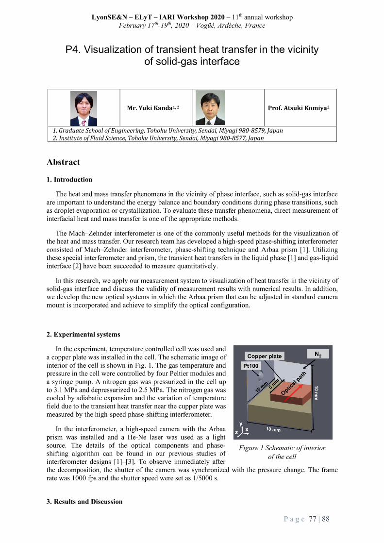
LyonSE&N – ELyT – IARI Workshop 2020 – 11th annual workshop February 17th-19th, 2020 – Vogüé, Ardèche, France
P a g e 77 | 88
P4. Visualization of transient heat transfer in the vicinity of solid-gas interface
Mr.YukiKanda1,2
Prof.AtsukiKomiya2
1.GraduateSchoolofEngineering,TohokuUniversity,Sendai,Miyagi980-8579,Japan2.InstituteofFluidScience,TohokuUniversity,Sendai,Miyagi980-8577,Japan
Abstract 1. Introduction
The heat and mass transfer phenomena in the vicinity of phase interface, such as solid-gas interface are important to understand the energy balance and boundary conditions during phase transitions, such as droplet evaporation or crystallization. To evaluate these transfer phenomena, direct measurement of interfacial heat and mass transfer is one of the appropriate methods.
The Mach–Zehnder interferometer is one of the commonly useful methods for the visualization of the heat and mass transfer. Our research team has developed a high-speed phase-shifting interferometer consisted of Mach–Zehnder interferometer, phase-shifting technique and Arbaa prism [1]. Utilizing these special interferometer and prism, the transient heat transfers in the liquid phase [1] and gas-liquid interface [2] have been succeeded to measure quantitatively.
In this research, we apply our measurement system to visualization of heat transfer in the vicinity of solid-gas interface and discuss the validity of measurement results with numerical results. In addition, we develop the new optical systems in which the Arbaa prism that can be adjusted in standard camera mount is incorporated and achieve to simplify the optical configuration.
2. Experimental systems
In the experiment, temperature controlled cell was used and a copper plate was installed in the cell. The schematic image of interior of the cell is shown in Fig. 1. The gas temperature and pressure in the cell were controlled by four Peltier modules and a syringe pump. A nitrogen gas was pressurized in the cell up to 3.1 MPa and depressurized to 2.5 MPa. The nitrogen gas was cooled by adiabatic expansion and the variation of temperature field due to the transient heat transfer near the cupper plate was measured by the high-speed phase-shifting interferometer.
In the interferometer, a high-speed camera with the Arbaa prism was installed and a He-Ne laser was used as a light source. The details of the optical components and phase-shifting algorithm can be found in our previous studies of interferometer designs [1]–[3]. To observe immediately after the decomposition, the shutter of the camera was synchronized with the pressure change. The frame rate was 1000 fps and the shutter speed were set as 1/5000 s.
3. Results and Discussion
Figure 1 Schematic of interior of the cell

LyonSE&N – ELyT – IARI Workshop 2020 – 11th annual workshop February 17th-19th, 2020 – Vogüé, Ardèche, France
P a g e 78 | 88
The phase shifted data in the vicinity of the solid-gas interface measured by the interferometer is shown in Fig. 2(a). The time shown in Fig. 2(a) is set to 0.00 s immediately after the depressurization. In this measurement, interference fringes variation was observed near the interface immediately after depressurization. These fringes change were caused by the density difference due to the temperature difference between the solid and gas phase. Therefore, the density variation due to the transient heat transfer near the interface was succeeded to measure.
Figure 2 Schematics of (a) sequential phase-shifted data after depressurization and (b) distribution of optical path length difference near the interface with numerical simulation.
Comparison of the distribution of optical path length difference, which is the apparent density distribution, near the interface at 0.1 s after depressurization obtained by the measurement images with the numerical simulation results is shown in Fig. 2(b). The temporal and spatial resolutions were 1 ms and 4 µm/pixel, respectively. In the numerical simulation, two-dimensional calculation for heat transfer in the gas phase by conduction was conducted with finite element methods by COMSOL Multiphysics Version 5.4. The adiabatic expansion effect was considered as pressure work according to the experimental pressure variations. As a result of the comparison, the experimental results showed a same tendency with the numerical result, however difference with the numerical results was also confirmed. These difference was estimated to be caused by the effects of convection and the numerical error by three-dimensional effects, which were not considered in this analysis. However, it was confirmed that our proposed system can measure temperature difference variation near the interface with high spatial and temporal resolutions although it is affected by the convection or geometric error.
References:
[1] E. Shoji, A. Komiya, J. Okajima, H. Kawamura, S. Maruyama, Applied Optics 54 (20) (2015) 6297–6304. [2] Y. Kanda, E. Shoji, L. Chen, J. Okajima, A. Komiya, S. Maruyama, International Communications in Heat and Mass
Transfer 89 (2017) 57–63. [3] Y. Kanda, H. Komatsu, J. Okajima, S. Maruyama, A. Komiya, International Journal of Heat and Mass Transfer 149 (2020)
(https://doi.org/10.1016/j.ijheatmasstransfer.2019.119191).

LyonSE&N – ELyT – IARI Workshop 2020 – 11th annual workshop February 17th-19th, 2020 – Vogüé, Ardèche, France
P a g e 79 | 88
P5. Mechanical behavior of hydrated PFSA membranes at nanoscale: from elasticity to rupture.
ELyTGlobal
Energy
Molecular simulations
Dr.WilliamGonçalves
Dr.TakuyaMabuchi
Prof.TakashiTokumasu
Abstract Becauseoftheiremissionsfreeofcarbondioxyde,polymerelectrolytefuelcells(PEFCs)areofgreat interest for the production of eco-friendly energy. The transport of the ionic chargesbetween the electrodes of the fuel cell is ensuredby a hydrated polymermembrane such asperfluorosulfonicacid(PFSA)membrane.Thedurabilityofthefuelcellisfurtherlimitedbythechemicalandmechanicaldegradationofthepolymermembraneafteroperatingcycles.Ourworkfocuses on studying the mechanical behavior of PFSA membrane at the nanoscale. Theunderstandingoftherelationshipbetweenstructureandmechanicalpropertiesisessentialtoimprovetheresistanceofthemembraneagainstmechanicaldegradation.
MolecularDynamics(MD)simulationsareperformedusingaCoarse-GrainedmodeltogeneratesamplesofPFSAmembranes.TheresultsofelasticmodulusforNafion,themosttypicalPFSAmembrane,areingoodagreementwiththeexperimentalvalues.Furthermechanicaltestsareperformed on PFSA membranes with different polymer structures. The results uncover anincreaseoftheelasticmodulusofNafionmembraneasitsEquivalentWeight(EW)decreases.Adetailed characterization of the nanostructures (structure factor, cluster size distribution,thickness of water network, radial distribution functions) is computed to understand thestructuralmodificationsimpliedbytheEWvariation.AnewdesignforthepolymerstructureisproposedtooptimizetheelasticpropertiesofthePFSAmembrane.
LyonSE&N – ELyT – IARI Workshop 2020 – 11th annual workshop February 17th-19th, 2020 – Vogüé, Ardèche, France
P a g e 80 | 88
P6. Investigation of Intravascular Endoscope Efficacy in Visualization through both Numerical and Experimental
Approaches
ELyTGlobal
HeathModeling&Simulation
YujieLi
InstituteofFluidScience,TohokuUniversity
KoheiMitsuzukaGraduateSchoolofBiomedicalEngineering,TohokuUniversity
SimonTupin
InstituteofFluidScience,TohokuUniversity
ToshioNakayamaNationalInstituteofTechnology,TsuruokaCollege
MakotoOhta
InstituteofFluidScience,TohokuUniversity
Abstract As blood vessels carry blood from heart throughout the body, any disease in this system may lead to tissues not getting enough blood, a condition called ischemia, which may result in other serious dangerous life-killing vascular diseases, such as stroke, carotid artery disease (CAD), etc.[1-3].
Through technology advancements and the introduction of new methodologies, endoscopic intravascular visualization is becoming more interesting as a diagnostic tool[4-5]. Intravascular imaging could be used to identify conditions that lead to strokes, aneurysm and embolism. In vivo imaging of the arteries could additionally help to find calcifications, plaques, thrombus and also to assess the placement of stents[4]. Identification of intraluminal appearances of calcified plaques allows more accurate assessment of coronary stenosis by detecting superficial and deep calcified plaques[6]. Thus, intravascular endoscope plays an important role in the clinical decision-making process and provide therapy relevant information[4].
This study aims to develop an endoscopy system that can realize the visualization of inner-
LyonSE&N – ELyT – IARI Workshop 2020 – 11th annual workshop February 17th-19th, 2020 – Vogüé, Ardèche, France
P a g e 81 | 88
arterial appearance without blocking off blood flow. Flush of dextran is selected to be injected into the artery to flow against the blood. To create a clear view in front of the endoscope camera, the flush is expected to strongly spread onto the inner-arterial wall instead of only flow in the lumen center, while retaining the flush recirculation around the camera.
According to fluid dynamics, flow pattern is mainly affected by the inflow rate, inner-arterial flow resistance and the fluid channel morphology. Therefore, this study aims to (1) establish a series of endoscope models with different catheter morphologies, (2) investigate the flow pattern of the injected flush against blood using both numerical and experimental approaches - from observations of CFD and PIV results, and (3) look for catheter morphology and flush flowrate setting that could most effectively spread the flush onto the arterial wall.
For brevity, this study is proposed to optimize the design of endoscope, by guiding the flush spreading out of the catheter impinging onto the target of observation (normally the blood vessel wall), so as to help clinicians to get a clear view of intravascular lesions, thus improving assessment of arterial disease.
References
[1] J. Liu et al. Vascular remodeling after ischemic stroke: Mechanisms and therapeutic potentials. Prog. Neurobiol., vol. 115, pp. 138–156, Apr. 2014, doi: 10.1016/j.pneurobio.2013.11.004.
[2] Q. Li et al. Cerebral small vessel disease. Cell Transplant., vol. 27, no. 12, pp. 1711–1722, Dec. 2018, doi: 10.1177/0963689718795148.
[3] R. Hajar. Risk factors for coronary artery disease: historical perspectives. Heart Views. 2017;18(3):109–114. doi:10.4103/HEARTVIEWS.HEARTVIEWS_106_17.
[4] A. Boese et al. Intravascular endoscopy improvement through narrow-band imaging. Int. J. Comput. Assist. Radiol. Surg., vol. 12, no. 11, pp. 2015–2021, Nov. 2017, doi: 10.1007/s11548-017-1579-4.
[5] T. Yamakoshi et al. A novel in vivo technique for endoscopic visualization of aortic valve motion and inner wall of large arteries for immediate postoperative direct observation. Trends Med., vol. 18, no. 4, 2018, doi: 10.15761/TiM.1000151.
[6] L. Xu and Z. Sun. Virtual intravascular endoscopy visualization of calcified coronary plaques: a novel approach of identifying plaque features for more accurate assessment of coronary lumen stenosis. Medicine (Baltimore), vol. 94, no. 17, p. e805, May 2015, doi: 10.1097/MD.0000000000000805.

LyonSE&N – ELyT – IARI Workshop 2020 – 11th annual workshop February 17th-19th, 2020 – Vogüé, Ardèche, France
P a g e 82 | 88
P7. Nano Scale Characterization on the Electrostrictive behavior of Amorphous poly(tetramethylene oxide) Elastomer
ELyTGlobalTEmPuRA18
EnergyModeling&Simulation
AiSuzuki,MasayukiMiyano,RyujiMiura,DiguetGildas,JeanYvesCaville,GaelSebald
Abstract Electroactive polymers are versatile materials capable of substantial changes in size or
shape. They are flexible, lightweight, eco-friendly, and easy to cut into desirable shape. The electroactive polymers include electrostrictive and dielectric elastomers, such as
silicone, acrylic, polyurethane, etc. So far, they have been demonstrated to be potentially useful due to their large actuation strains together with a high energy density [1]. Some of polyurethanes, known to exhibit a rather strong electroactivity, are block co-polymers with hard segments and soft segments. Soft segments consist of poly(tetramethylene oxide) (PTMO), which have ether bond, -(CH2)4O)- in their repeat units, as shown in Fig. 1. We performed the atomistic simulation of the amorphous PTMO and compare its strain as a function of the magnitude of applied electric field, aiming to reveal how the microstructure of PTMO influence the electrostriction properties when they are electrically polarized by the application of a homogeneous electric field.
The thermodynamics of the elastomers and the chemical reactions involving electron transfers can be quantified by the tight-binding based accelerated quantum chemical calculation program [2] coupled with a molecular dynamics method. Fig. 1 shows the atomic configuration of amorphous PTMO and the elasticity of amorphous PTMO and its potential gradient under the applied electric field is – 1.0 V/nm (left) and 1.0 V/nm (right). Here, we assume that the 3 axes are equivalent considering the amorphous phase due to small anisotropy in amorphous condition. A periodical unit cell for a amorphous PTMO atomic structure is shown in Fig. 1, where x = 2.51 nm, y = 2.77 nm, z = 2.75 nm, and all angles equal 90°. The amorphous chemical composition is C480H972O120 which consists of six C80H162O20 PTMO independent single chains, which consists of repeated -(CH2)4O)4- chains.
We obtained the potential gradient in amorphous PTMO through the electronic distribution of the PTMO elastomer calculated by a quantum calculation and molecular dynamics method. Upper parts of Fig. 1 show the potential gradient in the amorphous PTMO under the applied voltage, -1.0 V/nm and + 1.0 V/nm for z direction. The negative potential gradient was emerged for E= -1.0 V/nm, and positive potential gradient was emerged for E = +1.0 V/nm. Electrostriction is an electromechanical coupling behavior with the strain proportional to the
square of the applied electric field. Electrostriction allows a soft material to achieve larger strain at high applied fields than does piezoelectricity. The uniaxial stain is obtained by following equation [3],
s = (actuated length – unactuated length) / unactuated length
18TheoryforElectrostrictionofPolymeRicActuator
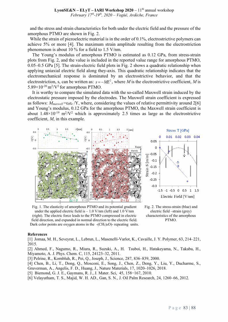
LyonSE&N – ELyT – IARI Workshop 2020 – 11th annual workshop February 17th-19th, 2020 – Vogüé, Ardèche, France
P a g e 83 | 88
and the stress and strain characteristics for both under the electric field and the pressure of the amorphous PTMO are shown in Fig. 2. While the strain of piezoelectric material is in the order of 0.1%, electrostrictive polymers can
achieve 5% or more [4]. The maximum strain amplitude resulting from the electrostriction phenomenon is about 10 % for a field to 1.5 V/nm.
The Young’s modulus of amorphous PTMO is estimated as 0.12 GPa, from stress-strain plots from Fig. 2, and the value is included in the reported value range for amorphous PTMO, 0.05–0.5 GPa [5]. The strain-electric field plots in Fig. 2 shows a quadratic relationship when applying uniaxial electric field along they-axis. This quadratic relationship indicates that the electromechanical response is dominated by an electrostrictive behavior, and that the electrostriction, s, can be written as: , where M is the electrostrictive coefficient, M is 5.89×10⁻²⁰ m2/V2 for amorphous PTMO.
It is worthy to compare the simulated data with the so-called Maxwell strain induced by the electrostatic pressure imposed by the electrodes. The Maxwell strain coefficient is expressed as follows: Mmaxwell =ε0εr /Y, where, considering the values of relative permittivity around 2[6] and Young’s modulus, 0.12 GPa for the amorphous PTMO, the Maxwell strain coefficient is about 1.48×10⁻¹⁹ m2/V2 which is approximately 2.5 times as large as the electrostrictive coefficient, M, in this example.
Fig. 1. The elasticity of amorphous PTMO and its potential gradient under the applied electric field is – 1.0 V/nm (left) and 1.0 V/nm
(right). The electric force leads to the PTMO compressed in electric field direction, and expanded in normal direction to the electric field.
Dark color points are oxygen atoms in the -(CH2)4O)- repeating units.
Fig. 2. The stress-strain (blue) and electric field –strain (grey)
characteristics of the amorphous PTMO.
References [1] Jomaa, M. H., Seveyrat, L., Lebrun, L., Masenelli-Varlot, K., Cavaille, J. Y. Polymer, 63, 214–221, 2015. [2] Ahmed, F., Nagumo, R., Miura, R., Suzuki, A., H. Tsuboi, H., Hatakeyama, N., Takaba, H., Miyamoto, A. J. Phys. Chem. C, 115, 24123–32, 2011. [3] Pelrine, R., Kornbluh, R., Pei, Q., Joseph, J., Science, 287, 836–839, 2000. [4] Chen, B., Li, T., Dong, Q., Mosconi, E., Song, J., Chen, Z., Deng, Y., Liu, Y., Ducharme, S., Gruverman, A., Angelis, F. D., Huang, J., Nature Materials, 17, 1020–1026, 2018. [5] Biemond, G. J. E., Gaymans, R. J., J. Mater. Sci, 45, 158−167, 2010. [6] Velayutham, T. S., Majid, W. H. AD., Gan, S. N., J. Oil Palm Research, 24, 1260–66, 2012.
2s ME= -

LyonSE&N – ELyT – IARI Workshop 2020 – 11th annual workshop February 17th-19th, 2020 – Vogüé, Ardèche, France
P a g e 84 | 88
P8. Prediction of thermal and mechanical properties of Silica Aerogel using atomic scale simulations
ELyTGlobalSilicaGelSim19
Theme: Energy
Scientific topic: Modelisation/Simulation
Prof.TakashiTokumasu
Prof.PatriceChantrenne
Aikaterini Kiourtzidou Master Student
Abstract Molecular Dynamics is an interesting tool to investigate physical phenomena in order to understand systems behaviors at the macroscopic scale. The presentation will focus on the MD simulation to study heat transfer in silica aerogels. This material is used for high performance thermal insulation. Its thermal conductivity is really low thanks to a high nanoporosity (more than 90% of porosity), which also explain the poor mechanical properties. Up to now, pure silica aerogel were simulated to study the thermal and mechanical properties of small nanograin which size is (100 nm)3. The properties are used for larger scale simulations. Actually, aerogel are not only made of pure silica. The surfaces of the porous material have some molecules that come from the process to increase the life duration (surfactant). To simulate these ‘real’ materials, reactive interatomic potentials have to be used. With these potentials, the computational time do not allow simulating nano-porous nano-particles. Thus, the goal of the study is to simulate silica nanowires with surfactant and predict their thermal properties. This work is realized within the framework of the internship of Aikaterini Kiourtzidou.
19predictionofthermalandmechanicalpropertiesofSilicaAeroGelusingatomicscaleSimulations

LyonSE&N – ELyT – IARI Workshop 2020 – 11th annual workshop February 17th-19th, 2020 – Vogüé, Ardèche, France
P a g e 85 | 88
P9. High Frequency Eddy Current Testing for Fiber Waviness, Misorientation, Hardening Degree in Carbon Fiber Reinforced
Plastic
ELyT Global
HiroyukiKosukegawaInstituteofFluidScience,TU
MitsuoHashimotoInstituteofFluidScience,TU
TetsuyaUchimotoInstituteofFluidScience,TUELyTMaXUMI3757,CNRS–UdL–TU
ToshiyukiTakagiInstituteofFluidScience,TUELyTMaXUMI3757,CNRS–UdL–TU
Abstract
Carbon fiber reinforced plastics (CFRPs) have been increasingly employed for structural materials in various industries these days. However, the development of nondestructive testing (NDT) technique for CFRPs is still not enough. In particular, “fiber waviness” “misorientation” and “resin hardening degree” are representative defects that largely affect mechanical properties of the product and cannot be inspected by conventional NDT technique. We introduce electromagnetic nondestructive technique with high frequency eddy current to inspect and evaluate these defects.
In this paper, we adopt three types of directional eddy current differential probes for NDT of fiber waviness and misorientation: (i) circular driving (CirD), (ii) symmetrical driving (SymD), and (iii) uniform driving (UniD). CirD probe generates locally directional eddy current near pickup coils. UniD generates directional and widely uniform eddy currents.
The detectability of waviness and misorientation are evaluated with three probes above. CirD probe shows fairly good performance. UniD probe shows the highest performance on both defects. These capacities of UniD probe are effective to assess the quality in mechanical properties of the CFRP products. We conclude that ECT with directional eddy current can be a powerful technique to evaluate fiber waviness and misalignment and useful for quality assurance of CFRP products.
Additionally, we attempt to evaluate the hardening degree of epoxy resin of CFRP by using high frequency eddy current. With the increase of curing progress, the coil impedance is reduced. This tendency follows the results of differential scanning calorimetry and chemiluminescence method. The physical phenomena can be explained by the decrease in the dielectric permittivity associated with the upgrading of the amine groups in epoxy.
These results mean that high frequency eddy current testing has possibility for NDT of fiber waviness, misorientation and hardening degree of matrix resin in CFRP.

LyonSE&N – ELyT – IARI Workshop 2020 – 11th annual workshop February 17th-19th, 2020 – Vogüé, Ardèche, France
P a g e 86 | 88
P10. Microstructure study of Fe-based BMG reinforced with Al2O3 obtained by Spark Plasma Sintering.
ELyTGlobalNewProject
Theme: Material Science
Scientific topic: Anticorrosion
Dr.LilianaZarazúa-Villalobos
Dr.NicolasMary
Prof.KazuhiroOgawa
Prof.HidemiKato
Abstract Metallic glass and alloys are new materials of great interest because they exhibit electronic and optical properties similar to ordinary metals but without the typical crystal defects such as vacancies, dislocations or grain boundaries. The lack of defects positively impacts their chemical, physical and mechanical properties. The bulk metal glass with a Fe48Cr15Mo14C15B6Y2 composition, which will be of interest here, is specially well known for exceptional anticorrosive properties.
In this experimental study, the alloy is made by a convection oven under argon atmosphere and the metal glass powder is obtained by high pressure spray atomization. After spraying, the powder is sieved until 43 µm mesh. The final powder is composed of a mix of spherical and long shaped particles with an average particle size of 25.7 µm.
The powder is processed by SPS at temperatures below the glass transition temperature using uniaxial forces between 50 to 400 Mpa. The effect of the sintering cycle on the crystallinity and the densification is investigated. The sintered samples reached a high density of 99 % while keeping their amorphous structure. Additionally, ceramic particles (Al2O3) are added to the powder and mixed. The effect of the size and the weight percentage of the ceramic particles on the final microstructure is further characterized using Scanning Electron Microscope (SEM), Archimedes density, X-ray diffraction and TEM.

LyonSE&N – ELyT – IARI Workshop 2020 – 11th annual workshop February 17th-19th, 2020 – Vogüé, Ardèche, France
P a g e 87 | 88
P11. Magnetic control for high chromium steel creep
ELyTGlobal
Theme: Electromagnetic NDT Scientific topic: Electromagnetic instrumentation
Gael Sebald
1ELyTMaX UMI 3757, CNRS-Université de Lyon-Tohoku University International Joint Unit, Tohoku University, Sendai, Japan
Tetsuya Uchimoto 1ELyTMaX UMI 3757, CNRS-Université de Lyon-Tohoku University International Joint Unit, Tohoku University, Sendai, Japan 2Institute for Fluid Science, Tohoku University, Sendai, Japan
Benjamin Ducharne
1Univ. Lyon, INSA-Lyon, LGEF EA682, F69621 Villeurbanne, France
Toshiyuki Takagi 1ELyTMaX UMI 3757, CNRS-Université de Lyon-Tohoku University International Joint Unit, Tohoku University, Sendai, Japan 2Institute for Fluid Science, Tohoku University, Sendai, Japan
Abstract Creepphenomenonisanimportantfeaturetoassessinhightemperatureapplications,
althoughthecorrelationswithmicrostructureandmagneticbehaviourremainunclear.In thisproject,12%Cr-Mo-W-Vcreeptestsamples(used inthermalpowerplants)areinvestigated using three electromagnetic inspection techniques.Magnetic parametersbased on the results are then evaluated in comparison to the microstructure.Additionally,amodified Jiles-Athertonmodelhasbeenusedtonumericallyreproduceexperimental results from Magnetic Incremental Permeability (MIP), MagneticBarkhausenNoise (MBN) and standardB(H)measurements. All the three techniquesexhibit different responses in understanding creep and the modelling parametersderived from the adapted Jiles-AthertonModel parameters are then correlated to themicrostructureinformation.Couplingbetweenthestressandmagneticfieldisthemainand important feature of the ferromagnetic materials consisting of various smallmagnetic domains in itsmicrostructure [1][2]. Conventional Eddy current testinghasbeenextensivelyusedfortheferromagneticmaterialscharacterizationbutwhenitcomestocreepdamagedetection,itbecomesdifficulttodistinguishbetweenthechangescausedbytheactualcreepdamageandfromthesignalsgeneratedbyothersourceslike,cracks,surface roughness, hardness etc. In this research three different electromagnetictechniquesareappliedtothe12differentsamplesfromthreedifferentcategorieswithdifferenttemperatureandstresstreatments.MagneticIncrementalPermeability(MIP)isusedtoinvestigatesamplesasitishighlysensitivetostress.Ontheotherhand,MagneticBarkhausenNoisebeingsensitivetothemechanicalchangesinthematerials,isalsousedto analyse the samples in addition to standard B(H) curve measurements. Finally,

LyonSE&N – ELyT – IARI Workshop 2020 – 11th annual workshop February 17th-19th, 2020 – Vogüé, Ardèche, France
P a g e 88 | 88
ferromagnetic hysteresismodels such as dry friction quasi staticmodel [3], Preisachmodel [4], Jiles-Athertonmodel [5],which are based onmagnetic inductionB versusapplied magnetic field strength H, are tested to get the simulated data based onexperiments. Having a physical interpretation, the J-A model [6] is chosen but it ismodified to derive modelling parameters which are then evaluated against themicrostructureof thetestsamples.Finally,experimentaldataobtainedusingdifferenttechniques applied to creep samples are presented, and the relevant ferromagneticmodel is given. Fig. 1(a) below shows evolution of one of the J-A parameters ‘K’ vs.Precipitationnumberfordifferentlytreatedsamples.Itisquiteevidentthattheenergyrequired(K)tobreakthepinningsiteislargerincaseofhighernumberofprecipitates.
Figure 1(a): Evolution of J-A parameter ‘K’ vs. Precipitations
Figure 1(b): Pearson correlation coefficient for evolution of ‘K’ vs. different
microstructural and mechanical parameters
After the determination of these parameters, Pearson correlation coefficient isevaluatedagainstdifferentmechanicalandmicrostructuralparametersasshowninFig.1(b).
References
[1] Schull P.J.; Non-destructive evaluation: theory, techniques and applications. New York. Marcel Dekker, Inc., 2002. [2] B. Ducharne and al., “Phenomenological model of Barkhausen noise under mechanical and magnetic excitations”, IEEE Trans. on. Mag, vol. 99, pp. 1-6, 2018. [3] B. Ducharne and al., “Low frequency modelling of hysteresis behaviour and dielectric permittivity in ferroelectric ceramics under electric field”, Journal of Physics D: Applied Physics, vol. 40, iss. 2, pp. 551-555, 2007. [4] B. Zhang and al., “Preisach’s model extended with dynamic fractional derivation contribution”, IEEE Trans. on. Mag, vol. 54 iss. 3, 2017. [5] B. Zhang and al., “Dynamic magnetic scalar hysteresis lump model, based on JilesAtherton quasi-static hysteresis model extended with dynamic fractional derivative contribution”, IEEE Trans. on. Mag, iss. 99, 2018. [6] D. C. Jiles and D. L. Atherton, J. Magn. Magn. Mater., vol. 61, no. 1–2, pp. 48–60, Sep. 1986.