Embed Size (px)
Citation preview
1
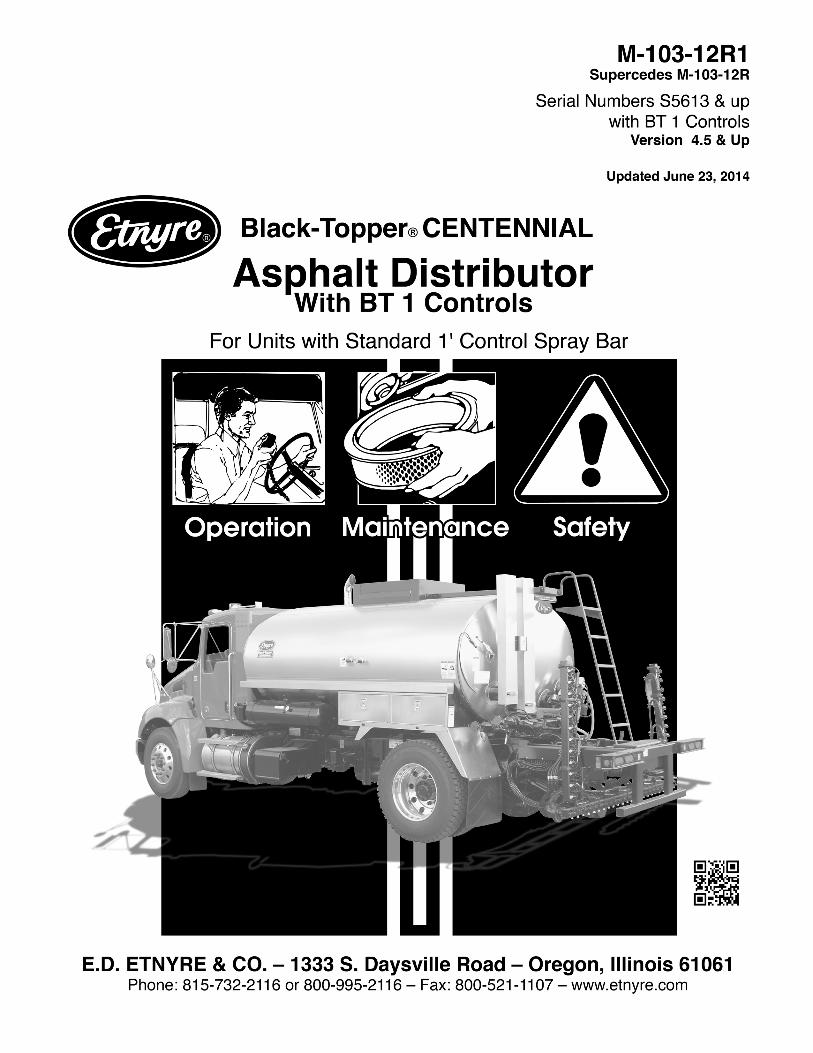
M-103-12R1Black-Topper Centennial Operation, Maintenance, and Safety Manual
BLACK-TOPPER Distributor with Standard Spraybar and BT-1 Controls
Version 4.5 & up
WARRANTYE. D. Etnyre & Co. warrants to the original Purchaser, its new product to be free from defects in material and workmanship for a period of twelve (12) months after date of delivery to original Purchaser. The obligation of the Company is limited to repairing or replacing any defective part returned to the Company and will not be responsible for consequential damages or any further loss by reason of such defect.The company excludes all implied warranties of merchantability and fitness for a particular purpose. There are no warranties, express or implied, which extend beyond the description of the goods contained in this contract.This warranty does not obligate the Company to bear the cost of machine transportation in connection with the replacement or repair of defective parts, nor does it guarantee repair or replacement of any parts on which unauthorized repairs or alterations have been made or for components not manufactured by the Company except to the extent of the warranty given by the original Manufacturer.This warranty does not apply to:(1) Normal startup services, normal maintenance services or adjustments usually performed by the selling dealer, factory service representative or customer personnel.(2) Any product manufactured by E. D. Etnyre & Co. purchased or subjected to rental use.(3) Any product or part thereof which shows improper operation, improper maintenance, abuse, neglect, damage or modification after shipment from factory.(4) Any product or part thereof damaged or lost in shipment. Inspection for damage should be made before acceptance or signing any delivery documents releasing responsibility of the delivering carrier.This warranty and foregoing obligations are in lieu of all other obligations and liabilities including negligence and all warranties of merchantability or otherwise, express or implied in fact or by law.
WARNINGDo not use this machine for any operation that is not described in this manual.If you have any questions about operation of this machine, contact the Etnyre Service Department at 1-800-995-2116 or 1-815-732-2116.Operations that are not approved could cause serious injury or death.
WARNINGDiesel engine exhaust and some of its constituentsare known to the State of California to cause cancer, birth defects, and other reproductive harm.
Please note this warningand remember:
• Always start and operate the engine in a well ventilated area.
• If in an enclosed area, vent the exhaust to the outside.
• Do not modify or tamper with the exhaust system. Can cause serious injury or death.
Serial Number S5613 and up
Updated June 23, 2014

2
© Copyright 2010 E.D. Etnyre & Co.All brand names, trademarks and registeredtrademarks are the property of their respectiveowners. Information contained within thisdocument is subject to change without notice. Allrights reserved.
3
Table of ContentsSafety InstructionsWarning And Instruction Plates ..........................5General Safety Instructions ................................7Safety Precautions, Hazard Seriousness Level .7WARNINGS ........................................................8 Fluoroelastomer Handling ...............................8Foaming............................................................10Asphalt Institute ................................................10Introduction .....................................................11Reporting Safety Defects..................................11Component Location And Identification ............12Rear and Side Components .............................12Spray Bar Components ....................................13Hydraulic Tank Components .............................13Cab Control Panel ............................................14Rear Control Panel ...........................................16Preparing for Operation .................................19Setting Up the Computer ..................................19 First Screen ..................................................19 Second Screen .............................................19 Third Screen .................................................19 Fourth Screen ...............................................20 Fifth Screen ..................................................20 Sixth Screen .................................................20Engaging Pump on PTO Equipped Distributors .. 20 Manual Transmissions ..................................20 Automatic Transmissions ..............................20Spraying Operations .........................................21Setting the Digital Memory Presets ..................22Adjusting the Spray Bar Nozzle Angle ..............22Adjusting the Spray Bar Height ........................22Operation .........................................................23Tank Capacity ...................................................23Operation Screens............................................23First Operating Screen .....................................23Second Operating Screen ................................23Third Operating Screen ....................................24Information Messages ......................................24Loading .............................................................26 Loading Through the Manhole ......................26 Loading Through the Load Line Connections and Preliminary Checks...........27 Check Strainers ............................................27 Using the Measuring Stick ............................27 Loading Through the Load Line ....................28Circulating in the Tank ......................................30Circulating Product in the Bar ...........................32Spraying Through the Bar ................................34Hand Spraying ..................................................35
Spray Bar Suckback .........................................36Bar Suck Back Override ...................................38Handspray Suckback........................................39Flushing Operations .........................................40 Bar Flush (Auto) ...........................................40 Bar Flush (Manual) .......................................41 Enviro-Flush System (OPTIONAL).............. 42 Recycle Enviro-Flush................................... 43Unload Operations with External Pump............44Unload Operations with Distributor Pump ........46Transfer Operations ..........................................48Heating Product in Distributors ....................50 Heating with Propane Burners.......................50 Propane Requirements................................50 Manual Ignition Control................................51 Ignition and Out Fire Control .......................52 Thermostatic Control ...................................54 Heating with Fuel Oil Burners ........................55 Ignition and Out Fire Control .......................56 Thermostatic Control ...................................57Troubleshooting .............................................58Maintenance ....................................................60Gun Assembly ..................................................60Electrode Settings ............................................60Check Ignition Transformer Spark ....................61Fire Burners ......................................................61Replacing Speed Pickup ..................................61Servicing the Etnyre P-15 Pump ......................62 Vacuum Check .............................................62 Pump Disassembly And Inspection ..............62 Impeller Installation And Pump Assembly.....62General Fuel Data and Heating Terminology ...63 Fuel Data ......................................................63 Approximate Burner Fuel Consumption........63 Heating Terminology .....................................63Hydraulic Fluid Requirements ..........................64 General Information ......................................64 Hydraulic Fluid Requirements ......................64 Viscosity & Temperature Requirements .......64 Contamination Levels ...................................65Lubrication Chart ..............................................67Etnyre Spraybar Nozzles ..................................68Serial Number Plate Location ..........................69Decimal Equivalent Chart .................................69
4
List of Illustrations
Figure 1. Location of Warning and Instruction Plates. .................................... 5Figure 2. Rear and Side Component Identification....................................... 12Figure 3. Rear Component Identification. ..................................................... 12Figure 4 Spray Bar Component Identification.............................................. 13Figure 5. Hydraulic Tank Component Identification. ..................................... 13Figure 6. Cab Control Panel Components.................................................... 14Figure 7. Rear Control Panel Components. ................................................. 16Preparing for OperationFigure 8. Adjusting the Spray Bar Nozzles. .................................................. 22Figure 9. Adjusting the Spray Bar Height. .................................................... 22OperationFigure 11. Valve Positions for Loading Through the Manhole. ..................... 26Figure 12. Using the Measuring Stick........................................................... 27Figure 13. Valve Positions for Loading Through the Load Line. ................... 28Figure 14. Valve Positions for Circulating in the Tank. ................................. 30Figure 15. Valve Positions for Circulating in the Bar. .................................... 32Figure 16. Valve Positions for Spraying Through the Bar. ............................ 34Figure 17. Valve Positions for Handspray. .................................................... 35Figure 18. Valve Positions for Spray Bar Suck Back. ................................... 36Figure 19. Valve Postions for Flushing. ........................................................ 40Figure 20. Enviro-Flush Flow Diagram........................................................ 42Figure 21. Recirculating Flushing System Operation................................... 43Figure 22. Valve Positions for Unload with External Pump. ......................... 44Figure 23. Valve Positions for Unload with Distributor Pump. ...................... 46Figure 24. Valve Positions for Transfer. ........................................................ 48 Figure 25. Manual Ignition Control. .............................................................. 51Figure 26. Ignition and Out Fire Control. ...................................................... 52Figure 27. Fuel Oil Burner System. .............................................................. 56MaintenanceFigure 28. Gun Assembly. ............................................................................ 60Figure 29. Right Hand / Left Hand Electrodes .............................................. 60Figure 30. Electrode Setting. ........................................................................ 60Figure 31. Hydraulic Motor. .......................................................................... 61Figure 32. Etnyre Asphalt Pump. .................................................................. 62Figure 33. Fluid Cleanliness Chart. .............................................................. 65Figure 34. Serial Number Plate Location...................................................... 69
5
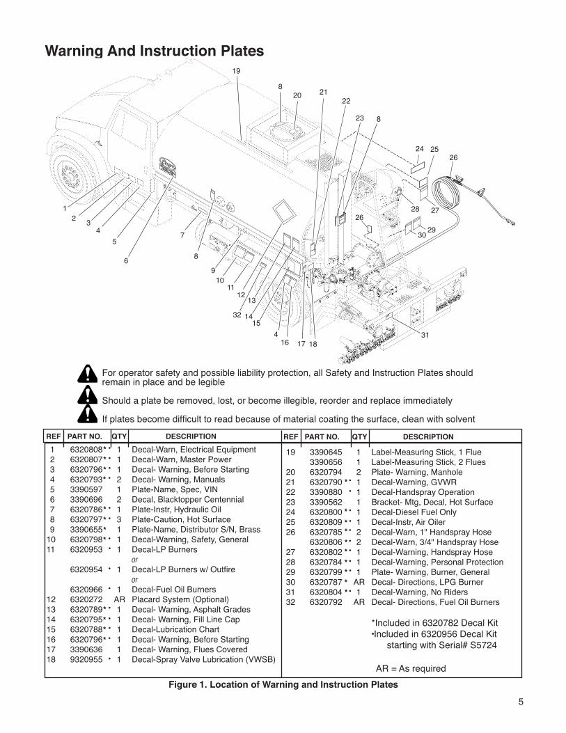
19 3390645 1 Label-Measuring Stick, 1 Flue 3390656 1 Label-Measuring Stick, 2 Flues 20 6320794 2 Plate- Warning, Manhole 21 6320790 1 Decal-Warning, GVWR 22 3390880 1 Decal-Handspray Operation 23 3390562 1 Bracket- Mtg, Decal, Hot Surface 24 6320800 1 Decal-Diesel Fuel Only 25 6320809 1 Decal-Instr, Air Oiler 26 6320785 2 Decal-Warn, 1" Handspray Hose 6320806 2 Decal-Warn, 3/4" Handspray Hose 27 6320802 1 Decal-Warning, Handspray Hose 28 6320784 1 Decal-Warning, Personal Protection 29 6320799 1 Plate- Warning, Burner, General 30 6320787 AR Decal- Directions, LPG Burner 31 6320804 1 Decal-Warning, No Riders32 6320792 AR Decal- Directions, Fuel Oil Burners *Included in 6320782 Decal Kit •Included in 6320956 Decal Kit starting with Serial# S5724
Warning And Instruction Plates
Figure 1. Location of Warning and Instruction Plates
For operator safety and possible liability protection, all Safety and Instruction Plates should remain in place and be legible
Should a plate be removed, lost, or become illegible, reorder and replace immediately
If plates become difficult to read because of material coating the surface, clean with solvent
20
12 3
4
4
57
8
910
11
32
16 17 18
12
15
13
14
8
8
19
20 2122
23
24 25
28 27
30 29
26
31
26
6
AR = As required
REF PART NO. QTY DESCRIPTION REF PART NO. QTY DESCRIPTION 1 6320808 1 Decal-Warn, Electrical Equipment 2 6320807 1 Decal-Warn, Master Power 3 6320796 1 Decal- Warning, Before Starting 4 6320793 2 Decal- Warning, Manuals 5 3390597 1 Plate-Name, Spec, VIN 6 3390696 2 Decal, Blacktopper Centennial 7 6320786 1 Plate-Instr, Hydraulic Oil 8 6320797 3 Plate-Caution, Hot Surface 9 3390655 1 Plate-Name, Distributor S/N, Brass10 6320798 1 Decal-Warning, Safety, General 11 6320953 1 Decal-LP Burners or 6320954 1 Decal-LP Burners w/ Outfire or 6320966 1 Decal-Fuel Oil Burners12 6320272 AR Placard System (Optional)13 6320789 1 Decal- Warning, Asphalt Grades14 6320795 1 Decal- Warning, Fill Line Cap15 6320788 1 Decal-Lubrication Chart16 6320796 1 Decal- Warning, Before Starting17 3390636 1 Decal- Warning, Flues Covered18 9320955 1 Decal-Spray Valve Lubrication (VWSB)
••
•
•
••
•
•
••
•••
••
•
•
•
•
•
•
•
•
•
*
•
**
*
*
***
**
**
**
**
*
*
*
**
*
6
NOTICEThe handling of Cationic Emulsions (CRS-2, CMS-2, CSS-1 and CSS) may create an environment within the Asphalt Distributor that can be corrosive to carbon steel and cast iron.
• Cationic Emulsions are widely used within the industry.• Cationic Emulsion is manufactured with asphalt, water, emulsifiers and
hydrochloric acid. The chemistry of individual emulsions varies in asphalt content and Ph levels.
• Tanks and spray mechanisms used with Cationic emulsions may experience corrosion
• It is believed the chemistry of the emulsion - specifically the residual fumes promote the corrosion
• Etnyre Distributors are compatible with Cationic Emulsions provided that certain precautions are taken.
• Prior to placing a distributor in to service with Cationic Emulsion, it should be loaded with an AC or MC type material to develop a protective coating.
• Periodic inspection of the tank and spray system should be preformed in the normal course of operation.
• It is recommended that distributors used in Cationic service be flushed periodically and at the end of the season with an AC, MC or cutback to remove the corrosive materials and to provide a protective coating.
• Increasing the quantity of flushing material during daily suck back and cleanout operations will also help to minimize corrosion damage.
• Dilution is the solution. • Additional information can be acquired from your Emulsion supplier as well as
the Asphalt Institute or the Asphalt Emulsion Manufactures Association.
WARNINGTake extra care and follow recommended procedures when alternating asphalt materials especially when loading hot product, over 212 degrees Fahrenheit (100 degrees Celsius), on to a tank and system previously in Emulsion service.
7
The operation of a bituminous distributor normally requires handling of liquid products at elevated temperature. Also, these liquids may be of a volatile nature. A heating system is supplied to raise or maintain the product temperature, and these systems use highly combustible fuels. As with any type of construction equipment, there are certain hazards associated with careless or improper operation.Safety warnings have been provided to call attention to any potentially hazardous situation that may cause property damage, personal injury or death to the operator or bystanders. These safety warnings will be shown at various times throughout this manual, as they are applicable to the subject being presented. These safety warnings are identified by the following warning symbols:
Safety Precautions, Hazard Seriousness LevelYou will find safety information boxes throughout this manual. These boxes contain information alerting you to situations or actions to avoid.Signal words (DANGER, WARNING, and CAUTION) are used to identify levels of hazard seriousness. Their selection is based on the likely consequence of human interaction with a hazard. Definitions of hazard levels are as follows.
DANGER - Immediate hazards which will result in severe personal injury or death.
WARNING - Hazards or unsafe practices which could result in severe personal injury or death.
CAUTION - Hazards or unsafe practices which could result in minor personal injury or product or property damage.
All of these warnings are listed below and they also appear throughout the manual. In addition to these, you will find notes throughout the manual.
NOTE - A note provides general information that the operator should be aware of when performing an operation.
General Safety Instructions
DANGERTo avoid an extreme fire hazard or explosion, NEVER use gasoline as fuel in diesel or fuel oil burners.
WARNINGA fully charged dry chemical type fire extinguisher must be within easy reach whenever the burners are operating or there is an open flame near the Distributor. The minimum capacity of the fire extinguisher should be 10 pounds.
Please Note This Warning and Remember:
• Always start and operate the engine in a well ventilated area.• If in an enclosed area, vent the exhaust to the outside.• Do not modify or tamper with the exhaust system.
8
WARNINGA fully charged dry chemical type fire extinguisher must be within easy reach whenever the burners are operating or there is an open flame near the Distributor. The minimum capacity of the fire extinguisher should be 10 pounds.
Fluoroelastomer HandlingSome O-rings and seals used in this vehicle are made from fluoroelastomers, When used under design conditions, fluoroelastomers do not require special handling. However, when fluoroelastomers are heated to temperatures beyond their design temperature (around 600º Fahrenheit), decomposition may occur with the formation of hydrofluoric acid. Hydrofluoric acid can be extremely corrosive to human tissue if not handled properly.A degraded seal may appear as a charred or black sticky mass, Do not touch either the seal or the surrounding equipment without wearing neoprene or PVC gloves if degradation is suspected. Wash parts and equipment with 10% lime water (calcium hydroxide solution) to neutralize any hydrofluoric acid.If contact with the skin occurs, wash the affected areas immediately with water. Then rub a 2.5 calcium gluconate gel into the skin until there is no further irritation, while seeking prompt medical attention.Note to Physicians: For advice or treatment of HF burns, call the DuPont Medical Emergency number, 1-800-441-3637.
To prevent an explosion or fire hazard:• Position the unit broadside to the wind to
prevent volatile fumes from drifting toward the burners.
• Do not operate the burners if the tank is damaged or leaking.
• Ensure that the burners are extinguished before removing any material from the tank in any manner. Liquid petroleum (LP) burners can support a flame for several minutes after the fuel supply is turned off.
To prevent an explosion or fire hazard:• Do not operate the burners when the vehicle
is unattended, when the vehicle is in motion, or with the vehicle in a confined area.
• When the burners go out, shut off the fuel supply to both burners and allow the flues to ventilate for at least 3 minutes before re-lighting the burners.
• Do not heat the material beyond the manufacturer’s recommended temperature.
• Keep burning cigarettes or other sources of combustion away from manholes and overflow vents.
• Keep area free of all sources of combustion when spraying.
• Check the tank vent to insure that it is free from obstruction before lighting the burners.
• Eliminate sparks from engine exhaust.• Do not operate the burners with the manhole
open or open the manhole while the burners are in operation.
• Flues must be covered by a minimum 6 inches of material (bitumen) when burners are in operation.
To prevent possible hand or facial burns:• Always light the inside burner first. Do not reach across a lit burner to light or re-light
the inside burner. Shut off the outside burner before lighting the inside burner.
To prevent possible burns:• Always use a torch to light the burners.
Never attempt to light the burners using a match or pocket lighter.
• Always wear insulated gloves when handling spray bar sections or hoses.
• Always wear eye protection, face shield, long sleeve shirt, insulated gloves, boots, and long pants outside the boots when working around the Distributor.
• Use extreme caution when using a torch to heat the pump. Asphalt accumulated around the pump may ignite when heating the pump with a torch.
WARNINGS
9
WARNINGSTo prevent possible burns from leaking material:• Be sure all pipe, cap and hose connections
are secure before opening valves, or beginning any operation.
To prevent possible burns from hot asphalt spray:• Do not stand, or allow anyone to stand,
where accidental opening of a valve may cause contact with hot asphalt.
To prevent possible burns from foaming or violent eruption:• Do not load tank with material temperature
over 200º F if water or condensation is present in tank, or if emulsion was used in the previous load.
• Do not heat material over 200º F if moisture or emulsified material is present in tank.
To prevent burns from hot asphalt when hand spraying:• Hold the handspray gun in proper position and watch for other people.To prevent possible burns to operators or bystanders, or possible equipment damage:• Do not start any operation if any control
settings are unknown.To prevent severe injury from becoming entangled in machinery:• Stand clear of rotating drives.To prevent possible injury:• Always open the manhole cover slowly.
Pressure build up in the tank may cause the cover to burst open.
To prevent possible fire hazards, burns or falls:• Keep the unit clean for safe operation.To prevent possible burns from material overflow:• Allow sufficient space in the tank for
expansion of the material when heating• Before removing the fill line cap, make
certain that the asphalt pump is turning and the tank valve is closed.
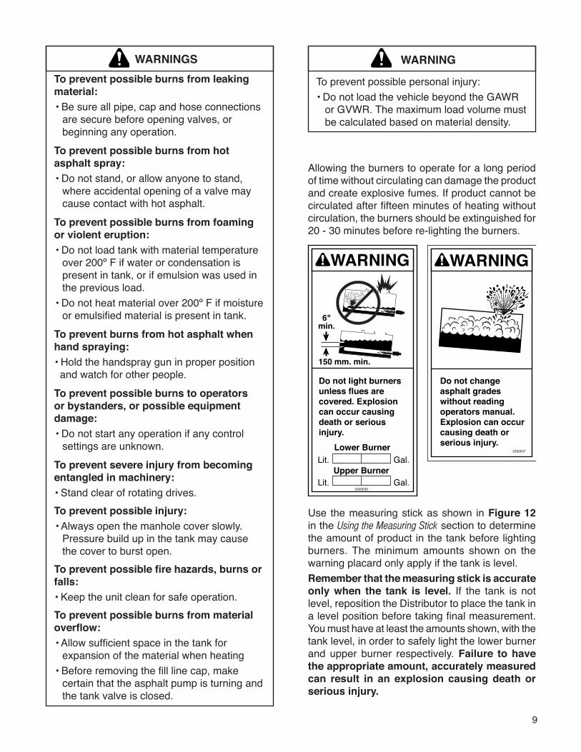
WARNING
To prevent possible personal injury:• Do not load the vehicle beyond the GAWR or GVWR. The maximum load volume must be calculated based on material density.
Allowing the burners to operate for a long period of time without circulating can damage the product and create explosive fumes. If product cannot be circulated after fifteen minutes of heating without circulation, the burners should be extinguished for 20 - 30 minutes before re-lighting the burners.
Use the measuring stick as shown in Figure 12 in the Using the Measuring Stick section to determine the amount of product in the tank before lighting burners. The minimum amounts shown on the warning placard only apply if the tank is level.Remember that the measuring stick is accurate only when the tank is level. If the tank is not level, reposition the Distributor to place the tank in a level position before taking final measurement. You must have at least the amounts shown, with the tank level, in order to safely light the lower burner and upper burner respectively. Failure to have the appropriate amount, accurately measured can result in an explosion causing death or serious injury.
10
Foaming
WARNINGTo prevent possible burns from foaming or violent eruption:• Do not load tank with material temperature
over 200ºF if water or condensation is present in tank, or if emulsion was used in the previous load.
• Do not heat material over 200ºF if moisture or emulsified material is present in tank.
If the Distributor is to be filled with hot bitumen, proceed very cautiously. If there is any moisture in the tank, or if an emulsion product was the last load, foaming or eruption may occur.Dow-Corning DC-200 may be used to prevent foaming in Distr ibutors, Transports, and Maintenance Units.Mix the contents of one can (16 oz.) with one (1) gallon of diesel fuel or kerosene. Add one (1) oz. of this diluted mixture to each 1000 gallons of asphalt. The correct amount may be poured through the manhole. This will assist in reducing foaming, particularly if moisture is present or if an emulsified asphalt was used in a previous load.If foaming does not occur at the start of the loading operation, but you suspect that there may be moisture in the spray bar or circulating system, the loading operation should be stopped when the tank is no more than 25% full. The product should then be circulated through the spray bar at a rate of 80 to 100 GPM before continuing the loading operation.If foaming does occur, continue circulating until the foaming stops, and then suck back the product in the spray bar back into the tank before filling the tank the rest of the way.
Asphalt InstituteTo further increase awareness of the hazards associated with the operation of a bituminous distributor, and before beginning initial operation, the operator should also receive instruction by an authorized Etnyre dealer, or Etnyre representative.The Centennial Distributor is designed to handle a number of different products, such as ACs, cutbacks & emulsions.Knowledge of these liquid asphalts is required for safe operation of the Distributor. It is critical to know which product can be loaded after the previous product, and which products react with each other.The Asphalt Institute is a source of asphalt handling safety information. Asphalt Institute Research Park Drive PO Box 140052 Lexington, KY 40512-4052 606-288-4960
11
Your Etnyre Blacktopper Centennial Distributor is designed to give you many years of accurate, dependable, and economic service. The following instructions will enable you to receive the maximum performance from your Blacktopper Centennial Distributor.The Blacktopper Centennial Distributor’s controls are designed for simple operation. They require a minimum of training for proficient usage. The exclusive Etnyre circulating system is designed and built for handling all grades of bituminous materials efficiently.This manual is provided as a tool to aid personnel in the operation of the Etnyre Blacktopper Centennial Distributor in a safe and efficient manner. As with any type of construction equipment, there are certain hazards associated with improper or careless operation. The ability to read and understand the instructions in this manual should be a required qualification to become an operator. There are also functions that require a certain amount of physical strength to accomplish. Persons lacking the required strength may not only place themselves in jeopardy, but also others in the vicinity.This manual covers standard features and options for truck mounted units with computerized controllers only. If your unit is equipped with Basic Controls, please refer to Operation manual number M-102-99 or later. If your unit incorporates custom features, some of the information contained in this manual may not apply. If you have any questions regarding this manual or your unit, contact your Etnyre dealer or the E. D. Etnyre Service Department at 1-800-995-2116.
CAUTIONUnusually strong electromagnetic interference could cause the electronic controls on this equipment to temporarily malfunction. Test the effect of two way radios and similar equipment while operating in a safe area.
Introduction
Reporting Safety DefectsIf you believe that your vehicle has a defect which could cause a crash, or could cause injury or death, you should immediately inform the National Highway Traffic Safety Administration (NHTSA) in addition to notifying E. D. Etnyre & Co.If NHTSA receives similar complaints, it may open an investigation; and, if it finds that a safety defect exists in a group of vehicles, it may order a recall and remedy campaign. However, NHTSA cannot become involved in individual problems between you, your dealer, or E. D. Etnyre & Co.To contact NHTSA, you may either call the Auto Safety Hotline toll free at 1-800-424-9393 (or 336-0123 in the Washington, D.C. area) or write to NHTSA, U.S. Department of Transportation, Washington, DC, 20696. You can also obtain other information about motor vehicle safety from the hotline.
12
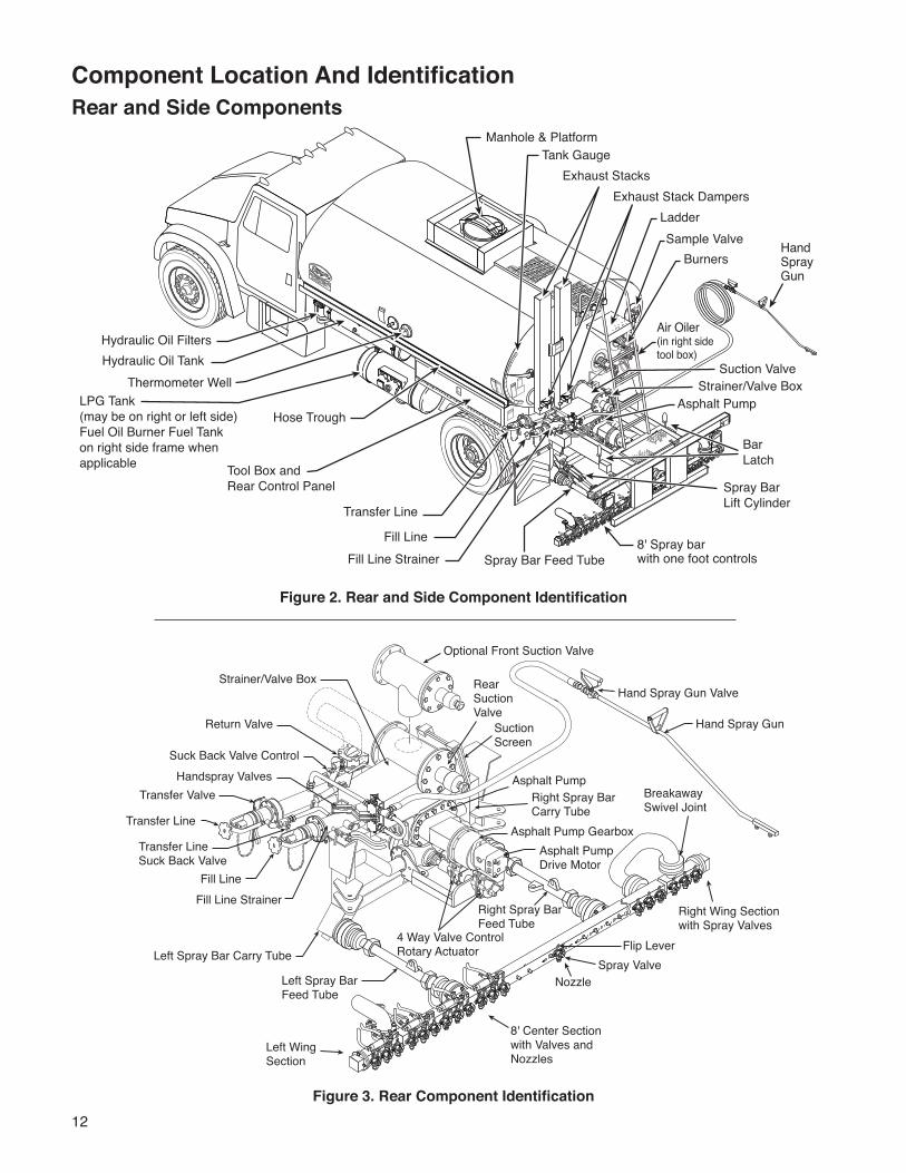
Component Location And IdentificationRear and Side Components
Figure 2. Rear and Side Component Identification
Figure 3. Rear Component Identification
4 Way Valve ControlRotary Actuator
Suction Screen
Optional Front Suction Valve
Rear Suction Valve
Asphalt PumpDrive Motor
Asphalt Pump Gearbox
Right Spray BarCarry Tube
Asphalt Pump
Right Spray BarFeed Tube
Left Spray BarFeed Tube
Hand Spray Gun
Left Spray Bar Carry Tube
Suck Back Valve Control
Strainer/Valve Box
Handspray ValvesTransfer Valve
Return Valve
Transfer Line
Transfer LineSuck Back Valve
Fill LineFill Line Strainer
Hand Spray Gun Valve
Right Wing Sectionwith Spray Valves
Left Wing Section
8' Center Sectionwith Valves and Nozzles
Spray ValveFlip Lever
BreakawaySwivel Joint
Nozzle
20
Hand Spray Gun
Hydraulic Oil TankHydraulic Oil Filters
LPG Tank (may be on right or left side)Fuel Oil Burner Fuel Tank on right side frame when applicable
Hose Trough
Thermometer Well
Tool Box and Rear Control Panel
Manhole & PlatformTank Gauge
Exhaust Stack DampersLadder
BurnersSample Valve
Air Oiler (in right sidetool box)
Suction ValveStrainer/Valve Box
Asphalt Pump
Transfer Line
Fill LineFill Line Strainer
Spray Bar Lift Cylinder
Bar Latch
Spray Bar Feed Tube8' Spray barwith one foot controls
Exhaust Stacks
13
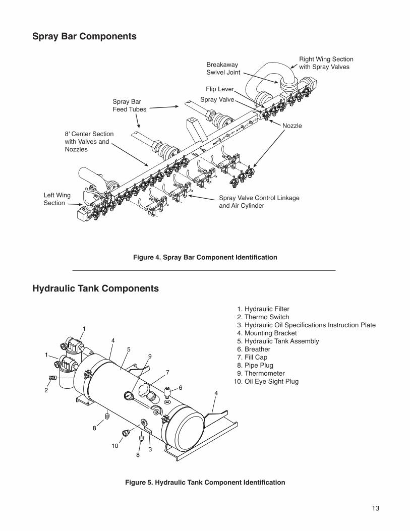
Spray Bar Components
Hydraulic Tank Components
Figure 4. Spray Bar Component Identification
Figure 5. Hydraulic Tank Component Identification
4
1
15
6
7
8
8
9
2
310
4
1. Hydraulic Filter 2. Thermo Switch 3. Hydraulic Oil Specifications Instruction Plate 4. Mounting Bracket 5. Hydraulic Tank Assembly 6. Breather 7. Fill Cap 8. Pipe Plug 9. Thermometer10. Oil Eye Sight Plug
Right Wing Sectionwith Spray Valves
Left Wing Section
8' Center Sectionwith Valves and Nozzles
Spray BarFeed Tubes
Spray ValveFlip Lever
BreakawaySwivel Joint
Nozzle
Spray Valve Control Linkage and Air Cylinder
14
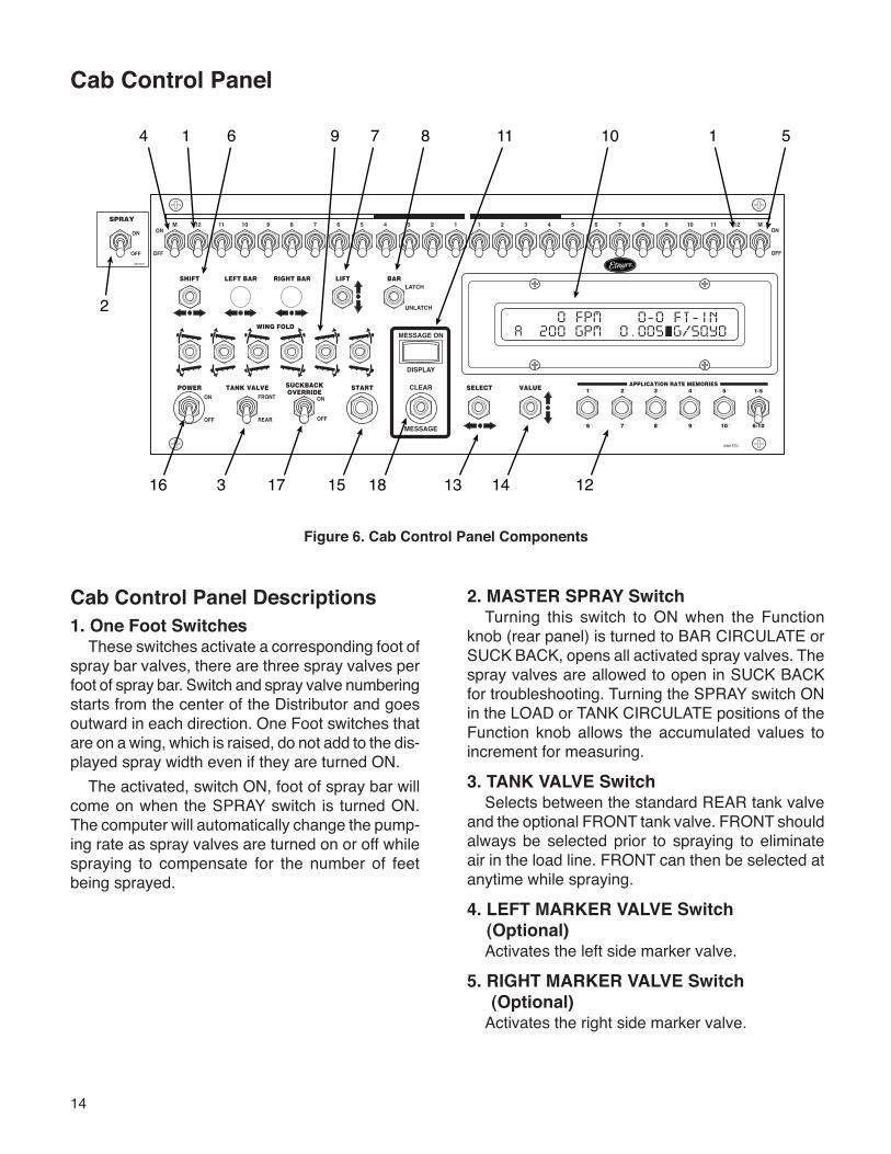
Figure 6. Cab Control Panel Components
Cab Control Panel Descriptions1. One Foot Switches
These switches activate a corresponding foot of spray bar valves, there are three spray valves per foot of spray bar. Switch and spray valve numbering starts from the center of the Distributor and goes outward in each direction. One Foot switches that are on a wing, which is raised, do not add to the dis-played spray width even if they are turned ON.
The activated, switch ON, foot of spray bar will come on when the SPRAY switch is turned ON. The computer will automatically change the pump-ing rate as spray valves are turned on or off while spraying to compensate for the number of feet being sprayed.
2. MASTER SPRAY SwitchTurning this switch to ON when the Function
knob (rear panel) is turned to BAR CIRCULATE or SUCK BACK, opens all activated spray valves. The spray valves are allowed to open in SUCK BACK for troubleshooting. Turning the SPRAY switch ON in the LOAD or TANK CIRCULATE positions of the Function knob allows the accumulated values to increment for measuring.
3. TANK VALVE SwitchSelects between the standard REAR tank valve
and the optional FRONT tank valve. FRONT should always be selected prior to spraying to eliminate air in the load line. FRONT can then be selected at anytime while spraying.
4. LEFT MARKER VALVE Switch (Optional)
Activates the left side marker valve.
5. RIGHT MARKER VALVE Switch (Optional)
Activates the right side marker valve.
Cab Control Panel
1� 2� 3� 4� 5� 6� 7� 8� 9� 10� 11� 12� MM� 12� 11� 10� 9� 8� 7� 6� 5� 4� 3� 2� 1
APPLICATION RATE MEMORIES
�6� 7� 8� 9� 10� 6-10
�1� 2� 3� 4� 5� 1-5
SHIFT LEFT BAR RIGHT BAR LIFT BAR
TANK VALVE START SELECT VALUECLEAR
MESSAGE
MESSAGE ON
DISPLAY
POWER
WING FOLD
LATCH
UNLATCH
ON
OFF
FRONT
REAR
ON
OFF
SUCKBACKOVERRIDE
ON
OFF
ON
OFF3361571
SPRAY
3361570
1
2
3
4 56 7 8
1413 12
11 10
17 18
9
16 15
1
15
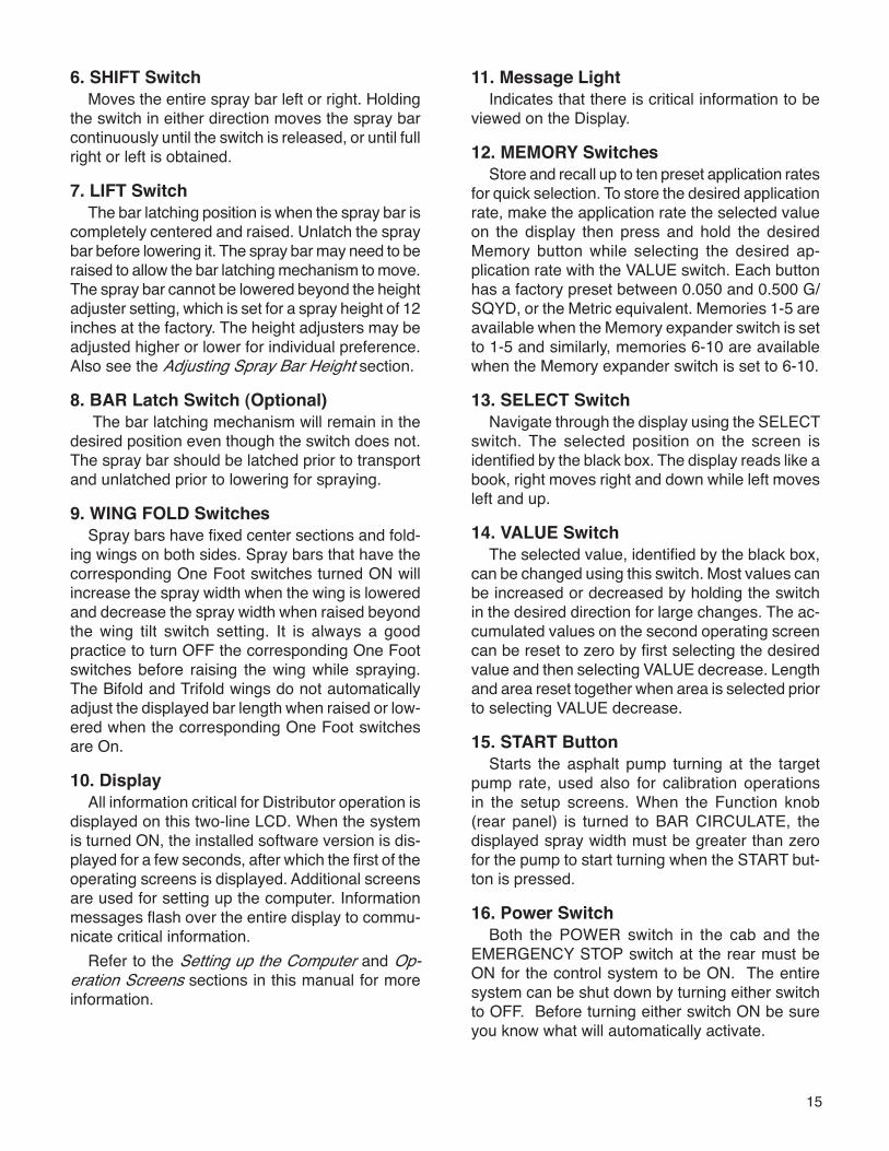
6. SHIFT SwitchMoves the entire spray bar left or right. Holding
the switch in either direction moves the spray bar continuously until the switch is released, or until full right or left is obtained.
7. LIFT SwitchThe bar latching position is when the spray bar is
completely centered and raised. Unlatch the spray bar before lowering it. The spray bar may need to be raised to allow the bar latching mechanism to move. The spray bar cannot be lowered beyond the height adjuster setting, which is set for a spray height of 12 inches at the factory. The height adjusters may be adjusted higher or lower for individual preference. Also see the Adjusting Spray Bar Height section.
8. BAR Latch Switch (Optional) The bar latching mechanism will remain in the
desired position even though the switch does not. The spray bar should be latched prior to transport and unlatched prior to lowering for spraying.
9. WING FOLD SwitchesSpray bars have fixed center sections and fold-
ing wings on both sides. Spray bars that have the corresponding One Foot switches turned ON will increase the spray width when the wing is lowered and decrease the spray width when raised beyond the wing tilt switch setting. It is always a good practice to turn OFF the corresponding One Foot switches before raising the wing while spraying. The Bifold and Trifold wings do not automatically adjust the displayed bar length when raised or low-ered when the corresponding One Foot switches are On.
10. DisplayAll information critical for Distributor operation is
displayed on this two-line LCD. When the system is turned ON, the installed software version is dis-played for a few seconds, after which the first of the operating screens is displayed. Additional screens are used for setting up the computer. Information messages flash over the entire display to commu-nicate critical information.
Refer to the Setting up the Computer and Op-eration Screens sections in this manual for more information.
11. Message LightIndicates that there is critical information to be
viewed on the Display.
12. MEMORY SwitchesStore and recall up to ten preset application rates
for quick selection. To store the desired application rate, make the application rate the selected value on the display then press and hold the desired Memory button while selecting the desired ap-plication rate with the VALUE switch. Each button has a factory preset between 0.050 and 0.500 G/SQYD, or the Metric equivalent. Memories 1-5 are available when the Memory expander switch is set to 1-5 and similarly, memories 6-10 are available when the Memory expander switch is set to 6-10.
13. SELECT SwitchNavigate through the display using the SELECT
switch. The selected position on the screen is identified by the black box. The display reads like a book, right moves right and down while left moves left and up.
14. VALUE SwitchThe selected value, identified by the black box,
can be changed using this switch. Most values can be increased or decreased by holding the switch in the desired direction for large changes. The ac-cumulated values on the second operating screen can be reset to zero by first selecting the desired value and then selecting VALUE decrease. Length and area reset together when area is selected prior to selecting VALUE decrease.
15. START ButtonStarts the asphalt pump turning at the target
pump rate, used also for calibration operations in the setup screens. When the Function knob (rear panel) is turned to BAR CIRCULATE, the displayed spray width must be greater than zero for the pump to start turning when the START but-ton is pressed.
16. Power SwitchBoth the POWER switch in the cab and the
EMERGENCY STOP switch at the rear must be ON for the control system to be ON. The entire system can be shut down by turning either switch to OFF. Before turning either switch ON be sure you know what will automatically activate.
16
Rear Control Panel Descriptions1. PUMP SPEED Control Knob
When MANUAL PUMP CONTROL is selected, turning this knob to the right (clockwise) increases the asphalt pump speed. It is possible to over-speed the asphalt pump in MANUAL control since the asphalt pump speed is also dependent on the engine speed. Always turn the knob back to the left (counter-clockwise) before selecting AUTO PUMP CONTROL or turning ON the POWER switch in the cab or the EMERGENCY STOP switch in the rear panel.
Rear Control Panel
Figure 7. Rear Control Panel Components
2. PUMP CONTROL SwitchWith the switch turned to AUTO, the asphalt
pump speed is controlled at the desired rate through the computer which limits the maximum pump speed to 450 GPM. When the Function knob is set to BAR CIRCULATE, the pump speed is limited to a maximum of 120 GPM. With the switch turned to MANUAL, the asphalt pump speed is controlled with the PUMP SPEED control knob.
In AUTO control, A flashes until the START button is pressed. In MANUAL control, M flashes until the START button is pressed. Use Etnyre computator (p/n 3390408) when spraying in MANUAL control.
SHIFT LEFT BAR RIGHT BAR LIFT BAR
VALUE
SELECT
WING FOLD
LATCH
UNLATCH
BAR CIRCULATE
SUCK BACK
UNLOAD HAND SPRAY
FLUSH
HOME
TANK CIRCULATE
TRANSFER
AUX
LOAD
3361574
EMERGENCY
S T O P
ON
OFF
STARTPUMP CONTROL
ON
OFF
ENGINE HIGH IDLE
PUMPSPEED
MANUAL AUTO
ON
OFF
UPPER BURNER
ON
OFF
LOWER BURNER
CLEAR
MESSAGE
WASH PUMP
RESET
TIMER
511 20 21 1312 10 2 3 4 17
16
615 7 8 114 18 9 19
17. SUCK BACK OVERRIDE SwitchWhen ON, this switch overrides the current set-
ting of the Function knob in the rear panel to the SUCK BACK selection. The SUCK BACK OVER-RIDE must be OFF for the Function knob and the PUMP CONTROL switch to work correctly.
18. CLEAR MESSAGE buttonAfter viewing the current information message(s)
on the display selecting CLEAR MESSAGE will stop the message(s) from being displayed. A new message or selecting a different position on the Function switch will again allow all current informa-
tion messages to be displayed. The MESSAGE ON DISPLAY light will remain ON as long as there are messages to be viewed.
Components Not ShownThe following components are not on the Cab
Control Panel but may be mounted below the panel or on the vehicle’s dash. Such as hour meter, mirror switch(s), beacon, strobe, PTO light.
17
3. START ButtonStarts the asphalt pump turning at the target pump
rate, and also for calibration operations in the setup screens. When the Function knob is turned to BAR CIRCULATE, the displayed spray width must be greater than zero for the pump to start turning when the START button is pressed.
4. ENGINE HIGH IDLE SwitchWhen this option is available and installed, turning
ON this switch makes the engine run at a higher RPM. Turning OFF the switch resumes the engine speed to idle. The high idle setting varies but can be programmed to your preference through your truck dealer. This switch is not disabled through turning OFF power to the controls.
5. Wing Fold SwitchesSpray bars have fixed center sections and folding
wings on both right and left sides. Spray bars that have the corresponding One Foot switches turned ON will increase the spray width when the wing is lowered and decrease the spray width when raised beyond the wing tilt switch setting. It is always a good practice to turn OFF the corre-sponding One Foot switches before raising the wing while spraying. The Bifold and Trifold wings do not automatically adjust the displayed bar length when raised or lowered when the corresponding One Foot switches are On.
6. UPPER BURNER SwitchWhen any burner, fuel oil or LP, with outfire
control is installed, this switch directly controls the upper burner unless optional thermostatic control is also installed. Then it is possible for the switch to be ON when the burner is off. Before operating the burner, refer to the Burner Operation section in this manual.
7. LOWER BURNER SwitchWhen any burner, fuel oil or LP, with outfire
control is installed, this switch directly controls the lower burner unless optional thermostatic control is also installed. Then it is possible for the switch to be ON when the burner is off. Before operating the burner, refer to the Burner Operation section in this manual.
8. Timer Reset SwitchWhen the optional burner controls are in-
stalled, selecting this switch when the burners are operating will extend the heating time.
9. VALUE Switch (Included with optional Display)
The selected value, identified by the black box, can be changed using this switch. Most values can be increased or decreased by holding the switch in the desired direction for large changes. The ac-cumulated values on the second operating screen can be reset to zero by first selecting the desired value and then selecting VALUE decrease. Length and area reset together when area is selected prior to selecting VALUE decrease.
10. CLEAR MESSAGE button (Included with optional Display)
After viewing the current information message(s) on the display selecting CLEAR MESSAGE will stop the message(s) from being displayed. A new message or selecting a different position on the Function switch will again allow all current information messages to be displayed. The MES-SAGE ON DISPLAY light will remain ON as long as there are messages to be viewed.
11. SHIFT SwitchMoves the entire spray bar left or right. Holding
the switch in either direction moves the spray bar continuously until the switch is released, or until full right or left is obtained.
12. LIFT SwitchThe bar latching position is when the spray bar
is completely centered and raised. Unlatch the spray bar before lowering it. The spray bar may need to be raised to allow the bar latching mecha-nism to move. The spray bar cannot be lowered beyond the height adjuster setting, which is set for a spray height of 12 inches at the factory. The height adjusters may be adjusted higher or lower for individual preference. Also see the Adjusting Spray Bar Height section.
13. BAR Latch Switch (Optional)The bar latching mechanism will remain in the
desired position even though the switch does not. The spray bar should be latched prior to transport and unlatched prior to lowering for spraying.
18
14. WASH PUMP Switch and LightWhen the optional solvent pump and switch is
installed turning the switch ON will allow use of the solvent wash wand or application of solvent to the top of the asphalt pump without the pump turning. The light is a reminder that the switch and pump are ON.
15. EMERGENCY STOP SwitchBoth the POWER switch in the cab and the
EMERGENCY STOP switch at the rear must be ON for the control system to be ON. The entire system can be shut down by turning either switch to OFF. Before turning either switch ON be sure you know what will automatically activate. The EMERGENCY STOP switch is turned OFF by pushing in and turned ON by rotating counter clockwise.
16. Front Load Switch (Optional)When the optional front load switch is installed,
selecting Open when in the Load or Transfer posi-tions of the Function knob will open the front load valve. The Closed position allows the use of the standard load line.
17. Display (Optional)All information critical for Distributor operation is
displayed on this two-line LCD. When the system is turned ON, the installed software version is dis-played for a few seconds, after which the first of the operating screens is displayed. Additional screens are used for setting up the computer. Information messages flash over the entire display to commu-nicate critical information.
18. SELECT Switch (Included with optional Display)
Navigate through the display using the SELECT switch. The selected position on the screen is identified by the black box. The display reads like a book, right moves right and down while left moves left and up.
19. Function KnobWhen the desired operation is selected through
this knob, all automatic valves (tank valve, 4-way valve, bar suck back valves, return valve and bal-ance valves) are set for the desired operation, and the asphalt pump stops and when the PUMP CONTROL is in AUTO the stored asphalt pump rate target preset for the desired operation is recalled. Changing the selection after the pump is turning will stop the asphalt pump in AUTO or MANUAL control. When BAR CIRCULATE is selected, the asphalt pump rate target is calculated based on the displayed spray width, application rate, and the setting of the %CIRC factor. For all positions of this switch, except BAR CIRCULATE, the asphalt pump rate preset can be set to op-erator preference by first selecting AUTO PUMP CONTROL. Then before pressing the START but-ton, change the pump rate target to the desired rate and then press the START button to save the desired rate and start the pump turning.
The factory pump rate target presets are (With Metric equivalents also):
• LOAD 100 GPM• TANK CIRCULATE 150 GPM• SUCK BACK 200 GPM• FLUSH 100 GPM• UNLOAD 100 GPM• HAND SPRAY and AUX 50 GPM• TRANSFER 100 GPM• HOME 0 GPM
19
Note: Always refer to the truck chassis owner’s manual for chassis and engine maintenance information.
The following procedures apply to new or rebuilt units.
1. Inspect the unit for damage that may have oc-curred during transporting.
2. Check and tighten all fasteners, body tie-down bolts, pipe and circulating line connections, etc. that may have loosened in transit.
3. Check the fluid level in the hydraulic reservoir. The fluid must always be visible in the sight glass.
WARNINGTo prevent possible personal injury, do not load the vehicle beyond the GAWR or GVWR. The maximum load volume must be calculated based on material density.
Setting Up the ComputerBefore the Distributor is used, the control com-
puter has to to be set for each particular Distributor. The setup screens are used to set parameters and perform calibrations for the Distributor that the con-trol computer is installed in. Setup is performed for the customer at the factory and should not need to be changed except for when major service or repair is performed on the Distributor.
To enter the set up screens hold Memory 6 and 10 buttons down while turning the POWER switch to ON. Then release the buttons. To exit the setup, turn the power OFF. Any changes that are made while in the setup screens are automatically saved.
The SELECT switch is used to navigate through the Setup screens, while the VALUE switch is used to change the value that is selected. The START switch is used to initiate calibration procedures in the Setup screens. Abbreviated instructions for the calibration procedures are displayed for quick recall.
First Screen
This screen allows you to set the display units
and bar control. VALUE increase from English to get Metric. SELECT Switch to the right to enter Bar Control. VALUE decrease from FOOT to get GANG. Value increase from FOOT gives you VW, VW-SMNC, VW-SMC or VW-PROX. These are all variable width spray bar options and not to be used with the Standard 1' Control Spray Bar.
Second Screen
This screen allows the setting of the Spray De-lay On and Off times. The Spray Delay On is the amount of time, in seconds, after the Master Spray switch is turned on that the spray bar valves will be turned on. The Spray Delay Off is the amount of time, in seconds, after the Master Spray switch is turned off that the spray bar valves will be turned off. These delays allow time for the 4-way valve to turn before open and closing the spray bar. Physi-cal delays within the mechanical controls of these valves may have significantly changed and should be addresed before making significant deviations from 0.20 seconds.
Third Screen
This screen allows for selection of the hydraulic motor speed sensor pulses per revolution. The correct setting is dependent upon displacement. Holding the VALUE switch will not continuously increment or decrement the value. Two values are currently valid for the motor: 43 for 1.53 cubic inches per revolution (CIR) motor, and 46 for both 2.1 and 2.69 CIR motors.
This screen is used to set the flow factor. The flow factor is the calibration factor for the asphalt pump. Changing the value from 1000 (100%) does not change the pump flow but does change the displayed pump rate. Values greater than 1000 increase the displayed pump rate while values less than 1000 decrease the displayed pump rate. The flow factor increments or decrements by 0.1% and should only be changed when you are absolutely sure that such a correction needs to be made.
Preparing for Operation
20
Engaging Pump on PTO Equipped Distributors
Start the truck engine. Then, follow one of the procedures below.
Ensure that the truck parking brake is engaged before leaving the cab.
Manual TransmissionsDepress the clutch and pull outward or upward
on the PTO control knob. Slowly let the clutch up. If the PTO fails to engage, depress the clutch pedal and pull up on the PTO handle until engagement occurs. Or, depress the electric air shift PTO switch if your vehicle is so equipped. Increase the engine rpm to a fast idle.
Automatic TransmissionsPush down on the foot brake pedal, move the
gear selector to any forward gear and do one of the following.• Pull upward or outward on the PTO control
knob.• Press the switch activated PTO switch.• Press the electric air shift PTO switch if your
vehicle is so equipped. When the PTO engages, move the gear selector to neutral. If the PTO fails to engage, release the brake pedal slightly while pressing the PTO switch, allowing the truck to inch forward until the PTO engages. Then move the gear selector back to neutral.
Fourth Screen
This screen allows for setting the hydraulic pump EDC threshold in milliamps. The threshold is the minimum required electrical current for the asphalt pump to turn. The threshold is optimally determined at a hydraulic pump speed of 1200 RPM. Threshold settings lower than actual produce instability in the pump control while settings higher than actual do not allow the asphalt pump to be controlled at the lowest speed possible.
This screen also allows the setting of the Start Up Factor (SUF) Time, in seconds. The SUF Time is the amount of time that the %SUF parameter, in the operating screens, adjusts the pump speed im-mediately after the SPRAY switch is turned ON.
Fifth Screen
This screen allows for ground speed calibra-tion. The ground speed is calibrated at the factory through the proper angle and height settings of the radar. Ground speeds that are displayed when the Distributor is parked are most likely due to engine vibrations through the truck frame or reflections off surfaces, such as water. Standing water present while spraying may give incorrect ground speeds. The instructions for calibration are abbreviated on the display.
First mark out a smooth, dry, flat, straight 300 foot path. While driving the Distributor at a constant speed of approximately 300 FPM press START when a fixed point on the truck crosses the first line. Then press the START button again when the same fixed point on the truck crosses the sec-ond line. Once the START button is pressed the first time, BEGIN on the screen changes to END and will change back to BEGIN when pressed the second time.
Sixth Screen
This screen provides the ability to reset param-eters in the computer back to their default values. You should record all of your settings before pro-ceeding. Resetting the parameters will clear all changes to the setup and operating parameters and including all calibrations.
21
WARNINGTo prevent an explosion or fire hazard, do notheat the material beyond the manufacturer’srecommended temperature.
WARNINGTo prevent possible burns to operators or bystanders, or possible equipment damage, do not start any operation if any control settings are unknown.
WARNINGTo prevent severe injury from becoming entangled in machinery, stand clear of rotating drives.
CAUTIONTo prevent possible damage to equipment from material setting up in hose or Distributor, ensure that bitumen in supply tank is heated sufficiently.
Spraying OperationsA correct spray pattern cannot be obtained unless the product is heated to its proper spraying temperature. Cold product will not provide sharp spray edges, and will cause streaking. If heating of the product is required, refer to the section of this manual on Heating Product in Distributors (starting on P. 48) for instruction on operation of your particular type of burners.The computer automatically adjusts the asphalt pump speed to deliver the correct amount of asphalt for the application rate, spray width and vehicle speed. The circulation rate in the bar when not spraying should be set to 50% of the pump speed while spraying. This circulation rate will allow the asphalt pump to reach the desired speed quickly when spraying is started. Circulation rates higher than 50% will result in a heavier start while rates below 50% will produce a lighter start.Spray bar nozzles have a limited flow range at which optimal performance will be achieved. Flow rates greater than this optimal range will cause
excessive overspray. Rates that are too low will cause the fan to sag and cause heavy edges. Refer to the nozzle selection chart in the operator’s manual to select the nozzles appropriate for your conditions.
WARNINGTo prevent an explosion or fire hazard, ensure that the burners are extinguished before removing any material from the tank in any manner. Liquid petroleum (LP) burners can support a flame for several minutes after the fuel supply is turned off.
WARNINGTo prevent an explosion, do not operate the burners when the vehicle is unattended, when the vehicle is in motion, or with the vehicle in a confined area.
WARNINGTo prevent an explosion or fire hazard, when the burners go out, shut off the fuel supply to both burners and allow the flues to ventilate for at least 3 minutes before re-lighting the burners.
WARNINGTo prevent an explosion or fire hazard, do not heat the material beyond the manufacturer’s recommended temperature.
WARNINGTo prevent an explosion or fire hazard, keep burning cigarettes or other sources of combustion away from manholes and overflow vents.
WARNINGTo prevent possible hand or facial burns, always light the inside burner first. Do not reach across a lit burner to light or re-light the inside burner. Shut off the outside burner before lighting the inside burner.
22
WARNINGTo prevent possible burns from material overflow, allow sufficient space in the tank for expansion of the material when heating.
WARNINGTo prevent possible burns to operators or bystanders, or possible equipment damage, do not start any operation if any control settings are unknown.
WARNINGTo prevent possible burns from leaking material, be sure all pipe, cap and hose connections are secure before opening valves.
WARNINGTo prevent possible burns from hot asphalt spray, do not stand, or allow anyone to stand, where accidental opening of a valve may cause contact with hot asphalt.
Setting the Digital Memory PresetsSetting the digital memory presets is not required
to spray. The memory buttons offer the operator a convenient way to store different preset application rates. These settings are saved in the memory even after the power switch has been shut off.
To store an application rate in a memory location, select GAL/SQ YD in the digital display using the SELECT switch.
To set a memory, push that preset button in and hold it. While holding it in, set the application rate to the desired value using the VALUE switch. To raise the application rate hold the VALUE switch up and to lower the application rate, hold the VALUE switch down. When you have the application rate set to the desired value, release the memory but-ton. The displayed application rate will be stored in that memory location until it is over-written with a new application rate using the same procedure.
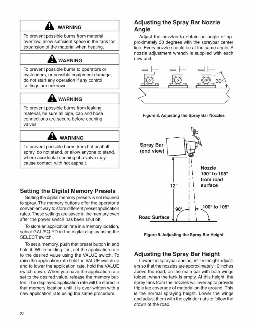
Adjusting the Spray Bar Nozzle Angle
Adjust the nozzles to obtain an angle of ap-proximately 30 degrees with the spraybar center line. Every nozzle should be at the same angle. A nozzle adjustment wrench is supplied with each new unit.
Figure 8. Adjusting the Spray Bar Nozzles
Figure 9. Adjusting the Spray Bar Height
Adjusting the Spray Bar HeightLower the spraybar and adjust the height adjust-
ers so that the nozzles are approximately 12 inches above the road, on the main bar with both wings folded, when the tank is empty. At this height, the spray fans from the nozzles will overlap to provide triple lap coverage of material on the ground. This is the normal spraying height. Lower the wings and adjust them with the cylinder nuts to follow the crown of the road.
23
Tank CapacityThe Centennial Distributor is designed to pump
and spray a variety of asphalt products in an effi-cient and user friendly manner with great accuracy. The Centennial Distributor utilizes a computer to sense the vehicle’s ground speed and control the hydrostatically driven asphalt pump to maintain the set application rate, regardless of variations in vehicle speed or spray bar width in use.
For a complete description of each of the con-trols and how to set up the machine, refer to the Preparing for Operation section of this manual (starting on P. 19).
WARNINGTo prevent possible personal injury, do not load the vehicle beyond the GAWR or GVWR. The maximum load volume must be calculated based on material density.
The Centennial Distributor tank has a built-in air space, or expansion space, above the Tank Full level. This air space is designed to minimize the chance that the tank will overflow if the material in the tank expands due to heating or foaming. This air space should not be used to carry product. The Tank Full level is based on the vehicle’s axle ratings, and, GVWR at a material density of 7.7 lbs/gallon. A lower tank full must be calculated if a product with a density greater than 7.7 lbs/gallon is to be loaded. The lower tank full is calculated by multiplying the original tank full by 7.7 and dividing the result by the new heavier product density.
If you suspect there may be moisture or emul-sion in the tank, Dow-Corning "DC-200" additive can be used to reduce foaming if a product being pumped is at a temperature in excess of 200ºF. Additional DC-200 additive may be obtained from E. D. Etnyre & Co. or your Etnyre dealer.
Operation ScreensThe following screens on the Cab Control Panel
are used during normal operation. Use the SELECT switch to scroll through the values and screens and the VALUE switch to increase or decrease the selected value, when appropriate.
When the system is turned ON the installed soft-ware version is displayed for a few seconds, after which the first operating screen is displayed.
First Operating Screen
The first operating screen displays ground speed, spray width, asphalt pump speed, and appli-cation rate. The application rate is automatically the first selected value and is identified as the selected value with the black box. A or M will also flash in front of the pump rate. When PUMP CONTROL is in AUTO, A will stop flashing after pushing the START button. When PUMP CONTROL is in MANUAL, M will stop flashing after pushing the START button. Spray width is only selectable in gang bar control. Ground speed is never selectable and the pump speed is not selectable in manual pump control, bar circulate, or when spraying.
Second Operating Screen
The second operating screen displays the square yards, gallons sprayed and distance in feet traveled as well as the asphalt tank temperature and target temperature for burner control. The accumulated values can be used for recording shots or the area and distance can be used for dry measuring. The accumulated values will exceed the displayed values after 999,999. The tempera-ture is displayed as 999 when the RTD is not connected to the computer.
Operation
5
24
Third Operating Screen
The third operating screen allows for quick set up of the start-up factor, bar circulation rate factor, and minimum pump speed. The start up factor changes the pump speed for the first half-second of spraying. 100% SUF makes no change. Higher start-up factors increase the pump speed while lower start up factors decrease the pump speed. In BAR CIRCULATE, the asphalt pump rate target is calculated based on the displayed spray width, ap-plication rate, and the setting of the %CIRC factor. A setting of 50% is recommended and is equivalent to half the pump speed required when traveling at a speed of 150 FPM while spraying. The minimum pump speed is used in bar circulate and spray. In either operation, when all of the One Foot switches are turned OFF, the minimum pump speed is not used and the pump speed goes to zero.
Information MessagesThe following messages will be displayed in
order once before they are displayed again. Mes-sages will be displayed only in the main operating screens and will alternate or flash between the message and the current operating screen.
Additional messages will become present if VW is selected for bar control in the setup screens. VW bar control should not be selected for units with FOOT bar control.
Application Pump
These messages will only appear in the spraying operation. The over application message indicates that the ground speed is too slow and/or possibly the engine speed is too fast, while the under ap-plication message indicates that the ground speed is too fast and/or possibly the engine speed is too slow.
Hot Hydraulics
This message flashes on the display when the hydraulic reservoir temperature reaches or exceeds 200º F.
WARNINGStop immediately and determine the cause of the high temperature. Failure to do so will result in damage to hydraulic components.
Switch Module
This message flashes on the display when the input module in the cab control box is not present
25
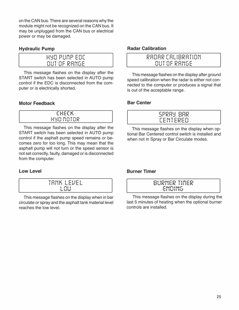
Radar Calibration
This message flashes on the display after ground speed calibration when the radar is either not con-nected to the computer or produces a signal that is out of the acceptable range.
Bar Center
This message flashes on the display when op-tional Bar Centered control switch is installed and when not in Spray or Bar Circulate modes.
on the CAN bus. There are several reasons why the module might not be recognized on the CAN bus. It may be unplugged from the CAN bus or electrical power or may be damaged.
Hydraulic Pump
This message flashes on the display after the START switch has been selected in AUTO pump control if the EDC is disconnected from the com-puter or is electrically shorted.
Motor Feedback
This message flashes on the display after the START switch has been selected in AUTO pump control if the asphalt pump speed remains or be-comes zero for too long. This may mean that the asphalt pump will not turn or the speed sensor is not set correctly, faulty, damaged or is disconnected from the computer.
Low Level
This message flashes on the display when in bar circulate or spray and the asphalt tank material level reaches the low level.
check
Burner Timer
This message flashes on the display during the last 5 minutes of heating when the optional burner controls are installed.
26
Refer to Figure 11 for the following procedures.1. Park the Distributor in the desired location for
loading overhead through the manhole.2. Set the truck parking brake and turn off en-
gine.3. Before exiting the cab, turn the POWER switch
OFF.4. When the desired amount of product is in the
tank and the supply tank valve is closed, close the manhole lid and properly secure before mov-ing the Distributor.
WARNINGTo prevent possible burns from foaming or violent eruption: Do not load tank with material temperature over 200ºF if water or condensation is present in tank, or if emulsion was used in the previous load. Do not heat material over 200ºF if moisture or emulsion is present in tank.
LOADINGLoading Through the Manhole
To reduce the risk of accidental discharge of asphalt, the asphalt pump should not be running, the 4 way valve should be in tank circulate, all tank valves should be closed, and both the load and transfer line caps should be on and secured. when loading through the manhole.
WARNINGTo prevent possible injury, always open the manhole cover slowly. Pressure build up in the tank may cause the cover to burst open.
Figure 11. Valve Positions for Loading Through the Manhole
OFF HANDSPRAY SUCKBACK
Handspray Valve Positions
Return Valve Open
Hand Spray ValveClosed
4 Way ValveCirculate In Tank
Tank ValveClosed
Master Handspray Valves Off
Transfer ValveClosed
Transfer Line Suck Back Valve Closed
Flush ValveClosed
Suck Back Valve Closed
Transfer Line cap �on and secured
Load Line cap on and secured
27
LOADINGLoading Through the Load Line
Connections and Preliminary Checks
WARNINGTo prevent possible burns from leaking material, be sure all pipe, cap and hose connections are secure before opening valves or beginning any operation.
WARNINGTo prevent possible burns to operators or bystanders, or possible equipment damage, do not start any operation if any control settings are unknown.
WARNINGTo prevent an explosion or fire hazard, keep burning cigarettes or other sources of combustion away from manholes and overflow vents.
WARNINGTo prevent burns, always wear eye protection, long sleeve shirt, insulated gloves, boots, and long pants outside the boots when working around the Distributor.
Check StrainersBefore removing the load line cap or strainer
access cover perform the suck back operation to ensure that there is not material in the strainer box. Finally ensure that the tank valve(s) are closed and the POWER switch is OFF before removing the load line cap and stainer access cover.
Ensure that both the fill line and the suction strainers are clean and properly installed.
Ensure that all connections on the Distributor are tight to prevent asphalt leaks. Do not pressurize the fill line with an external pump.
WARNING
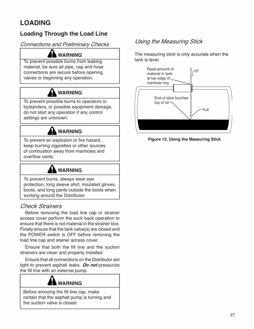
Using the Measuring Stick
The measuring stick is only accurate when the tank is level.
Before emoving the fill line cap, makecertain that the asphalt pump is turning andthe suction valve is closed.
Figure 12. Using the Measuring Stick
28
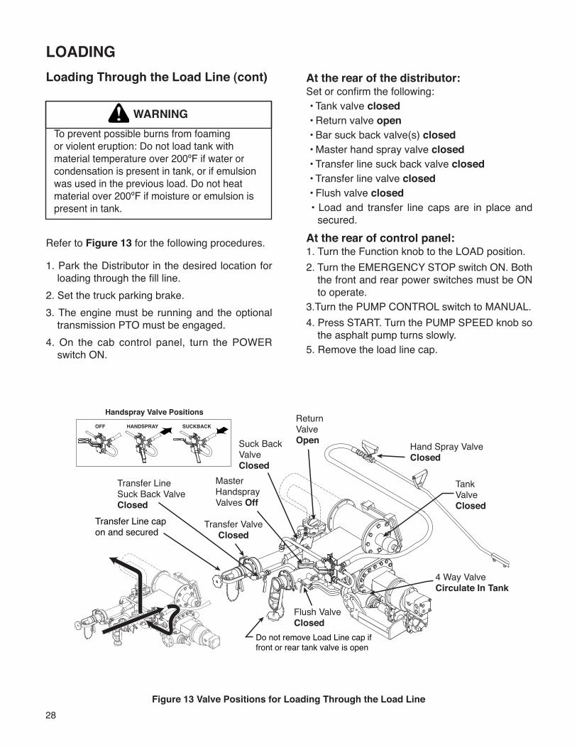
Loading Through the Load Line (cont)
WARNINGTo prevent possible burns from foaming or violent eruption: Do not load tank with material temperature over 200ºF if water or condensation is present in tank, or if emulsion was used in the previous load. Do not heat material over 200ºF if moisture or emulsion is present in tank.
Refer to Figure 13 for the following procedures.
1. Park the Distributor in the desired location for loading through the fill line.
2. Set the truck parking brake.3. The engine must be running and the optional
transmission PTO must be engaged.4. On the cab control panel, turn the POWER
switch ON.
LOADING
OFF HANDSPRAY SUCKBACK
Handspray Valve PositionsReturn Valve Open Hand Spray Valve
Closed
4 Way ValveCirculate In Tank
Tank ValveClosed
Master Handspray Valves Off
Transfer ValveClosed
Transfer Line Suck Back Valve Closed
Flush ValveClosed
Suck Back Valve Closed
Transfer Line cap �on and secured
Do not remove Load Line cap if front or rear tank valve is open
Figure 13 Valve Positions for Loading Through the Load Line
At the rear of the distributor:Set or confirm the following: • Tank valve closed • Return valve open • Bar suck back valve(s) closed • Master hand spray valve closed • Transfer line suck back valve closed • Transfer line valve closed • Flush valve closed • Load and transfer line caps are in place and
secured.At the rear of control panel:1. Turn the Function knob to the LOAD position.2. Turn the EMERGENCY STOP switch ON. Both
the front and rear power switches must be ON to operate.
3.Turn the PUMP CONTROL switch to MANUAL.4. Press START. Turn the PUMP SPEED knob so
the asphalt pump turns slowly.5. Remove the load line cap.
29
6. Connect the load line to the supply tank through an asphalt hose. 7. Open the tank valve on the supply tank. 8. Decrease the PUMP SPEED to zero. 9. Turn the PUMP CONTROL switch to AUTO.10. Press START. The pump will start turning at the
desired loading rate.11. When the desired amount of product is in the
Distributor tank, close the supply tank valve.12. At the supply tank, carefully open the bleeder
valve or break the hose connection until a strong vacuum is heard. It may be necessary to reduce the pump speed in order to over-come pump vacuum when breaking the hose connection. Elevating the hose above the load line connection will allow maximum drainage of the hose.
13. Disconnect the hose from the load line.14. Replace the load line cap and secure.15. If no other operation will be performed, it may
be necessary to flush the pump before stopping the pump in the next step. Otherwise go to the instructions for the desired operation.
16. To stop the pump in MANUAL control select AUTO control. To stop the pump in AUTO con-trol, with the PUMP SPEED knob fully counter clockwise select MANUAL control.
NOTE: The pump can be stopped and the auto-matic tank valve can be closed immediately at any time during operation by turning the EMERGENCY STOP switch OFF. Before turning the EMERGEN-CY STOP switch back ON, turn the PUMP SPEED knob to zero to prevent the pump from turning.
A pump rate of 100 GPM is recommended to begin the loading operation. The pump rate can be increased at any time after loading has begun.
Depending on material viscosity, as the loading rate is increased, the asphalt pump may cavitate. When this happens, the pump will make a distinc-tive sound, easily recognized with experience. Short periods of operation while the pump is cavi-tating will not damage the pump but you should not operate the pump in this condition for extended periods.
Higher pump speeds will not load thicker mate-rials faster. Lighter materials, or heavy materials which are already at spraying temperature, may be loaded at faster rates.
WARNINGTo prevent possible burns from material overflow, allow sufficient space in the tank for expansion of the material when heating.
WARNINGTo prevent an explosion or fire hazard, keep burning cigarettes or other sources of combustion away from manholes and overflow vents.
WARNINGTo prevent burns, always wear insulated gloves when handling spray bar sections or hoses.
30
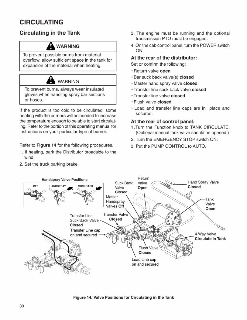
CIRCULATING
WARNINGTo prevent possible burns from material overflow, allow sufficient space in the tank for expansion of the material when heating.
WARNING
If the product is too cold to be circulated, some heating with the burners will be needed to increase the temperature enough to be able to start circulat-ing. Refer to the portion of this operating manual for instructions on your particular type of burner.
Refer to Figure 14 for the following procedures.1. If heating, park the Distributor broadside to the
wind.2. Set the truck parking brake.
Circulating in the Tank 3. The engine must be running and the optional transmission PTO must be engaged.
4. On the cab control panel, turn the POWER switch ON.
At the rear of the distributor:Set or confirm the following:• Return valve open• Bar suck back valve(s) closed• Master hand spray valve closed• Transfer line suck back valve closed• Transfer line valve closed• Flush valve closed• Load and transfer line caps are in place and
secured.
At the rear of control panel:1.Turn the Function knob to TANK CIRCULATE.
(Optional manual tank valve should be opened.)2. Turn the EMERGENCY STOP switch ON.3. Put the PUMP CONTROL to AUTO.
OFF HANDSPRAY SUCKBACK
Handspray Valve Positions Return Valve Open
Hand Spray ValveClosed
4 Way ValveCirculate In Tank
Tank ValveOpen
Master Handspray Valves Off
Transfer ValveClosed
Transfer Line Suck Back Valve Closed
Flush ValveClosed
Suck Back Valve Closed
Transfer Line cap �on and secured
Load Line cap on and secured
Figure 14. Valve Positions for Circulating in the Tank
To prevent burns, always wear insulatedgloves when handling spray bar sectionsor hoses.
31
4. Press START. The pump will start turning at the desired circulation rate.
5. If no other operation will be performed, go to the next step. Otherwise go to the instructions for the desired operation.
6. The optional manual tank valve should be closed at this time before stopping the pump.
7. To stop the pump in MANUAL control select AUTO control. To stop the pump in AUTO con-trol, with the PUMP SPEED knob fully counter clockwise select MANUAL control.
8. Flush the pump if necessary before quitting.NOTE: The pump can be stopped and the auto-
matic tank valve can be closed immediately at any time during operation by turning the EMERGENCY STOP switch OFF. Before turning the EMERGEN-CY STOP switch back ON, turn the PUMP SPEED to zero to prevent the pump from turning.
WARNINGTo prevent possible burns, use extreme caution when using a torch to heat the pump. Asphalt accumulated around the pump may ignite when heating the pump with a torch.
WARNINGTo prevent an explosion or fire hazard, when the burners go out, shut off the fuel supply to both burners and allow the flues to ventilate for at least 3 minutes before re-lighting the burners.
WARNINGTo prevent an explosion, do not operate the burners when the vehicle is unattended, when the vehicle is in motion, or with the vehicle in a confined area.
WARNINGTo prevent possible burns from material overflow, allow sufficient space in the tank for expansion of the material when heating.
32
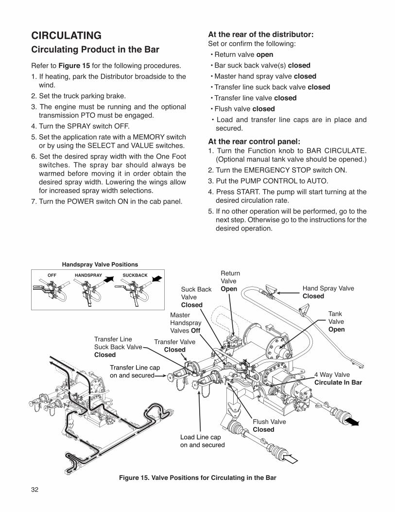
Circulating Product in the BarRefer to Figure 15 for the following procedures.1. If heating, park the Distributor broadside to the
wind.2. Set the truck parking brake.3. The engine must be running and the optional
transmission PTO must be engaged.4. Turn the SPRAY switch OFF.5. Set the application rate with a MEMORY switch
or by using the SELECT and VALUE switches.6. Set the desired spray width with the One Foot
switches. The spray bar should always be warmed before moving it in order obtain the desired spray width. Lowering the wings allow for increased spray width selections.
7. Turn the POWER switch ON in the cab panel.
Figure 15. Valve Positions for Circulating in the Bar
At the rear of the distributor:Set or confirm the following: • Return valve open • Bar suck back valve(s) closed • Master hand spray valve closed • Transfer line suck back valve closed • Transfer line valve closed • Flush valve closed • Load and transfer line caps are in place and
secured.
At the rear control panel:1. Turn the Function knob to BAR CIRCULATE.
(Optional manual tank valve should be opened.)2. Turn the EMERGENCY STOP switch ON.3. Put the PUMP CONTROL to AUTO.4. Press START. The pump will start turning at the
desired circulation rate.5. If no other operation will be performed, go to the
next step. Otherwise go to the instructions for the desired operation.
OFF HANDSPRAY SUCKBACK
Handspray Valve PositionsReturn Valve Open Hand Spray Valve
Closed
4 Way ValveCirculate In Bar
Tank ValveOpen
Master Handspray Valves Off
Transfer ValveClosed
Transfer Line Suck Back Valve Closed
Flush ValveClosed
Suck Back Valve Closed
Transfer Line cap �on and secured
Load Line cap on and secured
CIRCULATING
33
WARNINGTo prevent an explosion or fire hazard, ensure that the burners are extinguished before removing any material from the tank in any manner. Liquid petroleum (LP) burners can support a flame for several minutes after the fuel supply is turned off.
CAUTIONTo prevent excessive pressure in the spray bar, the asphalt pump speed should no exceed 160 GPM while circulating in the spray bar.
NOTE: The pump can be stopped and the auto-matic tank valve can be closed immediately at any time during operation by turning the EMERGENCY STOP switch OFF. Before turning the EMERGEN-CY STOP switch back ON, turn the PUMP SPEED to zero to prevent the pump from turning.Circulate product long enough to ensure removal of all air from the bar and to heat the spray bar valves sufficiently. For better material circulation, in the bar ends, the wings should be lowered. Before moving the bar, circulate some hot material through the bar. This allows the bar to warm up and also extends the life of the bar seals and O-rings.
34
Spraying Through the BarRefer to Figure 16 for valve positions.1. Complete the procedure for circulating in the
spray bar. See the Circulating Product in the Bar section of this manual starting on P.32.
2. Unlatch the spray bar.3. Lower the spray bar to the desired spray
height.4. Set the desired spray width using the One Foot
switches and configuring the spray bar to the desired width with the wings. Extend or retract the right and left spray bars as needed.
5. Select the transmission gear and rear axle speed that produces the desired engine and ground speed for spraying.
6. Release the parking brake and start the Distribu-tor moving.
Figure 16. Valve Positions for Spraying Through the Bar
7. When the spray bar reaches the beginning of the shot, turn the SPRAY switch ON.
8. When the spray bar reaches the end of the shot turn the SPRAY switch OFF.
9. Continue spraying by turning ON and OFF the SPRAY switch as desired. When finished, follow the instructions for bar suck back. See the Spray Bar Suck Back section starting on P. 36.
WARNINGDo not run the pump above rated capacity of 400 GPM. Damage to equipment may occur.
WARNINGTo prevent an explosion or fire hazard, do not operate the burners while spraying.
OFF HANDSPRAY SUCKBACK
Handspray Valve Positions
Return Valve Closed
Hand Spray ValveClosed
4 Way ValveSpray
Tank ValveOpen
Master Handspray Valves Off
Transfer ValveClosed
Transfer Line Suck Back Valve Closed
Flush ValveClosed
Suck Back Valve Closed
Transfer Line cap �on and secured
Load Line cap on and secured
SPRAYING
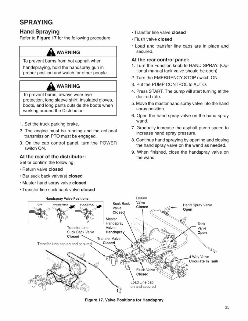
35
Hand SprayingRefer to Figure 17 for the following procedure.
WARNINGTo prevent burns from hot asphalt whenhandspraying, hold the handspray gun in proper position and watch for other people.
WARNINGTo prevent burns, always wear eye protection, long sleeve shirt, insulated gloves, boots, and long pants outside the boots when working around the Distributor.
1. Set the truck parking brake.2. The engine must be running and the optional
transmission PTO must be engaged.3. On the cab control panel, turn the POWER
switch ON.
At the rear of the distributor:Set or confirm the following:• Return valve closed• Bar suck back valve(s) closed• Master hand spray valve closed• Transfer line suck back valve closed
Figure 17. Valve Positions for Handspray
• Transfer line valve closed• Flush valve closed• Load and transfer line caps are in place and
secured.
At the rear control panel:1. Turn the Function knob to HAND SPRAY. (Op-
tional manual tank valve should be open)2. Turn the EMERGENCY STOP switch ON.3. Put the PUMP CONTROL to AUTO.4. Press START. The pump will start turning at the
desired rate.5. Move the master hand spray valve into the hand
spray position.6. Open the hand spray valve on the hand spray
wand.7. Gradually increase the asphalt pump speed to
increase hand spray pressure.8. Continue hand spraying by opening and closing
the hand spray valve on the wand as needed.9. When finished, close the handspray valve on
the wand.
OFF HANDSPRAY SUCKBACK
Handspray Valve Positions Return Valve Closed Hand Spray Valve
Open
4 Way ValveCirculate In Tank
Tank ValveOpen
Master Handspray Valves Handspray
Transfer ValveClosed
Transfer Line Suck Back Valve Closed
Flush ValveClosed
Suck Back Valve Closed
Transfer Line cap on and secured
Load Line cap on and secured
SPRAYING
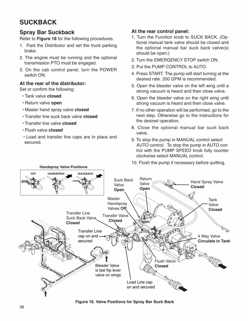
36
Spray Bar SuckbackRefer to Figure 18 for the following procedures.1. Park the Distributor and set the truck parking
brake.2. The engine must be running and the optional
transmission PTO must be engaged.3. On the cab control panel, turn the POWER
switch ON.
At the rear of the distributor:Set or confirm the following: • Tank valve closed • Return valve open • Master hand spray valve closed • Transfer line suck back valve closed • Transfer line valve closed • Flush valve closed • Load and transfer line caps are in place and
secured.
At the rear control panel:1. Turn the Function knob to SUCK BACK. (Op-
tional manual tank valve should be closed and the optional manual bar suck back valve(s) should be open.)
2. Turn the EMERGENCY STOP switch ON.3. Put the PUMP CONTROL to AUTO.4. Press START. The pump will start turning at the
desired rate. 200 GPM is recommended.5. Open the bleeder valve on the left wing until a
strong vacuum is heard and then close valve.6. Open the bleeder valve on the right wing until
strong vacuum is heard and then close valve.7. If no other operation will be performed, go to the
next step. Otherwise go to the instructions for the desired operation.
8. Close the optional manual bar suck back valve.
9. To stop the pump in MANUAL control select AUTO control. To stop the pump in AUTO con trol with the PUMP SPEED knob fully counter clockwise select MANUAL control.
10. Flush the pump if necessary before quitting.
Figure 18. Valve Positions for Spray Bar Suck Back
OFF HANDSPRAY SUCKBACK
Handspray Valve Positions
Return Valve Open
Hand Spray ValveClosed
4 Way ValveCirculate in Tank
Tank ValveClosed
Master Handspray Valves Off
Transfer ValveClosed
Transfer Line Suck Back Valve Closed
Flush ValveClosed
Suck Back Valve Open
Transfer Line cap on and secured
Load Line cap on and secured
Bleeder Valve is last flip lever valve on wings
SUCKBACK
37
NOTE: The pump can be stopped and the auto-matic tank valve can be closed immediately at any time during operation by turning the EMERGENCY STOP switch OFF. Before turning the EMERGEN-CY STOP switch back ON, turn the PUMP SPEED to zero to prevent the pump from turning.
WARNINGTo prevent possible burns from hot asphalt spray, do not stand, or allow anyone to stand, where accidental opening of a valve may cause contact with hot asphalt.
When using rear pump control, engine RPMchanges will affect asphalt pump speed.
CAUTION
For asphalts like AC it is recommended that this procedure be repeated a second time, after which adding solvent such as diesel fuel through each bleeder will quickly flush the spray bar.
If not equipped with the electric pump, it is help-ful to pour some diesel fuel down the fill line after all operations are completed. The diesel fuel will remain in the pump overnight to keep the pump free for the next morning’s operation.
Ensure that the self flush valve is closed at the end of this function, or before loading or circulating asphalt to eliminate chances of inducing asphalt into the self flush fuel tank.
38
Suck Back OverrideThis optional feature is designed for quick in-cab switching between bar circulate and bar suck back for units equipped with automatic tank and bar suck back valves. When the SUCK BACK OVERRIDE switch is ON, all automatically controlled valves are set to their correct positions for SUCK BACK. This overrides any settings of the Function knob and also stops the asphalt pump.
The following steps performed in the cab while the Function knob is turned to BAR CIRCULATE.1. Turn the SUCK BACK OVERRIDE switch ON.2. Press START. The pump will start turning at the
desired rate. 200 GPM is recommended.3. If complete bar suck back is desired, follow the
instructions for bar suck back, beginning with the opening of the left bleeder valve. Otherwise continue to the next step.
4. Turn the SUCK BACK OVERRIDE switch OFF.
5. Press START. The pump will start turning at the desired circulation rate.
SUCKBACK
When using rear pump control, engine RPMchanges will affect asphalt pump speed.
CAUTION
WARNING
To prevent burns, always wear eye protection,long sleeve shirt, insulated gloves, boots andlong pants outside the boots when workingaround the Distributor.
Note: The pump can be stopped and the automatic tank valve can be closed immediately at any time during operation by turning the EMERGENCY STOP switch OFF. Before turning the EMERGENCY STOP switch back ON, turn the PUMP SPEED to zero to prevent the pump from turning.
39
1. Turn the Function knob to SUCK BACK (Optional manual tank valve should be
closed).2. Press START. The pump will start turning at the
desired rate, 200 GPM is recommended.3. Move the master hand spray valve into the suck
back position.4. Open the hand spray valve on the hand spray
wand until a strong vacuum is heard and then close the valve.
5. If no other operation will be performed, go to the next step. Otherwise go to the instructions for the desired operation.
6. To stop the pump in MANUAL control select AUTO control. To stop the pump in AUTO con-trol with the PUMP SPEED knob fully counter clockwise select MANUAL control.
7. Flush the pump if necessary before quitting.
SUCKBACKHandspray Suckback
WARNING
To prevent burns from hot asphalt whenhandspraying, hold the handspray gun inproper position and watch for other people.
WARNING
To prevent burns, always wear eye protection,long sleeve shirt, insulated gloves, boots andlong pants outside the boots when workingaround the Distributor.
NOTE: The pump can be stopped and the auto-matic tank valve can be closed immediately at any time during operation by turning the EMERGENCY STOP switch OFF. Before turning the EMERGEN-CY STOP switch back ON, turn the PUMP SPEED to zero to prevent the pump from turning.
WARNINGTo prevent possible burns from hot asphalt spray, do not stand, or allow anyone to stand, where accidental opening of a valve may cause contact with hot asphalt.
For asphalts like AC it is recommended that this procedure be repeated a second time, after which adding solvent such as diesel fuel through the nozzles of the hand spray wand will quickly flush the hand spray wand and hose.
If not equipped with the electric pump, it is help-ful to pour some diesel fuel down the fill line after all operations are completed. The diesel fuel will remain in the pump overnight to keep the pump free for the next morning’s operation.
Ensure that the self flush valve is closed at the end of this function, or before loading or circulating asphalt to eliminate chances of inducing asphalt into the self flush fuel tank.
CAUTIONWhen using rear pump control, engine RPM changes will affect asphalt pump speed.
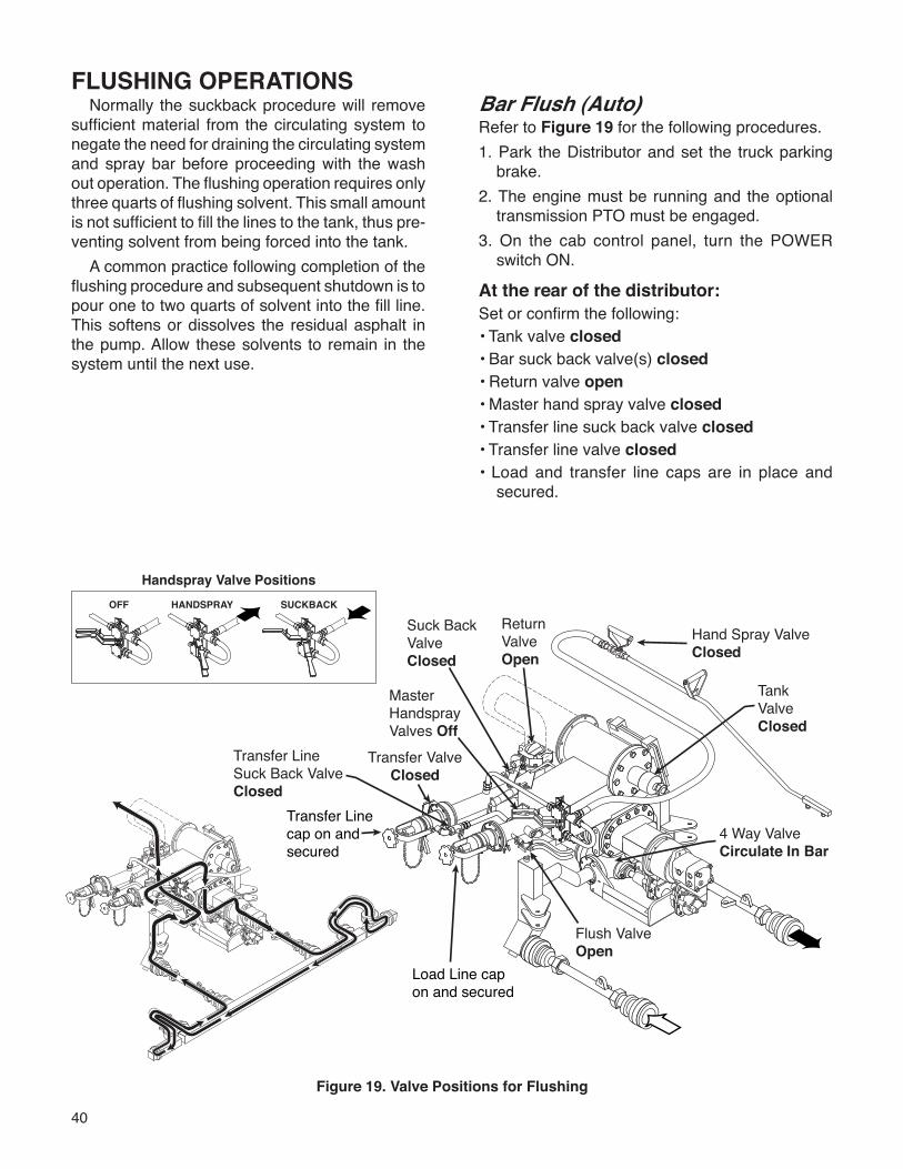
40
FLUSHING OPERATIONSNormally the suckback procedure will remove
sufficient material from the circulating system to negate the need for draining the circulating system and spray bar before proceeding with the wash out operation. The flushing operation requires only three quarts of flushing solvent. This small amount is not sufficient to fill the lines to the tank, thus pre-venting solvent from being forced into the tank.
A common practice following completion of the flushing procedure and subsequent shutdown is to pour one to two quarts of solvent into the fill line. This softens or dissolves the residual asphalt in the pump. Allow these solvents to remain in the system until the next use.
Figure 19. Valve Positions for Flushing
Bar Flush (Auto)Refer to Figure 19 for the following procedures.1. Park the Distributor and set the truck parking
brake.2. The engine must be running and the optional
transmission PTO must be engaged.3. On the cab control panel, turn the POWER
switch ON.
At the rear of the distributor:Set or confirm the following:• Tank valve closed• Bar suck back valve(s) closed• Return valve open• Master hand spray valve closed• Transfer line suck back valve closed• Transfer line valve closed• Load and transfer line caps are in place and
secured.
OFF HANDSPRAY SUCKBACK
Handspray Valve Positions
Return Valve Open
Hand Spray ValveClosed
4 Way ValveCirculate In Bar
Tank ValveClosed
Master Handspray Valves Off
Transfer ValveClosed
Transfer Line Suck Back Valve Closed
Flush ValveOpen
Suck Back Valve Closed
Transfer Line cap on and secured
Load Line cap on and secured
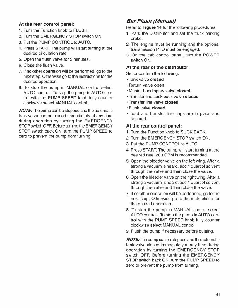
41
At the rear control panel:1. Turn the Function knob to FLUSH.2. Turn the EMERGENCY STOP switch ON.3. Put the PUMP CONTROL to AUTO.4. Press START. The pump will start turning at the
desired circulation rate.5. Open the flush valve for 2 minutes.6. Close the flush valve.7. If no other operation will be performed, go to the
next step. Otherwise go to the instructions for the desired operation.
8. To stop the pump in MANUAL control select AUTO control. To stop the pump in AUTO con-trol with the PUMP SPEED knob fully counter clockwise select MANUAL control.
NOTE: The pump can be stopped and the automatic tank valve can be closed immediately at any time during operation by turning the EMERGENCY STOP switch OFF. Before turning the EMERGENCY STOP switch back ON, turn the PUMP SPEED to zero to prevent the pump from turning.
Bar Flush (Manual)Refer to Figure 14 for the following procedures.1. Park the Distributor and set the truck parking
brake.2. The engine must be running and the optional
transmission PTO must be engaged.3. On the cab control panel, turn the POWER
switch ON.At the rear of the distributor:Set or confirm the following:• Tank valve closed• Return valve open• Master hand spray valve closed• Transfer line suck back valve closed• Transfer line valve closed• Flush valve closed• Load and transfer line caps are in place and
secured.At the rear control panel:1. Turn the Function knob to SUCK BACK.2. Turn the EMERGENCY STOP switch ON.3. Put the PUMP CONTROL to AUTO.4. Press START. The pump will start turning at the
desired rate. 200 GPM is recommended.5. Open the bleeder valve on the left wing. After a
strong a vacuum is heard, add 1 quart of solvent through the valve and then close the valve.
6. Open the bleeder valve on the right wing. After a strong a vacuum is heard, add 1 quart of solvent through the valve and then close the valve.
7. If no other operation will be performed, go to the next step. Otherwise go to the instructions for the desired operation.
8. To stop the pump in MANUAL control select AUTO control. To stop the pump in AUTO con-trol with the PUMP SPEED knob fully counter clockwise select MANUAL control.
9. Flush the pump if necessary before quitting.
NOTE: The pump can be stopped and the automatic tank valve closed immediately at any time during operation by turning the EMERGENCY STOP switch OFF. Before turning the EMERGENCY STOP switch back ON, turn the PUMP SPEED to zero to prevent the pump from turning.
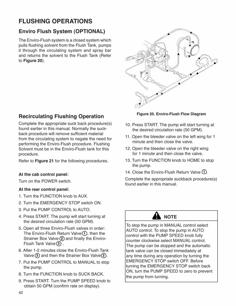
42
FLUSHING OPERATIONSEnviro Flush System (OPTIONAL)The Enviro-Flush system is a closed system which pulls flushing solvent from the Flush Tank, pumps it through the circulating system and spray bar and returns the solvent to the Flush Tank (Refer to Figure 20).
Figure 20. Enviro-Flush Flow DiagramRecirculating Flushing OperationComplete the appropriate suck back procedure(s) found earlier in this manual. Normally the suck-back procedure will remove sufficient material from the circulating system to negate the need for performing the Enviro-Flush procedure. Flushing Solvent must be in the Enviro-Flush tank for this procedure.Refer to Figure 21 for the following procedures.
At the cab control panel:Turn on the POWER switch.
10. Press START. The pump will start turning at the desired circulation rate (50 GPM).11. Open the bleeder valve on the left wing for 1 minute and then close the valve.12. Open the bleeder valve on the right wing for 1 minute and then close the valve.13. Turn the FUNCTION knob to HOME to stop the pump.14. Close the Enviro-Flush Return Valve .Complete the appropriate suckback procedure(s) found earlier in this manual.
1
At the rear control panel:1. Turn the FUNCTION knob to AUX.2. Turn the EMERGENCY STOP switch ON.3. Put the PUMP CONTROL to AUTO.4. Press START. The pump will start turning at the desired circulation rate (50 GPM).5. Open all three Enviro-Flush valves in order: The Enviro-Flush Return Valve , then the Strainer Box Valve and finally the Enviro- Flush Tank Valve .6. After 1-2 minutes close the Enviro-Flush Tank Valve and then the Strainer Box Valve .7. Put the PUMP CONTROL to MANUAL to stop the pump.8. Turn the FUNCTION knob to SUCK BACK.9. Press START. Turn the PUMP SPEED knob to obtain 50 GPM (confirm rate on display).
12
3
3 2
NOTETo stop the pump in MANUAL control select AUTO control. To stop the pump in AUTO control with the PUMP SPEED knob fully counter clockwise select MANUAL control. The pump can be stopped and the automatic tank valve can be closed immediately at any time during any operation by turning the EMERGENCY STOP switch OFF. Before turning the EMERGENCY STOP switch back ON, turn the PUMP SPEED to zero to prevent the pump from turning.
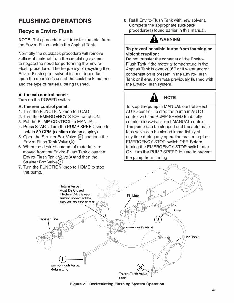
43
Transfer Line
open
Return ValveMust Be ClosedIf Return Valve is open flushing solvent will be emptied into asphalt tank
1Enviro-Flush Valve, Return Line
Enviro-Flush Valve, Tank
3
Flush TankFlush Tank
4-way valve
2
Fill Line
FLUSHING OPERATIONSRecycle Enviro FlushNOTE: This procedure will transfer material from the Enviro-Flush tank to the Asphalt Tank.
Normally the suckback procedure will remove sufficient material from the circulating system to negate the need for performing the Enviro-Flush procedure. The frequency of recycling the Enviro-Flush spent solvent is then dependant upon the operator’s use of the suck back feature and the type of material being flushed.
At the cab control panel:Turn on the POWER switch.At the rear control panel:1. Turn the FUNCTION knob to LOAD.2. Turn the EMERGENCY STOP switch ON.3. Put the PUMP CONTROL to MANUAL.4. Press START. Turn the PUMP SPEED knob to obtain 50 GPM (confirm rate on display).5. Open the Strainer Box Valve and then the Enviro-Flush Tank Valve . 6. When the desired amount of material is re- moved from the Enviro-Flush Tank close the Enviro-Flush Tank Valve and then the
Strainer Box Valve .7. Turn the FUNCTION knob to HOME to stop the pump.
23
32
8. Refill Enviro-Flush Tank with new solvent. Complete the appropriate suckback procedure(s) found earlier in this manual.
To prevent possible burns from foaming or violent eruption:Do not transfer the contents of the Enviro-Flush Tank if the material temperature in the Asphalt Tank is over 200ºF or if water and/or condensation is present in the Enviro-Flush Tank or if emulsion was previously flushed with the Enviro-Flush system.
WARNING
To stop the pump in MANUAL control select AUTO control. To stop the pump in AUTO control with the PUMP SPEED knob fully counter clockwise select MANUAL control. The pump can be stopped and the automatic tank valve can be closed immediately at any time during any operation by turning the EMERGENCY STOP switch OFF. Before turning the EMERGENCY STOP switch back ON, turn the PUMP SPEED to zero to prevent the pump from turning.
NOTE
Figure 21. Recirculating Flushing System Operation
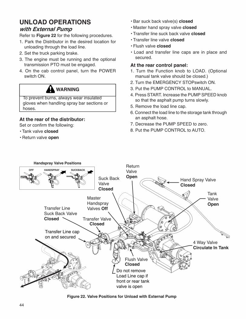
44
Figure 22. Valve Positions for Unload with External Pump
UNLOAD OPERATIONSwith External PumpRefer to Figure 22 for the following procedures.1. Park the Distributor in the desired location for
unloading through the load line.2. Set the truck parking brake.3. The engine must be running and the optional
transmission PTO must be engaged.4. On the cab control panel, turn the POWER
switch ON.
WARNINGTo prevent burns, always wear insulated gloves when handling spray bar sections or hoses.
At the rear of the distributor:Set or confirm the following:• Tank valve closed• Return valve open
• Bar suck back valve(s) closed• Master hand spray valve closed• Transfer line suck back valve closed• Transfer line valve closed• Flush valve closed• Load and transfer line caps are in place and
secured.At the rear control panel:1. Turn the Function knob to LOAD. (Optional
manual tank valve should be closed.)2. Turn the EMERGENCY STOPswitch ON.3. Put the PUMP CONTROL to MANUAL.4. Press START. Increase the PUMP SPEED knob
so that the asphalt pump turns slowly.5. Remove the load line cap.6. Connect the load line to the storage tank through
an asphalt hose.7. Decrease the PUMP SPEED to zero.8. Put the PUMP CONTROL to AUTO.
OFF HANDSPRAY SUCKBACK
Handspray Valve PositionsReturn Valve Open Hand Spray Valve
Closed
4 Way ValveCirculate In Tank
Tank ValveOpen
Master Handspray Valves Off
Transfer ValveClosed
Transfer Line Suck Back Valve Closed
Flush ValveClosed
Suck Back Valve Closed
Transfer Line cap �on and secured
Do not removeLoad Line cap if front or rear tankvalve is open
45
NOTE: The pump can be stopped and the auto- matic tank valve can be closed immediately at any time during operation by turning the EMERGENCY STOP switch OFF. Before turning the EMERGENCY STOP switch back ON, turn the PUMP SPEED to zero to prevent the pump from turning.
WARNINGTo prevent burns, always wear insulated gloves when handling spray bar sections or hoses.
9. Turn the Function knob to UNLOAD (the optional manual tank valve should be open).10. Open any valves on the storage tank between
the asphalt hose and the tank.11. Run the asphalt pump on the storage tank at
the desired pump speed.12. When finished unloading, turn the Function
knob to HOME (the optional manual tank valve should be closed).
13. As the load line on the Distributor is being un-loaded, carefully open the bleeder valve or break the hose connection until a strong vacuum is heard. It may be necessary to reduce the pump speed in order to overcome pump vacuum when breaking the hose connection. Elevating the hose above the storage tank connection will allow maximum drainage of the hose.
14. Disconnect the hose from the load line.15. Replace the load line cap and secure.16. Flush the pump before quitting.
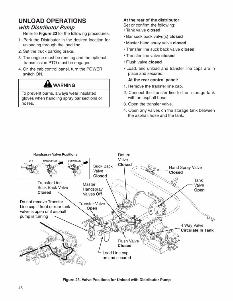
46
UNLOAD OPERATIONSwith Distributor Pump
Refer to Figure 23 for the following procedures.1. Park the Distributor in the desired location for
unloading through the load line.2. Set the truck parking brake.3. The engine must be running and the optional
transmission PTO must be engaged.4. On the cab control panel, turn the POWER
switch ON.
WARNINGTo prevent burns, always wear insulated gloves when handling spray bar sections or hoses.
At the rear of the distributor:Set or confirm the following:• Tank valve closed• Bar suck back valve(s) closed• Master hand spray valve closed• Transfer line suck back valve closed• Transfer line valve closed• Flush valve closed• Load, and unload and transfer line caps are in
place and secured.At the rear control panel:
1. Remove the transfer line cap.2. Connect the transfer line to the storage tank
with an asphalt hose.3. Open the transfer valve.4. Open any valves on the storage tank between
the asphalt hose and the tank.
Figure 23. Valve Positions for Unload with Distributor Pump
OFF HANDSPRAY SUCKBACK
Handspray Valve Positions Return Valve Closed Hand Spray Valve
Closed
4 Way ValveCirculate In Tank
Tank ValveOpen
Master Handspray Valves Off
Transfer ValveOpen
Transfer Line Suck Back Valve Closed
Flush ValveClosed
Suck Back Valve Closed
Load Line cap �on and secured
Do not remove Transfer Line cap if front or rear tankvalve is open or if asphalt pump is turning
47
5. Turn the Function knob to UNLOAD (the optional manual tank valve should be open). 6. Turn the POWER switch ON. 7. Put the PUMP CONTROL to MANUAL. 8. Press START. Increase the PUMP SPEED knob
so that the asphalt pump turns slowly. 9. After ensuring the flow between the Distributor
and the storage tank is unobstructed, decrease the PUMP SPEED to zero.
10. Put the PUMP CONTROL to AUTO. 11. Press START. The pump will start turning at
the desired rate.12. When finished unloading, turn the Function
knob to SUCK BACK (the optional manual tank valve should be closed).
13. Close the valve at the storage tank. 14. Close the transfer valve. 15. Open the transfer suck back valve.
16. Press START. 17. At the storage tank, carefully open the bleeder
valve or break the hose connection until a strong vacuum is heard. It may be necessary to reduce the pump speed in order to overcome pump vacuum when breaking the hose con-nection. Elevating the hose above the storage tank connection will allow maximum drainage of the hose.
18. Disconnect the hose from the transfer line.19. Replace the transfer line cap and secure.20. Close the transfer suck back valve. 21. Flush the pump before quitting.
NOTE: The pump can be stopped and the auto-matic tank valve can be closed immediately at any time during operation by turning the EMERGENCY STOP switch OFF. Before turning the EMERGEN-CY STOP switch back ON, turn the PUMP SPEED to zero to prevent the pump from turning.
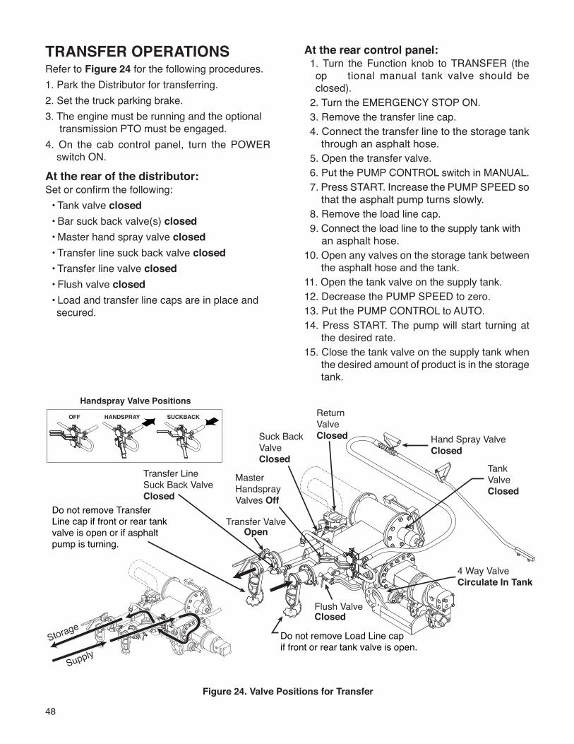
48
TRANSFER OPERATIONSRefer to Figure 24 for the following procedures.1. Park the Distributor for transferring.2. Set the truck parking brake.3. The engine must be running and the optional
transmission PTO must be engaged.4. On the cab control panel, turn the POWER
switch ON.
At the rear of the distributor:Set or confirm the following: • Tank valve closed • Bar suck back valve(s) closed • Master hand spray valve closed • Transfer line suck back valve closed • Transfer line valve closed • Flush valve closed • Load and transfer line caps are in place and
secured.
Figure 24. Valve Positions for Transfer
At the rear control panel: 1. Turn the Function knob to TRANSFER (the
op tional manual tank valve should be closed).
2. Turn the EMERGENCY STOP ON. 3. Remove the transfer line cap.4. Connect the transfer line to the storage tank
through an asphalt hose. 5. Open the transfer valve. 6. Put the PUMP CONTROL switch in MANUAL.7. Press START. Increase the PUMP SPEED so
that the asphalt pump turns slowly. 8. Remove the load line cap. 9. Connect the load line to the supply tank with
an asphalt hose.10. Open any valves on the storage tank between
the asphalt hose and the tank.11. Open the tank valve on the supply tank.12. Decrease the PUMP SPEED to zero.13. Put the PUMP CONTROL to AUTO.14. Press START. The pump will start turning at
the desired rate.15. Close the tank valve on the supply tank when
the desired amount of product is in the storage tank.
OFF HANDSPRAY SUCKBACK
Handspray Valve PositionsReturn Valve Closed Hand Spray Valve
Closed
4 Way ValveCirculate In Tank
Tank ValveClosed
Master Handspray Valves Off
Transfer ValveOpen
Transfer Line Suck Back Valve Closed
Flush ValveClosed
Suck Back Valve Closed
Do not remove Transfer Line cap if front or rear tankvalve is open or if asphalt pump is turning.
Do not remove Load Line cap if front or rear tank valve is open.
SupplyStorage
49
16. At the supply tank, carefully open the bleeder valve or break the hose connection until a strong vacuum is heard. It may be necessary to reduce the pump speed in order to overcome the pump vacuum when breaking the hose connection. Elevating the hose above the load line connection will allow maximum drainage of the hose.
17. Disconnect the hose from the load line.18. Replace the load line cap and secure.19. Put the PUMP CONTROL to MANUAL to stop
the pump and then put it back to AUTO.20. Close the valve at the storage tank.21. Close the transfer valve.22. Turn the Function knob to SUCK BACK (the
optional manual tank valve should be closed.23. Open the transfer suck back valve.24. Press START.25. At the storage tank, carefully open the bleeder
valve or break the hose connection until a strong vacuum is heard. It may be necessary to reduce the pump speed in order to overcome the pump vacuum when breaking the hose connection. Elevating the hose above the load line connection will allow maximum drainage of the hose.
26. Disconnect the hose from the transfer line.27. Replace transfer line cap and secure.
28. Close the transfer line suck back valve.29. It may be necessary to flush the pump before
doing the next step.30. To stop the pump in MANUAL control select
AUTO control. To stop the pump in AUTO con-trol with the PUMP SPEED knob fully counter clockwise select MANUAL control.
NOTE: The pump can be stopped and the automatic tank valve can be closed immediately at any time during operation by turning the EMERGENCY STOP switch OFF. Before turning the EMERGENCY STOP switch back ON, turn the PUMP SPEED to zero to prevent the pump from turning.
WARNINGTo prevent burns, always wear insulated gloves when handling spray bar sections or hoses.
WARNINGSuckback of the storage tank line will put material into the tank and could cause an explosion if the tank has not been fully cleaned of emulsion material.
50
Heating Asphalt w/ Propane Burners
IMPORTANTCirculating the asphalt in the tank while heating is recommended for faster heating and reduced carbon formation on the flues. Only when the asphalt pump is Frozen is it acceptable to operate the burners without circulating asphalt in the tank. However, if the asphalt pump is frozen, carefully apply heat to the pump and start circulating the material as soon as possible.
WARNING1. Residual fuel in Propane burners will support a flame for several minutes after the fuel flow has been shut off. After using Propane burners, confirm that all flame has been extinguished before attempting any operation that could release flammable vapors. Failure to ensure that the flame is completely extinguished could result in an explosion or fire that can cause injury or death.2. Position unit broadside to wind whenever possible to prevent volatile fumes from drifting toward burners3. Flues MUST be covered by a minimum of 6 inches (150mm) of material when the burners are in operation.4. Do not remove material from tank in any manner when the burners are in operation.5. Do not drive unit when burners are operating.6. Do not operate burners if tank is damaged or leaking.7. When burners go out, allow flues to ventilate for several minutes before relighting burners.8. Do not heat material beyond the manu- facturers recommended temperature.9. Do not heat material over 200ºF (95ºC) if moisture is present in tank.
11. Always shut off burners using the main shutoff valve on the supply tank.12. To prevent possible burns, always use a torch to light the burners. never attempt to light the burners with a match or pocket lighter.13. Light inside burner first. Do not reach across a lighted burner to relight inside burner.14. Check overflow tube for restrictions.15. When heating, temperatures within the tank can vary. Shut the burners off when the thermometer reaches a reading 10ºF lower than the desired temperature. Continue to circulate & monitor temperature until temperature stabilizes. Add remaining heat by operating burners for short periods, monitoring stabilized temperature after each period.16. Always have a dry chemical type fire extinguisher available and in good condition.
IMPORTANTCalibration of thermometers should be verified to be within + 2% of full scale reading annually.Certification can be accomplished by a qualified laboratory or by comparing stabilized dial readings to the pencil thermometer reading. Replace any thermometer that does not meet the +2% accuracy requirement.
WARNING (cont)
Propane Requirements Use only liquid withdrawal type supply tanks foryour propane burners. Two types of propane supply tanks are avail-able: tanks for liquid type burners and tanks for vapor type burners. the propane burners on yourEtnyre Distributor require a supply tank for liquidtype burners. Liquid type burners will operate from a vapor withdrawal tank, however the amount of heat delivered will be dramatically reduced, and the life of the burner will be shortened.
Heating Product in Distributors
10. To prevent possible burns from material overflow, allow sufficient space in tank for expansion of material when heating.
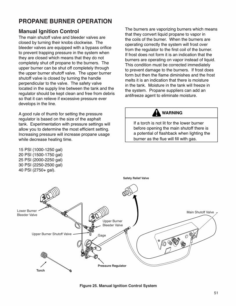
51
PROPANE BURNER OPERATIONManual Ignition ControlThe main shutoff valve and bleeder valves are closed by turning their knobs clockwise. The bleeder valves are equipped with a bypass orifice to prevent trapping pressure in the system when they are closed which means that they do not completely shut off propane to the burners. The upper burner can be shut off completely through the upper burner shutoff valve. The upper burner shutoff valve is closed by turning the handle perpendicular to the valve. The safety valve located in the supply line between the tank and the regulator should be kept clean and free from debris so that it can relieve if excessive pressure ever develops in the line.
A good rule of thumb for setting the pressure regulator is based on the size of the asphalt tank. Experimentation with pressure settings will allow you to determine the most efficient setting. Increasing pressure will increase propane usage while decrease heating time.
15 PSI (1000-1250 gal)20 PSI (1500-1750 gal)25 PSI (2000-2250 gal)30 PSI (2250-2500 gal)40 PSI (2750+ gal).
Figure 25. Manual Ignition Control System
The burners are vaporizing burners which means that they convert liquid propane to vapor in the coils of the burner. When the burners are operating correctly the system will frost over from the regulator to the first coil of the burner. If frost does not form it is an indication that the burners are operating on vapor instead of liquid. This condition must be corrected immediately to prevent damage to the burners. If frost does form but then the flame diminishes and the frost melts it is an indication that there is moisture in the tank. Moisture in the tank will freeze in the system. Propane suppliers can add an antifreeze agent to eliminate moisture.
WARNING
If a torch is not lit for the lower burner before opening the main shutoff there is a potential of flashback when lighting the burner as the flue will fill with gas.
Safety Relief Valve
TorchPressure Regulator
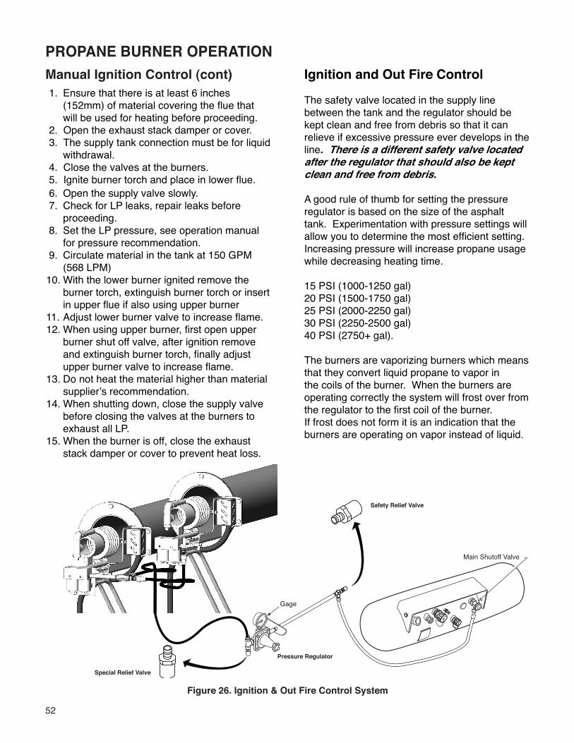
52
1. Ensure that there is at least 6 inches (152mm) of material covering the flue that will be used for heating before proceeding.
2. Open the exhaust stack damper or cover. 3. The supply tank connection must be for liquid
withdrawal. 4. Close the valves at the burners. 5. Ignite burner torch and place in lower flue. 6. Open the supply valve slowly. 7. Check for LP leaks, repair leaks before
proceeding. 8. Set the LP pressure, see operation manual
for pressure recommendation. 9. Circulate material in the tank at 150 GPM
(568 LPM)10. With the lower burner ignited remove the
burner torch, extinguish burner torch or insert in upper flue if also using upper burner
11. Adjust lower burner valve to increase flame.12. When using upper burner, first open upper
burner shut off valve, after ignition remove and extinguish burner torch, finally adjust upper burner valve to increase flame.
13. Do not heat the material higher than material supplier’s recommendation.
14. When shutting down, close the supply valve before closing the valves at the burners to exhaust all LP.
15. When the burner is off, close the exhaust stack damper or cover to prevent heat loss.
Manual Ignition Control (cont)
Figure 26. Ignition & Out Fire Control System
Ignition and Out Fire Control
The safety valve located in the supply line between the tank and the regulator should be kept clean and free from debris so that it can relieve if excessive pressure ever develops in the line. There is a different safety valve located after the regulator that should also be kept clean and free from debris.
A good rule of thumb for setting the pressure regulator is based on the size of the asphalt tank. Experimentation with pressure settings will allow you to determine the most efficient setting. Increasing pressure will increase propane usage while decreasing heating time.
15 PSI (1000-1250 gal)20 PSI (1500-1750 gal)25 PSI (2000-2250 gal)30 PSI (2250-2500 gal)40 PSI (2750+ gal).
The burners are vaporizing burners which means that they convert liquid propane to vapor in the coils of the burner. When the burners are operating correctly the system will frost over from the regulator to the first coil of the burner. If frost does not form it is an indication that the burners are operating on vapor instead of liquid.
PROPANE BURNER OPERATION
Pressure Regulator
Special Relief Valve
Safety Relief Valve
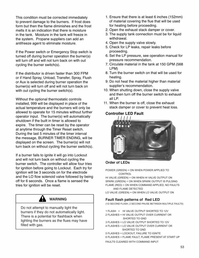
53
This condition must be corrected immediately to prevent damage to the burners. If frost does form but then the flame diminishes and the frost melts it is an indication that there is moisture in the tank. Moisture in the tank will freeze in the system. Propane suppliers can add an antifreeze agent to eliminate moisture.
If the Power switch or Emergency Stop switch is turned off during burner operation the burner(s) will turn off and will not turn back on with out cycling the burner switch(s).
If the distributor is driven faster than 300 FPM or if Hand Spray, Unload, Transfer, Spray, Flush or Aux is selected during burner operation the burner(s) will turn off and will not turn back on with out cycling the burner switch(s).
Without the optional thermostatic controls installed, 999 will be displayed in place of the actual temperature and the burners will only be allowed to operate for 15 minutes without further operator input. The burner(s) will automatically shutdown if the built in timer is allowed to expire. The timer can be reset by the operator at anytime through the Timer Reset switch. During the last 5 minutes of the timer interval the message, BURNER TIMER ENDING, will be displayed on the screen. The burner(s) will not turn back on without cycling the burner switch(s).
If a burner fails to ignite it will go into Lockout and will not turn back on without cycling the burner switch. The controller will allow four tries for ignition before going to Lockout. Each try for ignition will be 3 seconds on for the electrode and the LO flow solenoid valve followed by being off for 6 seconds. Once a flame is sensed the tries for ignition will be reset.
Order of LEDs
POWER (GREEN) = ON WHEN POWER APPLIED TO
CONTROL
HI VALVE (GREEN) = ON WHEN HI VALVE OUTPUT ON
SPARK (GREEN) = ON WHEN SPARK OUTPUT IS PULSING
FLAME (RED) = ON WHEN COMMAND APPLIED, NO FAULTS
AND FLAME DETECTED
LO VALVE (GREEN) = ON WHEN LO VALVE OUTPUT ON
Fault flash patterns of Red LED (1/2 SECOND FLASH, 2 SECOND PAUSE BETWEEN MULTIPLE FAULTS)
1 FLASH = HI VALVE OUTPUT SHORTED TO 12V
2 FLASHES = HI VALVE OUTPUT OVER CURRENT OR
SHORTED TO GND
3 FLASHES = LO VALVE OUTPUT SHORTED TO 12V
4 FLASHES = LO VALVE OUTPUT OVER CURRENT OR
SHORTED TO GND
5 FLASHES = LOCKOUT, FAILURE TO IGNITE
6 FLASHES = FLAME FAULT, FLAME PRESENT AT START UP
FAULTS CLEARED WITH COMMAND INPUT
WARNING
Do not attempt to manually light the burners if they do not automatically light. There is a potential for flashback when lighting the burners as the flues may have filled with gas.
Controller LED Fault
1. Ensure that there is at least 6 inches (152mm) of material covering the flue that will be used for heating before proceeding. 2. Open the exhaust stack damper or cover. 3. The supply tank connection must be for liquid
withdrawal. 4. Open the supply valve slowly. 5. Check for LP leaks, repair leaks before
proceeding. 6. Set the LP pressure, see operation manual for
pressure recommendation. 7. Circulate material in the tank at 150 GPM (568
LPM) 8. Turn the burner switch on that will be used for
heating. 9. Do not heat the material higher than material
supplier’s recommendation.10. When shutting down, close the supply valve
and then turn off the burner switch to exhaust all LP.
11. When the burner is off, close the exhaust stack damper or cover to prevent heat loss.
54
PROPANE BURNER OPERATIONThermostatic ControlAfter setting the target temperature in the display the burners can be operated following the instructions and precautions for Operation with Ignition and Out Fire Control. The target temperature, which can be changed in 5 degree increments, is reset to 95ºF or 35ºC when the system power is turned on. The timer will allow 15 minute heating intervals if temperature sender is out of range, 999 is displayed in place of the actual temperature, or 60 minute intervals otherwise.
The timer can be reset by the operator at any time through the Timer Reset switch. During the last 5 minutes of the timer interval the message, BURNER TIMER ENDING, will be displayed on the screen. The burner(s) will also turn off if the temperature sender goes out of range during burner operation. In all conditions, the burner(s) will not turn back on without cycling the burner switch(s).
The thermostatic control temperature is measured at the bottom of the tank.
The temperature in the bottom of the tank may be significantly colder than the top of the tank or around the flues.
Manually monitor the tank temperature care-fully to avoid overheating if initially the load could not be circulated or was known to be cold or frozen.
WARNING
55
WARNINGIMPORTANTCirculating the asphalt in the tank while heating is recommended for faster heating and reduced carbon formation on the flues. Only when the asphalt pump is Frozen is it acceptable to operate the burners without circulating asphalt in the tank. However, if the asphalt pump is frozen, carefully apply heat to the pump and start circulating the material as soon as possible.
1. Position unit broadside to wind whenever possible to prevent volatile fumes from drifting toward burners 2. Flues MUST be covered by a minimum of 6 inches (150mm) of material when the burners are in operation. 3. Do not remove material from tank in any manner when the burners are in operation. 4. Do not drive unit when burners are operating. 5. Do not operate burners if tank is damaged or leaking. 6. When burners go out, allow flues to ventilate for several minutes before relighting burners. 7. Do not heat material beyond the manu- facturers recommended temperature. 8. Do not heat material over 200ºF (95ºC) if moisture is present in tank. 9. To prevent possible burns from material overflow, allow sufficient space in tank for expansion of material when heating.10. Check overflow tube for restrictions.11. There must be at least 6 inches of material covering the entire length of the upper flue before the second burner can be lit.12. When heating, temperatures within the tank can vary. Shut the burners off when the thermometer reaches a reading 10ºF lower than the desired temperature. Continue to circulate & monitor temperature until temperature stabilizes. Add remaining heat by operating burners for short periods, monitoring stabilized temperature after each period.13. Always have a dry chemical type fire extinguisher available and in good condition.
Calibration of thermometers should be verified to be within + 2% of full scale reading annually.Certification can be accomplished by a qualified laboratory or by comparing stabilized dial readings to the pencil thermometer reading. Replace any thermometer that does not meet the +2% accuracy requirement.
Heating Product in DistributorsHeating Asphalt w/ Fuel Oil Burners
IMPORTANT
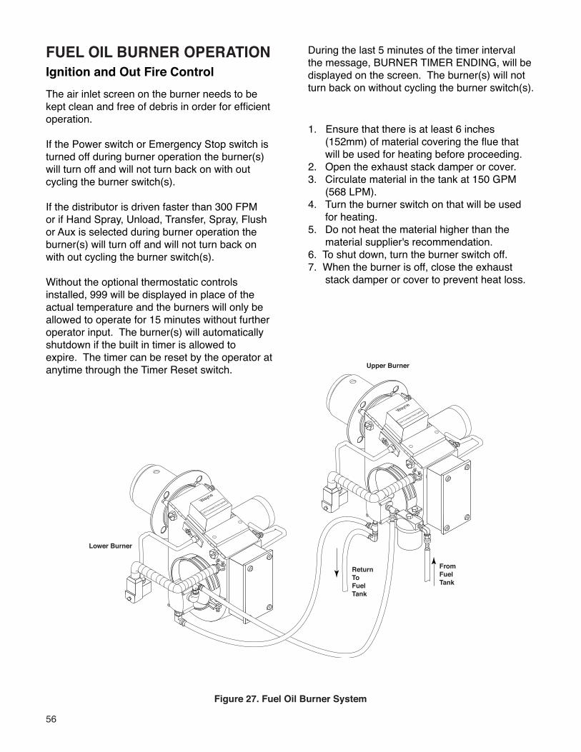
56
FUEL OIL BURNER OPERATIONIgnition and Out Fire Control
Wayne
12V Constant Duty Ignitor
Wayne
12V Constant Duty Ignitor
From�Fuel�Tank
Return�To�Fuel�Tank
Upper Burner
Lower Burner
The air inlet screen on the burner needs to be kept clean and free of debris in order for efficient operation.
If the Power switch or Emergency Stop switch is turned off during burner operation the burner(s) will turn off and will not turn back on with out cycling the burner switch(s).
If the distributor is driven faster than 300 FPM or if Hand Spray, Unload, Transfer, Spray, Flush or Aux is selected during burner operation the burner(s) will turn off and will not turn back on with out cycling the burner switch(s).
Without the optional thermostatic controls installed, 999 will be displayed in place of the actual temperature and the burners will only be allowed to operate for 15 minutes without further operator input. The burner(s) will automatically shutdown if the built in timer is allowed to expire. The timer can be reset by the operator at anytime through the Timer Reset switch.
Figure 27. Fuel Oil Burner System
During the last 5 minutes of the timer interval the message, BURNER TIMER ENDING, will be displayed on the screen. The burner(s) will not turn back on without cycling the burner switch(s).
1. Ensure that there is at least 6 inches (152mm) of material covering the flue that will be used for heating before proceeding.
2. Open the exhaust stack damper or cover.3. Circulate material in the tank at 150 GPM (568 LPM).4. Turn the burner switch on that will be used
for heating. 5. Do not heat the material higher than the
material supplier's recommendation.6. To shut down, turn the burner switch off.7. When the burner is off, close the exhaust
stack damper or cover to prevent heat loss.
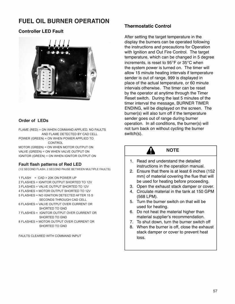
57
Order of LEDs
FLAME (RED) = ON WHEN COMMAND APPLIED, NO FAULTS
AND FLAME DETECTED BY CAD CELL
POWER (GREEN) = ON WHEN POWER APPLIED TO
CONTROL
MOTOR (GREEN) = ON WHEN MOTOR OUTPUT ON
VALVE (GREEN) = ON WHEN VALVE OUTPUT ON
IGNITOR (GREEN) = ON WHEN IGNITOR OUTPUT ON
Fault flash patterns of Red LED
(1/2 SECOND FLASH, 2 SECOND PAUSE BETWEEN MULTIPLE FAULTS)
1 FLASH = CAD > 20K ON POWER UP
2 FLASHES = IGNITOR OUTPUT SHORTED TO 12V
3 FLASHES = VALVE OUTPUT SHORTED TO 12V
4 FLASHES = MOTOR OUTPUT SHORTED TO 12V
5 FLASHES = NO IGNITION DETECTED AFTER 15 S
SECONDS THROUGH CAD CELL
6 FLASHES = VALVE OUTPUT OVER CURRENT OR
SHORTED TO GND
7 FLASHES = IGNITOR OUTPUT OVER CURRENT OR
SHORTED TO GND
8 FLASHES = MOTOR OUTPUT OVER CURRENT OR
SHORTED TO GND
FAULTS CLEARED WITH COMMAND INPUT
Thermostatic Control
After setting the target temperature in the display the burners can be operated following the instructions and precautions for Operation with Ignition and Out Fire Control. The target temperature, which can be changed in 5 degree increments, is reset to 95°F or 35°C when the system power is turned on. The timer will allow 15 minute heating intervals if temperature sender is out of range, 999 is displayed in place of the actual temperature, or 60 minute intervals otherwise. The timer can be reset by the operator at anytime through the Timer Reset switch. During the last 5 minutes of the timer interval the message, BURNER TIMER ENDING, will be displayed on the screen. The burner(s) will also turn off if the temperature sender goes out of range during burner operation. In all conditions, the burner(s) will not turn back on without cycling the burner switch(s).
NOTE
Controller LED Fault
FUEL OIL BURNER OPERATION
1. Read and understand the detailed instructions in the operation manual.
2. Ensure that there is at least 6 inches (152 mm) of material covering the flue that will be used for heating before proceeding.
3. Open the exhaust stack damper or cover.4. Circulate material in the tank at 150 GPM
(568 LPM).5. Turn the burner switch on that will be
used for heating.6. Do not heat the material higher than
material supplier’s recommendation.7. To shut down, turn the burner switch off8. When the burner is off, close the exhaust
stack damper or cover to prevent heat loss.
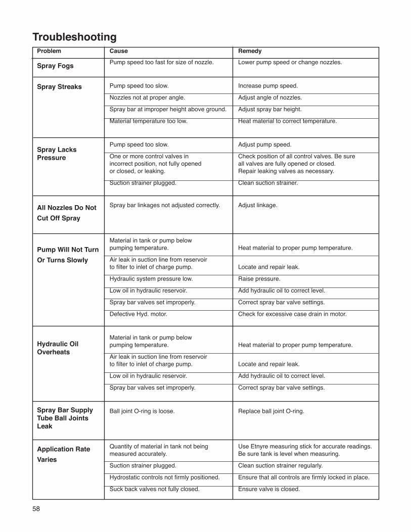
58
Troubleshooting Problem Cause Remedy
Pump speed too fast for size of nozzle. Lower pump speed or change nozzles.
Pump speed too slow. Increase pump speed.
Nozzles not at proper angle. Adjust angle of nozzles.
Spray bar at improper height above ground. Adjust spray bar height.
Material temperature too low. Heat material to correct temperature.
Pump speed too slow. Adjust pump speed.
One or more control valves in Check position of all control valves. Be sure incorrect position, not fully opened all valves are fully opened or closed. or closed, or leaking. Repair leaking valves as necessary.
Suction strainer plugged. Clean suction strainer.
Spray bar linkages not adjusted correctly. Adjust linkage.
Material in tank or pump below pumping temperature. Heat material to proper pump temperature.
Air leak in suction line from reservoir to filter to inlet of charge pump. Locate and repair leak.
Hydraulic system pressure low. Raise pressure.
Low oil in hydraulic reservoir. Add hydraulic oil to correct level.
Spray bar valves set improperly. Correct spray bar valve settings.
Defective Hyd. motor. Check for excessive case drain in motor.
Material in tank or pump below pumping temperature. Heat material to proper pump temperature.
Air leak in suction line from reservoir to filter to inlet of charge pump. Locate and repair leak.
Low oil in hydraulic reservoir. Add hydraulic oil to correct level.
Spray bar valves set improperly. Correct spray bar valve settings.
Ball joint O-ring is loose. Replace ball joint O-ring.
Quantity of material in tank not being Use Etnyre measuring stick for accurate readings. measured accurately. Be sure tank is level when measuring.
Suction strainer plugged. Clean suction strainer regularly.
Hydrostatic controls not firmly positioned. Ensure that all controls are firmly locked in place.
Suck back valves not fully closed. Ensure valve is closed.
Spray Fogs
Spray Streaks
Spray Lacks Pressure
All Nozzles Do NotCut Off Spray
Pump Will Not TurnOr Turns Slowly
Hydraulic Oil Overheats
Spray Bar SupplyTube Ball JointsLeak
Application RateVaries
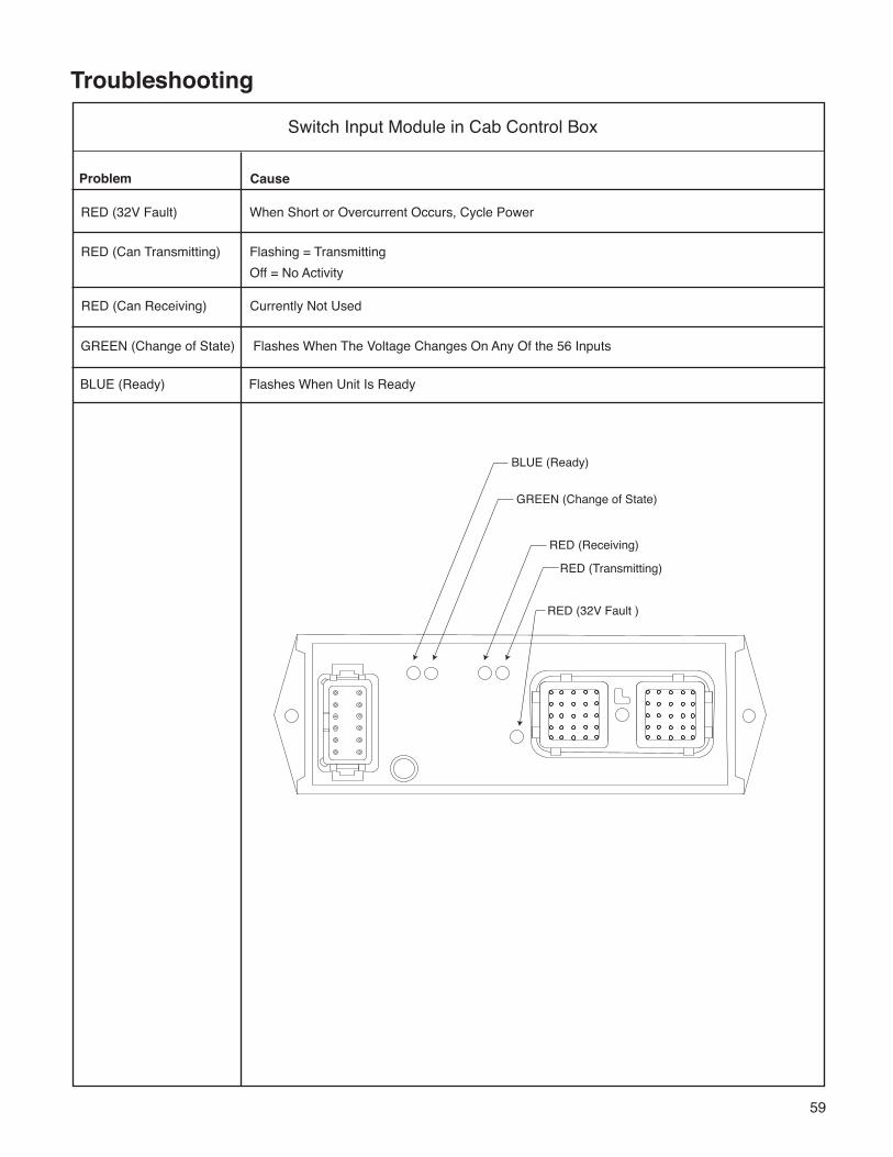
59
Troubleshooting
Cause
RED (32V Fault) When Short or Overcurrent Occurs, Cycle Power
RED (Can Transmitting) Flashing = Transmitting Off = No Activity
RED (Can Receiving) Currently Not Used
GREEN (Change of State) Flashes When The Voltage Changes On Any Of the 56 Inputs
BLUE (Ready) Flashes When Unit Is Ready
Problem
Switch Input Module in Cab Control Box
BLUE (Ready)
GREEN (Change of State)
RED (Receiving)
RED (Transmitting)
RED (32V Fault )
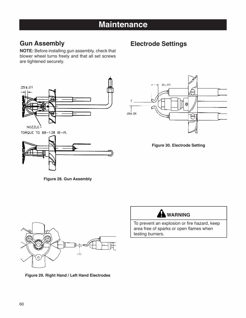
60
Figure 30. Electrode Setting
WARNINGTo prevent an explosion or fire hazard, keep area free of sparks or open flames when testing burners.
Gun AssemblyNOTE: Before installing gun assembly, check that blower wheel turns freely and that all set screws are tightened securely.
Figure 28. Gun Assembly
Figure 29. Right Hand / Left Hand Electrodes
Maintenance
Electrode Settings
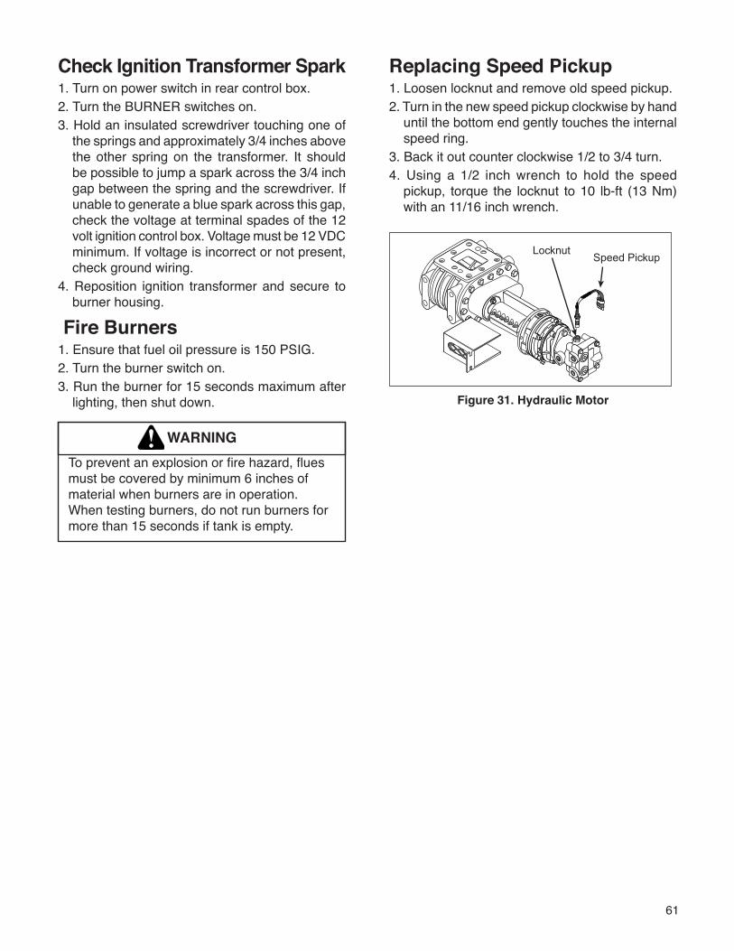
61
Replacing Speed Pickup1. Loosen locknut and remove old speed pickup.2. Turn in the new speed pickup clockwise by hand
until the bottom end gently touches the internal speed ring.
3. Back it out counter clockwise 1/2 to 3/4 turn.4. Using a 1/2 inch wrench to hold the speed
pickup, torque the locknut to 10 lb-ft (13 Nm) with an 11/16 inch wrench.
Figure 31. Hydraulic Motor
Check Ignition Transformer Spark1. Turn on power switch in rear control box.2. Turn the BURNER switches on.3. Hold an insulated screwdriver touching one of
the springs and approximately 3/4 inches above the other spring on the transformer. It should be possible to jump a spark across the 3/4 inch gap between the spring and the screwdriver. If unable to generate a blue spark across this gap, check the voltage at terminal spades of the 12 volt ignition control box. Voltage must be 12 VDC minimum. If voltage is incorrect or not present, check ground wiring.
4. Reposition ignition transformer and secure to burner housing.
Fire Burners1. Ensure that fuel oil pressure is 150 PSIG.2. Turn the burner switch on.3. Run the burner for 15 seconds maximum after
lighting, then shut down.
WARNINGTo prevent an explosion or fire hazard, flues must be covered by minimum 6 inches of material when burners are in operation. When testing burners, do not run burners for more than 15 seconds if tank is empty.
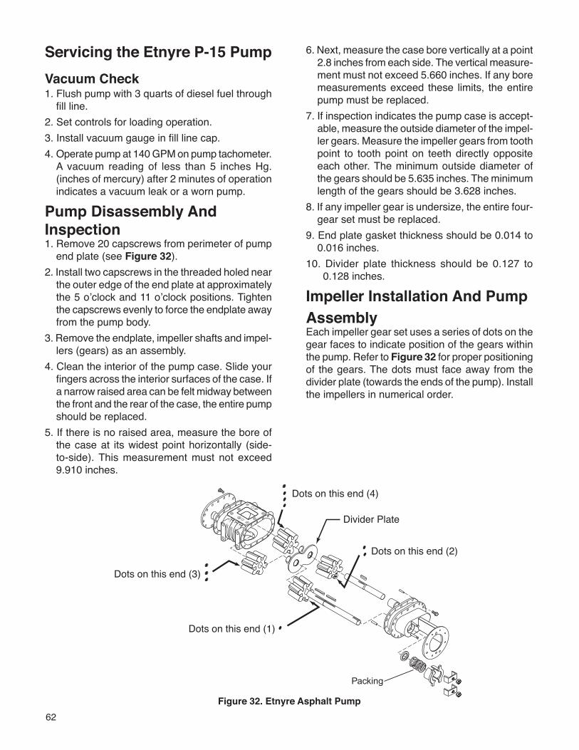
62
Servicing the Etnyre P-15 PumpVacuum Check1. Flush pump with 3 quarts of diesel fuel through
fill line.2. Set controls for loading operation.3. Install vacuum gauge in fill line cap.4. Operate pump at 140 GPM on pump tachometer.
A vacuum reading of less than 5 inches Hg. (inches of mercury) after 2 minutes of operation indicates a vacuum leak or a worn pump.
Pump Disassembly And Inspection1. Remove 20 capscrews from perimeter of pump
end plate (see Figure 32).2. Install two capscrews in the threaded holed near
the outer edge of the end plate at approximately the 5 o’clock and 11 o’clock positions. Tighten the capscrews evenly to force the endplate away from the pump body.
3. Remove the endplate, impeller shafts and impel-lers (gears) as an assembly.
4. Clean the interior of the pump case. Slide your fingers across the interior surfaces of the case. If a narrow raised area can be felt midway between the front and the rear of the case, the entire pump should be replaced.
5. If there is no raised area, measure the bore of the case at its widest point horizontally (side-to-side). This measurement must not exceed 9.910 inches.
6. Next, measure the case bore vertically at a point 2.8 inches from each side. The vertical measure-ment must not exceed 5.660 inches. If any bore measurements exceed these limits, the entire pump must be replaced.
7. If inspection indicates the pump case is accept-able, measure the outside diameter of the impel-ler gears. Measure the impeller gears from tooth point to tooth point on teeth directly opposite each other. The minimum outside diameter of the gears should be 5.635 inches. The minimum length of the gears should be 3.628 inches.
8. If any impeller gear is undersize, the entire four-gear set must be replaced.
9. End plate gasket thickness should be 0.014 to 0.016 inches.
10. Divider plate thickness should be 0.127 to 0.128 inches.
Impeller Installation And PumpAssemblyEach impeller gear set uses a series of dots on the gear faces to indicate position of the gears within the pump. Refer to Figure 32 for proper positioning of the gears. The dots must face away from the divider plate (towards the ends of the pump). Install the impellers in numerical order.
Figure 32. Etnyre Asphalt Pump
63
General Fuel Data and Heating TerminologyFuel Data Fuel Weight Per BTU Content Gallon #2 Fuel Oil 7.49 lbs 144,300 per gallon
Propane 4.20 lbs. 91,500 per gallon
Approximate Burner Fuel ConsumptionFuel Oil429,000 BTU2.97 GPH per burner(144,300 BTU per gallon)
Propane1,130,000 BTU @ 40 PSI12.34 GPH per burner(91,500 BTU per gallon)
Heating TerminologyFlash Point (Open Cup)The temperature at which a flammable liquid in an open container emits vapor that will flash when exposed to a direct flame. This temperature is lower than required for the liquid mass to ignite.
Closed Flash PointThe temperature at which a flammable liquid in a closed container emits a vapor that will flash when exposed to a direct flame. This temperature is lower than required for the liquid mass to ignite. The closed flash point is generally 30ºF lower than the open cup flash point.
Fire PointThe temperature at which a flammable liquid emits a vapor at a rate that will continue to burn after it has flashed.
Ignition Temperature (Kindling Temperature)The lowest temperature at which a combustible material will continue to burn once ignited.
ConvectionHeat transfer by a flow of a liquid or gas over a solid material. Example: Flues in asphalt tank are heated from hot gases passing through them, or, heat transfer coils in tank are heated from steam or hot oil passing through them.
ConductionHeat transfer through a solid mass by direct molecular contact. Example: Heat applied only to one end of a metal rod will be transferred throughout the entire body by molecular transfer.
64
Hydraulic Fluid RequirementsGeneral InformationThe ability of a hydrostatic transmission to maintain desired performance for the expected life depends on the quality of fluid being circulated in the units. Fluid quality can be measured in three generalcategories: lubricity, contaminants, and temperature. Obtaining satisfactory values in these three areas depends on the fluid and the circuit in which it is used.Etnyre field service experience indicates that most transmission failures result from a breakdown of fluid quality. Primary causes are solid particle contamination and overheating. Water or oil in the fluids are also significant contributors. These problems are usually the result of poor maintenance. Sometimes fluid selection can lessen the impact of unusual environmental factors.
Hydraulic Fluid RequirementsThe catalog ratings and performance data are based on operating with good quality petroleum based fluids. Premium hydraulic fluids containing high quality rust, oxidation and foam inhibitors are required. These include premium turbine oils, API CD engine oils per SAE J183, M2C33F or G automatic transmission fluid (Type F), power shift transmission fluids meeting Allison© C-3 or Caterpillar© TO-2, and certain specialty agricultural tractor fluids.Although fluids containing anti-wear additives are not necessary for satisfactory performance, when used, the fluids must possess good thermal and hydrolytic stability to prevent wear, erosion and corrosion of the internal components.Where water contamination is likely due to condensation, operation in a damp environment or frequent splashing, a fluid with outstanding hydrolytic stability is recommended. Consult the Etnyre Service Department for recommendations for these fluids. Avoiding the use of Dexron© II transmission fluids which do not meet Allison C-3 specification is recommended.
Viscosity & Temperature RequirementsThe fluid must have sufficient viscosity to maintain an oil film at the bearing surfaces. This depends on fluid selection and on operating temperature. Recommended viscosity for best life and efficiency, and minimum for intermittent and continuous operation is listed below.
Fluid Viscosity Limits For Petroleum Based Fluids
Maximum Continuous SUS (cSt) 500 (110) Optimum Viscosity SUS (cSt) 70 (13) Minimum Continuous SUS (cSt) 55 (9.0) Minimum Intermittent SUS (cSt) 47 (6.4)
Viscosity index improved (multi-viscosity) fluids may noticeably shear down in service when used in hydrostatic transmissions. This will lower the operating viscosity below the originally specified value. The lowest expected viscosity must be used when selecting fluids. Consult your fluid supplier for details on viscosity sheardown.Fluid temperature affects the viscosity of the fluid and resulting lubricity and film thickness. High temperatures can also limit seal life, as most nonmetallic seals are adversely affected by use at elevated temperatures. Also, fluids may break down or oxidize at high temperatures, reducing their lubricity and the resulting life of the unit. Cavitation is more likely at high temperature. Recommended limits for operating temperatures are tabulated below.
Fluid Temperature Limits For Petroleum Based Fluids
Continuous Limit 180ºF Intermittent Limit 220ºF
These temperature limits apply at the hottest point in the transmission, which is normally the motor case drain.Heat problems sometimes occur because of problems with one of the circuit components. A partially stuck relief valve will heat up the oil rapidly. Circuit components that have developed high internal leakage rates will contribute to heat generation.
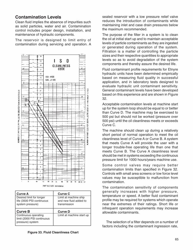
65
Contamination LevelsClean fluid implies the absence of impurities such as solid particles, water and air. Contamination control includes proper design, installation, and maintenance of hydraulic components.The reservoir is designed to limit entry of contamination during servicing and operation. A
sealed reservoir with a low pressure relief valve reduces the introduction of contaminants while maintaining inlet and case drain pressures below the maximum recommended.The purpose of the filter in a system is to clean the oil at initial start up and to maintain acceptable levels of particle contaminants as they are ingested or generated during operation of the system. Filtration is a matter of controlling the particle sizes and their respective quantities to appropriate levels so as to avoid degradation of the system components and thereby assure the desired life.Fluid contaminant profile requirements for Etnyre hydraulic units have been determined empirically based on measuring fluid quality in successful application, and in laboratory tests designed to evaluate hydraulic unit contaminant sensitivity. General contaminant levels have been developed based on this experience and are shown in Figure 32.Acceptable contamination levels at machine start up for the system loop should be equal to or better than Curve D. The machine may be exercised to 500 psi but should not be worked (pressure over 500 psi) until the oil cleanliness meets or exceeds Curve C.The machine should clean up during a relatively short period of normal operation to meet the oil cleanliness level of Curve A or Curve B. A system that meets Curve A will provide the user with a longer trouble-free operating life than one that meets Curve B. The Curve A cleanliness level should be met in systems exceeding the continuous pressure limit for 1000 hours/years machine use.Some control valves may require better contamination limits than specified in Figure 32. Controls with small area screens or low force level values may be susceptible to malfunction from contamination.The contamination sensitivity of components generally increases with higher pressure, temperature or speed. A better fluid contaminant profile may be required for systems which operate near the extremes of their ratings. Short life or infrequent operation requirements may increase allowable contaminants.
Figure 33. Fluid Cleanliness Chart
Curve A Curve CDesired limit for longer Limit at machine shiplife (3500 PSI continuous and new fluid added tosystem pressure) transmission
Curve B Curve DContinuous operating Limit at machine start uplimit (2000 PSI continuouspressure) system The selection of a filter depends on a number of
factors including the contaminant ingression rate,
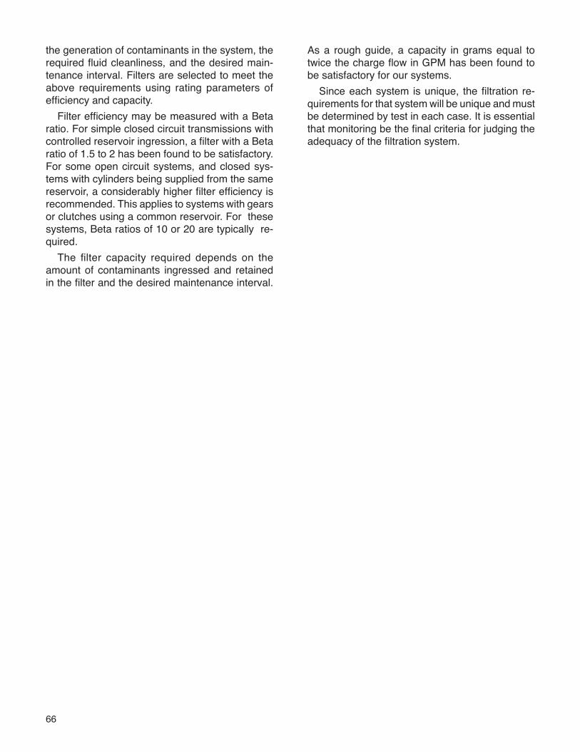
66
the generation of contaminants in the system, the required fluid cleanliness, and the desired main-tenance interval. Filters are selected to meet the above requirements using rating parameters of efficiency and capacity.
Filter efficiency may be measured with a Beta ratio. For simple closed circuit transmissions with controlled reservoir ingression, a filter with a Beta ratio of 1.5 to 2 has been found to be satisfactory. For some open circuit systems, and closed sys-tems with cylinders being supplied from the same reservoir, a considerably higher filter efficiency is recommended. This applies to systems with gears or clutches using a common reservoir. For these systems, Beta ratios of 10 or 20 are typically re-quired.
The filter capacity required depends on the amount of contaminants ingressed and retained in the filter and the desired maintenance interval.
As a rough guide, a capacity in grams equal to twice the charge flow in GPM has been found to be satisfactory for our systems.
Since each system is unique, the filtration re-quirements for that system will be unique and must be determined by test in each case. It is essential that monitoring be the final criteria for judging the adequacy of the filtration system.
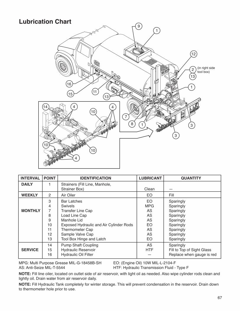
67
INTERVAL POINT IDENTIFICATION LUBRICANT QUANTITYDAILY 1 Strainers (Fill Line, Manhole, Strainer Box) Clean —WEEKLY 2 Air Oiler EO Fill 3 Bar Latches EO Sparingly 4 Swivels MPG SparinglyMONTHLY 7 Transfer Line Cap AS Sparingly 8 Load Line Cap AS Sparingly 9 Manhole Lid AS Sparingly 10 Exposed Hydraulic and Air Cylinder Rods EO Sparingly 11 Thermometer Cap AS Sparingly 12 Sample Valve Cap AS Sparingly 13 Tool Box Hinge and Latch EO Sparingly 14 Pump Shaft Coupling AS SparinglySERVICE 15 Hydraulic Reservoir HTF Fill to Top of Sight Glass 16 Hydraulic Oil Filter — Replace when gauge is red
MPG: Multi Purpose Grease MIL-G-18458B-SH EO: (Engine Oil) 10W MIL-L-2104-FAS: Anti-Seize MIL-T-5544 HTF: Hydraulic Transmission Fluid - Type FNOTE: Fill line oiler, located on outlet side of air reservoir, with light oil as needed. Also wipe cylinder rods clean and lightly oil. Drain water from air reservoir daily.NOTE: Fill Hydraulic Tank completely for winter storage. This will prevent condensation in the reservoir. Drain down to thermometer hole prior to use.
Lubrication Chart
20
91
12
15 1311
16
213
1
18
7
(in right sidetool box)
4
10
1014 4
10
3
3
4
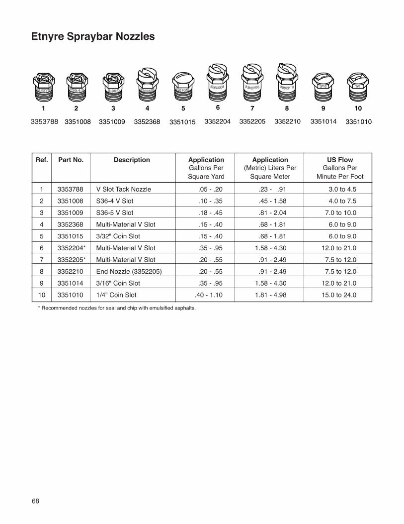
68
Etnyre Spraybar Nozzles
Ref. Part No. Description Application Application US Flow Gallons Per (Metric) Liters Per Gallons Per Square Yard Square Meter Minute Per Foot
1 3353788 V Slot Tack Nozzle .05 - .20 .23 - .91 3.0 to 4.5 2 3351008 S36-4 V Slot .10 - .35 .45 - 1.58 4.0 to 7.5 3 3351009 S36-5 V Slot .18 - .45 .81 - 2.04 7.0 to 10.0 4 3352368 Multi-Material V Slot .15 - .40 .68 - 1.81 6.0 to 9.0 5 3351015 3/32" Coin Slot .15 - .40 .68 - 1.81 6.0 to 9.0 6 3352204* Multi-Material V Slot .35 - .95 1.58 - 4.30 12.0 to 21.0 7 3352205* Multi-Material V Slot .20 - .55 .91 - 2.49 7.5 to 12.0 8 3352210 End Nozzle (3352205) .20 - .55 .91 - 2.49 7.5 to 12.0 9 3351014 3/16" Coin Slot .35 - .95 1.58 - 4.30 12.0 to 21.010 3351010 1/4" Coin Slot .40 - 1.10 1.81 - 4.98 15.0 to 24.0
* Recommended nozzles for seal and chip with emulsified asphalts.
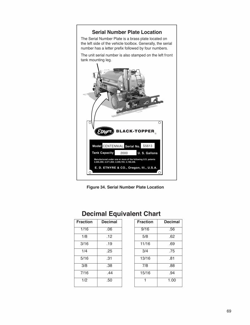
69
Figure 34. Serial Number Plate Location
Serial Number Plate Location
Model
Tank Capacity U. S. Gallons
Serial No.
E. D. ETNYRE & CO., Oregon, Ill., U.S.A.
Manufactured under one or more of the following U.S. patents2,505,390; 2,571,850; 2,599,704; 3,198,548.
CENTENNIAL S5613
2000
Serial Number Plate LocationThe Serial Number Plate is a brass plate located on the left side of the vehicle toolbox. Generally, the serial number has a letter prefix followed by four numbers.The unit serial number is also stamped on the left front tank mounting leg.
Decimal Equivalent Chart Fraction Decimal Fraction Decimal 1/16 .06 9/16 .56 1/8 .12 5/8 .62 3/16 .19 11/16 .69 1/4 .25 3/4 .75 5/16 .31 13/16 .81 3/8 .38 7/8 .88 7/16 .44 15/16 .94 1/2 .50 1 1.00
Something Wrong with this manual?If you find inaccurate or confusing information in this manual, or just have a suggestion for improvement, please let us know. Mail or FAX this form to us at: E. D. ETNYRE & CO. 1333 S. Daysville Rd. Oregon, Illinois 61061 • Fax: 800-521-1107 • www.etnyre.com Attn: Service Manager
Recommended changes from: ___________________________________
Address ________________________________________
City, State, Zip ________________________________________
Phone ________________________________________
Date Sent ________________________________________
Manual Number (upper right corner of front cover) _________________________________________
Manual Title ______________________________________________________________
Explain the problem in the space below. Page Reference Paragraph Figure Problem (please be specific)Number Number Number Number
K-525-01