Embed Size (px)
Citation preview
M A N U A LSimrad CE33ChartSounder
183-2100-702
02181.11
Note!Insert or remove C-MAP cartridges ONLY through CHART menu or when unit is off. All electronic navigation equipment is subject to external factors beyond the control of the manufacturer. Therefore such equipment must be regarded as an aid to navigation. The prudent navigator will, for that reason, never rely on a single source for position fixing and navigation.
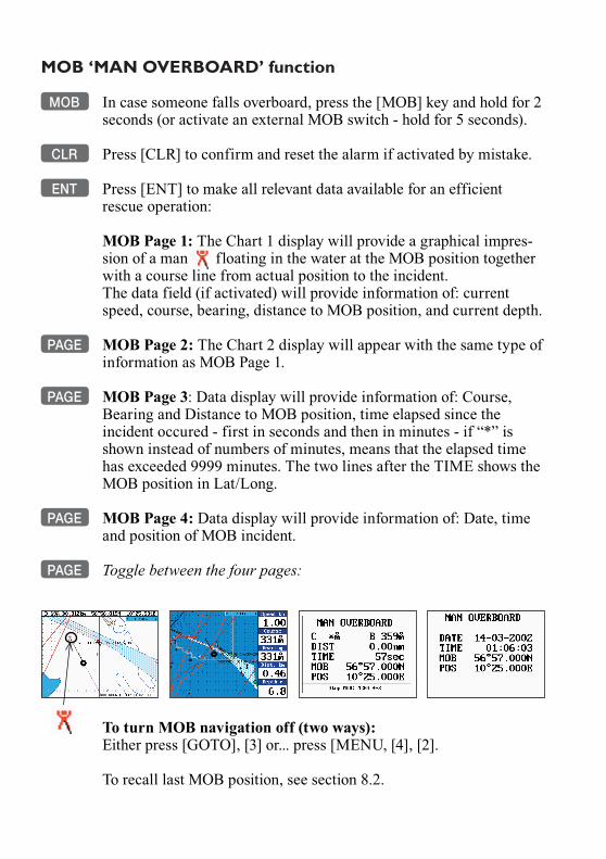
MOB ‘MAN OVERBOARD’ function MOB In case someone falls overboard, press the [MOB] key and hold for 2
seconds (or activate an external MOB switch - hold for 5 seconds).
CLR Press [CLR] to confirm and reset the alarm if activated by mistake.
ENT Press [ENT] to make all relevant data available for an efficient rescue operation:
MOB Page 1: The Chart 1 display will provide a graphical impres-sion of a man floating in the water at the MOB position together with a course line from actual position to the incident. The data field (if activated) will provide information of: current speed, course, bearing, distance to MOB position, and current depth.
PAGE MOB Page 2: The Chart 2 display will appear with the same type of information as MOB Page 1.
PAGE MOB Page 3: Data display will provide information of: Course, Bearing and Distance to MOB position, time elapsed since the incident occured - first in seconds and then in minutes - if “*” is shown instead of numbers of minutes, means that the elapsed time has exceeded 9999 minutes. The two lines after the TIME shows the MOB position in Lat/Long.
PAGE MOB Page 4: Data display will provide information of: Date, time and position of MOB incident.
PAGE Toggle between the four pages:
To turn MOB navigation off (two ways):Either press [GOTO], [3] or... press [MENU, [4], [2].
To recall last MOB position, see section 8.2.
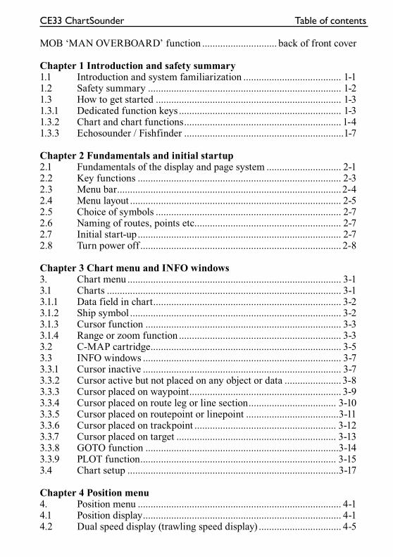
CE33 ChartSounder Table of contents
MOB ‘MAN OVERBOARD’ function ............................. back of front cover
Chapter 1 Introduction and safety summary1.1 Introduction and system familiarization ...................................... 1-11.2 Safety summary ........................................................................... 1-21.3 How to get started ........................................................................ 1-31.3.1 Dedicated function keys ............................................................... 1-31.3.2 Chart and chart functions............................................................. 1-41.3.3 Echosounder / Fishfinder ..............................................................1-7
Chapter 2 Fundamentals and initial startup2.1 Fundamentals of the display and page system ............................. 2-12.2 Key functions ............................................................................... 2-32.3 Menu bar.......................................................................................2-42.4 Menu layout .................................................................................. 2-52.5 Choice of symbols ........................................................................ 2-72.6 Naming of routes, points etc......................................................... 2-72.7 Initial start-up............................................................................... 2-72.8 Turn power off .............................................................................. 2-8
Chapter 3 Chart menu and INFO windows3. Chart menu ................................................................................... 3-13.1 Charts ........................................................................................... 3-1 3.1.1 Data field in chart......................................................................... 3-23.1.2 Ship symbol .................................................................................. 3-23.1.3 Cursor function ............................................................................ 3-33.1.4 Range or zoom function ............................................................... 3-33.2 C-MAP cartridge.......................................................................... 3-53.3 INFO windows ............................................................................. 3-73.3.1 Cursor inactive ............................................................................. 3-73.3.2 Cursor active but not placed on any object or data ...................... 3-83.3.3 Cursor placed on waypoint........................................................... 3-93.3.4 Cursor placed on route leg or line section.................................. 3-103.3.5 Cursor placed on routepoint or linepoint ....................................3-113.3.6 Cursor placed on trackpoint ....................................................... 3-123.3.7 Cursor placed on target .............................................................. 3-133.3.8 GOTO function ...........................................................................3-143.3.9 PLOT function............................................................................ 3-153.4 Chart setup ..................................................................................3-17
Chapter 4 Position menu4. Position menu ............................................................................... 4-14.1 Position display............................................................................. 4-14.2 Dual speed display (trawling speed display) ................................ 4-5
Table of contents CE33 ChartSounder
4.3 Speed, course & depth .................................................................4-64.4 Speed diagram.............................................................................. 4-74.5 Satellite status............................................................................... 4-94.6 DGPS information.......................................................................4-114.7 SDGPS information.................................................................... 4-134.7.1 Satellites in SDGPS system........................................................ 4-15
Chapter 5 Waypoint / route menu5. Waypoint / route menu ................................................................. 5-15.1 Waypoints stored in the memory ................................................. 5-15.1.1 Delete waypoints via menu .......................................................... 5-25.2 Routes stored in the memory........................................................ 5-35.2.1 Delete route via menu...................................................................5-65.2.2 Make new route from WP list ......................................................5-65.3 Route calculation .......................................................................... 5-85.4 Lines stored in the memory.......................................................... 5-95.4.1 Delete lines via menu ................................................................. 5-105.5 Start / stop track ..........................................................................5-115.6 Tracks stored in the memory...................................................... 5-125.6.1 Delete tracks via menu ............................................................... 5-135.7 Targets stored in the memory......................................................5-145.7.1 Delete target via menu................................................................ 5-15
Chapter 6 Pilot menu & navigation examples6. Pilot menu - with NAV inactive ................................................... 6-16.1 Highway display ........................................................................... 6-16.2 Pilot menu - with NAV active....................................................... 6-36.2.1 Highway display ...........................................................................6-46.2.2 Navigation setup........................................................................... 6-56.2.3 Pilot mode - Turn NAV off ........................................................... 6-56.2.4 Pilot mode - Waypoint advance.................................................... 6-56.2.5 Pilot mode - Restart to approaching point ................................... 6-56.2.6 Pilot mode - ETA & AVN ............................................................ 6-56.2.7 Pilot mode - Trim & highway ...................................................... 6-76.2.8 Pilot mode - Set & drift ................................................................6-86.3 Anchor guard................................................................................ 6-96.4 MOB alarm and navigation .......................................................... 6-96.5 Navigation examples .................................................................. 6-106.5.1 Chart / cursor navigation............................................................ 6-106.5.2 Waypoint navigation................................................................... 6-116.5.3 Route navigation......................................................................... 6-136.5.4 Track navigation ......................................................................... 6-15
CE33 ChartSounder Table of contents
Chapter 7 Echosounder operation7. Echosounder operation................................................................. 7-17.1 Echosounder menu ....................................................................... 7-27.2 Echosounder display..................................................................... 7-27.3 Bottom expansion......................................................................... 7-47.4 VRM expansion............................................................................ 7-57.5 A-scope......................................................................................... 7-67.6 Variable range marker .................................................................. 7-77.7 Depth & temperature diagram ..................................................... 7-77.8 Echosounder setup........................................................................ 7-97.9 Presentation setup........................................................................7-117.10 How the echosounder works .......................................................7-127.11 Transducer beamwidth ................................................................7-137.12 Effects of the vessel’s speed ........................................................7-14
Chapter 8 Miscellaneous menu8. Miscellaneous menu ..................................................................... 8-18.1 Wind display................................................................................. 8-18.2 MOB position ............................................................................... 8-38.3 DSC alarm (feature prepared for future DSC VHF).................... 8-38.4 Data transfer via DataCard...........................................................8-48.5 Data transfer via PC interface ......................................................8-6
Chapter 9 Setup menu9. Setup menu ................................................................................... 9-19.1 Speed alarm, units & language .................................................... 9-19.2 Interface setup, NMEA ................................................................9-49.2.1 Default sentences.......................................................................... 9-59.2.2 Description of sentences...............................................................9-69.3 Interface setup, alarm output........................................................ 9-89.4 Decca lanes................................................................................... 9-99.5 Loran C....................................................................................... 9-109.6 Display color................................................................................9-119.7 Factory settings .......................................................................... 9-13
Chapter 10 Installation and service10. Installation and service .............................................................. 10-110.1 Installation notes ........................................................................ 10-110.2 Installation of CE33 ChartSounder ............................................ 10-310.3 Location for display unit ............................................................ 10-410.4 Installation of DS33 Dual Station............................................... 10-510.4.1 Operation of DS33 Dual Station................................................. 10-510.5 Installation of antenna ................................................................ 10-610.6 Electrical connections ................................................................ 10-7
Table of contents CE33 ChartSounder
10.6.1 Power supply connections .......................................................... 10-810.6.2 Fuse............................................................................................. 10-8 10.6.3 Transducer connection ............................................................... 10-810.6.4 NMEA0183 interface connection............................................... 10-810.6.5 PC up/download via NMEA connection.................................... 10-810.7 Optional connections.................................................................. 10-910.8 Basic transducer and cable information ....................................10-1010.8.1 Transducers (optional)...............................................................10-1110.8.2 Determining the position for the transducer .............................10-1310.9 Preventive maintenance.............................................................10-1510.10 Repair and service .....................................................................10-1510.11 Troubleshooting.........................................................................10-1510.12 Specifications ............................................................................10-16
Appendix A Glossary of terms...................................................................A-1
Appendix B List of datum ..........................................................................B-1
Appendix C C-MAP attributes...................................................................C-1
Index
Declarations of conformity
International warranty
List of Simrad distributors

CE33 Introduction and safety summary Chapter 1-1
1.1 Introduction and system familiarization
Congratulations on your purchase of SIMRAD CE33 ChartSounder - a combination of the latest GPS and SDGPS receiver technology and optional built-in differential receiver for accurate positioning, plus: detailed cartogra-phy and high performance echosounder; all in a unique slim-line design with a bright 6” TFT color or monochrome display.
The CE33 chart system includes a built-in world chart for rough planning and overview. The choice of chart system best suitable for the CE33 was carefully singled out to be the C-MAP NT+ mini cards. The optional C-MAP charts are available world-wide at your local Simrad dealer.
The echosounder system with selectable frequencies will provide an impres-sion of Bottom expansion, VRM expansion, A-scope and White line.
The Global Positioning System is at this time and age the most common system used for navigation and positioning all over the world. Not only for maritime use, but also for land-based applications and aviation. The satellite-based system has been developed and is operated by the US Department of Defense in order to provide an accurate and reliable service, which include a 24-hour global coverage. The GPS system consists of approx. 24 satellites which orbit around the Earth at an altitude of approx. 20,200 km.The satellites transmit perfectly synchronized data. However, depending on the position, the signals will reach the receiver at a slightly different time. By adding the measured time difference to the known position of the satellites it is possible to calculate the ship’s position to within a few meters.
DS33 Dual Station for the CE33 is available with a 6” bright TFT color or monochrome display. The main unit and the dual station are identical in design and operation.
How to use this manual?It is a good idea if you make yourself familiar with the key functions, menu structure and rotation of pages (screens) described in chapter 2 before you start out, and then proceed with section 2.7 Initial start-up. For quick location of a certain term, please check the “Glossary of terms” and the “Index” at the back of the manual. Also, “How to get started” further on in this chapter will
Chapter 1-2 CE33 Introduction and safety summary
give you a quick introduction to some of the features you have access to in your new chart sounder.
The display examples shown in this manual are not always an exact copy of what you will see on the screen, as the presentation depends on your system configuration and choices of setup.
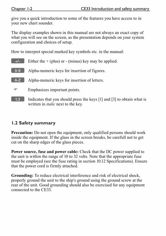
How to interpret special marked key symbols etc. in the manual:
+/- Either the + (plus) or - (minus) key may be applied.
0-9 Alpha-numeric keys for insertion of figures.
A-Z Alpha-numeric keys for insertion of letters.
� Emphasizes important points.
1,3 Indicates that you should press the keys [1] and [3] to obtain what is written in italic next to the key.
1.2 Safety summary
Precaution: Do not open the equipment, only qualified persons should work inside the equipment. If the glass in the screen breaks, be carefull not to get cut on the sharp edges of the glass pieces.
Power source, fuse and power cable: Check that the DC power supplied to the unit is within the range of 10 to 32 volts. Note that the appropriate fuse must be employed (see the fuse rating in section 10.12 Specifications). Ensure that the power cord is firmly attached.
Grounding: To reduce electrical interference and risk of electrical shock, properly ground the unit to the ship’s ground using the ground screw at the rear of the unit. Good grounding should also be exercised for any equipment connected to the CE33.
CE33 Introduction and safety summary Chapter 1-3
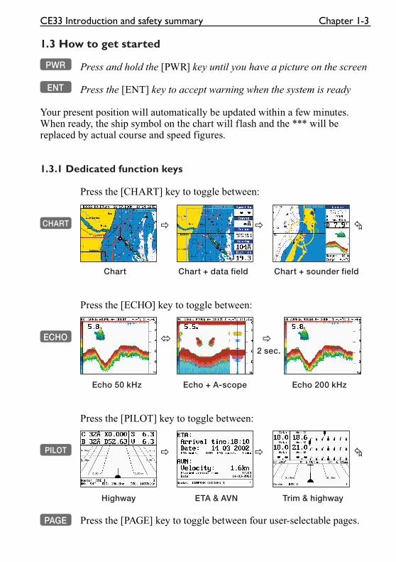
1.3 How to get started
PWR Press and hold the [PWR] key until you have a picture on the screen
ENT Press the [ENT] key to accept warning when the system is ready
Your present position will automatically be updated within a few minutes. When ready, the ship symbol on the chart will flash and the *** will be replaced by actual course and speed figures.
1.3.1 Dedicated function keys
Press the [CHART] key to toggle between:
CHART � � �
Chart Chart + data field Chart + sounder field
Press the [ECHO] key to toggle between:
ECHO � � 2 sec.
Echo 50 kHz Echo + A-scope Echo 200 kHz
Press the [PILOT] key to toggle between:
PILOT � � �
Highway ETA & AVN Trim & highway
PAGE Press the [PAGE] key to toggle between four user-selectable pages.
Chapter 1-4 CE33 Introduction and safety summary
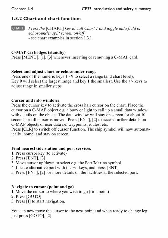
1.3.2 Chart and chart functions
CHART Press the [CHART] key to call Chart 1 and toggle data field or echosounder split screen on/off- see chart examples in section 1.3.1.
C-MAP cartridges (standby)Press [MENU], [1], [3] whenever inserting or removing a C-MAP card.
Select and adjust chart or echosounder rangePress one of the numeric keys 1 - 9 to select a range (and chart level).Key 9 will select the largest range and key 1 the smallest. Use the +/- keys to adjust range in smaller steps.
Cursor and info windowsPress the cursor key to activate the cross hair cursor on the chart. Place the cursor on a C-MAP object e.g. a buoy or light to call up a small data window with details on the object. The data window will stay on screen for about 10 seconds or till cursor is moved. Press [ENT], [2] to access further details on C-MAP objects or user data i.e. waypoints, routes, etc.Press [CLR] to switch off cursor function. The ship symbol will now automat-ically ‘home’ and stay on screen.
Find nearest tide station and port services1. Press cursor key (to activate)2. Press [ENT], [3]3. Move cursor up/down to select e.g. the Port/Marina symbol4. Locate alternative port with the +/- keys, and press [ENT]5. Press [ENT], [2] for more details on the facilities at the selected port.
Navigate to cursor (point and go)1. Move the cursor to where you wish to go (first point)2. Press [GOTO]3. Press [1] to start navigation.
You can now move the cursor to the next point and when ready to change leg, just press [GOTO], [2].
CE33 Introduction and safety summary Chapter 1-5
How to plot or insert waypoints and marks
• With cursor OFF (press [CLR])Press [PLOT] and choose from:[PLOT] Plot ship’s position as an eventmark.[2] You can insert new lat/lon figures and change the symbol’s size, type and color.[7] Plot ship’s position as target.
• With cursor activated on the chart you also have access to:[1] Plot waypoint - cursor position.[3] Insert waypoint - cursor positon. You can now insert a name and depth value. Key in a position in figures, change the symbol’s size, type and color.[7] Plot cursor position as target.
How to make a route on the chart1. Place the cursor on the position for the first routepoint.2. Press [PLOT], [5]: Make route.3. Move cursor to next destination and press [PLOT] - (repeat).4. Press [ENT] when ready to save the route. You can enter a new name for the route, change type and color for the course line.5. Press [ENT] to accept and save the route.
How to make a route from existing waypoints stored in the WP list1. Press [MENU], [3], [2] to call up the route list.2. Press [CLR] Make new route from WP list.3. Move cursor up/down to select the WP position for the first routepoint, and press [PLOT].4. Repeat point 3 to add new WP positions to the route (the last routepoint in the right column is always empty, allowing that a new final routepoint can be added later on).5. When the route is completed, press [ENT] to accept and go to Edit route.6. In the Edit route display, you can give the route a new name, change type and color for the course line, etc.7. Press [ENT] to accept changes and save the route.8. Press [MENU] to go to the route list, which will provide an overall view of the total of routes stored in the CE33.
Chapter 1-6 CE33 Introduction and safety summary
How to edit a route - rubberbanding
• To move a point:1. Place cursor on the point you wish to move.2. Press [ENT], [1], [2].3. Move cursor to new location.4. Press [ENT] to complete.
• To insert a new point:1. Place cursor on the leg where the new point is to be inserted.2. Press [ENT], [1], [2].3. Move cursor to where the new routepoint is to be placed.4. Press [ENT] to complete.
How to start waypoint navigation (two ways)
• Place cursor on the symbol of the WP you wish to go to:1. Press [GOTO], [2].2. Press [ENT] to start navigation.
• Without placing cursor on the symbol of the WP you wish to go to:1. Press [GOTO], [2].2. Use the +/- keys to select the WP you wish to go to.3. Press [ENT] to start navigation.
How to start route navigation (two ways)
• Place cursor on the routepoint you wish to go to first:1. Press [GOTO], [3].2. Select direction in route: Forward or Reverse.3. Press [ENT] to start navigation.
• Without placing cursor on the routepoint you wish to go to first:1. Press [GOTO], [3].2. Use the +/- keys to select the name of the route.3. Use the cursor to go to routepoint number, and select which one you wish to go to first by means of the +/- keys.4. Select direction in route: Forward or Reverse.5. Press [ENT] to start navigation.
CE33 Introduction and safety summary Chapter 1-7
Advance or stop navigation• Press [GOTO], [1] to advance to next point in the route.• Press [GOTO], [3] to stop navigation.
Start and stop track1. Press [MENU], [3], [5].2. Before tracking is started, you can give the track a new name, make changes to track interval, track line type and color.3. Press [ENT] to start track.4. When you wish to stop tracking, press [MENU], [3], [6], [ENT].
1.3.3 Echosounder / Fishfinder
ECHO Press the [ECHO] key to call the echosounder display- see display examples in section 1.3.1.
A-scope - Press the [ECHO] key to toggle A-scope on/off. The strength of the actual echo is indicated by both width and color intensity.
Change frequency - Press and hold the [ECHO] key for two seconds to toggle between 50 and 200 kHz.
Gain - Adjust gain with cursor left/right to just below the point where you begin to see speckles of ‘noise’ on the screen.
Range - Select range by the numeric keys 1-9, or adjust with the +/- keys. Key 0 will select Auto Range.
Echo setup (presentation) - Press [ENT] from echo display to access the setup display for either 50 or 200 kHz. Press [ENT] to confirm changes, or leave the setup without having made any changes by pressing [MENU].
Bottom expansion* - Press [MENU], [5], [3] to expand the view of the bottom in the echosounder display.
VRM expansion* - Press [MENU], [5], [4] to expand the view near the VRM in the echosounder display. Use the up/down cursor to move the VRM marker.
*Return to standard echosounder display by pressing [MENU], [5], [3] or [4].

Chapter 1-8 CE33 Introduction and safety summary
CE33 Fundamentals & initial start-up Chapter 2-1
2.1 Fundamentals of the display and page system
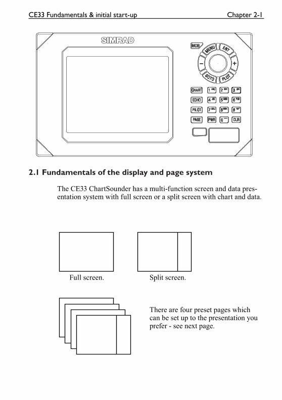
The CE33 ChartSounder has a multi-function screen and data pres-entation system with full screen or a split screen with chart and data.
Full screen. Split screen.
There are four preset pages which can be set up to the presentation you prefer - see next page.
Chapter 2-2 CE33 Fundamentals & initial start-up
Toggle between the four pre-set pages manually:
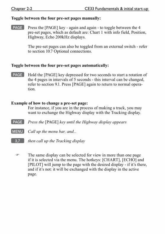
PAGE Press the [PAGE] key - again and again - to toggle between the 4 pre-set pages, which as default are: Chart 1 with info field, Position, Highway, Echo 200kHz displays.
The pre-set pages can also be toggled from an external switch - refer to section 10.7 Optional connections.
Toggle between the four pre-set pages automatically:
PAGE Hold the [PAGE] key depressed for two seconds to start a rotation of the 4 pages in intervals of 5 seconds - this interval can be changed, refer to section 9.1. Press [PAGE] again to return to normal opera-tion.
Example of how to change a pre-set page:For instance, if you are in the process of making a track, you may want to exchange the Highway display with the Tracking display.
PAGE Press the [PAGE] key until the Highway display appears
MENU Call up the menu bar, and...
3,7 then call up the Tracking display
� The same display can be selected for view in more than one page if it is selected via the menu. The hotkeys: [CHART], [ECHO] and [PILOT] will jump to the page with the desired display - if it’s there, and if it’s not: it will be exchanged with the display in the active page.
CE33 Fundamentals & initial start-up Chapter 2-3
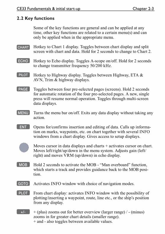
2.2 Key functions
Some of the key functions are general and can be applied at any time, other key functions are related to a certain menu(s) and can only be applied when in the appropriate menu.
CHART Hotkey to Chart 1 display. Toggles between chart display and split screen with chart and data. Hold for 2 seconds to change to Chart 2.
ECHO Hotkey to Echo display. Toggles A-scope on/off. Hold for 2 seconds to change transmitter frequency 50/200 kHz.
PILOT Hotkey to Highway display. Toggles between Highway, ETA & AVN, Trim & highway displays.
PAGE Toggles between four pre-selected pages (screens). Hold 2 seconds for automatic rotation of the four pre-selected pages. A new, single press will resume normal operation. Toggles through multi-screen data displays.
MENU Turns the menu bar on/off. Exits any data display without taking any action.
ENT Opens for/confirms insertion and editing of data. Calls up informa-tion on marks, waypoints, etc. on chart together with several INFO windows from a chart display. Gives access to setup displays.
Moves cursor in data displays and charts + activates cursor on chart. Moves left/right/up/down in the menu system. Adjusts gain (left/right) and moves VRM (up/down) in echo display.
MOB Hold 2 seconds to activate the MOB - “Man overboard” function, which starts a track and provides guidance back to the MOB posi-tion.
GOTO Activates INFO window with choice of navigation modes.
PLOT From chart display: activates INFO window with the possibility of plotting/inserting a waypoint, route, line etc., or the ship’s position from any display.
+/- + (plus) zooms out for better overview (larger range) / - (minus) zooms in for greater chart details (smaller range). + and - also toggles between available values.
Chapter 2-4 CE33 Fundamentals & initial start-up
0-9 The alpha-numeric keys inserts and selects data in data displays. Keys 1-9 are also Quick-range keys, which each represent a fixed chart range or echosounder range. Key 0 will center the cursor/ship on the chart or activate auto range in sounder mode.
CLR Turns cursor off (and centers ship) on chart display. Deletes data in enter or edit mode.
PWR Calls up a window where you can adjust the brightness in the screen, background light in keypad, and select Daylight displays, Night dis-play or custom made color palettes. Hold 2 seconds to turn the power off.
2.3 Menu bar
MENU Toggles the menu bar on/off
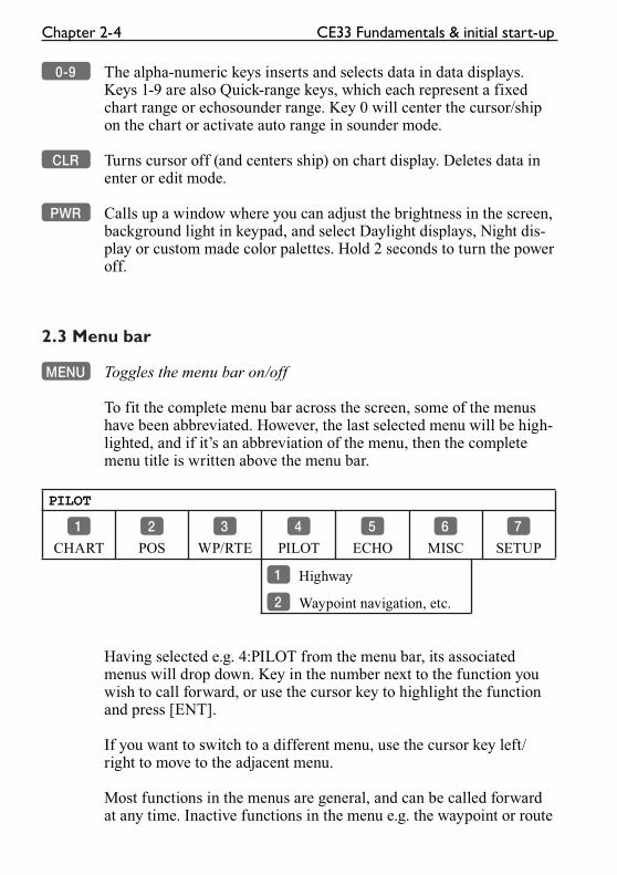
To fit the complete menu bar across the screen, some of the menus have been abbreviated. However, the last selected menu will be high-lighted, and if it’s an abbreviation of the menu, then the complete menu title is written above the menu bar.
PILOT
1
CHART
2
POS
3
WP/RTE
4
PILOT
5
ECHO
6
MISC
7
SETUP
1 Highway
2 Waypoint navigation, etc.
Having selected e.g. 4:PILOT from the menu bar, its associated menus will drop down. Key in the number next to the function you wish to call forward, or use the cursor key to highlight the function and press [ENT].
If you want to switch to a different menu, use the cursor key left/right to move to the adjacent menu.
Most functions in the menus are general, and can be called forward at any time. Inactive functions in the menu e.g. the waypoint or route
CE33 Fundamentals & initial start-up Chapter 2-5
list when empty, will have a different color (normally preset red) from the rest of the functions.The menu bar will disappear from the screen at the selection of a function, or by pressing the [MENU] key. Besides, if not used, it automatically turns off after 30 seconds.
2.4 Menu layout
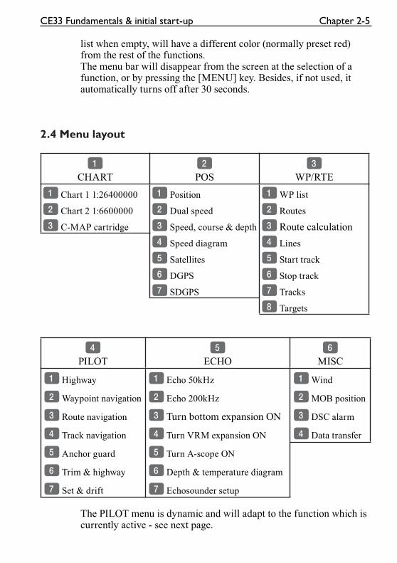
1
CHART2
POS3
WP/RTE
1 Chart 1 1:26400000 1 Position 1 WP list
2 Chart 2 1:6600000 2 Dual speed 2 Routes
3 C-MAP cartridge 3 Speed, course & depth 3 Route calculation
4 Speed diagram 4 Lines
5 Satellites 5 Start track
6 DGPS 6 Stop track
7 SDGPS 7 Tracks
8 Targets
4
PILOT5
ECHO6
MISC
1 Highway 1 Echo 50kHz 1 Wind
2 Waypoint navigation 2 Echo 200kHz 2 MOB position
3 Route navigation 3 Turn bottom expansion ON 3 DSC alarm
4 Track navigation 4 Turn VRM expansion ON 4 Data transfer
5 Anchor guard 5 Turn A-scope ON
6 Trim & highway 6 Depth & temperature diagram
7 Set & drift 7 Echosounder setup
The PILOT menu is dynamic and will adapt to the function which is currently active - see next page.
Chapter 2-6 CE33 Fundamentals & initial start-up
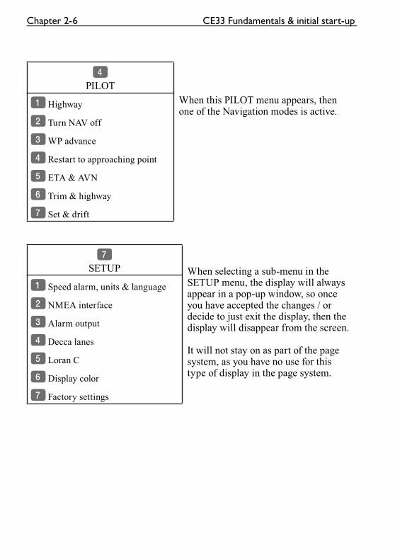
4
PILOT
When this PILOT menu appears, then one of the Navigation modes is active.
1 Highway
2 Turn NAV off
3 WP advance
4 Restart to approaching point
5 ETA & AVN
6 Trim & highway
7 Set & drift
7
SETUP When selecting a sub-menu in the SETUP menu, the display will always appear in a pop-up window, so once you have accepted the changes / or decide to just exit the display, then the display will disappear from the screen.
It will not stay on as part of the page system, as you have no use for this type of display in the page system.
1 Speed alarm, units & language
2 NMEA interface
3 Alarm output
4 Decca lanes
5 Loran C
6 Display color
7 Factory settings
CE33 Fundamentals & initial start-up Chapter 2-7
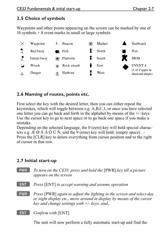
2.5 Choice of symbols
Waypoints and other points appearing on the screen can be marked by one of 18 symbols + 8 event marks in small or large symbols:
2.6 Naming of routes, points etc.
First select the key with the desired letter, then you can either repeat the keystrokes, which will toggle between e.g. A,B,C,1, or once you have selected one letter you can go back and forth in the alphabet by means of the +/- keys. Use the cursor key to go to next space or to go back one space if you make a mistake.Depending on the selected language, the 0 (zero) key will hold special charac-ters e.g. Æ Ø Å Ä Ö Ü Ñ, and the 9 (nine) key will hold: (empty space) . -Press the [CLR] key to delete everything from cursor position and to the right of cursor in that row.
2.7 Initial start-up
PWR To turn on the CE33, press and hold the [PWR] key till a picture appears on the screen
ENT Press [ENT] to accept warning and assume operation
PWR Press [PWR] again to adjust the lighting in the screen and select day or night display etc., move around in display by means of the cursor key and change settings with +/- keys, and...
ENT Confirm with [ENT]
The unit will now perform a fully automatic start-up and find the
Chapter 2-8 CE33 Fundamentals & initial start-up
correct position without further data entries. The start-up phase is completed when a position appears in the position display - see sec-tion 4.1.
The echosounder function has a demo program, which can be acti-vated in the Echosounder setup display, refer to section 7.8.
� When a transducer has been installed and selected, and the Echosounder function is set up and ready to perform, please make sure that the demo mode is switched OFF.
Select display language:
MENU Call up the menu bar, and...
7,1 press [7], [1] to call up the language display
Press up on the cursor to go to the bottom line in the display
+/- Select language
ENT Confirm entry
2.8 Turn power off
PWR Call up INFO window, and...
PWR Press and hold until screen turns black
The CE33 is now turned off. All the data and setups are saved and stored in the internal memory and, of course, will be available next time the unit is turned on.
CE33 Chart menu and INFO windows Chapter 3-1
3. Chart menu
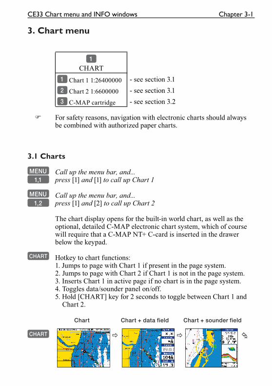
1
CHART
1 Chart 1 1:26400000 - see section 3.1
2 Chart 2 1:6600000 - see section 3.1
3 C-MAP cartridge - see section 3.2
� For safety reasons, navigation with electronic charts should always be combined with authorized paper charts.
3.1 Charts
MENU Call up the menu bar, and...1,1 press [1] and [1] to call up Chart 1
MENU Call up the menu bar, and...1,2 press [1] and [2] to call up Chart 2
The chart display opens for the built-in world chart, as well as the optional, detailed C-MAP electronic chart system, which of course will require that a C-MAP NT+ C-card is inserted in the drawer below the keypad.
CHART Hotkey to chart functions:1. Jumps to page with Chart 1 if present in the page system.2. Jumps to page with Chart 2 if Chart 1 is not in the page system.3. Inserts Chart 1 in active page if no chart is in the page system.4. Toggles data/sounder panel on/off.5. Hold [CHART] key for 2 seconds to toggle between Chart 1 and
Chart 2.
Chart Chart + data field Chart + sounder field
CHART � � �
Chapter 3-2 CE33 Chart menu and INFO windows
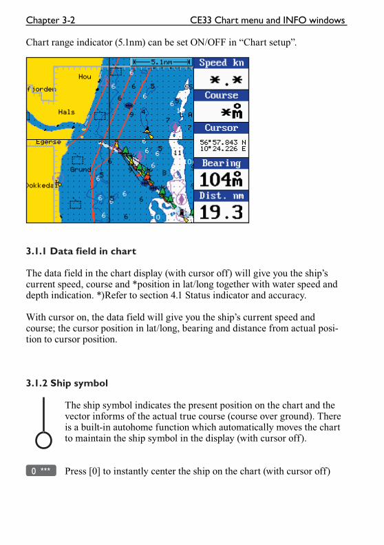
Chart range indicator (5.1nm) can be set ON/OFF in “Chart setup”.
3.1.1 Data field in chart
The data field in the chart display (with cursor off) will give you the ship’s current speed, course and *position in lat/long together with water speed and depth indication. *)Refer to section 4.1 Status indicator and accuracy.
With cursor on, the data field will give you the ship’s current speed and course; the cursor position in lat/long, bearing and distance from actual posi-tion to cursor position.
3.1.2 Ship symbol
The ship symbol indicates the present position on the chart and the vector informs of the actual true course (course over ground). There is a built-in autohome function which automatically moves the chart to maintain the ship symbol in the display (with cursor off).
0 *** Press [0] to instantly center the ship on the chart (with cursor off)
CE33 Chart menu and INFO windows Chapter 3-3
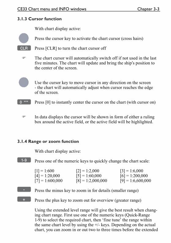
3.1.3 Cursor function
With chart display active:
Press the cursor key to activate the chart cursor (cross hairs)
CLR Press [CLR] to turn the chart cursor off
� The chart cursor will automatically switch off if not used in the last five minutes. The chart will update and bring the ship’s position to the center of the screen.
Use the cursor key to move cursor in any direction on the screen - the chart will automatically adjust when cursor reaches the edge of the screen.
0 *** Press [0] to instantly center the cursor on the chart (with cursor on)
� In data displays the cursor will be shown in form of either a ruling box around the active field, or the active field will be highlighted.
3.1.4 Range or zoom function
With chart display active:
1-9 Press one of the numeric keys to quickly change the chart scale:
[1] = 1:600 [2] = 1:2,000 [3] = 1:6,000[4] = 1:20,000 [5] = 1:60,000 [6] = 1:200,000[7] = 1:600,000 [8] = 1:2,000,000 [9] = 1:6,600,000
- Press the minus key to zoom in for details (smaller range)
+ Press the plus key to zoom out for overview (greater range)
Using the extended level range will give the best result when chang-ing chart range. First use one of the numeric keys (Quick-Range 1-9) to select the required chart, then ‘fine tune’ the range within the same chart level by using the +/- keys. Depending on the actual chart, you can zoom in or out two to three times before the extended

Chapter 3-4 CE33 Chart menu and INFO windows
level range is switched off and the chart changes to a new level of details.
� The extended level range can be toggled OFF/ON in chart setup (default = ON). See section 3.4 Chart setup.
Chart details may not be available in all scales in all areas. Non-covered areas will be marked as hatched or all blue/white with coordinate grid (when Grid is set to AUTO (default) in chart setup), depending on the actual scale - see section 3.4 Chart setup for more details in regard to what can be shown on the chart and what you may choose not to have shown.
The built-in world chart can be zoomed up/down in six steps, from a scale of approx. 1:33,000,000 to 1:2,000,000.
An over-zoom function enables you to zoom beyond the chart, which automatically is switched off and replaced by a lat/long coor-dinate grid. In this mode, the scale can go down to 1:600.
CE33 Chart menu and INFO windows Chapter 3-5
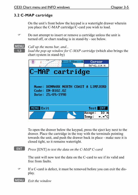
3.2 C-MAP cartridge
On the unit’s front below the keypad is a watertight drawer wherein you place the C-MAP cartridge/C-card you wish to load.
� Do not attempt to insert or remove a cartridge unless the unit is turned off, or chart reading is in stand-by - see below.
MENU Call up the menu bar, and...1,3 load the pop-up window for C-MAP cartridge (which also brings the
chart system in stand-by)
To open the drawer below the keypad, press the eject key next to the drawer. Place the cartridge in the tray with the terminals pointing towards the unit, and push the drawer back in place - make sure it is closed tight, so it remains watertight.
ENT Press [ENT] to test the data on the C-MAP C-card
The unit will now test the data on the C-card to see if its valid and free from faults.
� If a C-card is defect, it must be removed before you can exit the dis-play.
MENU Exit the window
Chapter 3-6 CE33 Chart menu and INFO windows
In addition to the larger boundaries of the world chart there will be separate boundary lines for the individual charts stored on the same cartridge. However, the boundary lines for the C-MAP chart areas can be turned off, so they will not be visible on the chart - refer to section 3.4 Chart setup.
Other chart areas can quickly be reached by means of the zoom keys:
+ Zoom out until desired area becomes visible
Move cursor to approximate area, and...
- Zoom in
The chart will automatically start to move when cursor reaches the edge of the screen. When cursor is switched off [CLR], the chart will return to ship’s position.
� See also section 3.4 Chart setup.
CE33 Chart menu and INFO windows Chapter 3-7
3.3 INFO windows
A number of pop-up INFO windows are available mainly from active chart display. Only a few of the functions in the INFO win-dows can be accessed from data displays and other displays. Refer to sections 3.3.x.
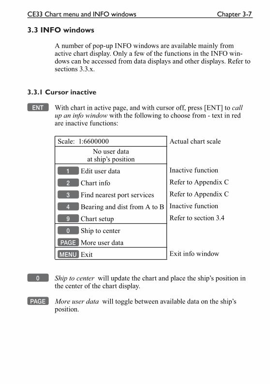
3.3.1 Cursor inactive
ENT With chart in active page, and with cursor off, press [ENT] to call up an info window with the following to choose from - text in red are inactive functions:
Scale: 1:6600000 Actual chart scale
No user dataat ship’s position
1 Edit user data Inactive function
2 Chart info Refer to Appendix C
3 Find nearest port services Refer to Appendix C
4 Bearing and dist from A to B Inactive function
9 Chart setup Refer to section 3.4
0 Ship to center
PAGE More user data
MENU Exit Exit info window
0 Ship to center will update the chart and place the ship’s position in the center of the chart display.
PAGE More user data will toggle between available data on the ship’s position.
Chapter 3-8 CE33 Chart menu and INFO windows
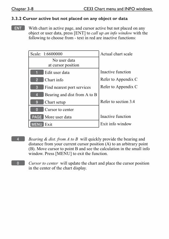
3.3.2 Cursor active but not placed on any object or data
ENT With chart in active page, and cursor active but not placed on any object or user data, press [ENT] to call up an info window with the following to choose from - text in red are inactive functions:
Scale: 1:6600000 Actual chart scale
No user dataat cursor position
1 Edit user data Inactive function
2 Chart info Refer to Appendix C
3 Find nearest port services Refer to Appendix C
4 Bearing and dist from A to B
9 Chart setup Refer to section 3.4
0 Cursor to center
PAGE More user data Inactive function
MENU Exit Exit info window
4 Bearing & dist. from A to B will quickly provide the bearing and distance from your current cursor position (A) to an arbitrary point (B). Move cursor to point B and see the calculation in the small info window. Press [MENU] to exit the function.
0 Cursor to center will update the chart and place the cursor position in the center of the chart display.
CE33 Chart menu and INFO windows Chapter 3-9
3.3.3 Cursor placed on waypoint
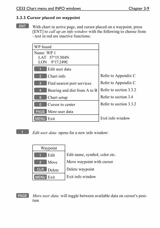
ENT With chart in active page, and cursor placed on a waypoint, press [ENT] to call up an info window with the following to choose from - text in red are inactive functions:
WP found
Name: WP 1 LAT 57°15.504N LON 9°17.249E
1 Edit user data
2 Chart info Refer to Appendix C
3 Find nearest port services Refer to Appendix C
4 Bearing and dist from A to B Refer to section 3.3.2
9 Chart setup Refer to section 3.4
0 Cursor to center Refer to section 3.3.2
PAGE More user data
MENU Exit Exit info window
1 Edit user data opens for a new info window:
Waypoint
1 Edit Edit name, symbol, color etc.
2 Move Move waypoint with cursor
CLR Delete Delete waypoint
MENU Exit Exit info window
PAGE More user data will toggle between available data on cursor’s posi-tion
Chapter 3-10 CE33 Chart menu and INFO windows
3.3.4 Cursor placed on route leg or line section
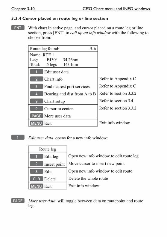
ENT With chart in active page, and cursor placed on a route leg or line section, press [ENT] to call up an info window with the following to choose from:
Route leg found: 5-6
Name: RTE 1Leg: B130° 34.26nmTotal: 5 legs 143.1nm
1 Edit user data
2 Chart info Refer to Appendix C
3 Find nearest port services Refer to Appendix C
4 Bearing and dist from A to B Refer to section 3.3.2
9 Chart setup Refer to section 3.4
0 Cursor to center Refer to section 3.3.2
PAGE More user data
MENU Exit Exit info window
1 Edit user data opens for a new info window:
Route leg
1 Edit leg Open new info window to edit route leg
2 Insert point Move cursor to insert new point
3 Edit Open new info window to edit route
CLR Delete Delete the whole route
MENU Exit Exit info window
PAGE More user data will toggle between data on routepoint and route leg.
CE33 Chart menu and INFO windows Chapter 3-11
3.3.5 Cursor placed on routepoint or linepoint
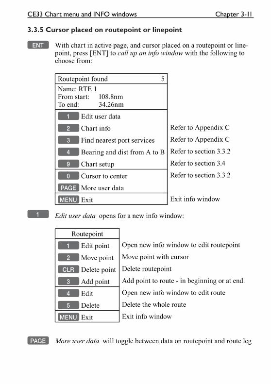
ENT With chart in active page, and cursor placed on a routepoint or line-point, press [ENT] to call up an info window with the following to choose from:
Routepoint found 5
Name: RTE 1From start: 108.8nmTo end: 34.26nm
1 Edit user data
2 Chart info Refer to Appendix C
3 Find nearest port services Refer to Appendix C
4 Bearing and dist from A to B Refer to section 3.3.2
9 Chart setup Refer to section 3.4
0 Cursor to center Refer to section 3.3.2
PAGE More user data
MENU Exit Exit info window
1 Edit user data opens for a new info window:
Routepoint
1 Edit point Open new info window to edit routepoint
2 Move point Move point with cursor
CLR Delete point Delete routepoint
3 Add point Add point to route - in beginning or at end.
4 Edit Open new info window to edit route
5 Delete Delete the whole route
MENU Exit Exit info window
PAGE More user data will toggle between data on routepoint and route leg
Chapter 3-12 CE33 Chart menu and INFO windows
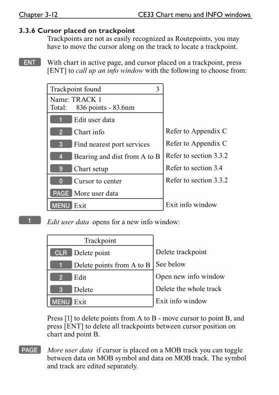
3.3.6 Cursor placed on trackpointTrackpoints are not as easily recognized as Routepoints, you may have to move the cursor along on the track to locate a trackpoint.
ENT With chart in active page, and cursor placed on a trackpoint, press [ENT] to call up an info window with the following to choose from:
Trackpoint found 3
Name: TRACK 1Total: 836 points - 83.6nm
1 Edit user data
2 Chart info Refer to Appendix C
3 Find nearest port services Refer to Appendix C
4 Bearing and dist from A to B Refer to section 3.3.2
9 Chart setup Refer to section 3.4
0 Cursor to center Refer to section 3.3.2
PAGE More user data
MENU Exit Exit info window
1 Edit user data opens for a new info window:
Trackpoint
CLR Delete point Delete trackpoint
1 Delete points from A to B See below
2 Edit Open new info window
3 Delete Delete the whole track
MENU Exit Exit info window
Press [1] to delete points from A to B - move cursor to point B, and press [ENT] to delete all trackpoints between cursor position on chart and point B.
PAGE More user data if cursor is placed on a MOB track you can toggle between data on MOB symbol and data on MOB track. The symbol and track are edited separately.
CE33 Chart menu and INFO windows Chapter 3-13
3.3.7 Cursor placed on target
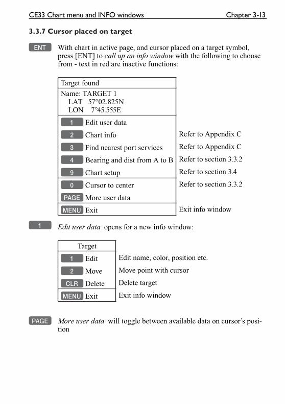
ENT With chart in active page, and cursor placed on a target symbol, press [ENT] to call up an info window with the following to choose from - text in red are inactive functions:
Target found
Name: TARGET 1 LAT 57°02.825N LON 7°45.555E
1 Edit user data
2 Chart info Refer to Appendix C
3 Find nearest port services Refer to Appendix C
4 Bearing and dist from A to B Refer to section 3.3.2
9 Chart setup Refer to section 3.4
0 Cursor to center Refer to section 3.3.2
PAGE More user data
MENU Exit Exit info window
1 Edit user data opens for a new info window:
Target
1 Edit Edit name, color, position etc.
2 Move Move point with cursor
CLR Delete Delete target
MENU Exit Exit info window
PAGE More user data will toggle between available data on cursor’s posi-
tion
Chapter 3-14 CE33 Chart menu and INFO windows
3.3.8 GOTO function
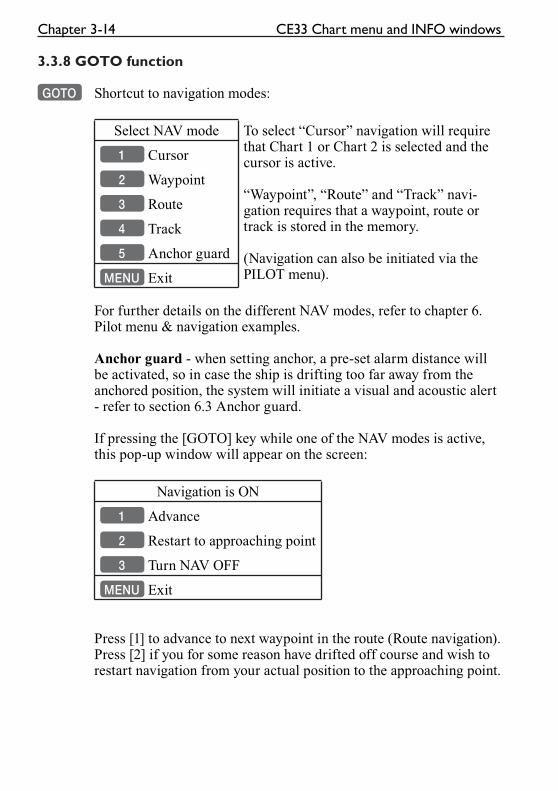
GOTO Shortcut to navigation modes:
Select NAV mode To select “Cursor” navigation will require that Chart 1 or Chart 2 is selected and the cursor is active.
“Waypoint”, “Route” and “Track” navi-gation requires that a waypoint, route or track is stored in the memory.
(Navigation can also be initiated via the PILOT menu).
1 Cursor
2 Waypoint
3 Route
4 Track
5 Anchor guard
MENU Exit
For further details on the different NAV modes, refer to chapter 6. Pilot menu & navigation examples.
Anchor guard - when setting anchor, a pre-set alarm distance will be activated, so in case the ship is drifting too far away from the anchored position, the system will initiate a visual and acoustic alert - refer to section 6.3 Anchor guard.
If pressing the [GOTO] key while one of the NAV modes is active, this pop-up window will appear on the screen:
Navigation is ON
1 Advance
2 Restart to approaching point
3 Turn NAV OFF
MENU Exit
Press [1] to advance to next waypoint in the route (Route navigation).Press [2] if you for some reason have drifted off course and wish to restart navigation from your actual position to the approaching point.
CE33 Chart menu and INFO windows Chapter 3-15
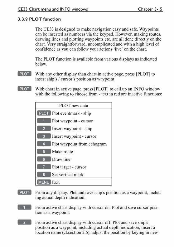
3.3.9 PLOT function
The CE33 is designed to make navigation easy and safe. Waypoints can be inserted as numbers via the keypad. However, making routes, drawing lines and plotting waypoints etc. are all done directly on the chart. Very straightforward, uncomplicated and with a high level of confidence as you can follow your actions ‘live’ on the chart.
The PLOT function is available from various displays as indicated below.
PLOT With any other display than chart in active page, press [PLOT] to insert ship’s / cursor’s position as waypoint
PLOT With chart in active page, press [PLOT] to call up an INFO window with the following to choose from - text in red are inactive functions:
PLOT new data
PLOT Plot eventmark - ship
1 Plot waypoint - cursor
2 Insert waypoint - ship
3 Insert waypoint - cursor
4 Plot waypoint from echogram
5 Make route
6 Draw line
7 Plot target - cursor
8 Set vertical mark
MENU Exit
PLOT From any display: Plot and save ship’s position as a waypoint, includ-ing actual depth indication.
1 From active chart display with cursor on: Plot and save cursor posi-tion as a waypoint.
2 From active chart display with cursor off: Plot and save ship’s position as a waypoint, including actual depth indication; insert a location name (cf.section 2.6), adjust the position by keying in new
Chapter 3-16 CE33 Chart menu and INFO windows
figures, change the symbol (cf.section 2.5).
3 From active chart display with cursor on: Plot and save cursor’s position as a waypoint; insert a location name (cf.section 2.6), adjust the position by keying in new figures, change the symbol (cf.section 2.5).
4 From active echo display: Plot and save waypoint, from echogram. Move cursor and press [ENT] to save spot as waypoint, including actual depth indication. Add a name, symbol, color etc.
5 From active chart display with cursor on: You can quickly make a route by means of the cursor and the [PLOT] key. The present cursor position will be the first position of the route you are about to make. Move cursor to next position, and press [PLOT]. Continue in this manner until the route is completed.
Existing waypoints can be used for making the route, simply by placing the cursor on the waypoints and plot the positions. In case you make a wrong plot, press [CLR] to erase the last plotted posi-tion. Save the route with [ENT] or exit the function with [MENU] to abandon the route.
� Do not use the exact position of buoys, markers etc. as waypoints and routepoints. The high accuracy of the system may result in a col-lision when sailing in the dark or navigating with an autopilot.
6 From active chart display with cursor on: To draw lines or to make a route is the same procedure, please refer to point 5.
7 From active chart display with cursor on: Plot target at cursor posi-tion with preset target name etc., or...
from active chart display with cursor off: Plot target at ship’s posi-tion with preset target name etc.
After plotting the target it will be saved in the memory, and you can edit the target later on, either via the menu (cf.section 5.7) or directly from the chart (cf.section 3.3.7).
8 From active echo display: Plot vertical marker (line) at the current ping in the echo display.
CE33 Chart menu and INFO windows Chapter 3-17
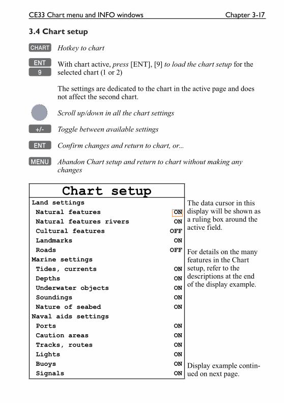
3.4 Chart setup
CHART Hotkey to chart
ENT With chart active, press [ENT], [9] to load the chart setup for the 9 selected chart (1 or 2)
The settings are dedicated to the chart in the active page and does not affect the second chart.
Scroll up/down in all the chart settings
+/- Toggle between available settings
ENT Confirm changes and return to chart, or...
MENU Abandon Chart setup and return to chart without making any changes
Chart setupLand settings
Natural features ON
Natural features rivers ON
Cultural features OFF
Landmarks ON
Roads OFF
Marine settings
Tides, currents ON
Depths ON
Underwater objects ON
Soundings ON
Nature of seabed ON
Naval aids settings
Ports ON
Caution areas ON
Tracks, routes ON
Lights ON
Buoys ON
Signals ON
The data cursor in this display will be shown as a ruling box around the active field.
For details on the many features in the Chart setup, refer to the descriptions at the end of the display example.
Display example contin-ued on next page.
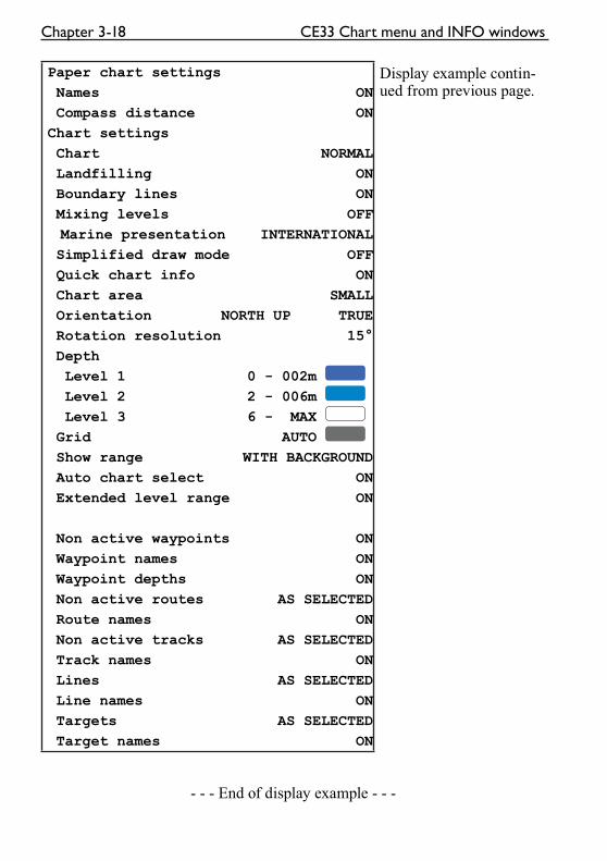
Chapter 3-18 CE33 Chart menu and INFO windows
Paper chart settings
Names ON
Compass distance ON
Chart settings
Chart NORMAL
Landfilling ON
Boundary lines ON
Mixing levels OFF
Marine presentation INTERNATIONAL
Simplified draw mode OFF
Quick chart info ON
Chart area SMALL
Orientation NORTH UP TRUE
Rotation resolution 15°
Depth
Level 1 0 - 002m
Level 2 2 - 006m
Level 3 6 - MAX
Grid AUTO
Show range WITH BACKGROUND
Auto chart select ON
Extended level range ON
Non active waypoints ON
Waypoint names ON
Waypoint depths ON
Non active routes AS SELECTED
Route names ON
Non active tracks AS SELECTED
Track names ON
Lines AS SELECTED
Line names ON
Targets AS SELECTED
Target names ON
Display example contin-ued from previous page.
- - - End of display example - - -
CE33 Chart menu and INFO windows Chapter 3-19
All C-MAP feature groups i.e. Land settings, Marine settings, Naval aids set-tings and Paper chart settings are described in Appendix C.
To obtain a ‘cleaner’ view of the chart details, you can turn some of the set-tings OFF if they do not contribute to the clarity of the chart area you wish to explore. All the listed objects that can be turned on and off speaks for themselves - they are either ‘on=shown on the chart’ or ‘off=not shown on the chart’.
All user data in the CE33 system are listed under ‘Chart settings’ in the dis-play example and are described below:
Chart can be set to NORMAL, COMPRESSED or CHART OFF:NORMAL - (default) will automatically select the chart level appropriate for the selected range/scale.COMPRESSED - will change the range (scale) / chart level ratio one step, which, depending on the actual chart, will select a more detailed level.CHART OFF - will only show all the user-made data such as waypoints, routes, lines and tracks etc.
Landfilling - default=ON. When set to Off there will be no special color to indicate where there is land i.e. land will be all blue.
Boundary lines (default=ON) will indicate available C-MAP chart areas.
Mixing levels (default =OFF) when set to ON you will no longer see any blank chart areas, as the C-MAP library will find the missing area in a differ-ent level to cover the blank area otherwise left on the screen. However, when using this feature, chart re-draw time will be increased a little.
Marine presentation can be set to INTERNATIONAL or AMERICAN:INTERNATIONAL - (default) will present NavAids in ‘real life’ shapes and colors for quick visual recognition (as per official INT1 standard paper chart presentation).AMERICAN - will present NavAids in simplified shapes and real colors (as generally found on NOAA paper charts).
Simplified draw mode (default=OFF) - when set to ON the NavAids will be shown in generic symbols for minimum visual clutter on-screen.
Quick chart info (default=ON) - placing the chart cursor on a C-MAP object will activate a small info window with details on the object. Info window will automatically close after 10 seconds or when cursor is moved away.
Chapter 3-20 CE33 Chart menu and INFO windows
Chart area can be set to SMALL, MEDIUM or LARGE:SMALL - (default) will open a small chart area big enough to just fill the size of the screen. When panning and scrolling, the chart will automatically be redrawn.MEDIUM - will open a medium-sized chart area for pan and scroll which goes beyond the size of the screen. The chart redraw time increases equally.LARGE - will open a large chart area for pan and scroll in a size which goes well beyond the size of the screen. The chart redraw time increases equally.
Orientation - can be set to NORTH UP, HEAD UP or NAV UP, and the mode can be RELATIVE or TRUE motion. NORTH UP - (default) the chart will always be presented as north up.HEAD UP - the chart will automatically turn, so your actual course (COG) is up. If chart cursor is active it will stop the chart from rotating, press [CLR] to turn cursor off. If a compass is connected, the reference will automatically change to heading (compass). NAV UP - the chart will automatically turn, so your bearing to destination is up. If chart cursor is active it will stop the chart from rotating, press [CLR] to turn cursor off.
TRUE motion - (default) the ‘ship’ will move across the chart.RELATIVE motion - (‘Chart area’ will default to MEDIUM). The ‘ship is locked to the center of the screen and the chart will move.
Rotation resolution - (default=15°) can be set to adjust the chart for each 5, 10, 15, 20 or 25° changes in present course or heading.
Depth: Level 1, 2 and 3 - are identified by different colors. The number of meters in the levels can be changed. The colors are preset in the Palette setup, section 9.6.
Grid - (default=AUTO) the LAT/LON grid can be set to AUTO, ON or OFF. The color of the grid is preset in the Palette setup, section 9.6.
Show range - can be set to WITH BACKGROUND, ON or OFF:WITH BACKGROUND - (default) will add a small line to the chart display indicating that the length of the line equals a certain number of nautical miles/km - the indication is highlighted with a background color.ON - same as above, but without background color.OFF - indication is not shown on chart.
Auto chart select - (default=ON) When sailing with ‘Auto chart select’ ON and cursor turned off, the scale will automatically change to the chart which is available. But when set to OFF, then the selected scale will remain, also when

CE33 Chart menu and INFO windows Chapter 3-21
sailing ‘out of the chart’.
Extended level range - (default=ON) will enable changing range 3-4 steps within the same chart level after having selected the range via a numeric key.
The remainder of the objects from ‘Non active waypoints’ can all be set to:ON= shown on chart; OFF= not shown on chart; AS SELECTED= the choices made for a particular route etc. via the menu e.g. MENU, 3, 2, ENT, ENT - Edit route, where ‘Course line’ can be set ON or OFF.

Chapter 3-22 CE33 Chart menu and INFO windows
CE33 Position menu Chapter 4-1
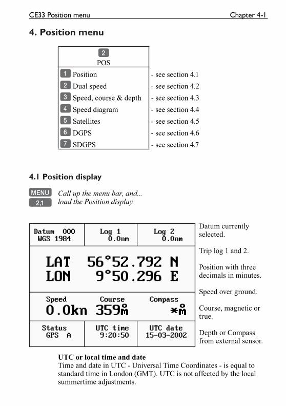
4. Position menu
2
POS
1 Position - see section 4.1
2 Dual speed - see section 4.2
3 Speed, course & depth - see section 4.3
4 Speed diagram - see section 4.4
5 Satellites - see section 4.5
6 DGPS - see section 4.6
7 SDGPS - see section 4.7
4.1 Position display
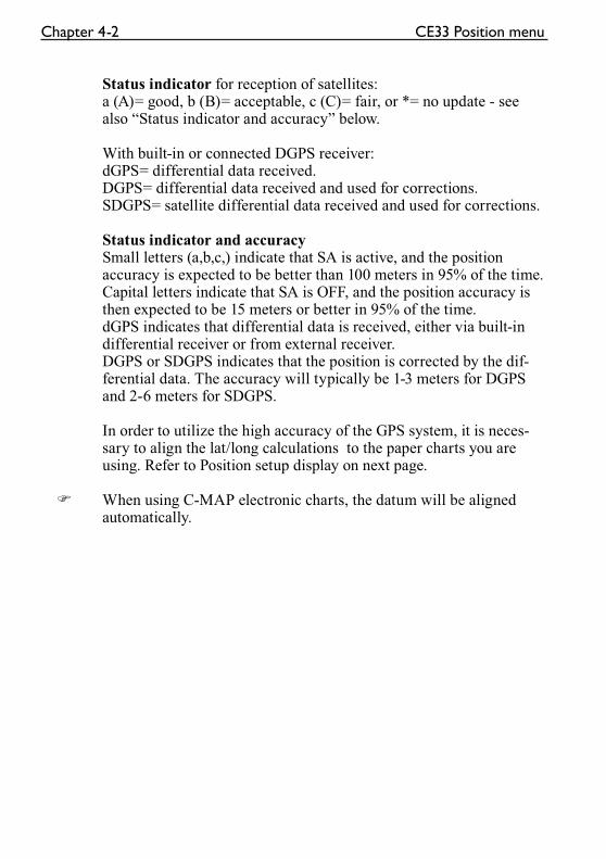
MENU Call up the menu bar, and...
2,1 load the Position display
Datum currently selected.
Trip log 1 and 2.
Position with three decimals in minutes.
Speed over ground.
Course, magnetic or true.
Depth or Compass from external sensor.
UTC or local time and dateTime and date in UTC - Universal Time Coordinates - is equal to standard time in London (GMT). UTC is not affected by the local summertime adjustments.
Chapter 4-2 CE33 Position menu
Status indicator for reception of satellites:a (A)= good, b (B)= acceptable, c (C)= fair, or *= no update - see also “Status indicator and accuracy” below.
With built-in or connected DGPS receiver:dGPS= differential data received.DGPS= differential data received and used for corrections.SDGPS= satellite differential data received and used for corrections.
Status indicator and accuracySmall letters (a,b,c,) indicate that SA is active, and the position accuracy is expected to be better than 100 meters in 95% of the time. Capital letters indicate that SA is OFF, and the position accuracy is then expected to be 15 meters or better in 95% of the time.dGPS indicates that differential data is received, either via built-in differential receiver or from external receiver.DGPS or SDGPS indicates that the position is corrected by the dif-ferential data. The accuracy will typically be 1-3 meters for DGPS and 2-6 meters for SDGPS.
In order to utilize the high accuracy of the GPS system, it is neces-sary to align the lat/long calculations to the paper charts you are using. Refer to Position setup display on next page.
� When using C-MAP electronic charts, the datum will be aligned automatically.
CE33 Position menu Chapter 4-3
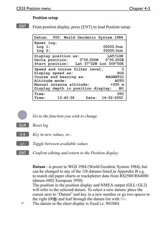
Position setup
ENT From position display, press [ENT] to load Position setup:
Datum: 000: World Geodetic System 1984
Reset log: Log 1: 00000.0nm Log 2: 00000.0nm
Display position as: LAT/LONDelta position: 0°00.000N 0°00.000EStart position: Lat 57°02N Lon 009°50E
Speed and course filter level: 3Display speed as: SOGCourse and bearing as: MAGNETICAltitude mode: AUTOManual antenna altitude: +005 mDisplay depth in position display: NO
Time: UTCTime: 13:43:56 Date: 14-02-2002
Go to the function you wish to change
CLR Reset log
0-9 Key in new values, or...
+/- Toggle between available values
ENT Confirm editing and return to the Position display
Datum - is preset to WGS 1984 (World Geodetic System 1984), but can be changed to any of the 118 datums listed in Appendix B e.g. to match old paper charts or trackplotter data from RS2500/RS4000 (datum #002 European 1950).The position in the position display and NMEA output (GLL+GL2) will refer to the selected datum. To select a new datum: place the cursor next to “Datum” and key in a new number or go two spaces to the right (000) and leaf through the datum list with +/-.
� The datum in the chart display is fixed i.e. WGS84.
Chapter 4-4 CE33 Position menu
Reset log - or insert alternative start figure by altering the value in the “Log 1” and/or “Log 2” line. Press [CLR] to reset the figure, and press the numeric keys 0-9 to alter the figure.
Display position as - the position can be shown in latitude/longitude, Loran C or decca coordinates (after selecting chain from the Setup menu). Toggle with +/-.
Delta position - some paper charts do not indicate a datum, but instead they have a notation to an offset or delta position to WGS84.Use numeric keys to key in the position correction.
Start position - can be inserted if the exact start position is known.
Speed and course filter level - there is a filter of 10 steps available (0= fast response, 9= stable readout).
Display speed as - SOG Speed Over Ground or STW Speed Through Water. Toggle with +/-.
� To receive STW information from external instrument (via NMEA port) will require that NMEA sentence VHW or “Log speed sensor” are set to ON. Refer to section 9.1 and 9.2.
Course and bearing as - readings of course and bearing can be made in either MAGNETIC or TRUE. Toggle with +/-.
Altitude mode - is preset to automatic, but can be changed to manual. Toggle with +/-.
Manual antenna altitude - is preset to 5 meters. Insert actual antenna height if manual altitude mode is selected. This value will not be shown anywhere else, but will be used for computations.
Display depth in position display - if set to YES, then the depth will be shown.When set to NO, then “Compass” from connected sensor will be shown instead.
Time - can be set to UTC or local. Toggle with +/-Correct actual time and date by means of the numeric keys.
CE33 Position menu Chapter 4-5
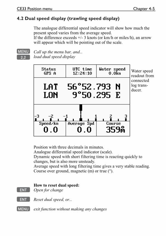
4.2 Dual speed display (trawling speed display)
The analogue differential speed indicator will show how much the present speed varies from the average speed.If the difference exceeds +/- 3 knots (or km/h or miles/h), an arrow will appear which will be pointing out of the scale.
MENU Call up the menu bar, and...
2,2 load dual speed display
Water speed readout from connected log trans-ducer.
Position with three decimals in minutes.Analogue differential speed indicator (scale).Dynamic speed with short filtering time is reacting quickly to changes, but is also more unsteady.Average speed with long filtering time gives a very stable reading.Course over ground, magnetic (m) or true (°).
How to reset dual speed:ENT Open for change
ENT Reset dual speed, or...
MENU exit function without making any changes
Chapter 4-6 CE33 Position menu
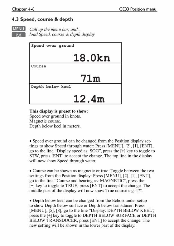
4.3 Speed, course & depth
MENU Call up the menu bar, and...
2,3 load Speed, course & depth display
Speed over ground
18.0knCourse
71mDepth below keel
12.4mThis display is preset to show:Speed over ground in knots.Magnetic course.Depth below keel in meters.
• Speed over ground can be changed from the Position display set-tings to show Speed through water: Press [MENU], [2], [1], [ENT], go to the line “Display speed as: SOG”, press the [+] key to toggle to STW, press [ENT] to accept the change. The top line in the display will now show Speed through water.
• Course can be shown as magnetic or true. Toggle between the two settings from the Position display: Press [MENU], [2], [1], [ENT], go to the line “Course and bearing as: MAGNETIC”, press the [+] key to toggle to TRUE, press [ENT] to accept the change. The middle part of the display will now show True course e.g. 17°.
• Depth below keel can be changed from the Echosounder setup to show Depth below surface or Depth below transducer. Press [MENU], [5], [8], go to the line “Display: DEPTH BELOW KEEL”, press the [+] key to toggle to DEPTH BELOW SURFACE or DEPTH BELOW TRANSDUCER, press [ENT] to accept the change. The new setting will be shown in the lower part of the display.
CE33 Position menu Chapter 4-7
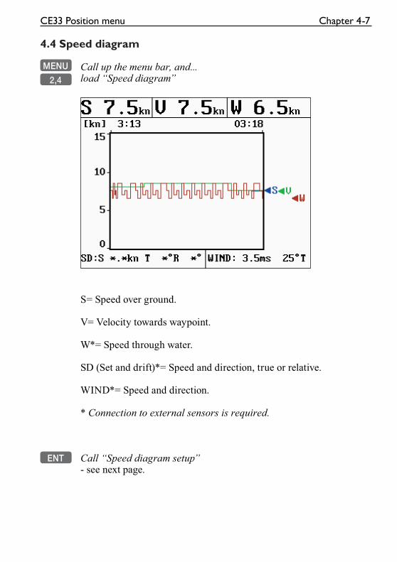
4.4 Speed diagram
MENU Call up the menu bar, and...
2,4 load “Speed diagram”
S= Speed over ground.
V= Velocity towards waypoint.
W*= Speed through water.
SD (Set and drift)*= Speed and direction, true or relative.
WIND*= Speed and direction.
* Connection to external sensors is required.
ENT Call “Speed diagram setup”- see next page.
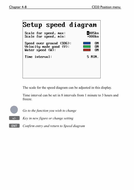
Chapter 4-8 CE33 Position menu
The scale for the speed diagram can be adjusted in this display.
Time interval can be set in 8 intervals from 1 minute to 3 hours and freeze.
Go to the function you wish to change
+/- Key in new figure or change setting
ENT Confirm entry and return to Speed diagram
CE33 Position menu Chapter 4-9
4.5 Satellite status
MENU Call up the menu bar, and...
2,5 load satellite status display
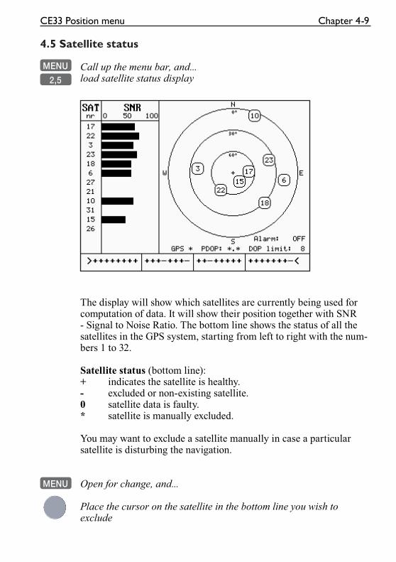
The display will show which satellites are currently being used for computation of data. It will show their position together with SNR - Signal to Noise Ratio. The bottom line shows the status of all the satellites in the GPS system, starting from left to right with the num-bers 1 to 32.
Satellite status (bottom line):+ indicates the satellite is healthy.- excluded or non-existing satellite.0 satellite data is faulty.* satellite is manually excluded.
You may want to exclude a satellite manually in case a particular satellite is disturbing the navigation.
MENU Open for change, and...
Place the cursor on the satellite in the bottom line you wish to exclude
Chapter 4-10 CE33 Position menu
- The minus key will exclude the satellite, and...
+ the plus key will reinstate it
ENT Confirm entry
HDOP, PDOP and DOP limits:
MENU Call up the menu bar, and...
2,5 load satellite status display
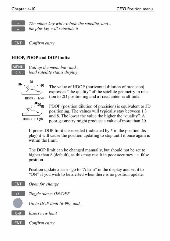
The value of HDOP (horizontal dilution of precision) expresses “the quality” of the satellite geometry in rela-tion to 2D positioning and a fixed antenna altitude.
PDOP (position dilution of precision) is equivalent to 3D positioning. The values will typically stay between 1.3 and 8. The lower the value the higher the “quality”. A poor geometry might produce a value of more than 20.
If preset DOP limit is exceeded (indicated by * in the position dis-play) it will cause the position updating to stop until it once again is within the limit.
The DOP limit can be changed manually, but should not be set to higher than 8 (default), as this may result in poor accuracy i.e. false position.
Position update alarm - go to “Alarm” in the display and set it to “ON” if you wish to be alerted when there is no position update.
ENT Open for change
+/- Toggle alarm ON/OFF
Go to DOP limit (6-99), and...
0-9 Insert new limit
ENT Confirm entry
CE33 Position menu Chapter 4-11
4.6 DGPS information
The DGPS - differential position corrections - can be provided from a built-in module, which is preset to full automatic operation, or from connected DGPS receiver - see “Status indicator” in position display.
� List of beacon stations is available in addendum, part no. 183.0122.501.
MENU Call up the menu bar, and...
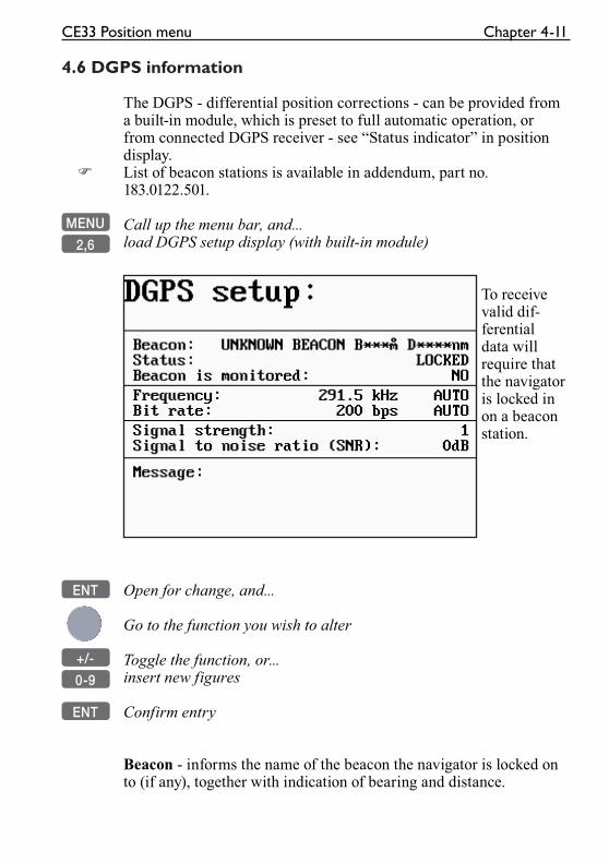
2,6 load DGPS setup display (with built-in module)
To receive valid dif-ferential data will require that the navigator is locked in on a beacon station.
ENT Open for change, and...
Go to the function you wish to alter
+/- Toggle the function, or...
0-9 insert new figures
ENT Confirm entry
Beacon - informs the name of the beacon the navigator is locked on to (if any), together with indication of bearing and distance.
Chapter 4-12 CE33 Position menu
Status - can either be:LOCKED = locked on a beacon and receiving differential data.NOT LOCKED = not locked on a becon and receiving no differen-tial data.NOT INSTALLED = there is no built-in DGPS module in unit.NOT IN USE = external DGPS receiver applied.
Beacon is monitored - YES or NO.If YES it should be safe to rely on the received differential data, because the beacon station’s performance is under observation. If NO, then you have to use the received differential data with cau-tion, as there is no guarantee it is not faulty.
Frequency - the frequency of the beacon station can be set manually if known. However, when left in AUTO the navigator will always search for the nearest station with a good signal strength.
Bit rate - indicates bits per second, and can be set manually to 25, 50, 100 or 200 bps.
Signal strength - a good signal strength is 20 and up.
Signal to noise ratio (SNR) - should be 8dB and up.
Message - type 16 message will be displayed when received from the DGPS system. The contents of this message could be something to do with the performance of the system. Temporarily out of service etc.
CE33 Position menu Chapter 4-13
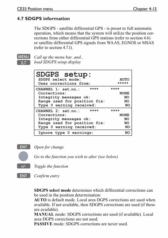
4.7 SDGPS information
The SDGPS - satellite differential GPS - is preset to full automatic operation, which means that the system will utilize the position cor-rections from either differential GPS stations (refer to section 4.6) or satellite differential GPS signals from WAAS, EGNOS or MSAS (refer to section 4.7.1).
MENU Call up the menu bar, and...
2,7 load SDGPS setup display
SDGPS setup: SDGPS select mode: AUTO Uses corrections from: *****
CHANNEL 1: sat.no.: **** **** Corrections: NONE Integrity messages ok: NO Range used for position fix: NO Type 0 warning received: NO
CHANNEL 2: sat.no.: **** **** Corrections: NONE Integrity messages ok: NO Range used for position fix: NO Type 0 warning received: NO
Ignore type 0 warnings: NO
ENT Open for change
Go to the function you wish to alter (see below)
+/- Toggle the function
ENT Confirm entry
SDGPS select mode determines which differential corrections can be used in the position determination:AUTO is default mode. Local area DGPS corrections are used when available. If not available, then SDGPS corrections are used (if these are available).MANUAL mode: SDGPS corrections are used (if available). Local area DGPS corrections are not used.PASSIVE mode: SDGPS corrections are never used.
Chapter 4-14 CE33 Position menu
Uses corrections from - indicates which differential corrections (DGPS or SDGPS) are currently used for position determination.
CHANNEL 1: sat.no. - indicates which satellite number and name is currently tracked/searched by channel 1, and what is the tracking state.
Corrections - indicates if corrections are being received on this channel. If YES: is the quality of the reception sufficiently high for the corrections to be usable.NONE: no corrections are received.RECEIVED: corrections are received, but of insufficient quality.USABLE: corrections are received and of sufficient quality.USED: corrections received on this channel are used in the position determination.
Integrity messages ok - the SDGPS system will transmit messages concerning the integrity of the GPS satellites. This line will indicate whether such messages are received and reliable.
Range used for position fix - if the receiver is tracking a particular SDGPS satellite, it “knows” the distance to that satellite. This line will indicate whether the distance is used in the position determina-tion.
Type 0 warning received - if an SDGPS satellite is not operat-ing according to specifications it will transmit a so-called “Type 0 warning”. In this situation, the receiver will not use any information that it might receive from that satellite. Until the SDGPS system is declared operational, the SDGPS satellites will always transmit Type 0 warnings.
� It is possible (but not recommendable) to override the Type 0 warn-ings - refer to last line in SDGPS setup: “Ignore type 0 warnings:NO” should be changed to “YES”.
CE33 Position menu Chapter 4-15
4.7.1 Satellites in SDGPS system
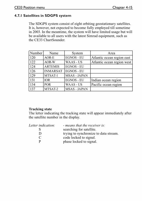
The SDGPS system consist of eight orbiting geostationary satellites. It is, however, not expected to become fully employed till sometime in 2003. In the meantime, the system will have limited usage but will be available to all users with the latest Simrad equipment, such as the CE33 ChartSounder.
Number Name System Area
120 AOR-E EGNOS - EU Atlantic ocean region east
122 AOR-W WAAS - US Atlantic ocean region west
124 ARTEMIS EGNOS - EU
126 INMARSAT EGNOS - EU
129 MTSAT-1 MSAS - JAPAN
131 IOR EGNOS - EU Indian ocean region
134 POR WAAS - US Pacific ocean region
137 MTSAT-2 MSAS - JAPAN
Tracking stateThe letter indicating the tracking state will appear immediately after the satellite number in the display.
Letter indication: - means that the receiver is: S searching for satellite. D trying to synchronize to data stream. C code locked to signal. P phase locked to signal.

Chapter 4-16 CE33 Position menu
CE33 Waypoint / route menu Chapter 5-1
5. Waypoint / route menu
3
WP/RTE
1 WP list - see section 5.1
2 Routes - see section 5.2
3 Route calculation - see section 5.3
4 Lines - see section 5.4
5 Start track - see section 5.5
6 Stop track - see section 5.5
7 Tracks - see section 5.6
8 Targets - see section 5.7
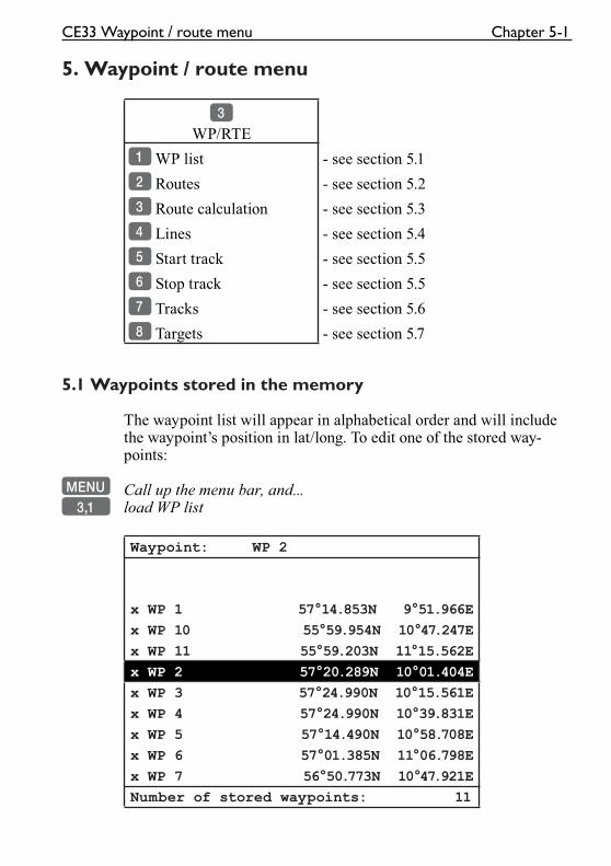
5.1 Waypoints stored in the memory
The waypoint list will appear in alphabetical order and will include the waypoint’s position in lat/long. To edit one of the stored way-points:
MENU Call up the menu bar, and...3,1 load WP list
Waypoint: WP 2
x WP 1 57°14.853N 9°51.966E
x WP 10 55°59.954N 10°47.247E
x WP 11 55°59.203N 11°15.562E
x WP 2 57°20.289N 10°01.404E
x WP 3 57°24.990N 10°15.561E
x WP 4 57°24.990N 10°39.831E
x WP 5 57°14.490N 10°58.708E
x WP 6 57°01.385N 11°06.798E
x WP 7 56°50.773N 10°47.921E
Number of stored waypoints: 11
Chapter 5-2 CE33 Waypoint / route menu
A-Z Insert name of waypoint you wish to edit, or...
+/- Leaf through waypoints with +/- keys or up/down cursor
ENT Open for editing
Place the cursor on the function you wish to change
0-9 Key in new figures, or...+/- toggle between available values
PLOT Move the position to ship’s position
ENT Confirm entry and return to WP list
� Plot new waypoints with the [PLOT] key - refer to section 3.3.9.
5.1.1 Delete waypoints via menu
MENU Call up the menu bar, and...3,1 load WP list
+/- Select waypoint you wish to delete
ENT Open for editing
GOTO Delete waypoint
CLR Confirm that you want to delete the selected waypoint, if not sure: press [MENU] to exit the display without having made any changes.
� Edit waypoints directly on the chart via info windows, refer to section 3.3.3.
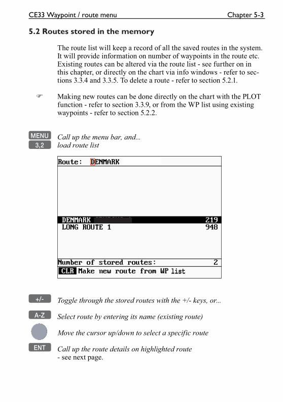
listlist
CE33 Waypoint / route menu Chapter 5-3
5.2 Routes stored in the memory
The route list will keep a record of all the saved routes in the system. It will provide information on number of waypoints in the route etc.Existing routes can be altered via the route list - see further on in this chapter, or directly on the chart via info windows - refer to sec-tions 3.3.4 and 3.3.5. To delete a route - refer to section 5.2.1.
� Making new routes can be done directly on the chart with the PLOT function - refer to section 3.3.9, or from the WP list using existing waypoints - refer to section 5.2.2.
MENU Call up the menu bar, and...3,2 load route list
+/- Toggle through the stored routes with the +/- keys, or...
A-Z Select route by entering its name (existing route)
Move the cursor up/down to select a specific route
ENT Call up the route details on highlighted route- see next page.
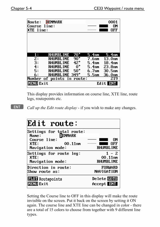
RoutepointsRoutepoints
Chapter 5-4 CE33 Waypoint / route menu
This display provides information on course line, XTE line, route legs, routepoints etc.
ENT Call up the Edit route display - if you wish to make any changes.
Setting the Course line to OFF in this display will make the route invisible on the screen. Put it back on the screen by setting it ON again. The course line and XTE line can be changed in color - there are a total of 15 colors to choose from together with 9 different line types.
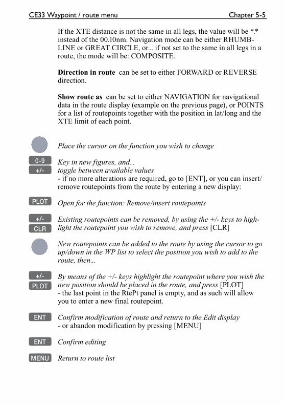
CE33 Waypoint / route menu Chapter 5-5
If the XTE distance is not the same in all legs, the value will be *.* instead of the 00.10nm. Navigation mode can be either RHUMB-LINE or GREAT CIRCLE, or... if not set to the same in all legs in a route, the mode will be: COMPOSITE.
Direction in route can be set to either FORWARD or REVERSE direction.
Show route as can be set to either NAVIGATION for navigational data in the route display (example on the previous page), or POINTS for a list of routepoints together with the position in lat/long and the XTE limit of each point.
Place the cursor on the function you wish to change
0-9 Key in new figures, and...+/- toggle between available values
- if no more alterations are required, go to [ENT], or you can insert/remove routepoints from the route by entering a new display:
PLOT Open for the function: Remove/insert routepoints
+/- Existing routepoints can be removed, by using the +/- keys to high-
CLR light the routepoint you wish to remove, and press [CLR]
New routepoints can be added to the route by using the cursor to go up/down in the WP list to select the position you wish to add to the route, then...
+/- By means of the +/- keys highlight the routepoint where you wish the
PLOT new position should be placed in the route, and press [PLOT]- the last point in the RtePt panel is empty, and as such will allow you to enter a new final routepoint.
ENT Confirm modification of route and return to the Edit display
- or abandon modification by pressing [MENU]
ENT Confirm editing
MENU Return to route list
Chapter 5-6 CE33 Waypoint / route menu
5.2.1 Delete route via menu
MENU Call up the menu bar, and...3,2 load route list
+/- Select the route you wish to delete
ENT Call up the route details on highlighted route
ENT Open for editing
GOTO Delete route
CLR Confirm that you want to delete the selected route, if not sure: press [MENU] to exit the display without having made any changes.
� Edit routes directly on the chart via info windows, refer to section 3.3.4 and 3.3.5.
5.2.2 Make new route from WP list
When you have a number of waypoints stored in the WP list which would be convenient to link together as a route it is easily done via the route list.
MENU Call up the menu bar, and...3,2 load route list
CLR Make new route from WP list
Use the cursor to go up/down in the WP list to select the position you wish to add to the route, then...
+/- By means of the +/- keys you can control where the highlighted posi-
PLOT tion is placed in the route, press [PLOT]- the last point in the RtePt panel is empty, and as such will allow you to enter a new final routepoint. Once a WP position is trans-ferred to the routepoint section, there is no longer any connection between the position and the waypoint in the WP list.
Select the next position and press [PLOT]. Continue in this manner until the route is completed. In case you make a wrong plot, you can delete the routepoint by highlighting the RtePt number by means of
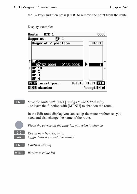
CE33 Waypoint / route menu Chapter 5-7
the +/- keys and then press [CLR] to remove the point from the route.
Display example:
ENT Save the route with [ENT] and go to the Edit display- or leave the function with [MENU] to abandon the route.
In the Edit route display you can set up the route preferences you need and also change the name of the route.
Place the cursor on the function you wish to change
0-9 Key in new figures, and...+/- toggle between available values
ENT Confirm editing
MENU Return to route list
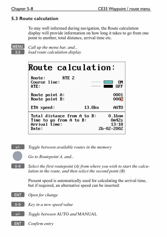
Chapter 5-8 CE33 Waypoint / route menu
5.3 Route calculation
To stay well informed during navigation, the Route calculation display will provide information on how long it takes to go from one point to another, total distance, arrival time etc.
MENU Call up the menu bar, and...3,3 load route calculation display
+/- Toggle between available routes in the memory
Go to Routepoint A, and...
0-9 Select the first routepoint (A) from where you wish to start the calcu-lation in the route, and then select the second point (B)
Present speed is automatically used for calculating the arrival time, but if required, an alternative speed can be inserted:
ENT Open for change
0-9 Key in a new speed value
+/- Toggle between AUTO and MANUAL
ENT Confirm entry
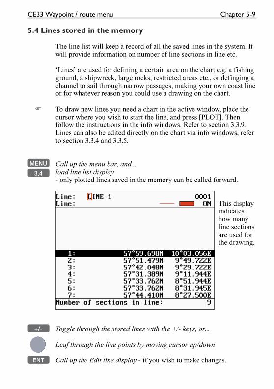
CE33 Waypoint / route menu Chapter 5-9
5.4 Lines stored in the memory
The line list will keep a record of all the saved lines in the system. It will provide information on number of line sections in line etc.
‘Lines’ are used for defining a certain area on the chart e.g. a fishing ground, a shipwreck, large rocks, restricted areas etc., or definging a channel to sail through narrow passages, making your own coast line or for whatever reason you could use a drawing on the chart.
� To draw new lines you need a chart in the active window, place the cursor where you wish to start the line, and press [PLOT]. Then follow the instructions in the info windows. Refer to section 3.3.9. Lines can also be edited directly on the chart via info windows, refer to section 3.3.4 and 3.3.5.
MENU Call up the menu bar, and...
3,4 load line list display- only plotted lines saved in the memory can be called forward.
This display indicates how many line sections are used for the drawing.
+/- Toggle through the stored lines with the +/- keys, or...
Leaf through the line points by moving cursor up/down
ENT Call up the Edit line display - if you wish to make changes.
Chapter 5-10 CE33 Waypoint / route menu
Turning “Line” OFF will make the line drawing invisible on the screen. Put it back on the screen by turning it ON again.
Place the cursor on the function you wish to change i.e. name, line type or color
+/- Toggle between available values
ENT Confirm entry
5.4.1 Delete lines via menu
MENU Call up the menu bar, and...3,4 load line list
+/- Select the line you wish to delete
ENT Open for editing
GOTO Delete line
CLR Confirm that you want to delete the selected line, if not sure: press [MENU] to exit the display without having made any changes.
� Edit lines directly on the chart via info windows, refer to section 3.3.4 and 3.3.5.
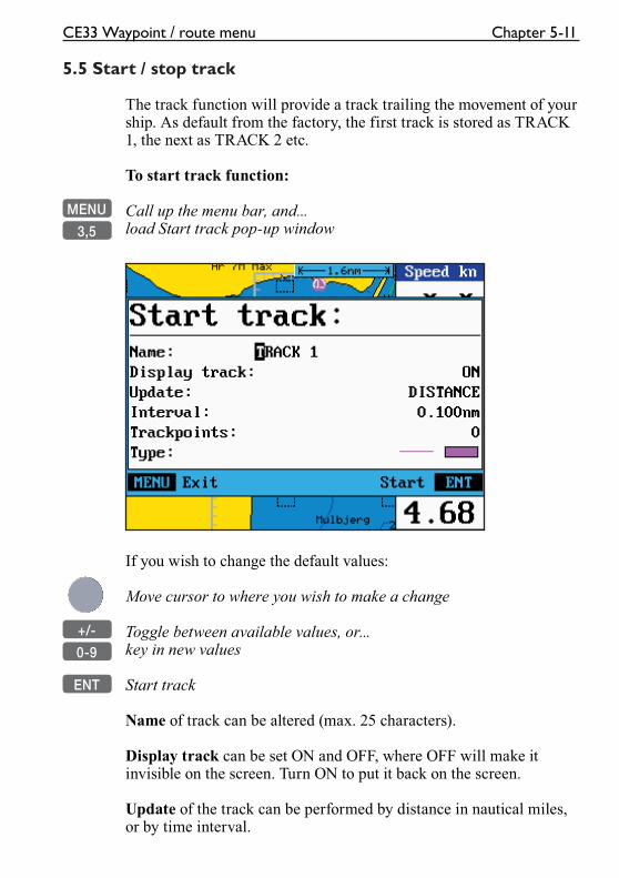
CE33 Waypoint / route menu Chapter 5-11
5.5 Start / stop track
The track function will provide a track trailing the movement of your ship. As default from the factory, the first track is stored as TRACK 1, the next as TRACK 2 etc.
To start track function:
MENU Call up the menu bar, and...
3,5 load Start track pop-up window
If you wish to change the default values:
Move cursor to where you wish to make a change
+/- Toggle between available values, or...
0-9 key in new values
ENT Start track
Name of track can be altered (max. 25 characters).
Display track can be set ON and OFF, where OFF will make it invisible on the screen. Turn ON to put it back on the screen.
Update of the track can be performed by distance in nautical miles, or by time interval.
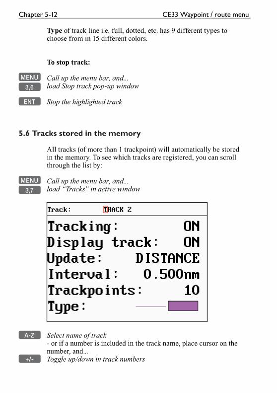
Chapter 5-12 CE33 Waypoint / route menu
Type of track line i.e. full, dotted, etc. has 9 different types to choose from in 15 different colors.
To stop track:
MENU Call up the menu bar, and...
3,6 load Stop track pop-up window
ENT Stop the highlighted track
5.6 Tracks stored in the memory
All tracks (of more than 1 trackpoint) will automatically be stored in the memory. To see which tracks are registered, you can scroll through the list by:
MENU Call up the menu bar, and...
3,7 load “Tracks” in active window
A-Z Select name of track- or if a number is included in the track name, place cursor on the number, and...
+/- Toggle up/down in track numbers
CE33 Waypoint / route menu Chapter 5-13
ENT Open for change
“Display track” can be set ON/OFF, where OFF will make it invis-ible on the screen. Turn ON to put it back on the screen.
+/- Toggle between available values
ENT Confirm changes
5.6.1 Delete tracks via menu
MENU Call up the menu bar, and...3,7 load track display
+/- Select the track you wish to delete
ENT Open for editing
GOTO Delete track
CLR Confirm that you want to delete the selected track, if not sure: press [MENU] to exit the display without having made any changes.
� Edit tracks directly on the chart via info windows, refer to section 3.3.6.
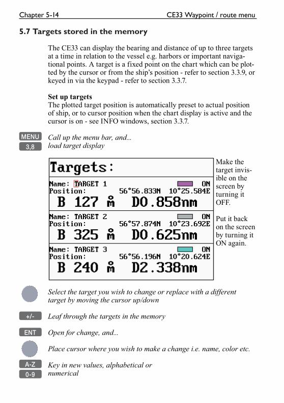
Chapter 5-14 CE33 Waypoint / route menu
5.7 Targets stored in the memory
The CE33 can display the bearing and distance of up to three targets at a time in relation to the vessel e.g. harbors or important naviga-tional points. A target is a fixed point on the chart which can be plot-ted by the cursor or from the ship’s position - refer to section 3.3.9, or keyed in via the keypad - refer to section 3.3.7.
Set up targetsThe plotted target position is automatically preset to actual position of ship, or to cursor position when the chart display is active and the cursor is on - see INFO windows, section 3.3.7.
MENU Call up the menu bar, and...
3,8 load target display
Make the target invis-ible on the screen by turning it OFF.
Put it back on the screen by turning it ON again.
Select the target you wish to change or replace with a different target by moving the cursor up/down
+/- Leaf through the targets in the memory
ENT Open for change, and...
Place cursor where you wish to make a change i.e. name, color etc.
A-Z Key in new values, alphabetical or
0-9 numerical
CE33 Waypoint / route menu Chapter 5-15
+/- Toggle between available values
ENT Confirm entry
5.7.1 Delete target via menu
MENU Call up the menu bar, and...3,8 load target display
+/- Select the target you wish to delete
ENT Open for editing
GOTO Delete target
CLR Confirm that you want to delete the selected target, if not sure: press [MENU] to exit the display without having made any changes.
� Edit targets directly on the chart via info windows, refer to section 3.3.7.

Chapter 5-16 CE33 Waypoint / route menu
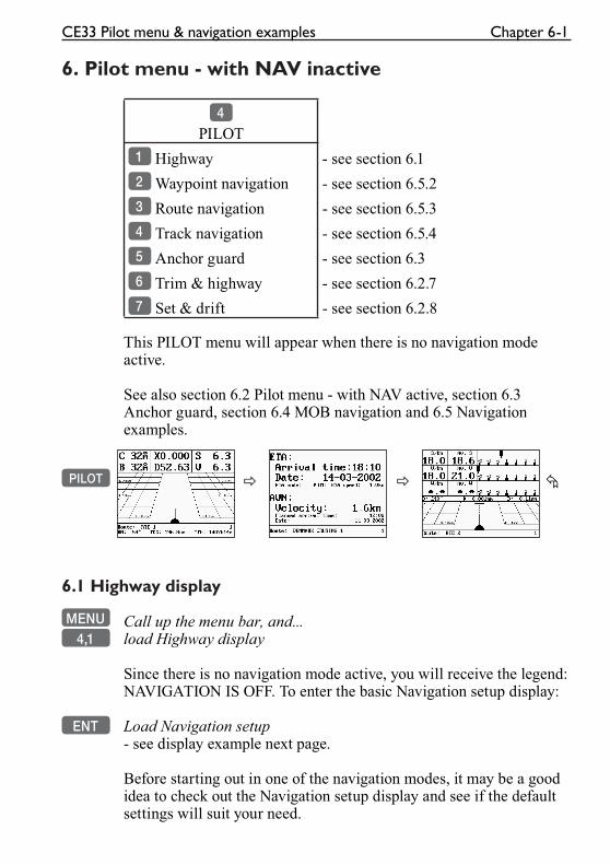
CE33 Pilot menu & navigation examples Chapter 6-1
6. Pilot menu - with NAV inactive
4
PILOT
1 Highway - see section 6.1
2 Waypoint navigation - see section 6.5.2
3 Route navigation - see section 6.5.3
4 Track navigation - see section 6.5.4
5 Anchor guard - see section 6.3
6 Trim & highway - see section 6.2.7
7 Set & drift - see section 6.2.8
This PILOT menu will appear when there is no navigation mode active.
See also section 6.2 Pilot menu - with NAV active, section 6.3 Anchor guard, section 6.4 MOB navigation and 6.5 Navigation examples.
PILOT � � �
6.1 Highway display
MENU Call up the menu bar, and...4,1 load Highway display
Since there is no navigation mode active, you will receive the legend: NAVIGATION IS OFF. To enter the basic Navigation setup display:
ENT Load Navigation setup- see display example next page.
Before starting out in one of the navigation modes, it may be a good idea to check out the Navigation setup display and see if the default settings will suit your need.
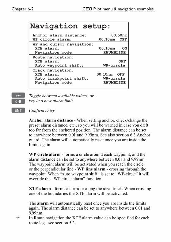
Chapter 6-2 CE33 Pilot menu & navigation examples
Navigation setup: Anchor alarm distance: 00.50nm WP circle alarm: 00.10nm OFF WP and cursor navigation: XTE alarm: 00.10nm ON Navigation mode: RHUMBLINE Route navigation: XTE alarm: OFF Auto waypoint shift: WP-circle Track navigation: XTE alarm: 00.10nm OFF Auto trackpoint shift: WP-circle Navigation mode: RHUMBLINE
+/- Toggle between available values, or...
0-9 key in a new alarm limit
ENT Confirm entry
Anchor alarm distance - When setting anchor, check/change the preset alarm distance, etc., so you will be warned in case you drift too far from the anchored position. The alarm distance can be set to anywhere between 0.01 and 9.99nm. See also section 6.3 Anchor guard. The alarm will automatically reset once you are inside the limits again.
WP circle alarm - forms a circle around each waypoint, and the alarm distance can be set to anywhere between 0.01 and 9.99nm.The waypoint alarm will be activated when you reach the circle or the perpendicular line - WP line alarm - crossing through the waypoint. When “Auto waypoint shift” is set to “WP-circle” it will override the “WP circle alarm” function.
XTE alarm - forms a corridor along the ideal track. When crossing one of the boundaries the XTE alarm will be activated.
The alarm will automatically reset once you are inside the limits again. The alarm distance can be set to anywhere between 0.01 and 9.99nm.
� In Route navigation the XTE alarm value can be specified for each route leg - see section 5.2.
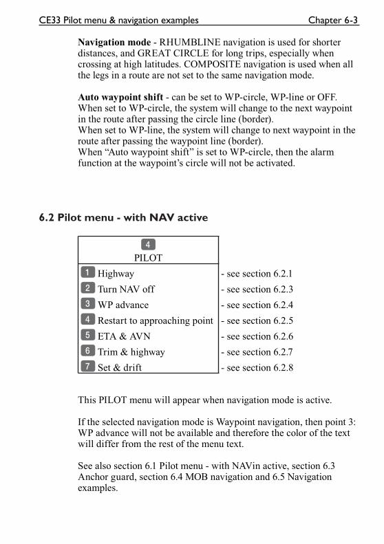
CE33 Pilot menu & navigation examples Chapter 6-3
Navigation mode - RHUMBLINE navigation is used for shorter distances, and GREAT CIRCLE for long trips, especially when crossing at high latitudes. COMPOSITE navigation is used when all the legs in a route are not set to the same navigation mode.
Auto waypoint shift - can be set to WP-circle, WP-line or OFF. When set to WP-circle, the system will change to the next waypoint in the route after passing the circle line (border).When set to WP-line, the system will change to next waypoint in the route after passing the waypoint line (border).When “Auto waypoint shift” is set to WP-circle, then the alarm function at the waypoint’s circle will not be activated.
6.2 Pilot menu - with NAV active
4
PILOT
1 Highway - see section 6.2.1
2 Turn NAV off - see section 6.2.3
3 WP advance - see section 6.2.4
4 Restart to approaching point - see section 6.2.5
5 ETA & AVN - see section 6.2.6
6 Trim & highway - see section 6.2.7
7 Set & drift - see section 6.2.8
This PILOT menu will appear when navigation mode is active.
If the selected navigation mode is Waypoint navigation, then point 3:WP advance will not be available and therefore the color of the text will differ from the rest of the menu text.
See also section 6.1 Pilot menu - with NAVin active, section 6.3 Anchor guard, section 6.4 MOB navigation and 6.5 Navigation examples.
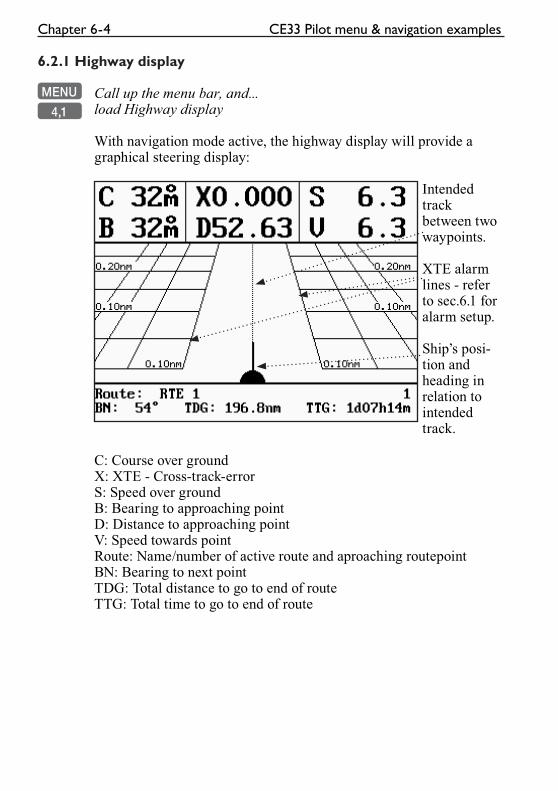
Chapter 6-4 CE33 Pilot menu & navigation examples
6.2.1 Highway display
MENU Call up the menu bar, and...
4,1 load Highway display
With navigation mode active, the highway display will provide a graphical steering display:
Intended track between two waypoints.
XTE alarm lines - refer to sec.6.1 for alarm setup.
Ship’s posi-tion and heading in relation to intended track.
C: Course over groundX: XTE - Cross-track-errorS: Speed over groundB: Bearing to approaching pointD: Distance to approaching pointV: Speed towards pointRoute: Name/number of active route and aproaching routepointBN: Bearing to next pointTDG: Total distance to go to end of routeTTG: Total time to go to end of route
CE33 Pilot menu & navigation examples Chapter 6-5
6.2.2 Navigation setup
If you wish to make any changes in the navigation setup, you can quickly enter the navigation setup display by pressing [ENT] from the highway display (graphical steering display).
ENT Quick access to navigation setup from active highway display, or...-refer to display example and description of functions in section 6.1.
6.2.3 Pilot mode - Turn NAV off
MENU Call up the menu bar, and...
4,2 turn off navigation mode
6.2.4 Pilot mode - Waypoint advance
MENU Call up the menu bar, and...
4,3 activate shift to next waypoint-it will require that navigation mode is active and that “a next way-point” exists.
6.2.5 Pilot mode - Restart to approaching point
MENU Call up the menu bar, and...
4,4 activate restart to approaching point-if you for some reason have drifted off course and wish to restart navigation from your actual position to the approaching point.
6.2.6 Pilot mode - ETA & AVN
MENU Call up the menu bar, and...
4,5 load the ETA & AVN display-it will require that navigation mode is active - see display example next page.
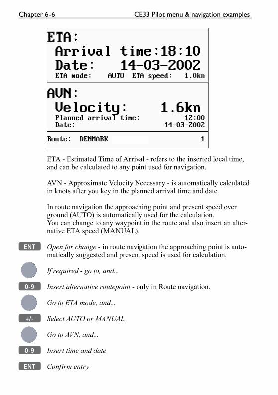
Chapter 6-6 CE33 Pilot menu & navigation examples
ETA - Estimated Time of Arrival - refers to the inserted local time, and can be calculated to any point used for navigation.
AVN - Approximate Velocity Necessary - is automatically calculated in knots after you key in the planned arrival time and date.
In route navigation the approaching point and present speed over ground (AUTO) is automatically used for the calculation.You can change to any waypoint in the route and also insert an alter-native ETA speed (MANUAL).
ENT Open for change - in route navigation the approaching point is auto-matically suggested and present speed is used for calculation.
If required - go to, and...
0-9 Insert alternative routepoint - only in Route navigation.
Go to ETA mode, and...
+/- Select AUTO or MANUAL
Go to AVN, and...
0-9 Insert time and date
ENT Confirm entry
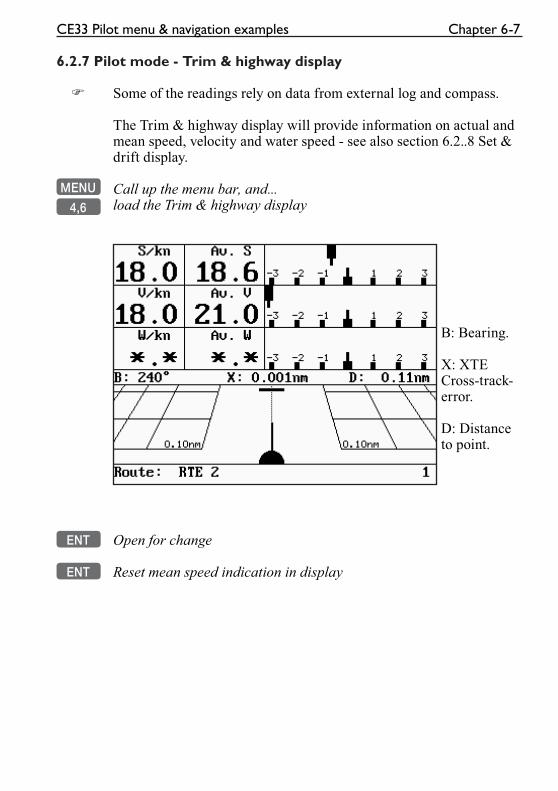
CE33 Pilot menu & navigation examples Chapter 6-7
6.2.7 Pilot mode - Trim & highway display
� Some of the readings rely on data from external log and compass.
The Trim & highway display will provide information on actual and mean speed, velocity and water speed - see also section 6.2..8 Set & drift display.
MENU Call up the menu bar, and...
4,6 load the Trim & highway display
B: Bearing.
X: XTE Cross-track-error.
D: Distance to point.
ENT Open for change
ENT Reset mean speed indication in display
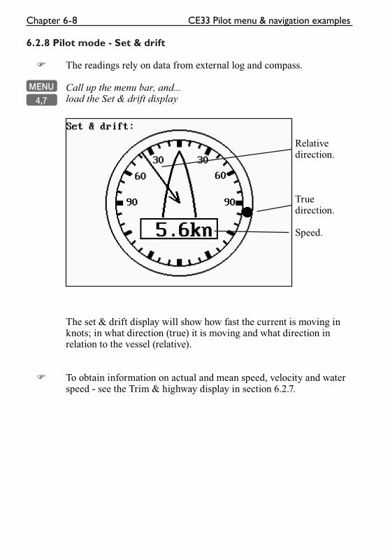
Chapter 6-8 CE33 Pilot menu & navigation examples
6.2.8 Pilot mode - Set & drift
� The readings rely on data from external log and compass.
MENU Call up the menu bar, and...
4,7 load the Set & drift display
Relative direction.
True direction.
Speed.
The set & drift display will show how fast the current is moving in knots; in what direction (true) it is moving and what direction in relation to the vessel (relative).
� To obtain information on actual and mean speed, velocity and water speed - see the Trim & highway display in section 6.2.7.
CE33 Pilot menu & navigation examples Chapter 6-9
6.3 Anchor guard
MENU Call up the menu bar, and...
4,5 activate the anchor guard function-the chart display will provide an impression of the vessel’s position in relation to the alarm circle.
To check/change the preset alarm distance:MENU Call up the menu bar, and...
4,1 load the highway display
ENT enter the navigation setup display
Move cursor to the Anchor alarm distance
0-9 Enter new value with numeric keys
ENT Confirm the change
To turn Anchor guard off again:
MENU Call up the menu bar, and...
4,2 turn anchor guard off
6.4 MOB alarm and navigation
The MOB - Man overboard - alarm and display will be activated if you press the [MOB] key on the CE33 keypad and hold it depressed for two seconds, or activate an external MOB switch (hold two sec-onds). The MOB display will provide all relevant data for an effi-cient rescue operation - refer to details on the rear of the front page.
To turn the MOB function off again:MENU Call up the menu bar, and...
4,2 turn the MOB function off
To check the last activated MOB position:MENU Call up the menu bar, and...
6,2 select MOB position
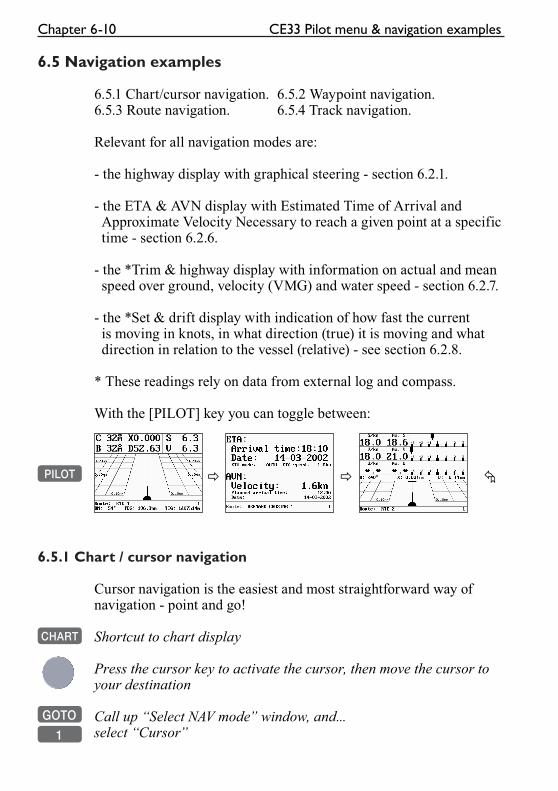
Chapter 6-10 CE33 Pilot menu & navigation examples
6.5 Navigation examples
6.5.1 Chart/cursor navigation. 6.5.2 Waypoint navigation.6.5.3 Route navigation. 6.5.4 Track navigation.
Relevant for all navigation modes are:
- the highway display with graphical steering - section 6.2.1.
- the ETA & AVN display with Estimated Time of Arrival and Approximate Velocity Necessary to reach a given point at a specific time - section 6.2.6.
- the *Trim & highway display with information on actual and mean speed over ground, velocity (VMG) and water speed - section 6.2.7.
- the *Set & drift display with indication of how fast the current is moving in knots, in what direction (true) it is moving and what direction in relation to the vessel (relative) - see section 6.2.8.
* These readings rely on data from external log and compass.
With the [PILOT] key you can toggle between:
PILOT � � �
6.5.1 Chart / cursor navigation
Cursor navigation is the easiest and most straightforward way of navigation - point and go!
CHART Shortcut to chart display
Press the cursor key to activate the cursor, then move the cursor to your destination
GOTO Call up “Select NAV mode” window, and...
1 select “Cursor”
CE33 Pilot menu & navigation examples Chapter 6-11
A course line will now be drawn from actual position (ship’s posi-tion) to destination point (cursor’s position).
Next destination: While on the way, you can easily move the cursor to the next destination, and when ready to change navigation leg...
GOTO Press [GOTO] and [2] to...
2 “Restart to approaching point”- a new course line will be drawn from ship’s position to destination.
To turn NAV mode off again:
GOTO Press [GOTO] and [3] to...
3 “Turn NAV off” from active chart display
or...
MENU Press [MENU] and [4], [2] to...
4,2 “Turn NAV off” via the menu
6.5.2 Waypoint navigation
There are two ways of activating Waypoint navigation:From the chart display using [GOTO] or from the menu system.
From the chart:CHART Shortcut to chart display
Place cursor on destination waypoint
GOTO Select NAV mode, and...
2 Select Waypoint
This will activate the pop-up window “Navigate to WP” - now follow the procedures from the � a few lines further ahead, or press [ENT] to start navigation.
Chapter 6-12 CE33 Pilot menu & navigation examples
From the menu:MENU Call up the menu bar, and...
4,2 select Waypoint navigation
� This will activate the pop-up window “Navigate to WP” from where you can choose which waypoint you wish to sail to:
Use the cursor to scroll up/down in the waypoint list, or place cursor on the WP number, and...
+/- Scroll up/down with +/- keys, or...
0-9 Key in the number of the waypoint you wish to sail to
ENT Start navigation
A course line will now be drawn from ship’s position to destination waypoint.
To turn NAV mode off again:
GOTO Press [GOTO] and [3] to...
3 “Turn NAV off” from active chart display
or...
MENU Press [MENU] and [4], [2] to...
4,2 “Turn NAV off” via the menu
CE33 Pilot menu & navigation examples Chapter 6-13
6.5.3 Route navigation
To start Route navigation will require that at least one route is stored in the memory. Refer to section 3.3.9 PLOT function.
When navigating in a route, you will have a graphical steering dis-play to navigate by, see section 6.2.1. Know your ETA - Estimated Time of Arrival, and your AVN - Average Velocity Necessary, see section 6.2.6. Call up the Set & drift display, see section 6.2.8.
There are two ways of activating Route navigation:From the chart display using [GOTO] or from the menu system.
From the chart:CHART Shortcut to chart display
Place cursor on the routepoint you wish to start your navigation from
GOTO Select NAV mode, and...
3 Select Route
This will activate the pop-up window “Navigate in route” with the selected routepoint as first destination - now follow the procedures from the � a few lines further ahead, or press [ENT] to start naviga-tion.
From the menu:MENU Call up the menu bar, and...
4,3 select Route navigation
� This will activate the pop-up window “Navigate in route” from where you can choose which route you wish to select for navigation:
+/- Scroll up/down in the route list until the correct route number / name appears
Use the cursor to move around in the window if anything needs to be changed - such as Direction in route, etc.
0-9 Key in the number of the first routepoint you wish to sail to
Chapter 6-14 CE33 Pilot menu & navigation examples
ENT Start navigation
A course line will now be drawn from ship’s position to the first routepoint.
GOTO Pressing [GOTO] from chart display during navigation will activate an INFO window with the following functions to choose from:1. Advance (to next routepoint)2. Restart to approaching point (in case you have drifted off course)3. Turn NAV OFF
MENU Pressing [MENU] and [4] from an active data display during naviga-
4 tion will give access to the following displays / features:1. Highway2. Turn NAV off3. WP advance (to next routepoint)4. Restart to approaching point (in case you have drifted off course)5. ETA & AVN6. Trim & highway7. Set & drift
CE33 Pilot menu & navigation examples Chapter 6-15
6.5.4 Track navigation
A track is created by a series of trackpoints connected by track lines. Using a track for navigation is somewhat like navigating in a route with many waypoints.
� To start Track navigation will require that at least one track is stored in the memory. Tracks which are not yet completed can not be used for navigation. Refer to section 5.5 Start / Stop track.
When navigating in a track, you can use the chart or the Highway display to navigate by, see section 6.2.1. Know your ETA - Estimated Time of Arrival, and your AVN - Average Velocity Necessary, see section 6.2.6. Call up the Set & drift display, see section 6.2.8.
There are two ways of activating Track navigation:From the chart display using [GOTO] or from the menu system.
From the chart:CHART Shortcut to chart display
Place cursor on the track at the point where you wish to start your navigation from
GOTO Select NAV mode, and...
4 Select Track
This will activate the pop-up window “Navigate in track” - now follow the procedures from the � a few lines further ahead, or press [ENT] to start navigation.
From the menu:MENU Call up the menu bar, and...
4,4 select Track navigation
� This will activate the pop-up window “Navigate in track” from where you can choose which track you wish to select for navigation:
+/- Scroll up/down in the track list until the correct track number / name appears
Chapter 6-16 CE33 Pilot menu & navigation examples
Use the cursor to move around in the window if anything needs to be changed - such as Direction in track, etc.
0-9 Key in the number of the first trackpoint you wish to sail to
ENT Start navigation
A course line will now be drawn from ship’s position to the first point of destination.
GOTO Pressing [GOTO] from chart display during navigation will activate an INFO window with the following functions to choose from:1. Advance (to next trackpoint)2. Restart to approaching point (in case you have drifted off course)3. Turn NAV OFF
MENU Pressing [MENU] and [4] from an active data display during naviga-
4 tion will give access to the following displays / features:1. Highway2. Turn NAV off3. WP advance (to next trackpoint)4. Restart to approaching point (in case you have drifted off course)5. ETA & AVN6. Trim & highway7. Set & drift
CE33 Echosounder operation Chapter 7-1
7. Echosounder operation
The echosounder function of the CE33 determines the distance between its transducer and underwater objects such as fish, lake bottom or sea bed. It does this by utilizing the fact that an ultrasonic wave transmitted through water travels at a nearly constant speed of 4800 feet (1500 meters) per second. When a sound wave strikes an underwater object such as fish or sea bottom, part of the sound wave is reflected back toward the source. Thus by calculating the time difference between the transmission of a sound wave and the reception of the reflected sound wave, the depth to the object can be determined.
The entire process begins in the display unit. Transmitter power is sent to the transducer as a short pulse of electrical energy. The elec-trical signal produced by the transmitter is converted into an ultra-sonic signal by the transducer and transmitted into the water. Any reflected signals from intervening objects (such as a fish school) are received by the transducer and converted back into an electri-cal signal. It is then amplified in the amplifier section, and finally, displayed on the screen.
The picture displayed is made up of a series of vertical scan lines (pings), one for each transmission. Each line represents a ‘snapshot’ of what has occurred beneath the boat. The series of snapshots are accumulated side by side across the screen, and the resulting con-tours of the bottom and fish between the bottom and surface are displayed.
Selecting echosounder displaysThe CE33 provides various types of echosounder displays: standard echogram, A-scope, bottom expansion (zoom) and VRM expan-sion. Each display has its special advantages. Select the appropriate setup for the echosounder display in the presentation “Setup” and “Echosounder setup” displays, considering current sea area and target fish.
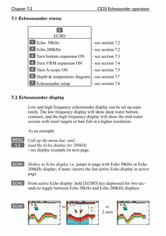
Chapter 7-2 CE33 Echosounder operation
7.1 Echosounder menu
5
ECHO
1 Echo 50kHz - see section 7.2
2 Echo 200kHz - see section 7.2
3 Turn bottom expansion ON - see section 7.3
4 Turn VRM expansion ON - see section 7.4
5 Turn A-scope ON - see section 7.5
6 Depth & temperature diagram - see section 7.7
7 Echosounder setup - see section 7.8
7.2 Echosounder display
Low and high frequency echosounder display can be set up sepa-rately. The low frequency display will show deep water bottom contours, and the high frequency display will show the mid-water section with trawl targets or bait fish in a higher resolution.
As an example:
MENU Call up the menu bar, and...5,2 load the Echo display for 200kHz
- see display example on next page.
ECHO Hotkey to Echo display i.e. jumps to page with Echo 50kHz or Echo 200kHz display; if none: inserts the last active Echo display in active page.
ECHO From active Echo display: hold [ECHO] key depressed for two sec-onds to toggle between Echo 50kHz and Echo 200kHz displays.
ECHO � �
2 secs.
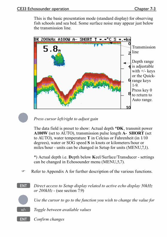
CE33 Echosounder operation Chapter 7-3
This is the basic presentation mode (standard display) for observing fish schools and sea bed. Some surface noise may appear just below the transmission line.
Transmission line
Depth range is adjustable with +/- keys or the Quick-range keys 1-9. Press key 0 to return to Auto range.
Press cursor left/right to adjust gain
The data field is preset to show: Actual depth *DK, transmit power A100W (set to AUTO), transmission pulse length A- SHORT (set to AUTO), water temperature T in Celcius or Fahrenheit (in 1/10 degrees), water or SOG speed S in knots or kilometers/hour or miles/hour - units can be changed in Setup for units (MENU,7,1).
*) Actual depth i.e. Depth below Keel/Surface/Transducer - settings can be changed in Echosounder menu (MENU,5,7).
� Refer to Appendix A for further description of the various functions.
ENT Direct access to Setup display related to active echo display 50kHz or 200kHz - (see section 7.9)
Use the cursor to go to the function you wish to change the value for
+/- Toggle between available values
ENT Confirm changes
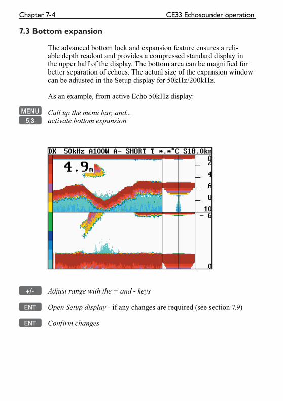
Chapter 7-4 CE33 Echosounder operation
7.3 Bottom expansion
The advanced bottom lock and expansion feature ensures a reli-able depth readout and provides a compressed standard display in the upper half of the display. The bottom area can be magnified for better separation of echoes. The actual size of the expansion window can be adjusted in the Setup display for 50kHz/200kHz.
As an example, from active Echo 50kHz display:
MENU Call up the menu bar, and...5,3 activate bottom expansion
+/- Adjust range with the + and - keys
ENT Open Setup display - if any changes are required (see section 7.9)
ENT Confirm changes
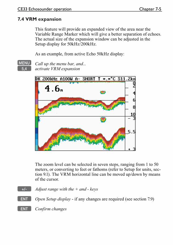
CE33 Echosounder operation Chapter 7-5
7.4 VRM expansion
This feature will provide an expanded view of the area near the Variable Range Marker which will give a better separation of echoes. The actual size of the expansion window can be adjusted in the Setup display for 50kHz/200kHz.
As an example, from active Echo 50kHz display:
MENU Call up the menu bar, and...5,4 activate VRM expansion
The zoom level can be selected in seven steps, ranging from 1 to 50 meters, or converting to feet or fathoms (refer to Setup for units, sec-tion 9.1). The VRM horizontal line can be moved up/down by means of the cursor.
+/- Adjust range with the + and - keys
ENT Open Setup display - if any changes are required (see section 7.9)
ENT Confirm changes
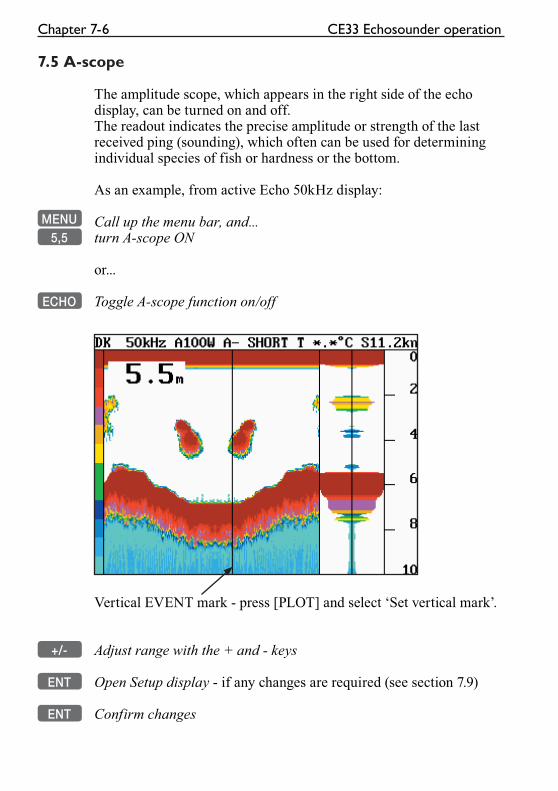
Chapter 7-6 CE33 Echosounder operation
7.5 A-scope
The amplitude scope, which appears in the right side of the echo display, can be turned on and off.The readout indicates the precise amplitude or strength of the last received ping (sounding), which often can be used for determining individual species of fish or hardness or the bottom.
As an example, from active Echo 50kHz display:
MENU Call up the menu bar, and...5,5 turn A-scope ON
or...
ECHO Toggle A-scope function on/off
Vertical EVENT mark - press [PLOT] and select ‘Set vertical mark’.
+/- Adjust range with the + and - keys
ENT Open Setup display - if any changes are required (see section 7.9)
ENT Confirm changes
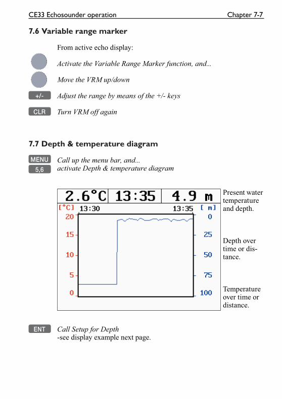
CE33 Echosounder operation Chapter 7-7
7.6 Variable range marker
From active echo display:
Activate the Variable Range Marker function, and...
Move the VRM up/down
+/- Adjust the range by means of the +/- keys
CLR Turn VRM off again
7.7 Depth & temperature diagram
MENU Call up the menu bar, and...
5,6 activate Depth & temperature diagram
Present water temperature and depth.
Depth over time or dis-tance.
Temperature over time or distance.
ENT Call Setup for Depth -see display example next page.
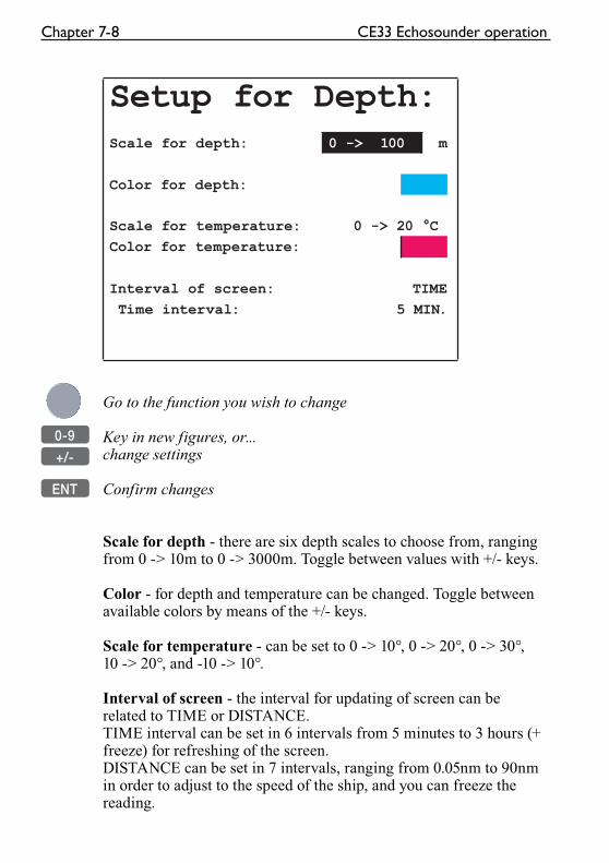
Chapter 7-8 CE33 Echosounder operation
Setup for Depth:Scale for depth: 0 -> 100 m
Color for depth:
Scale for temperature: 0 -> 20 °C
Color for temperature:
Interval of screen: TIME
Time interval: 5 MIN.
Go to the function you wish to change
0-9 Key in new figures, or...
+/- change settings
ENT Confirm changes
Scale for depth - there are six depth scales to choose from, ranging from 0 -> 10m to 0 -> 3000m. Toggle between values with +/- keys.
Color - for depth and temperature can be changed. Toggle between available colors by means of the +/- keys.
Scale for temperature - can be set to 0 -> 10°, 0 -> 20°, 0 -> 30°, 10 -> 20°, and -10 -> 10°.
Interval of screen - the interval for updating of screen can be related to TIME or DISTANCE.TIME interval can be set in 6 intervals from 5 minutes to 3 hours (+ freeze) for refreshing of the screen.DISTANCE can be set in 7 intervals, ranging from 0.05nm to 90nm in order to adjust to the speed of the ship, and you can freeze the reading.
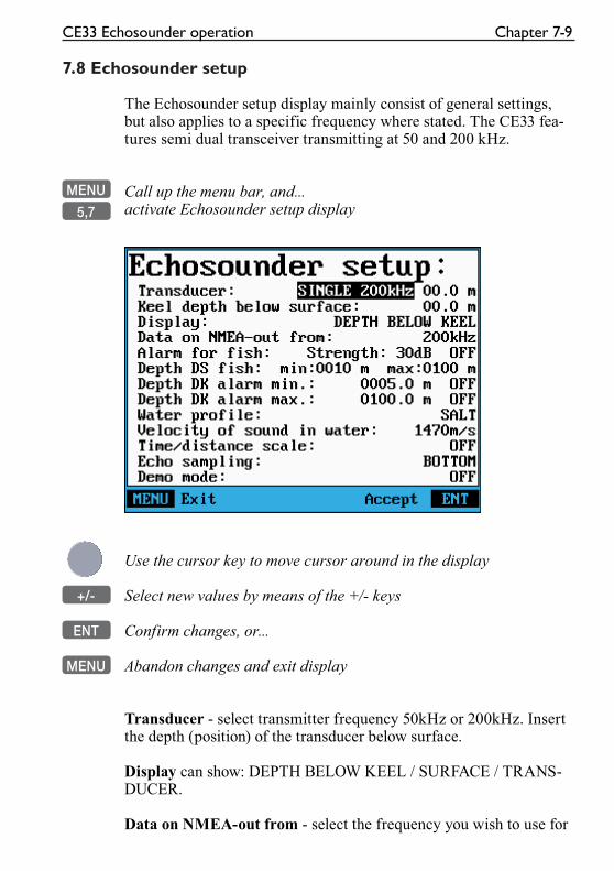
CE33 Echosounder operation Chapter 7-9
7.8 Echosounder setup
The Echosounder setup display mainly consist of general settings, but also applies to a specific frequency where stated. The CE33 fea-tures semi dual transceiver transmitting at 50 and 200 kHz.
MENU Call up the menu bar, and...
5,7 activate Echosounder setup display
Use the cursor key to move cursor around in the display
+/- Select new values by means of the +/- keys
ENT Confirm changes, or...
MENU Abandon changes and exit display
Transducer - select transmitter frequency 50kHz or 200kHz. Insert the depth (position) of the transducer below surface.
Display can show: DEPTH BELOW KEEL / SURFACE / TRANS-DUCER.
Data on NMEA-out from - select the frequency you wish to use for
Chapter 7-10 CE33 Echosounder operation
transfer of data to connected navigator, plotter, etc.
Alarm for fish - set the strength from min. 00 (weak echo) to max. 99dB (strong echo), and you can set it ON or OFF.
Depth DS fish - define a specific area below the water surface of minimum and maximum depth for the fish alarm.
Depth DK alarm min. and max. - set up a depth limit alarm for depth below keel.
Water profile - choose between SALT and FRESH water. The set-ting will reflect on the:
Velocity of sound in water: SALT = 1470 meters per second and FRESH = 1430 meters per second as standard. The standard set-tings can be even more accurate by slightly increasing the number of meters in warm waters and decreasing in cold waters.
Time/distance scale - will indicate the elapsed time or distance for the echo picture. The readout will appear in the upper part of the echo display. Toggle between time and distance in “Scroll synchro-nisation”, section 7.9.
Echo sampling - is preset to BOTTOM, which enables auto range and a view all the way to the bottom. In RANGE the unit will not wait for a bottom echo, but transmit a new pulse as soon as the selected range has been reached. This mode will often improve bottom detection and digital depth readout for vessels moving at higher speeds. Also, it will enable a more detailed search for fish in midwater range. Auto range is automatically switched off. The depth alarm setting will have a higher priority than the selected depth range.
Demo mode - the echosounder will function as though a transducer was connected, but all data presented in the display will be simu-lated.
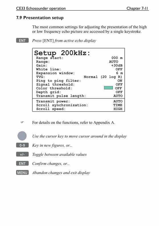
CE33 Echosounder operation Chapter 7-11
7.9 Presentation setup
The most common settings for adjusting the presentation of the high or low frequency echo picture are accessed by a single keystroke.
ENT Press [ENT] from active echo display
Setup 200kHz: Range start: 000 m Range: AUTO Gain: +30dB White line: OFF Expansion window: 6 m TVG: Normal (20 log R) Ping to ping filter: ON Signal threshold: OFF Color threshold: OFF Depth grid: OFF Transmit pulse length: AUTO
Transmit power: AUTO Scroll synchronization: TIME Scroll speed: HIGH
� For details on the functions, refer to Appendix A.
Use the cursor key to move cursor around in the display
0-9 Key in new figures, or...
+/- Toggle between available values
ENT Confirm changes, or...
MENU Abandon changes and exit display
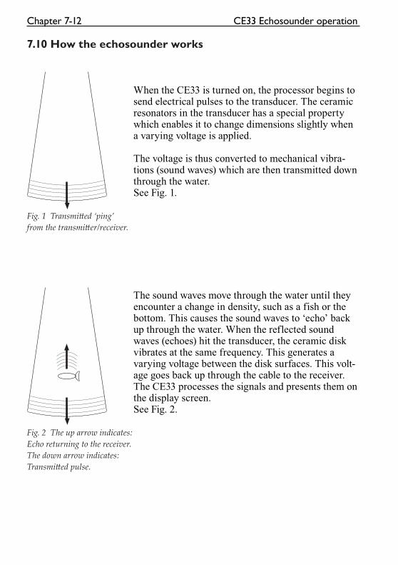
Chapter 7-12 CE33 Echosounder operation
7.10 How the echosounder works
When the CE33 is turned on, the processor begins to send electrical pulses to the transducer. The ceramic resonators in the transducer has a special property which enables it to change dimensions slightly when a varying voltage is applied.
The voltage is thus converted to mechanical vibra-tions (sound waves) which are then transmitted down through the water. See Fig. 1.
Fig. 1 Transmi� ed ‘ping’
from the transmi� er/receiver.
The sound waves move through the water until they encounter a change in density, such as a fish or the bottom. This causes the sound waves to ‘echo’ back up through the water. When the reflected sound waves (echoes) hit the transducer, the ceramic disk vibrates at the same frequency. This generates a varying voltage between the disk surfaces. This volt-age goes back up through the cable to the receiver.The CE33 processes the signals and presents them on the display screen. See Fig. 2.
Fig. 2 The up arrow indicates:
Echo returning to the receiver.
The down arrow indicates:
Transmi� ed pulse.
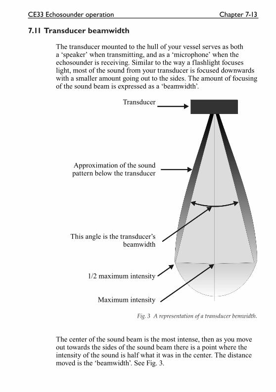
CE33 Echosounder operation Chapter 7-13
7.11 Transducer beamwidth
The transducer mounted to the hull of your vessel serves as both a ‘speaker’ when transmitting, and as a ‘microphone’ when the echosounder is receiving. Similar to the way a flashlight focuses light, most of the sound from your transducer is focused downwards with a smaller amount going out to the sides. The amount of focusing of the sound beam is expressed as a ‘beamwidth’.
Transducer
Approximation of the sound pattern below the transducer
This angle is the transducer’s beamwidth
1/2 maximum intensity
Maximum intensity
Fig. 3 A representation of a transducer bemwidth.
The center of the sound beam is the most intense, then as you move out towards the sides of the sound beam there is a point where the intensity of the sound is half what it was in the center. The distance moved is the ‘beamwidth’. See Fig. 3.

Chapter 7-14 CE33 Echosounder operation
7.12 Effects of the vessel’s speed
The presentation of fish on the CE33 depends directly on the vessel’s speed, as well as on the depth of the fish. When the vessel is at rest, the echo traces will appear stretched and flattened. As the vessel’s speed becomes greater, the echo traces will become shorter and more arched. The reason for this change in appearance is that as the vessel speed increases, fewer number of sound ‘pings’ strike each fish. A low vessel speed will provide the most accurate information of where fish are loacted.
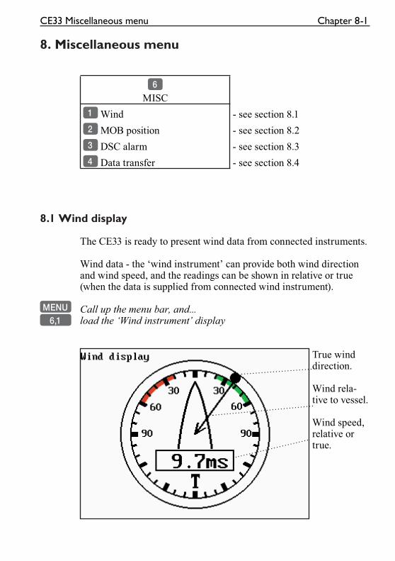
CE33 Miscellaneous menu Chapter 8-1
8. Miscellaneous menu
6
MISC
1 Wind - see section 8.1
2 MOB position - see section 8.2
3 DSC alarm - see section 8.3
4 Data transfer - see section 8.4
8.1 Wind display
The CE33 is ready to present wind data from connected instruments.
Wind data - the ‘wind instrument’ can provide both wind direction and wind speed, and the readings can be shown in relative or true (when the data is supplied from connected wind instrument).
MENU Call up the menu bar, and...6,1 load the ‘Wind instrument’ display
True wind direction.
Wind rela-tive to vessel.
Wind speed, relative or true.
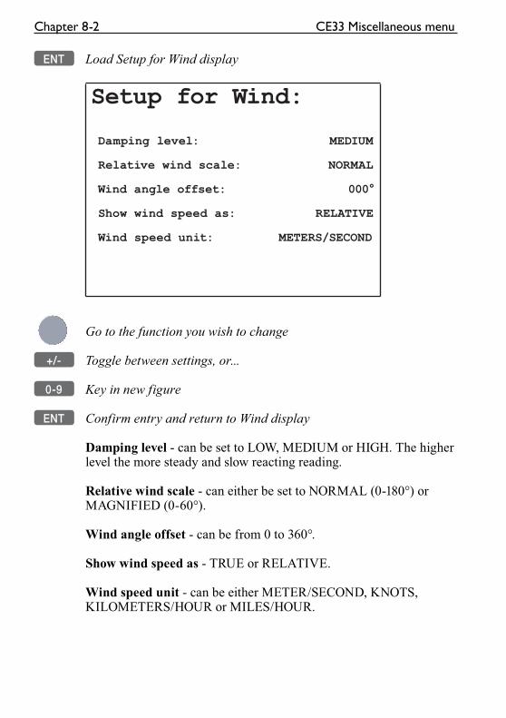
Chapter 8-2 CE33 Miscellaneous menu
ENT Load Setup for Wind display
Setup for Wind:
Damping level: MEDIUM
Relative wind scale: NORMAL
Wind angle offset: 000°
Show wind speed as: RELATIVE
Wind speed unit: METERS/SECOND
Go to the function you wish to change
+/- Toggle between settings, or...
0-9 Key in new figure
ENT Confirm entry and return to Wind display
Damping level - can be set to LOW, MEDIUM or HIGH. The higher level the more steady and slow reacting reading.
Relative wind scale - can either be set to NORMAL (0-180°) or MAGNIFIED (0-60°).
Wind angle offset - can be from 0 to 360°.
Show wind speed as - TRUE or RELATIVE.
Wind speed unit - can be either METER/SECOND, KNOTS, KILOMETERS/HOUR or MILES/HOUR.
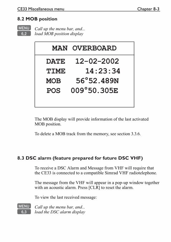
CE33 Miscellaneous menu Chapter 8-3
8.2 MOB position
MENU Call up the menu bar, and...6,2 load MOB position display
MAN OVERBOARD
DATE 12-02-2002 TIME 14:23:34 MOB 56°52.489N POS 009°50.305E
The MOB display will provide information of the last activated MOB position.
To delete a MOB track from the memory, see section 3.3.6.
8.3 DSC alarm (feature prepared for future DSC VHF)
To receive a DSC Alarm and Message from VHF will require that the CE33 is connected to a compatible Simrad VHF radiotelephone.
The message from the VHF will appear in a pop-up window together with an acoustic alarm. Press [CLR] to reset the alarm.
To view the last received message:
MENU Call up the menu bar, and...6,3 load the DSC alarm display
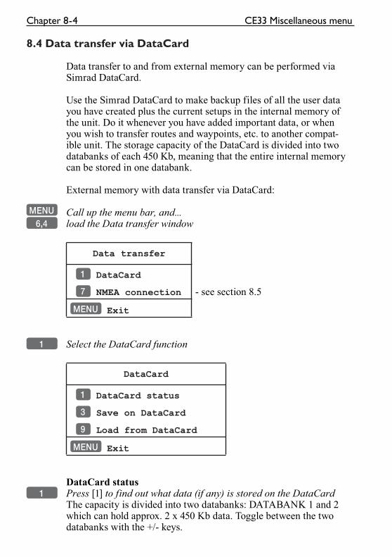
Chapter 8-4 CE33 Miscellaneous menu
8.4 Data transfer via DataCard
Data transfer to and from external memory can be performed via Simrad DataCard.
Use the Simrad DataCard to make backup files of all the user data you have created plus the current setups in the internal memory of the unit. Do it whenever you have added important data, or when you wish to transfer routes and waypoints, etc. to another compat-ible unit. The storage capacity of the DataCard is divided into two databanks of each 450 Kb, meaning that the entire internal memory can be stored in one databank.
External memory with data transfer via DataCard:
MENU Call up the menu bar, and...6,4 load the Data transfer window
Data transfer
1 DataCard
7 NMEA connection - see section 8.5
MENU Exit
1 Select the DataCard function
DataCard
1 DataCard status
3 Save on DataCard
9 Load from DataCard
MENU Exit
DataCard status1 Press [1] to find out what data (if any) is stored on the DataCard
The capacity is divided into two databanks: DATABANK 1 and 2 which can hold approx. 2 x 450 Kb data. Toggle between the two databanks with the +/- keys.
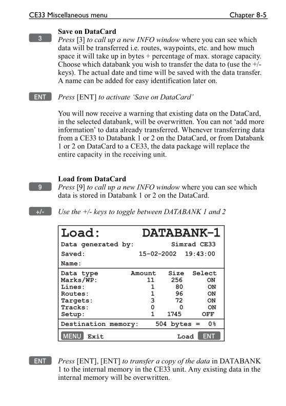
CE33 Miscellaneous menu Chapter 8-5
Save on DataCard3 Press [3] to call up a new INFO window where you can see which
data will be transferred i.e. routes, waypoints, etc. and how much space it will take up in bytes + percentage of max. storage capacity. Choose which databank you wish to transfer the data to (use the +/- keys). The actual date and time will be saved with the data transfer. A name can be added for easy identification later on.
ENT Press [ENT] to activate ‘Save on DataCard’
You will now receive a warning that existing data on the DataCard, in the selected databank, will be overwritten. You can not ‘add more information’ to data already transferred. Whenever transferring data from a CE33 to Databank 1 or 2 on the DataCard, or from Databank 1 or 2 on DataCard to a CE33, the data package will replace the entire capacity in the receiving unit.
Load from DataCard9 Press [9] to call up a new INFO window where you can see which
data is stored in Databank 1 or 2 on the DataCard.
+/- Use the +/- keys to toggle between DATABANK 1 and 2
Load: DATABANK-1Data generated by: Simrad CE33
Saved: 15-02-2002 19:43:00
Name:
Data type Amount Size SelectMarks/WP: 11 256 ONLines: 1 80 ONRoutes: 1 96 ONTargets: 3 72 ONTracks: 0 0 ONSetup: 1 1745 OFF
Destination memory: 504 bytes = 0%
MENU Exit Load ENT
ENT Press [ENT], [ENT] to transfer a copy of the data in DATABANK 1 to the internal memory in the CE33 unit. Any existing data in the internal memory will be overwritten.
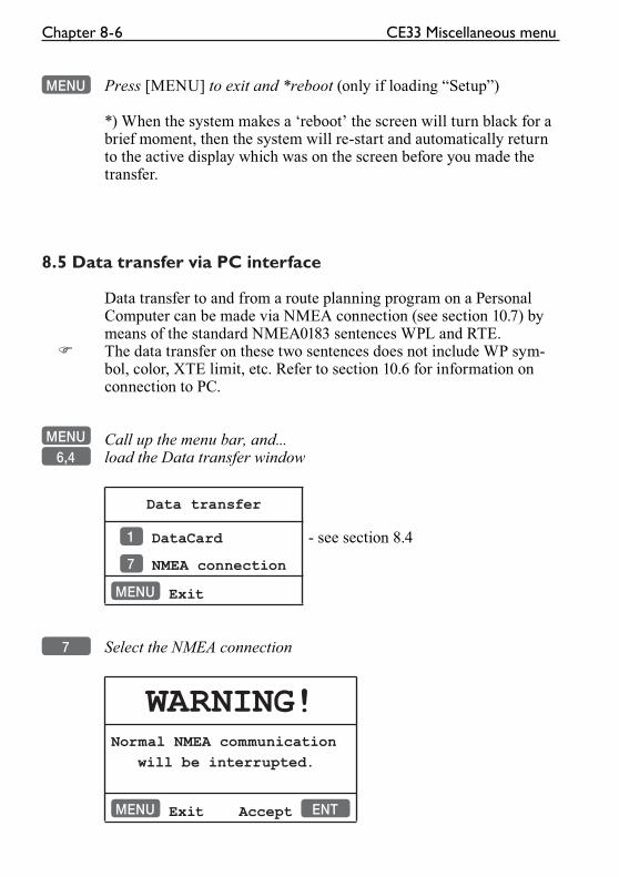
Chapter 8-6 CE33 Miscellaneous menu
MENU Press [MENU] to exit and *reboot (only if loading “Setup”)
*) When the system makes a ‘reboot’ the screen will turn black for a brief moment, then the system will re-start and automatically return to the active display which was on the screen before you made the transfer.
8.5 Data transfer via PC interface
Data transfer to and from a route planning program on a Personal Computer can be made via NMEA connection (see section 10.7) by means of the standard NMEA0183 sentences WPL and RTE.
� The data transfer on these two sentences does not include WP sym-bol, color, XTE limit, etc. Refer to section 10.6 for information on connection to PC.
MENU Call up the menu bar, and...6,4 load the Data transfer window
Data transfer
1 DataCard - see section 8.4
7 NMEA connection
MENU Exit
7 Select the NMEA connection
WARNING!Normal NMEA communication
will be interrupted.
MENU Exit Accept ENT
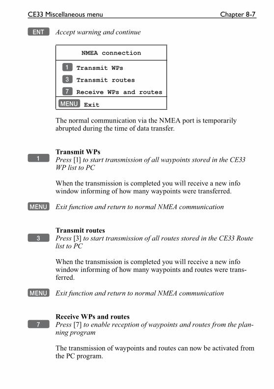
CE33 Miscellaneous menu Chapter 8-7
ENT Accept warning and continue
NMEA connection
1 Transmit WPs
3 Transmit routes
7 Receive WPs and routes
MENU Exit
The normal communication via the NMEA port is temporarily abrupted during the time of data transfer.
Transmit WPs1 Press [1] to start transmission of all waypoints stored in the CE33
WP list to PC
When the transmission is completed you will receive a new info window informing of how many waypoints were transferred.
MENU Exit function and return to normal NMEA communication
Transmit routes3 Press [3] to start transmission of all routes stored in the CE33 Route
list to PC
When the transmission is completed you will receive a new info window informing of how many waypoints and routes were trans-ferred.
MENU Exit function and return to normal NMEA communication
Receive WPs and routes7 Press [7] to enable reception of waypoints and routes from the plan-
ning program
The transmission of waypoints and routes can now be activated from the PC program.
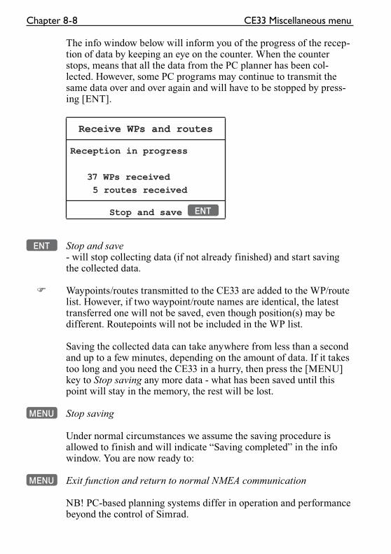
Chapter 8-8 CE33 Miscellaneous menu
The info window below will inform you of the progress of the recep-tion of data by keeping an eye on the counter. When the counter stops, means that all the data from the PC planner has been col-lected. However, some PC programs may continue to transmit the same data over and over again and will have to be stopped by press-ing [ENT].
Receive WPs and routes
Reception in progress
37 WPs received
5 routes received
Stop and save ENT
ENT Stop and save - will stop collecting data (if not already finished) and start saving the collected data.
� Waypoints/routes transmitted to the CE33 are added to the WP/route list. However, if two waypoint/route names are identical, the latest transferred one will not be saved, even though position(s) may be different. Routepoints will not be included in the WP list.
Saving the collected data can take anywhere from less than a second and up to a few minutes, depending on the amount of data. If it takes too long and you need the CE33 in a hurry, then press the [MENU] key to Stop saving any more data - what has been saved until this point will stay in the memory, the rest will be lost.
MENU Stop saving
Under normal circumstances we assume the saving procedure is allowed to finish and will indicate “Saving completed” in the info window. You are now ready to:
MENU Exit function and return to normal NMEA communication
NB! PC-based planning systems differ in operation and performance beyond the control of Simrad.
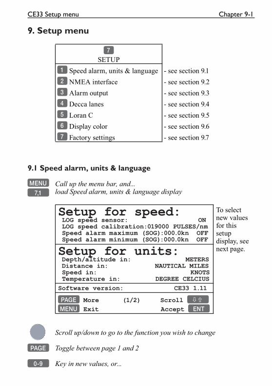
CE33 Setup menu Chapter 9-1
9. Setup menu
7
SETUP
1 Speed alarm, units & language - see section 9.1
2 NMEA interface - see section 9.2
3 Alarm output - see section 9.3
4 Decca lanes - see section 9.4
5 Loran C - see section 9.5
6 Display color - see section 9.6
7 Factory settings - see section 9.7
9.1 Speed alarm, units & language
MENU Call up the menu bar, and...
7,1 load Speed alarm, units & language display
Setup for speed: LOG speed sensor: ON LOG speed calibration:019000 PULSES/nm Speed alarm maximum (SOG):000.0kn OFF Speed alarm minimum (SOG):000.0kn OFF
To select new values for this setup display, see next page.Setup for units:
Depth/altitude in: METERS Distance in: NAUTICAL MILES Speed in: KNOTS Temperature in: DEGREE CELCIUS
Software version: CE33 1.11
PAGE More (1/2) Scroll ��
MENU Exit Accept ENT
Scroll up/down to go to the function you wish to change
PAGE Toggle between page 1 and 2
0-9 Key in new values, or...
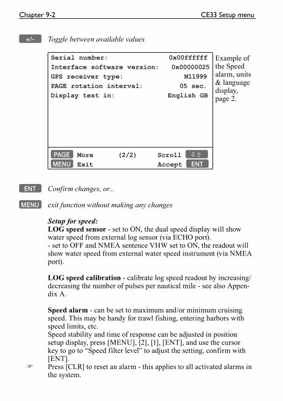
Chapter 9-2 CE33 Setup menu
+/- Toggle between available values
Serial number: 0x00ffffff
Interface software version: 0x00000025
GPS receiver type: N11999
PAGE rotation interval: 05 sec.
Display text in: English GB
Example of the Speed alarm, units & language display, page 2.
PAGE More (2/2) Scroll ��
MENU Exit Accept ENT
ENT Confirm changes, or...
MENU exit function without making any changes
Setup for speed:LOG speed sensor - set to ON, the dual speed display will show water speed from external log sensor (via ECHO port).- set to OFF and NMEA sentence VHW set to ON, the readout will show water speed from external water speed instrument (via NMEA port).
LOG speed calibration - calibrate log speed readout by increasing/decreasing the number of pulses per nautical mile - see also Appen-dix A.
Speed alarm - can be set to maximum and/or minimum cruising speed. This may be handy for trawl fishing, entering harbors with speed limits, etc.Speed stability and time of response can be adjusted in position setup display, press [MENU], [2], [1], [ENT], and use the cursor key to go to “Speed filter level” to adjust the setting, confirm with [ENT].
� Press [CLR] to reset an alarm - this applies to all activated alarms in the system.
CE33 Setup menu Chapter 9-3
Setup for units
Depth altitude in - can be set to meters (m), feet (ft) or fathoms (fm).
Distance in - can be calculated in nautical miles (nm), kilometers (km) or statue miles (mi).
Speed in - can be shown in knots (kn), kilometers/hour (kh) or miles/hour (mh).
Temperature in - can be shown in Celcius or Fahrenheit.
Software version - indicates which software version is installed in the unit.
Serial number - indicates the unit’s serial number.
Interface software version - indicates which version is installed in the unit (for technicians only).
GPS receiver type - indicates which type is installed in the unit (for technicians only).
PAGE rotation interval - can be set to anywhere between 03 to 99 seconds. Refer to “Fundamentals of the display and page system” in section 2.1 for more details on how the function works.
Display text in - as standard the CE33 is supplied with the follow-ing national display languages: Danish (DK), English (GB), English (US), French (F), German (D), Italian (I), Nederlands (NL), Spanish (E), Swedish (S), and Portuguese (P).
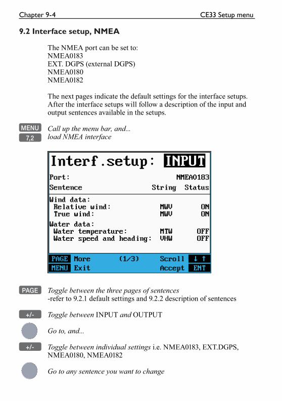
Chapter 9-4 CE33 Setup menu
9.2 Interface setup, NMEA
The NMEA port can be set to:NMEA0183EXT. DGPS (external DGPS)NMEA0180NMEA0182
The next pages indicate the default settings for the interface setups. After the interface setups will follow a description of the input and output sentences available in the setups.
MENU Call up the menu bar, and...
7,2 load NMEA interface
PAGE Toggle between the three pages of sentences -refer to 9.2.1 default settings and 9.2.2 description of sentences
+/- Toggle between INPUT and OUTPUT
Go to, and...
+/- Toggle between individual settings i.e. NMEA0183, EXT.DGPS, NMEA0180, NMEA0182
Go to any sentence you want to change
CE33 Setup menu Chapter 9-5
+/- Toggle between values, and between ON and OFF
ENT Confirm entry, and accept warning (press [ENT] again), or...
MENU exit function without making any changes
9.2.1 Default sentences
Interface setup - INPUT - Port NMEA0183:
Sentence String Status
Wind data: Relative wind: MWV ON True wind: MWV ON
Water data: Water temperature: MTW OFF Water speed and heading: VHW OFF-----------------------------------------------Heading data: Heading: HDG ON
Position data: External pos data: OFF Datum: 000 Name: World Geodetic System 1984 Position: GLL ON Course: VTG ON Speed: VTG ON
Waypoint data: Waypoint location: WPL ON-----------------------------------------------Target data: Target Lat/Lon: TLL OFF-----------------------------------------------
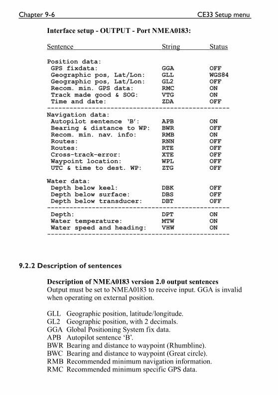
Chapter 9-6 CE33 Setup menu
Interface setup - OUTPUT - Port NMEA0183:
Sentence String Status
Position data: GPS fixdata: GGA OFF Geographic pos, Lat/Lon: GLL WGS84 Geographic pos, Lat/Lon: GL2 OFF Recom. min. GPS data: RMC ON Track made good & SOG: VTG ON Time and date: ZDA OFF-------------------------------------------------Navigation data: Autopilot sentence ‘B’: APB ON Bearing & distance to WP: BWR OFF Recom. min. nav. info: RMB ON Routes: RNN OFF Routes: RTE OFF Cross-track-error: XTE OFF Waypoint location: WPL OFF UTC & time to dest. WP: ZTG OFF
Water data: Depth below keel: DBK OFF Depth below surface: DBS OFF Depth below transducer: DBT OFF------------------------------------------------- Depth: DPT ON Water temperature: MTW ON Water speed and heading: VHW ON-------------------------------------------------
9.2.2 Description of sentences
Description of NMEA0183 version 2.0 output sentencesOutput must be set to NMEA0183 to receive input. GGA is invalid when operating on external position.
GLL Geographic position, latitude/longitude.GL2 Geographic position, with 2 decimals.GGA Global Positioning System fix data.APB Autopilot sentence ‘B’.BWR Bearing and distance to waypoint (Rhumbline).BWC Bearing and distance to waypoint (Great circle).RMB Recommended minimum navigation information.RMC Recommended minimum specific GPS data.
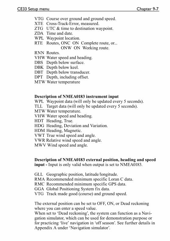
CE33 Setup menu Chapter 9-7
VTG Course over ground and ground speed.XTE Cross-Track-Error, measured.ZTG UTC & time to destination waypoint.ZDA Time and date.WPL Waypoint location.RTE Routes, ONC ON Complete route, or... ONW ON Working route.RNN Routes.VHW Water speed and heading.DBS Depth below surface.DBK Depth below keel.DBT Depth below transducer.DPT Depth, including offset.MTW Water temperature
Description of NMEA0183 instrument inputWPL Waypoint data (will only be updated every 5 seconds).TLL Target data (will only be updated every 5 seconds).MTW Water temperature.VHW Water speed and heading.HDT Heading, True.HDG Heading, Deviation and Variation.HDM Heading, Magnetic.VWT True wind speed and angle.VWR Relative wind speed and angle.MWV Wind speed and angle.
Description of NMEA0183 external position, heading and speed input - Input is only valid when output is set to NMEA0183.
GLL Geographic position, latitude/longitude.RMA Recommended minimum specific Loran C data.RMC Recommended minimum specific GPS data.GGA Global Positioning System fix data.VTG Track made good (course) and ground speed.
The external position can be set to OFF, ON, or Dead reckoning where you can enter a speed value.When set to ‘Dead reckoning’, the system can function as a Navi-gation simulator, which can be used for demonstration purpose or for practicing ‘live’ navigation in ‘off season’. See further details in Appendix A under ‘Navigation simulator’.
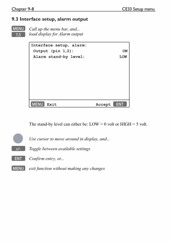
Chapter 9-8 CE33 Setup menu
9.3 Interface setup, alarm output
MENU Call up the menu bar, and...
7,3 load display for Alarm output
Interface setup, alarm:
Output (pin 1,2): ON
Alarm stand-by level: LOW
MENU Exit Accept ENT
The stand-by level can either be: LOW = 0 volt or HIGH = 5 volt.
Use cursor to move around in display, and...
+/- Toggle between available settings
ENT Confirm entry, or...
MENU exit function without making any changes

CE33 Setup menu Chapter 9-9
9.4 Decca lanes
MENU Call up the menu bar, and...
7,4 load decca chain display
+/- Leaf through the available chains - see below.
ENT Confirm entry
To change the position readouts to decca mode, see section 4.1 under Position setup, where ‘Display position as’ can be toggled to ‘Decca’.
List of decca chains:
00 S Baltic 0A 24 Skagerak 10B01 Vestlandet 0E 25 N Persian 5C02 SW British 1B 26 S Persian 1C03 North Humber 2A 27 Bombay 7B04 Holland 2E 28 Calcutta 8B05 British 3B 29 Bangladesh 6C06 Lofoten, Norway 3E 30 Hokkaido 9C07 German 3F 31 Tohoku 6C08 N Baltic 4B 32 Kyusyu 7C09 NW Spanish 4C 33 Namaqua 4A10 Trondelag (N) 4E 34 Cape chain 6A11 English 5B 35 E Province 8A12 N Bothnian 5F 36 Dampier 8E13 S Spanish 6A 37 Port Hedld 4A14 N Scottish 6C 38 Hokuriku 2C15 Finland 6E 39 Newfoundld. 2C16 Danish 7B 40 Cabot strt 6B17 Irish 7D 41 Nova Scotia 7C18 Finnmarken 7E 42 Salaya 2F19 French 8B 43 Kanto 8C20 S Bothnian 8C 44 SW Africa 9C21 Hebridean 8E 45 Natal 10C22 Frisian 9B 46 Shikoku 4C23 Helgeland 9E
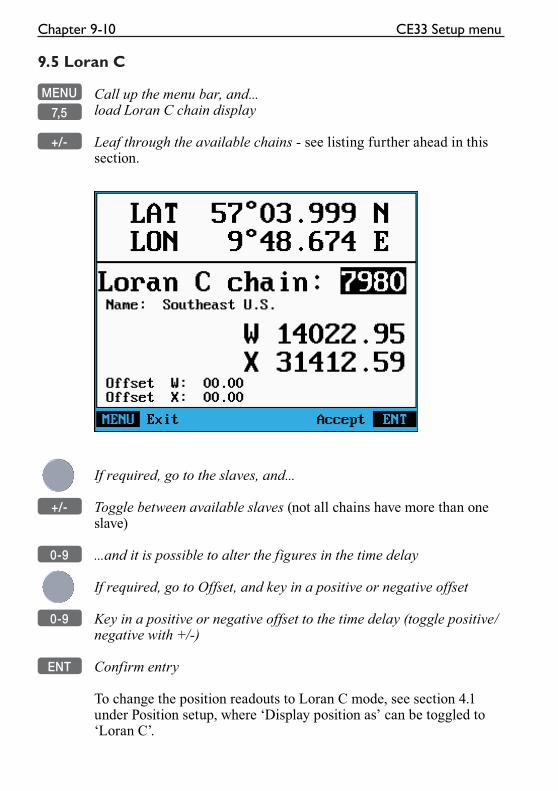
Chapter 9-10 CE33 Setup menu
9.5 Loran C
MENU Call up the menu bar, and...
7,5 load Loran C chain display
+/- Leaf through the available chains - see listing further ahead in this section.
If required, go to the slaves, and...
+/- Toggle between available slaves (not all chains have more than one slave)
0-9 ...and it is possible to alter the figures in the time delay
If required, go to Offset, and key in a positive or negative offset
0-9 Key in a positive or negative offset to the time delay (toggle positive/negative with +/-)
ENT Confirm entry
To change the position readouts to Loran C mode, see section 4.1 under Position setup, where ‘Display position as’ can be toggled to ‘Loran C’.
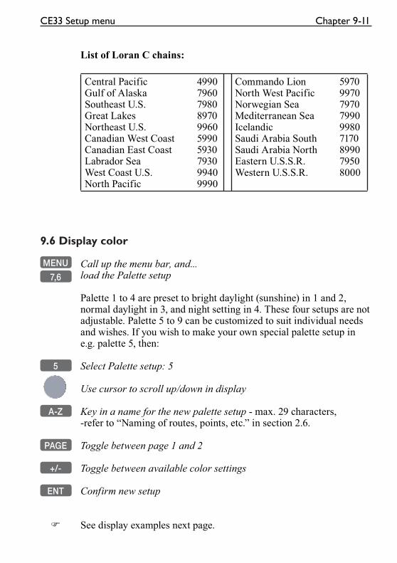
CE33 Setup menu Chapter 9-11
List of Loran C chains:
Central PacificGulf of AlaskaSoutheast U.S.Great LakesNortheast U.S.Canadian West CoastCanadian East CoastLabrador SeaWest Coast U.S.North Pacific
4990796079808970996059905930793099409990
Commando LionNorth West PacificNorwegian SeaMediterranean SeaIcelandicSaudi Arabia SouthSaudi Arabia NorthEastern U.S.S.R.Western U.S.S.R.
597099707970799099807170899079508000
9.6 Display color
MENU Call up the menu bar, and...
7,6 load the Palette setup
Palette 1 to 4 are preset to bright daylight (sunshine) in 1 and 2, normal daylight in 3, and night setting in 4. These four setups are not adjustable. Palette 5 to 9 can be customized to suit individual needs and wishes. If you wish to make your own special palette setup in e.g. palette 5, then:
5 Select Palette setup: 5
Use cursor to scroll up/down in display
A-Z Key in a name for the new palette setup - max. 29 characters,-refer to “Naming of routes, points, etc.” in section 2.6.
PAGE Toggle between page 1 and 2
+/- Toggle between available color settings
ENT Confirm new setup
� See display examples next page.
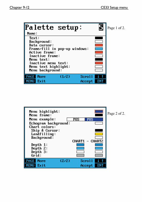
Chapter 9-12 CE33 Setup menu
Page 1 of 2.
Page 2 of 2.
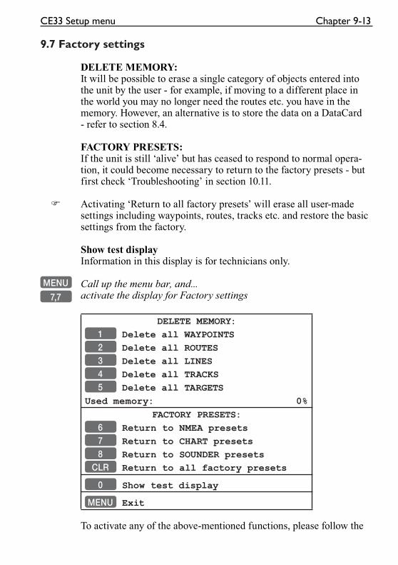
CE33 Setup menu Chapter 9-13
9.7 Factory settings
DELETE MEMORY:It will be possible to erase a single category of objects entered into the unit by the user - for example, if moving to a different place in the world you may no longer need the routes etc. you have in the memory. However, an alternative is to store the data on a DataCard - refer to section 8.4.
FACTORY PRESETS:If the unit is still ‘alive’ but has ceased to respond to normal opera-tion, it could become necessary to return to the factory presets - but first check ‘Troubleshooting’ in section 10.11.
� Activating ‘Return to all factory presets’ will erase all user-made settings including waypoints, routes, tracks etc. and restore the basic settings from the factory.
Show test displayInformation in this display is for technicians only.
MENU Call up the menu bar, and...
7,7 activate the display for Factory settings
DELETE MEMORY:
1 Delete all WAYPOINTS
2 Delete all ROUTES
3 Delete all LINES
4 Delete all TRACKS
5 Delete all TARGETS
Used memory: 0%
FACTORY PRESETS:
6 Return to NMEA presets
7 Return to CHART presets
8 Return to SOUNDER presets
CLR Return to all factory presets
0 Show test display
MENU Exit
To activate any of the above-mentioned functions, please follow the
Chapter 9-14 CE33 Setup menu
instructions in the display. However, any attempt to make any type of change, will first of all generate a WARNING display to inform you that you are about to erase some or all data/settings.
ENT If you are absolutely sure, press [ENT] to complete the job
MENU If not absolutely sure, press [MENU] to exit function without having made any changes
POWER OFF - RESETIn case, for some reason, the unit is totally locked i.e. no immediate response from the keypad, then first try to reset the unit by discon-necting the power supply. Reconnect the power cable and then start up the unit again by presssing and holding the [PWR] key until a picture appears on the screen.
MASTER RESET (will return all settings to factory presets)If the Power off - reset does not solve the problem, you may have to perform a master reset by disconnecting the power supply, and then while reconnecting the power cable you will have to press the [PWR] and [CLR] keys at the same time, and hold both keys depressed until a picture appears on the screen. All user-made data will be erased, and all settings are returned to factory presets.
CE33 Installation and service Chapter 10-1
10. Installation and service
10.1 Installation notes
For a number of reasons, all user-related decisions, setups, etc. should be noted in these two pages as they occur. This information may be helpful if your unit has been updated with new software, reset or in for service.
Transducer type:
Echosounder setup:
Transducer
Depth
Frequency
Keel depth
Other important settings:

Chapter 10-2 CE33 Installation and service
Other important settings (continued):
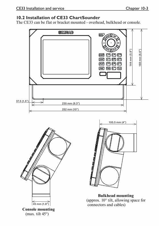
37.5 (1.5”)235 mm (9.3”)
252 mm (10”)
144
mm
(5.
8”)
168
mm
(6.
6”)
45 mm (1.8”)
100.5 mm (4”)
CE33 Installation and service Chapter 10-3
10.2 Installation of CE33 ChartSounderThe CE33 can be flat or bracket mounted - overhead, bulkhead or console.
Bulkhead mounting (approx. 10° tilt, allowing space for connectors and cables) Console mounting (max. tilt 45°)
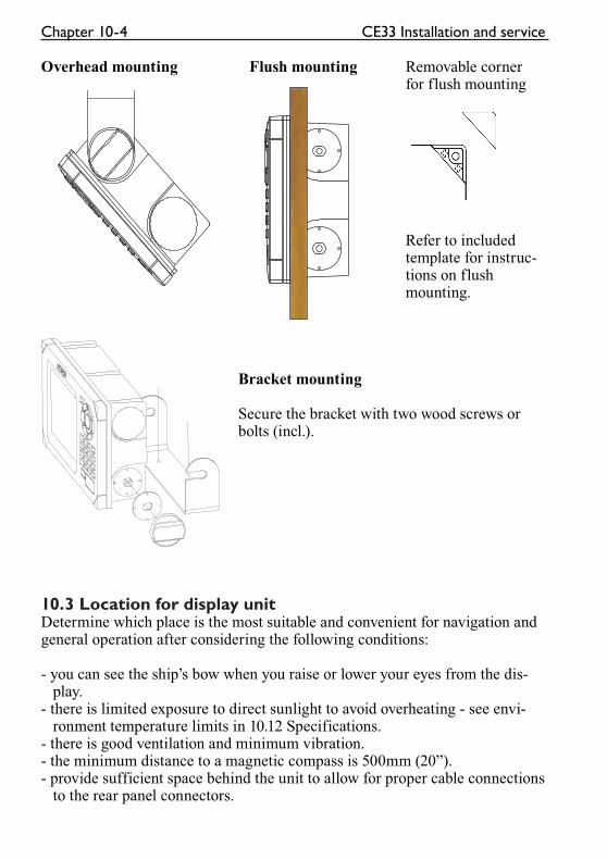
Chapter 10-4 CE33 Installation and service
Overhead mounting Flush mounting Removable corner for flush mounting
Refer to included template for instruc- tions on flush mounting.
Bracket mounting
Secure the bracket with two wood screws or bolts (incl.).
10.3 Location for display unitDetermine which place is the most suitable and convenient for navigation and general operation after considering the following conditions:
- you can see the ship’s bow when you raise or lower your eyes from the dis- play.- there is limited exposure to direct sunlight to avoid overheating - see envi- ronment temperature limits in 10.12 Specifications.- there is good ventilation and minimum vibration.- the minimum distance to a magnetic compass is 500mm (20”).- provide sufficient space behind the unit to allow for proper cable connections to the rear panel connectors.
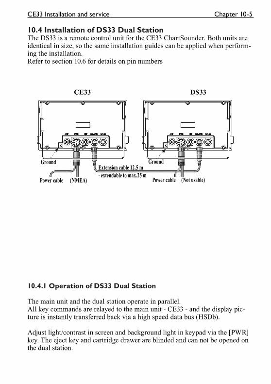
Ground Ground
Power cable (NMEA) Power cable (Not usable)
Extension cable 12.5 m
- extendable to max.25 m
CE33 Installation and service Chapter 10-5
10.4 Installation of DS33 Dual StationThe DS33 is a remote control unit for the CE33 ChartSounder. Both units are identical in size, so the same installation guides can be applied when perform-ing the installation. Refer to section 10.6 for details on pin numbers
CE33 DS33
10.4.1 Operation of DS33 Dual Station
The main unit and the dual station operate in parallel.All key commands are relayed to the main unit - CE33 - and the display pic-ture is instantly transferred back via a high speed data bus (HSDb).
Adjust light/contrast in screen and background light in keypad via the [PWR] key. The eject key and cartridge drawer are blinded and can not be opened on the dual station.
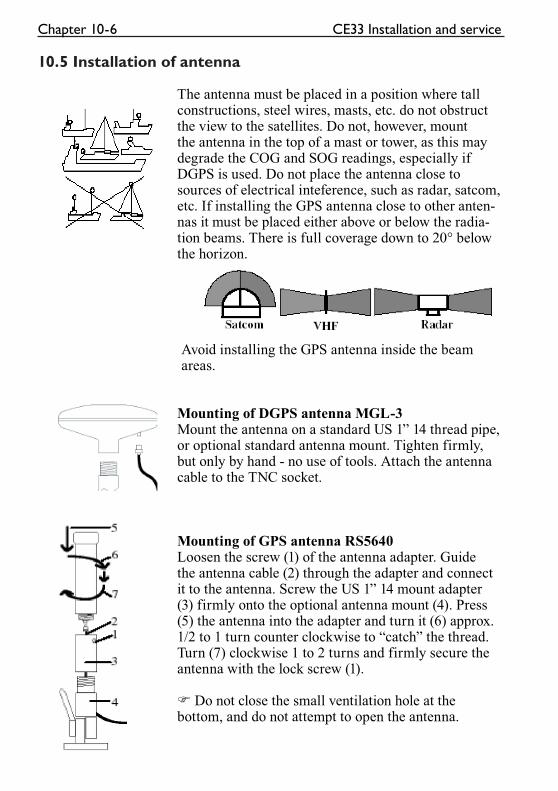
Chapter 10-6 CE33 Installation and service
10.5 Installation of antenna
The antenna must be placed in a position where tall constructions, steel wires, masts, etc. do not obstruct the view to the satellites. Do not, however, mount the antenna in the top of a mast or tower, as this may degrade the COG and SOG readings, especially if DGPS is used. Do not place the antenna close to sources of electrical inteference, such as radar, satcom, etc. If installing the GPS antenna close to other anten-nas it must be placed either above or below the radia-tion beams. There is full coverage down to 20° below the horizon.
Avoid installing the GPS antenna inside the beam areas.
Mounting of DGPS antenna MGL-3Mount the antenna on a standard US 1” 14 thread pipe, or optional standard antenna mount. Tighten firmly, but only by hand - no use of tools. Attach the antenna cable to the TNC socket.
Mounting of GPS antenna RS5640Loosen the screw (1) of the antenna adapter. Guide the antenna cable (2) through the adapter and connect it to the antenna. Screw the US 1” 14 mount adapter (3) firmly onto the optional antenna mount (4). Press (5) the antenna into the adapter and turn it (6) approx. 1/2 to 1 turn counter clockwise to “catch” the thread. Turn (7) clockwise 1 to 2 turns and firmly secure the antenna with the lock screw (1).
� Do not close the small ventilation hole at the bottom, and do not attempt to open the antenna.
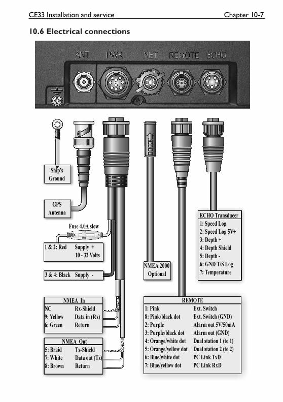
ECHO Transducer
1: Speed Log
2: Speed Log 5V+
3: Depth +
4: Depth Shield
5: Depth -
6: GND T/S Log
7: Temperature
REMOTE
1: Pink Ext. Switch
8: Pink/black dot Ext. Switch (GND)
2: Purple Alarm out 5V/50mA
3: Purple/black dot Alarm out (GND)
4: Orange/white dot Dual station 1 (to 1)
5: Orange/yellow dot Dual station 2 (to 2)
6: Blue/white dot PC Link TxD
7: Blue/yellow dot PC Link RxD
Ship’s
Ground
GPS
Antenna
1 & 2: Red Supply +
10 - 32 Volts
3 & 4: Black Supply -
NMEA In
NC Rx-Shield
9: Yellow Data in (Rx)
6: Green Return
NMEA Out
5: Braid Tx-Shield
7: White Data out (Tx)
8: Brown Return
NMEA 2000
Optional
Fuse 4.0A slow
CE33 Installation and service Chapter 10-7
10.6 Electrical connections
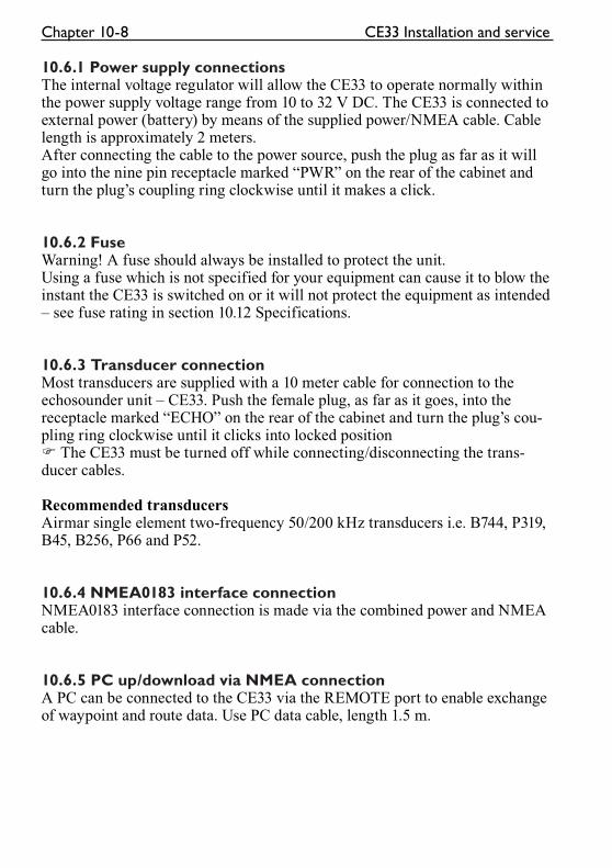
Chapter 10-8 CE33 Installation and service
10.6.1 Power supply connectionsThe internal voltage regulator will allow the CE33 to operate normally within the power supply voltage range from 10 to 32 V DC. The CE33 is connected to external power (battery) by means of the supplied power/NMEA cable. Cable length is approximately 2 meters.After connecting the cable to the power source, push the plug as far as it will go into the nine pin receptacle marked “PWR” on the rear of the cabinet and turn the plug’s coupling ring clockwise until it makes a click.
10.6.2 FuseWarning! A fuse should always be installed to protect the unit.Using a fuse which is not specified for your equipment can cause it to blow the instant the CE33 is switched on or it will not protect the equipment as intended – see fuse rating in section 10.12 Specifications.
10.6.3 Transducer connectionMost transducers are supplied with a 10 meter cable for connection to the echosounder unit – CE33. Push the female plug, as far as it goes, into the receptacle marked “ECHO” on the rear of the cabinet and turn the plug’s cou-pling ring clockwise until it clicks into locked position � The CE33 must be turned off while connecting/disconnecting the trans-ducer cables.
Recommended transducersAirmar single element two-frequency 50/200 kHz transducers i.e. B744, P319, B45, B256, P66 and P52.
10.6.4 NMEA0183 interface connectionNMEA0183 interface connection is made via the combined power and NMEA cable.
10.6.5 PC up/download via NMEA connectionA PC can be connected to the CE33 via the REMOTE port to enable exchange of waypoint and route data. Use PC data cable, length 1.5 m.
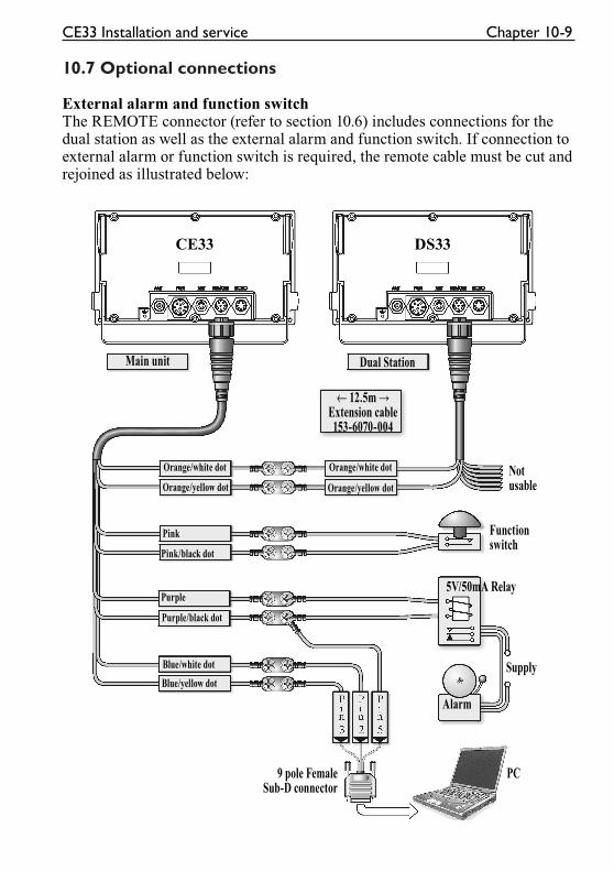
Main unit Dual Station
← 12.5m →Extension cable153-6070-004
Orange/white dot
Orange/yellow dot
Purple
Blue/white dot
Pink/black dot
Purple/black dot
Blue/yellow dot
Notusable
Functionswitch
5V/50mA Relay
Supply
Alarm
PC9 pole FemaleSub-D connector
Orange/white dot
Pink
Orange/yellow dot
CE33 Installation and service Chapter 10-9
10.7 Optional connections
External alarm and function switchThe REMOTE connector (refer to section 10.6) includes connections for the dual station as well as the external alarm and function switch. If connection to external alarm or function switch is required, the remote cable must be cut and rejoined as illustrated below:
CE33 DS33
Chapter 10-10 CE33 Installation and service
Overview of various optional connections:
-Dual Station DS33
-Performance Instruments
-Color Trackplotter
-Differential Beacon Receiver
-Water speed and temperature sensor
-Autopilot
-Radar
-Yeoman digitizer
-NMEA Buffer RS5345
-PC - WPs & routes up/download
-Other equipment via NMEA0183, 0182, 0180
10.8 Basic transducer and cable informationThe installation should be carefully planned in advance, keeping in mind the standard cable length of 10 meters (32 feet) which is connected to the trans-ducer. In the event where the standard cable is not long enough, up to an addi-tional 10 meters (32 feet) may be connected without a noticeable reduction of the performance. The cable must be of the same type as the standard cable.� The CE33 must be turned off while connecting/disconnecting the trans-ducer cable.
The use of longer cable runs, while possible, always increases the likelihood of increased interference and decreased performance. Care must be taken when increasing the cable lengths to ensure that proper, adequate and consistent shielding is maintained, that cable of adequate cross section is used, and that all connections are properly made and protected from the effects of the marine environment.
If possible, running the transducer cable through a grounded conduit will greatly decrease the likelihood of interference. Likewise, the transducer cable should be run as far as possible from other electrical cabling. If it is absolutely necessary to pass close to other cabling, it is best to keep as much distance as possible, and to make all crossings as close to a right angle as possible.
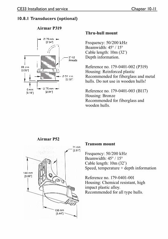
CE33 Installation and service Chapter 10-11
10.8.1 Transducers (optional)
Airmar P319Thru-hull mount
Frequency: 50/200 kHzBeamwidth: 45° / 15°Cable length: 10m (32’)Depth information.
Reference no. 179-0401-002 (P319)Housing: Reinforced plasticRecommended for fiberglass and metal hulls. Do not use in wooden hulls!
Reference no. 179-0401-003 (B117)Housing: BronzeRecommended for fiberglass and wooden hulls.
Airmar P52Transom mount
Frequency: 50/200 kHzBeamwidth: 45° / 15°Cable length: 10m (32’)Speed, temperature + depth information
Reference no. 179-0401-001Housing: Chemical resistant, high impact plastic alloy.Recommended for all type hulls.
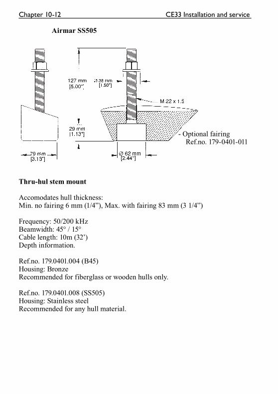
Chapter 10-12 CE33 Installation and service
Airmar SS505
- Optional fairing Ref.no. 179-0401-011
Thru-hul stem mount
Accomodates hull thickness: Min. no fairing 6 mm (1/4”), Max. with fairing 83 mm (3 1/4”)
Frequency: 50/200 kHzBeamwidth: 45° / 15°Cable length: 10m (32’)Depth information.
Ref.no. 179.0401.004 (B45)Housing: BronzeRecommended for fiberglass or wooden hulls only.
Ref.no. 179.0401.008 (SS505)Housing: Stainless steelRecommended for any hull material.
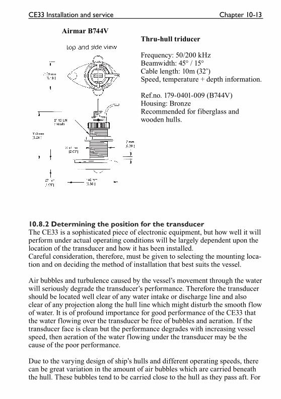
CE33 Installation and service Chapter 10-13
Airmar B744VThru-hull triducer
Frequency: 50/200 kHzBeamwidth: 45° / 15°Cable length: 10m (32’)Speed, temperature + depth information.
Ref.no. 179-0401-009 (B744V)Housing: BronzeRecommended for fiberglass and wooden hulls.
10.8.2 Determining the position for the transducerThe CE33 is a sophisticated piece of electronic equipment, but how well it will perform under actual operating conditions will be largely dependent upon the location of the transducer and how it has been installed. Careful consideration, therefore, must be given to selecting the mounting loca-tion and on deciding the method of installation that best suits the vessel.
Air bubbles and turbulence caused by the vessel’s movement through the water will seriously degrade the transducer’s performance. Therefore the transducer should be located well clear of any water intake or discharge line and also clear of any projection along the hull line which might disturb the smooth flow of water. It is of profound importance for good performance of the CE33 that the water flowing over the transducer be free of bubbles and aeration. If the transducer face is clean but the performance degrades with increasing vessel speed, then aeration of the water flowing under the transducer may be the cause of the poor performance.
Due to the varying design of ship’s hulls and different operating speeds, there can be great variation in the amount of air bubbles which are carried beneath the hull. These bubbles tend to be carried close to the hull as they pass aft. For
Chapter 10-14 CE33 Installation and service
this reason, it is desirable for the transducer to be mounted on a fairing block which holds the transducer away from the hull and which directs the flow of aerated water around the sides of the transducer rather than over the face of the transducer.
On deep keeled vessels, care must be taken to ensure that the transducer beam will not be blocked by any part of the keel. Although the appropriate mount-ing location that meets all requirements depends on the type of vessel and its normal operating speeds, a practical choice is usually somewhere between one third and one half of the vessel’s water line length from the bow. Leveling blocks may be designed accordingly to meet this requirement.
� The more the transducer protrudes from the hull, the better the results will be.
Particularly at lower frequency operation (50kHz), interference from propel-ler noise can be a significant problem. This can be seen as an increase in the “noise” on the echosounder display when the propeller speed is increased. To help reduce this, the transducer’s mounting face may be angled slightly for-ward on the order of 3-5°. The goal is to incline the transducer so that a line of sight along the transducer’s radiating surface passes below the propeller.
� Keeping the propeller clean and free of any nicks or roughness will assist in minimizing interference from propeller noise due to cavitation.
Sources of noise to consider:
Water/air noise
Acoustic noise Electrical noise
Air bubblesTurbulencePropeller
Main engine
Reduction gear propeller
shaft
Generators auxiliary
engines
Power plant for freezers
Hydraulic pumps
Rudder engine
Bow thruster
Stern thruster
Noise from electrical cables
Noise from generators
Poor grounding of instrument
Radiated noise from other
instruments
Dc – Dc converters
Electrical winches
Neon lights
etc.
CE33 Installation and service Chapter 10-15
10.9 Preventive maintenance
Surface cleaning – to keep the CE33 cabinet and display screen clean, wipe the surfaces with a clean damp cloth. For heavier cleaning, use a clean, damp cloth which has been dipped in a solution of a mild dish detergent and water. Wring out firmly before wiping the unit.� Never use cleaning solutions containing spirit or alcohol.
Electrical connections – periodically check the electrical connections. Make sure that connections are tight and that no cables are frayed or worn.
10.10 Repair and serviceThe CE33 is sealed and does not contain any user serviceable parts. Opening of this unit will void its warranty. If the CE33 requires servicing or repair, call your authorized SIMRAD dealer, but first check section 10.11 below.
Spare parts – fuses may be bought from a chandler or a marine supply store. Use only fuses specified for this unit – see 10.12 Specifications.If you require a SIMRAD part, please contact your authorized dealer.
10.11 Troubleshooting
For all fault finding, first check that the supply voltage is between 10-32 VDC
Symptom Check Remedy
No picture on display
screen
Check that the unit is
turned on
Press the [PWR] key on
keypad
Check fuse in power cable
fuse holder
Replace fuse. Use only
type 4.0A slow
Picture appears on the
display screen, but image
is too dark or too bright
Press [PWR], adjust light/
contrast, press [ENT]
No normal picture or key
operation
Turn unit off and on again
Disconnect power and
connect power again
Check via [MENU], [1],
[3] if C-MAP chart is
defective
Remove C-MAP chart if
defective
Return to factory presets,
see section 9.7
Chapter 10-16 CE33 Installation and service
Symptom Check Remedy
No GPS position update Check external position to
be OFF, refer to interface
display in [MENU],[7],[2]
Check antenna and cable Replace antenna or cable
Screen update is
extremely slow
Check that the stored
Tracks and Routes (not
currently in use) are not
all drawn up on the chart
Turn off ‘Course line’
for each stored route in
sec.5.2, and turn off ‘Dis-
play track’ in sec.5.6
Echo picture appears
normal, but no target are
shown or only random
“noise” is seen
Check that the correct
transducer frequency is
selected
Go to Echosounder setup
and select transducer fre-
quency in section 7.8
Check that the transducer
connectors are securely
mated with the unit
Correctly mate the con-
nectors to the unit
Check that the receiver
gain is set high enough
Increase the receiver gain
in 7.9 Presentation setup
Check that the range is
correct for the water depth
Adjust the range in 7.9
Presentation setup
Excessive noise in echo
picture
Check for correct ground-
ing
Connected equip-
ment must be properly
grounded to the main unit
All data is deleted after
turning off the unit and
turning it back on
Check battery lifetime.
Expected lifetime is min.
5 years
Internal battery must be
replaced by authorized
dealer
10.12 Specifications
General dataPower supply: 12 and 24 V DC (10-32 V DC max) 8-16 wattPower cable: Power/NMEA cable, 2 m (153-6070-002)Dimensions: H:144 mm (5.8”) W:252 mm (10”) D:70 mm (2.8”)Weight: 1.5 kg (3.0 lbs)Environment: -10 to +50°C, IEC 60945, waterproof USC 46 CFR and IP55Housing: Casted aluminum back, polycarbonate frontDisplay: TFT color, power backlight: 5.7” 320x240 pixels, or ..... STN transflective monochrome 6” 320x340 pixelsPresentation: 4 pages. Manual, dedicated and remote switch, and automatic sequencing.
CE33 Installation and service Chapter 10-17
Interfacing: 1 port in/out NMEA 0183/0182/0180 PC up/download WPL and RTE 1 port NMEA 2000 (optional) Alarm - signal output 5 V 50 mAFuse: 4.0A slow
GPS sectionReceiver type: 14 channel parallel, C/A code, 8 state Kalman filterAccuracy: Position (DGPS): 2-5 m RMS Position (SDGPS): 3-7 m RMS Position (GPS): 8 m RMS Speed: 0.1 kn Course: 1°Speed filter: 10 settingsUpdate rate: 1 second interval, typicalDynamics: Velocity: 600 km/h Acceleration: 10 m / s2
GPS antenna RS5640 DGPS antenna MGL-3Type: Quadrifilar Helix Patch and H-field Dimensions: L:230 mm H:75 mm D:38 mm D:127 mmWeight: 150 g 600 g
Environment: -35°C to +75°C, 95% rel.Mounting: 1” 14 thread (standard US)Cable: 10 m RG58 (standard), 15 m RG58 (option), max. 30 m RG213
Chartplotter sectionChart system: C-MAP NT+Presentation: Semi dual chart - two charts in individual scales and detail levelsInternal memory: Dynamic storage with combinations of/or totals up to: 35,000 marks/waypoints 10,000 waypoints with name (25 characters) 50,000 trackpoints 50,000 line sections 1,000 routes
Chapter 10-18 CE33 Installation and service
Echosounder sectionFrequencies: 50 or 200 kHz, selectableTransmit power:600 watt RMS (4,800 W PP)Impedance: 175 / 425 ohmsDisplay ranges: 5 to 1000 m in 21 steps, manual and auto modeDetection ranges: Frequency Beam Bottom 50 kHz 45° 800 m / 2,400 ft 200 kHz 15° 350 m / 1,050 ftPulse length: Short, medium, long and autoTransmissionrate: 10 pings per secondAlarms: Fish, max. and min. depthZoom mode: Bottom and VRM expansion, 6 to 50 meters, feet or fathomsEvent marker: At current ping and depth memoryPicture speed: True distance or time, high, medium, low, and freezeNoise filter: User selectable on/offEcho presentation: A-scope and white line discriminationTemperature: Sensor or NMEASpeed: Sensor or NMEA
Alternative 50/200 kHz medium-rang transducers (Airmar Des.A)B256: 1kW medium range transducer, 16x28° and 4x6° beams.B45: 600W bronze stem mount transducer, 45° and 15° beam.B744V: 600W bronze thru hull triducer, depth, speed and temperature, 45° and 15° beam.P52: 600W plastic transom mount triducer, depth, speed and temperature, 45° and 15° beam.P319: 600W plastic thru-hull transducer, 45° and 15° beam.ST650: Speed and temperature only.
OptionsSimrad DataCardsC-MAP NT+ electronic charts6-channel NMEA Buffer RS5345PC data cable, 1.5 m (153-6070-006)Antenna cable 15 m RG58DS33 Dual Station, 5.7” TFT LCD color screen or 6” monochrome, incl. 12.5 m cable (153-6070-004) - max. length 25 m.Sunhood
CE33 Glossary of terms Appendix A-1
Almanac – a satellite’s almanac data, is data which determines an approxi-mate lane for satellites in orbit. The almanac data is used by the GPS receiver to find and lock onto the satellite signal. CE33 has a built-in basic almanac.
Auto trackpoint shift – will automatically shift to the next trackpoint in the track and provide new steering details (Track navigation).
Auto waypoint shift – will automatically shift to the next waypoint in the route and provide new steering details (Route navigation).
AVN – Approximate Velocity Necessary – to arrive at a specific waypoint at a specific time.
Bearing – is the direction of where to go e.g. towards a specific waypoint.
Course – Course Over Ground, magnetic or true. The direction of which the vessel is moving.
Configuration – the configuration functions of the CE33 allow you to adapt the system more specifically to your needs. You may set Units of measure (feet, fathoms, meters, etc.), Menu languages, Scroll speed, etc.
dGPS – differential data is received from built-in DGPS module or an exter-nal DGPS Receiver.
ETA - Estimated Time of Arrival - at a specific waypoint if keeping a steady speed.
Great circle – the shortest distance between two points on the globe.
Grid - on chart can be set to AUTO / ON / OFF. ON = the grid is always visible on the chart display.OFF = the grid is turned off and will not show on the chart display.AUTO = the grid will not appear in the ordinary chart display, but will be there when in overzoom and when “Chart” is turned off in the Chart setup, which means that there will be no World chart presented and no C-MAP charts presented – only user-made data such as waypoints, routes, lines and tracks, etc.
Heading – the direction of which the vessel is pointing (from ext.compass).
LOG speed calibration – the unit is preset to receive 19000 pulses per nauti-cal mile from the log transducer (paddle wheel). However the figure might have to be changed to compensate for various transducers and actual water
Appendix A-2 CE33 Glossary of terms
flow passing the transducer. The correct pulse rate is calculated by: 19000 x indicated speed (e.g. 4kn) = 15.200 pulses/nm actual speed (GPS) (e.g. 5kn)
Measurement units – the user may select the displayed units to be one of the following: m meters ft feet fm fathomsnm nautical mile, 1 nm is 1,852 meterskn knots, nautical mile per hourkm kilometer, 1 km is 1,000 meterskh kilometer per hourmi statute mile, 1 mile is 1,609 metersmh mile per hour
MENU – the selection of main menus will be shown in the upper part of the screen. Leaf through the menus by means of the cursor key and the [ENT] key, or use the numerical keys to activate one of the menus.
Navigation simulator - the chartplotter function features a built-in navigation simulator which can be used for demonstration purpose or for practicing ‘live’ navigation in ‘off season’.Navigation to cursor or waypoint, in route or in track is started as described in chapter 6. The navigation simulator is started via the NMEA interface setup: Press [MENU],[7],[2], [PAGE]; go to ‘OFF’ next to ‘External pos data:’ and press the [-] key to toggle to: Dead reck.; move cursor to the right and enter a speed value of e.g. 10 knots; press [ENT] twice.The ship symbol will now ‘sail’ to the point of destination directly or via the route you have selected and you can see how the alarms and automatic way-point shift all work, as if you were sailing yourself. You can also simulate making a track trailing the ship or plotting eventmarks, etc. as the ship is ‘sail-ing’.
NMEA – National Marine Electronics Association. The NMEA is an organi-zation of manufacturers of marine electronics equipment. They have adopted the NMEA0183 as a standard for communications between various types of marine electronic equipment.
Port side – left (red).
Restart to approaching point – will automatic recalculate the navigation data from current position to approaching point.
CE33 Glossary of terms Appendix A-3
Rhumbline – is the straight line to a waypoint on a chart.
Route name – each route can be given a name for easy identification.
SDGPS - Satellite Differential Global Positioning System - will provide posi-tion corrections from received satellite signals.
Speed – Speed Over Ground, measured in knots, kilometers, and miles.
Starboard side – right (green).
TFT – Thin-Film Transistor (Active matrix) display.
UTC – Universal Time Coordinates, which is equal to standard time in London (GMT). UTC is not affected by the local summertime adjustments.
Velocity – speed towards approaching waypoint.
Waypoint name – a name can be added to each waypoint for easy identifica-tion.
WPplot – instant storage of actual position as a waypoint.
XTE – Cross-Track-Error (-Distance), measured magnitude of the position error perpendicular to the intended track line.
Echosounder section:
Alarms – can be set to sound a “beep” if the echosounder detects a target above (shallower than) a minimum alarm depth or below (deeper than) a maxi-mum alarm depth. The CE33 allows you to set the alarm depths and to enable or disable both the minimum and maximum depth alarms.
A-scope – a method of displaying the echosounder information. In A-Scope mode, the echoes are displayed in a “bar-graph” format, with stronger echoes displayed not only in the color representing their target strength, but also in a width representing their target strength.
Color threshold – the color threshold function allows the “weaker” targets and noise which may be shown on the display screen to be eliminated from the display. These targets are usually shown in the weaker target colors such as blues and greens. The Color threshold allows you to choose not to display the blues, or the blues and greens, etc. Doing this will leave only the stronger
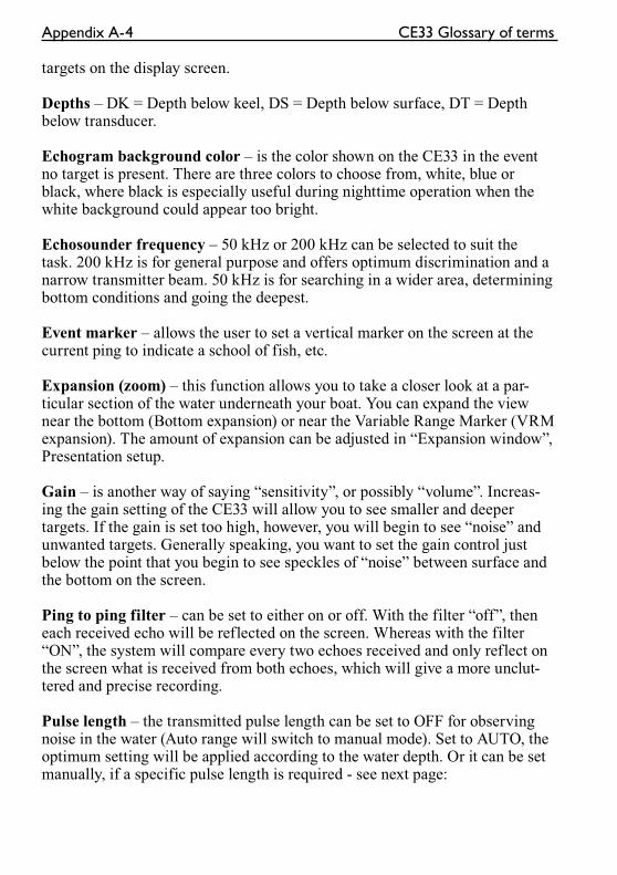
Appendix A-4 CE33 Glossary of terms
targets on the display screen.
Depths – DK = Depth below keel, DS = Depth below surface, DT = Depth below transducer.
Echogram background color – is the color shown on the CE33 in the event no target is present. There are three colors to choose from, white, blue or black, where black is especially useful during nighttime operation when the white background could appear too bright.
Echosounder frequency – 50 kHz or 200 kHz can be selected to suit the task. 200 kHz is for general purpose and offers optimum discrimination and a narrow transmitter beam. 50 kHz is for searching in a wider area, determining bottom conditions and going the deepest.
Event marker – allows the user to set a vertical marker on the screen at the current ping to indicate a school of fish, etc.
Expansion (zoom) – this function allows you to take a closer look at a par-ticular section of the water underneath your boat. You can expand the view near the bottom (Bottom expansion) or near the Variable Range Marker (VRM expansion). The amount of expansion can be adjusted in “Expansion window”, Presentation setup.
Gain – is another way of saying “sensitivity”, or possibly “volume”. Increas-ing the gain setting of the CE33 will allow you to see smaller and deeper targets. If the gain is set too high, however, you will begin to see “noise” and unwanted targets. Generally speaking, you want to set the gain control just below the point that you begin to see speckles of “noise” between surface and the bottom on the screen.
Ping to ping filter – can be set to either on or off. With the filter “off”, then each received echo will be reflected on the screen. Whereas with the filter “ON”, the system will compare every two echoes received and only reflect on the screen what is received from both echoes, which will give a more unclut-tered and precise recording.
Pulse length – the transmitted pulse length can be set to OFF for observing noise in the water (Auto range will switch to manual mode). Set to AUTO, the optimum setting will be applied according to the water depth. Or it can be set manually, if a specific pulse length is required - see next page:
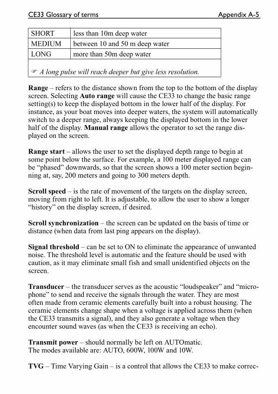
CE33 Glossary of terms Appendix A-5
SHORT less than 10m deep water
MEDIUM between 10 and 50 m deep water
LONG more than 50m deep water
� A long pulse will reach deeper but give less resolution.
Range – refers to the distance shown from the top to the bottom of the display screen. Selecting Auto range will cause the CE33 to change the basic range setting(s) to keep the displayed bottom in the lower half of the display. For instance, as your boat moves into deeper waters, the system will automatically switch to a deeper range, always keeping the displayed bottom in the lower half of the display. Manual range allows the operator to set the range dis-played on the screen.
Range start – allows the user to set the displayed depth range to begin at some point below the surface. For example, a 100 meter displayed range can be “phased” downwards, so that the screen shows a 100 meter section begin-ning at, say, 200 meters and going to 300 meters depth.
Scroll speed – is the rate of movement of the targets on the display screen, moving from right to left. It is adjustable, to allow the user to show a longer “history” on the display screen, if desired.
Scroll synchronization – the screen can be updated on the basis of time or distance (when data from last ping appears on the display).
Signal threshold – can be set to ON to eliminate the appearance of unwanted noise. The threshold level is automatic and the feature should be used with caution, as it may eliminate small fish and small unidentified objects on the screen.
Transducer – the transducer serves as the acoustic “loudspeaker” and “micro-phone” to send and receive the signals through the water. They are most often made from ceramic elements carefully built into a robust housing. The ceramic elements change shape when a voltage is applied across them (when the CE33 transmits a signal), and they also generate a voltage when they encounter sound waves (as when the CE33 is receiving an echo).
Transmit power – should normally be left on AUTOmatic. The modes available are: AUTO, 600W, 100W and 10W.
TVG – Time Varying Gain – is a control that allows the CE33 to make correc-
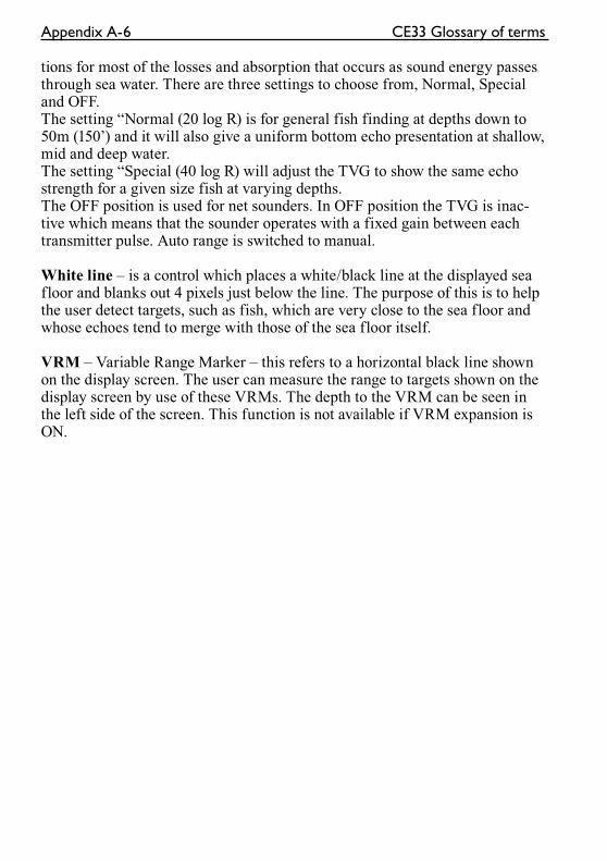
Appendix A-6 CE33 Glossary of terms
tions for most of the losses and absorption that occurs as sound energy passes through sea water. There are three settings to choose from, Normal, Special and OFF. The setting “Normal (20 log R) is for general fish finding at depths down to 50m (150’) and it will also give a uniform bottom echo presentation at shallow, mid and deep water. The setting “Special (40 log R) will adjust the TVG to show the same echo strength for a given size fish at varying depths.The OFF position is used for net sounders. In OFF position the TVG is inac-tive which means that the sounder operates with a fixed gain between each transmitter pulse. Auto range is switched to manual.
White line – is a control which places a white/black line at the displayed sea floor and blanks out 4 pixels just below the line. The purpose of this is to help the user detect targets, such as fish, which are very close to the sea floor and whose echoes tend to merge with those of the sea floor itself.
VRM – Variable Range Marker – this refers to a horizontal black line shown on the display screen. The user can measure the range to targets shown on the display screen by use of these VRMs. The depth to the VRM can be seen in the left side of the screen. This function is not available if VRM expansion is ON.
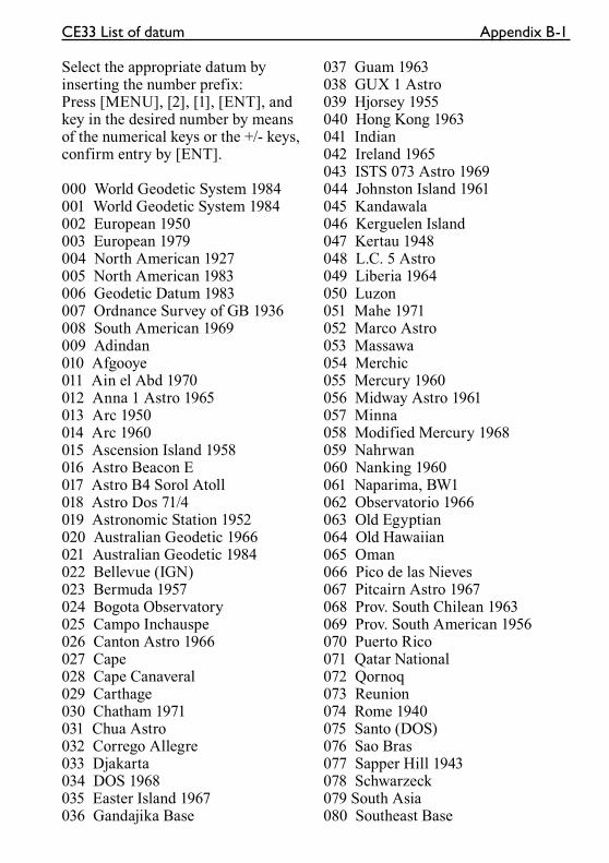
CE33 List of datum Appendix B-1
Select the appropriate datum by inserting the number prefix: Press [MENU], [2], [1], [ENT], and key in the desired number by means of the numerical keys or the +/- keys, confirm entry by [ENT].
000 World Geodetic System 1984001 World Geodetic System 1984002 European 1950003 European 1979004 North American 1927005 North American 1983006 Geodetic Datum 1983007 Ordnance Survey of GB 1936008 South American 1969009 Adindan010 Afgooye011 Ain el Abd 1970012 Anna 1 Astro 1965013 Arc 1950014 Arc 1960015 Ascension Island 1958016 Astro Beacon E017 Astro B4 Sorol Atoll018 Astro Dos 71/4019 Astronomic Station 1952020 Australian Geodetic 1966021 Australian Geodetic 1984022 Bellevue (IGN)023 Bermuda 1957024 Bogota Observatory025 Campo Inchauspe026 Canton Astro 1966027 Cape028 Cape Canaveral029 Carthage030 Chatham 1971031 Chua Astro032 Corrego Allegre033 Djakarta034 DOS 1968035 Easter Island 1967036 Gandajika Base
037 Guam 1963038 GUX 1 Astro039 Hjorsey 1955040 Hong Kong 1963041 Indian042 Ireland 1965043 ISTS 073 Astro 1969044 Johnston Island 1961045 Kandawala046 Kerguelen Island047 Kertau 1948048 L.C. 5 Astro049 Liberia 1964050 Luzon051 Mahe 1971052 Marco Astro053 Massawa054 Merchic055 Mercury 1960056 Midway Astro 1961057 Minna058 Modified Mercury 1968059 Nahrwan060 Nanking 1960061 Naparima, BW1062 Observatorio 1966063 Old Egyptian064 Old Hawaiian065 Oman066 Pico de las Nieves067 Pitcairn Astro 1967068 Prov. South Chilean 1963069 Prov. South American 1956070 Puerto Rico071 Qatar National072 Qornoq073 Reunion074 Rome 1940075 Santo (DOS)076 Sao Bras077 Sapper Hill 1943078 Schwarzeck079 South Asia080 Southeast Base
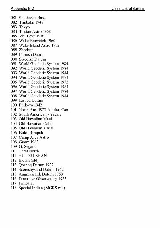
Appendix B-2 CE33 List of datum
081 Southwest Base082 Timbalai 1948083 Tokyo084 Tristan Astro 1968085 Viti Levu 1916086 Wake-Eniwetok 1960087 Wake Island Astro 1952088 Zanderij089 Finnish Datum090 Swedish Datum091 World Geodetic System 1984092 World Geodetic System 1984093 World Geodetic System 1984094 World Geodetic System 1984095 World Geodetic System 1972096 World Geodetic System 1984097 World Geodetic System 1984098 World Geodetic System 1984099 Lisboa Datum100 Pulkovo 1942101 North Am. 1927 Alaska, Can.102 South American - Yacare103 Old Hawaiian Maui104 Old Hawaiian Oahu105 Old Hawaiian Kauai106 Bukit Rimpah107 Camp Area Astro108 Guam 1963109 G. Segara110 Herat North111 HU-TZU-SHAN112 Indian (old)113 Qornoq Datum 1927114 Scoresbysund Datum 1952115 Angmassalik Datum 1958116 Tanarieve Observatory 1925117 Timbalai118 Special Indian (MGRS rel.)
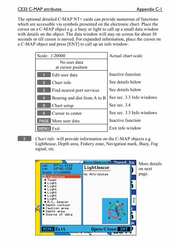
CE33 C-MAP attributes Appendix C-1
The optional detailed C-MAP NT+ cards can provide numerous of functions which are accessible via symbols presented on the electronic chart. Place the cursor on a C-MAP object e.g. a buoy or light to call up a small data window with details on the object. The data window will stay on screen for about 10 seconds or till cursor is moved. For expanded information, place the cursor on a C-MAP object and press [ENT] to call up an info window:
Scale: 1:20000 Actual chart scale
No user dataat cursor position
1 Edit user data Inactive function
2 Chart info See details below
3 Find nearest port services See details below
4 Bearing and dist from A to B See sec. 3.3 Info windows
9 Chart setup See sec. 3.4
0 Cursor to center See sec. 3.3 Info windows
PAGE More user data Inactive function
MENU Exit Exit info window
2 Chart info will provide information on the C-MAP objects e.g. Lighthouse, Depth area, Fishery zone, Navigation mark, Buoy, Fog signal, etc.
More details on next page.
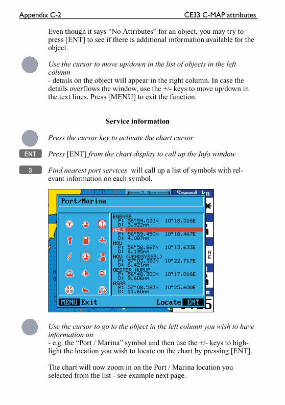
Appendix C-2 CE33 C-MAP attributes
Even though it says “No Attributes” for an object, you may try to press [ENT] to see if there is additional information available for the object.
Use the cursor to move up/down in the list of objects in the left column- details on the object will appear in the right column. In case the details overflows the window, use the +/- keys to move up/down in the text lines. Press [MENU] to exit the function.
Service information
Press the cursor key to activate the chart cursor
ENT Press [ENT] from the chart display to call up the Info window
3 Find nearest port services will call up a list of symbols with rel-evant information on each symbol.
Use the cursor to go to the object in the left column you wish to have information on- e.g. the “Port / Marina” symbol and then use the +/- keys to high-light the location you wish to locate on the chart by pressing [ENT].
The chart will now zoom in on the Port / Marina location you selected from the list - see example next page.
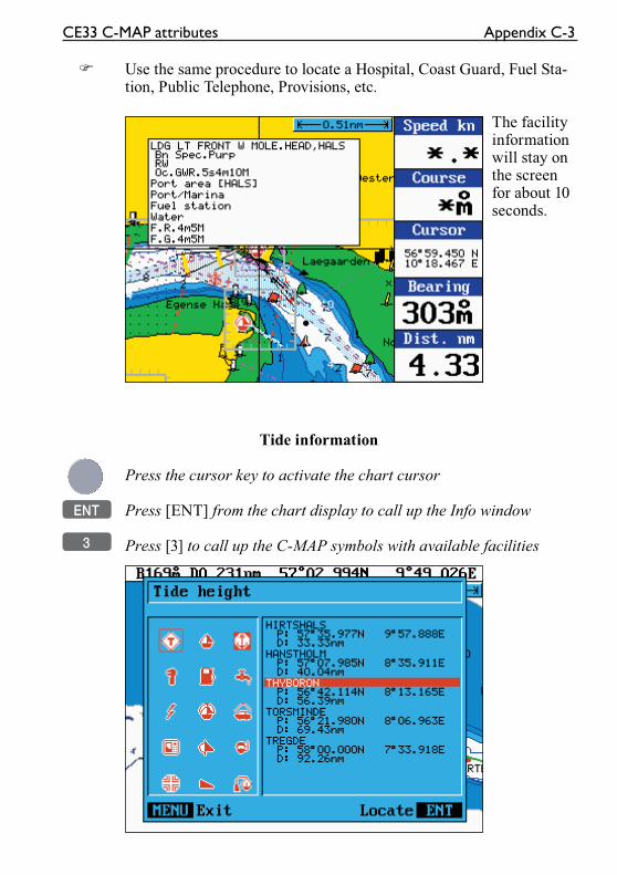
CE33 C-MAP attributes Appendix C-3
� Use the same procedure to locate a Hospital, Coast Guard, Fuel Sta-tion, Public Telephone, Provisions, etc.
The facility information will stay on the screen for about 10 seconds.
Tide information
Press the cursor key to activate the chart cursor
ENT Press [ENT] from the chart display to call up the Info window
3 Press [3] to call up the C-MAP symbols with available facilities
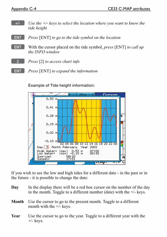
Appendix C-4 CE33 C-MAP attributes
+/- Use the +/- keys to select the location where you want to know the tide height
ENT Press [ENT] to go to the tide symbol on the location
ENT With the cursor placed on the tide symbol, press [ENT] to call up the INFO window
2 Press [2] to access chart info
ENT Press [ENT] to expand the information
Example of Tide height information:
If you wish to see the low and high tides for a different date - in the past or in the future - it is possible to change the date:
Day In the display there will be a red box cursor on the number of the day in the month. Toggle to a different number (date) with the +/- keys.
Month Use the cursor to go to the present month. Toggle to a different month with the +/- keys.
Year Use the cursor to go to the year. Toggle to a different year with the +/- keys.
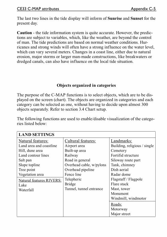
CE33 C-MAP attributes Appendix C-5
The last two lines in the tide display will inform of Sunrise and Sunset for the present day.
Caution - the tide information system is quite accurate. However, the predic-tions are subject to variables, which, like the weather, are beyond the control of man. The tide predictions are based on normal weather conditions. Hur-ricanes and strong winds will often have a strong influence on the water level, which can vary several meters. Changes in a coast line, either due to natural erosion, major storms or larger man-made constructions, like breakwaters or dredged canals, can also have influence on the local tide situation.
Objects organized in categories
The purpose of the C-MAP functions is to select objects, which are to be dis-played on the screen (chart). The objects are organized in categories and each category can be selected as one, without having to decide upon almost 300 objects separately. Refer to section 3.4 Chart setup.
The following functions are used to enable/disable visualization of the catego-ries listed below:
LAND SETTINGS
Natural features:Land area and coastline
Hill, dune area
Land contour lines
Salt pan
Slope topline
Tree point
Vegetation area
Cultural features:Airport area
Built-up area
Railway
Road in general
Overhead cable, w/pylons
Overhead pipeline
Fence line
Telepheric
Bridge
Tunnel, tunnel entrance
Landmarks:Building, religious / single
Cemetery
Fortifid structure
Siloway route part
Tank, chimney
Dish aerial
Radar dome
Flagstaff / Flagpole
Flare stack
Mast, tower
Monument
Windmill, windmotor
Natural features RIVERS:
Lake
Waterfall
Roads:
Motorway
Major street
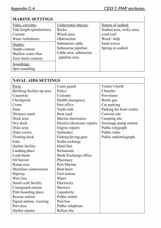
Appendix C-6 CE33 C-MAP attributes
MARINE SETTINGS
Tides, currents:
Tide height (predictions)
Current
Water turbulence
Underwater objects:
Rocks
Wreck area
Obstruction
Submarine cable
Submarine pipeline
Cable area, submarine
pipeline area
Nature of seabed:
Seabed area, rocky area,
coral reef
Weed / kelp
Sand waves
Spring in seabedDepths:
Depth contour
Shallow water blue
Zero meter contour
Soundings:
Spot sounding
NAVAL AIDS SETTINGS
Ports:
Berthing facility-up area
Causeway
Checkpoint
Crane
Dam
Distance mark
Dock area
Dry dock
Dyke area
Dyke crown
Floating dock
Gate
Harbor facility
Landing place
Lock basin
Oil barrier
Ramp area
Shoreline construction
Slipway
Weir line
Small craft facility
Coastguard station
Pilot boarding place
Rescue station
Signal station, warning
Port area
Harbor master
Coast guard
Police
Customs
Health emergency
Post office
Yacht club
Boat yard
Marine electronics
Electric/electronic repairs
Engine repairs
Sailmaker
Fishing/diving gear
Scuba recharge
Hotel/Inn
Restaurant
Bank/Exchange office
Pharmacy
Port/Marina
Boat hoist
Fuel station
Water
Electricity
Showers
Laundrette
Public toilets
Post box
Public telephone
Refuse bin
Visitor’s berth
Chaneler
Provisions
Bottle gas
Car parking
Parking for boat+trailer
Caravan site
Camping site
Sewerage pump station
Public telegraph
Public radio
Public radiotelegraph
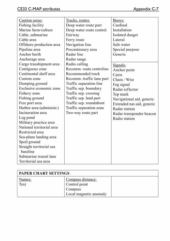
CE33 C-MAP attributes Appendix C-7
Caution areas:
Fishing facility
Marine farm/culture
Cable, submarine
Cable area
Offshore production area
Pipeline area
Anchor berth
Anchorage area
Cargo transhipment area
Contiguous zone
Continental shelf area
Custom zone
Dumping ground
Exclusive economic zone
Fishery zone
Fishing ground
Free port area
Harbor area (administr.)
Incineration area
Log pond
Military practice area
National territorial area
Restricted area
Sea-plane landing area
Spoil ground
Straight territorial sea
baseline
Submarine transit lane
Territorial sea area
Tracks, routes:
Deep water route part
Deep water route centrel.
Fairway
Ferry route
Navigation line
Precautionary area
Radar line
Radar range
Radio calling
Recomm. route centreline
Recommended track
Recomm. traffic lane part
Traffic separation line
Traffic sep. boundary
Traffic sep. crossing
Traffic sep. land part
Traffic sep. roundabout
Traffic separation zone
Two-way route part
Buoys:
Cardinal
Installation
Isolated danger
Lateral
Safe water
Special purpose
Generic
Signals:
Anchor point
Cairn
Chain / Wire
Fog signal
Radar reflector
Top mark
Navigational aid, generic
Extended nav.aid, generic
Radar station
Radar transponder beacon
Radio station
PAPER CHART SETTINGS
Names:
Text
Compass distance:
Control point
Compass
Local magnetic anomaly

Appendix C-8 CE33 C-MAP attributes
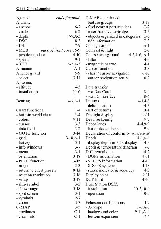
CE33 ChartSounder Index
Agents end of manualAlarms,- anchor 6-2- circle 6-2- depth 7-9,A-3- DSC 8-3- fish 7-9- MOB back of front cover, 6-9- position update 4-10- speed 9-1- XTE 6-2,A-3Almanac A-1Anchor guard 6-9- select 3-14Antenna,- altitude 4-3- installation 10-6
Bearing 4-3,A-1
Chart functions 1-4- built-in world chart 3-4- colors 9-11- cursor 3-3- data field 3-2- GOTO function 3-14- grid 3-18,A-1- hotkey 3-1- info windows 3-7- menu 3-1- orientation 3-18- PLOT function 3-15- range 3-3- return to chart presets 9-13- rotation resolution 3-18- setup 3-17- ship symbol 3-2- show range 3-18- split screen 3-1- symbols 2-7- zoom 3-3C-MAP 3-5- attributes C-1- chart info C-1
C-MAP - continued,- feature groups 3-19- find nearest port services C-2- insert/remove cartridge 3-5- objects organized in categories C-5- tide information C-3Configuration A-1Contrast & light 2-7Course over ground 4-5,4-6, A-1- filter 4-3- magnetic or true 4-1Cursor function 3-3- chart / cursor navigation 6-10- cursor navigation setup 6-2
Data transfer,- via DataCard 8-4- via PC interface 8-6Datums 4-1,4-3- delta position 4-3- list of datums B-1Daylight display 9-11Dead reckoning 9-7Decca lanes 4-4,9-9- list of decca chains 9-9Declaration of conformity end of manual
Depth 4-1,4-6- display depth in POS display 4-3Depth & temperature diagram 7-7Differential data 4-2- DGPS information 4-11- SDGPS information 4-13- SDGPS systems 4-13- status indicator & accuracy 4-2Display color 9-11DOP limit 4-10Dual Station DS33,- installation 10-5,10-9- operation 10-5
Echosounder functions 1-7- A-scope 7-6,A-3- background color 9-11,A-4- bottom expansion 7-4
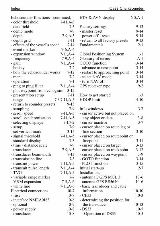
Index CE33 ChartSounder
Echosounder functions - continued,- color threshold 7-11,A-3- data field 7-3- demo mode 7-9- depth 7-9,A-3- depth grid 7-11- effects of the vessel’s speed 7-14- event marker 7-6,A-4- expansion window 7-11,A-4- frequency 7-9,A-4- gain 7-11,A-4- hotkey 7-2- how the echosounder works 7-12- menu 7-2- operation 7-1- ping to ping filter 7-11,A-4- plot waypoint from echogram 3-15- presentation setup 7-11- range 7-3,7-11,A-5- return to sounder presets 9-13- sampling 7-9- scroll speed 7-11,A-5- scroll synchronization 7-11,A-5- selecting displays 7-1,7-2- setup 7-9- set vertical mark 3-15- signal threshold 7-11,A-5- standard display 7-3- time / distance scale 7-9- transducer 7-9,A-5- transducer beamwidth 7-13- transmission line 7-3- transmit power 7-11,A-5- transmit pulse length 7-11,A-4- TVG 7-11,A-5- variable range marker 7-7- VRM expansion 7-5,A-6- white line 7-11,A-6Electrical connections 10-7- fuse 10-8- interface NMEA0183 10-8- optional 10-9- power supply 10-8- transducer 10-8
ETA & AVN display 6-5,A-1
Factory settings 9-13- master reset 9-14- power off - reset 9-14- return to all factory presets 9-13Fundamentals 2-1
Global Positioning System 1-1Glossary of terms A-1GOTO function 3-14- advance to next point 3-14- restart to approaching point 3-14- select NAV mode 3-14- turn NAV off 3-14GPS receiver type 9-2
How to get started 1-3HDOP limit 4-10
Info windows 3-7- cursor active but not placed on any object or data 3-8- cursor inactive 3-7- cursor placed on route leg or line section 3-10- cursor placed on routepoint or linepoint 3-11- cursor placed on target 3-13- cursor placed on trackpoint 3-12- cursor placed on waypoint 3-9- GOTO function 3-14- PLOT function 3-15Initial start-up 2-7Installation,- antenna DGPS MGL 3 10-6- antenna GPS RS5640 10-6- basic transducer and cable information 10-10- CE33 10-3- determining the position for the transducer 10-13- DS33 10-5 - Operation of DS33 10-5
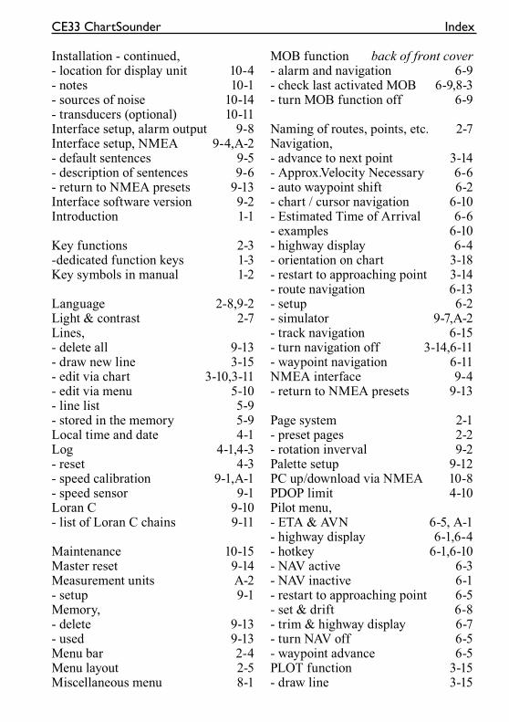
CE33 ChartSounder Index
Installation - continued,- location for display unit 10-4- notes 10-1- sources of noise 10-14- transducers (optional) 10-11Interface setup, alarm output 9-8Interface setup, NMEA 9-4,A-2- default sentences 9-5- description of sentences 9-6- return to NMEA presets 9-13Interface software version 9-2Introduction 1-1
Key functions 2-3-dedicated function keys 1-3Key symbols in manual 1-2
Language 2-8,9-2Light & contrast 2-7Lines,- delete all 9-13- draw new line 3-15- edit via chart 3-10,3-11- edit via menu 5-10- line list 5-9- stored in the memory 5-9Local time and date 4-1Log 4-1,4-3- reset 4-3- speed calibration 9-1,A-1- speed sensor 9-1Loran C 9-10- list of Loran C chains 9-11
Maintenance 10-15Master reset 9-14Measurement units A-2- setup 9-1Memory,- delete 9-13- used 9-13Menu bar 2-4Menu layout 2-5Miscellaneous menu 8-1
MOB function back of front cover- alarm and navigation 6-9- check last activated MOB 6-9,8-3- turn MOB function off 6-9
Naming of routes, points, etc. 2-7Navigation,- advance to next point 3-14- Approx.Velocity Necessary 6-6- auto waypoint shift 6-2- chart / cursor navigation 6-10- Estimated Time of Arrival 6-6- examples 6-10- highway display 6-4- orientation on chart 3-18- restart to approaching point 3-14- route navigation 6-13- setup 6-2- simulator 9-7,A-2- track navigation 6-15- turn navigation off 3-14,6-11- waypoint navigation 6-11NMEA interface 9-4- return to NMEA presets 9-13
Page system 2-1- preset pages 2-2- rotation inverval 9-2Palette setup 9-12PC up/download via NMEA 10-8PDOP limit 4-10Pilot menu,- ETA & AVN 6-5, A-1- highway display 6-1,6-4- hotkey 6-1,6-10- NAV active 6-3- NAV inactive 6-1- restart to approaching point 6-5- set & drift 6-8- trim & highway display 6-7- turn NAV off 6-5- waypoint advance 6-5PLOT function 3-15- draw line 3-15
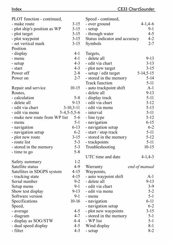
Index CE33 ChartSounder
PLOT function - continued,- make route 3-15- plot ship’s position as WP 3-15- plot target 3-15- plot waypoint 3-15- set vertical mark 3-15Position - display 4-1- menu 4-1- setup 4-3- start 4-3Power off 2-8Power on 2-7
Repair and service 10-15Routes,- calculation 5-8- delete all 9-13- edit via chart 3-10,3-11- edit via menu 5-4,5-5,5-6- make new route from WP list 5-6- menu 5-1- navigation 6-13- navigation setup 6-2- plot new route 3-15- route list 5-3- stored in the memory 5-3- time to go 5-8
Safety summary 1-2Satellite status 4-9Satellites in SDGPS system 4-15- tracking state 4-15Serial number 9-2Setup menu 9-1Show test display 9-13Software version 9-1Specifications 10-16Speed,- average 4-5- diagram 4-7- display as SOG/STW 4-4- dual speed display 4-5- filter 4-3
Speed - continued,- over ground 4-1,4-6- setup 9-1- through water 4-5Status indicator and accuracy 4-2Symbols 2-7
Targets,- delete all 9-13- edit via chart 3-13- plot new target 3-15- setup / edit target 5-14,5-15- stored in the memory 5-14Track function 5-11- auto trackpoint shift A-1- delete all 9-13- display track 5-11- edit via chart 3-12- edit via menu 5-13- interval 5-11- line type 5-12- navigation 6-15- navigation setup 6-2- start / stop track 5-11- stored in the memory 5-12- trackpoints 5-11Troubleshooting 10-15
UTC time and date 4-1,4-3
Warranty end of manualWaypoints,- auto waypoint shift A-1- delete all 9-13- edit via chart 3-9- edit via menu 5-2- menu 5-1- navigation 6-11- navigation setup 6-2- plot new waypoints 3-15- stored in the memory 5-1- WP list 5-1Wind display 8-1- setup 8-2

CE33 ChartSounder Index
Wind - continued,- wind direction 8-1- wind relative to the vessel 8-1- wind speed, relative or true 8-1
XTE - cross-track-error 5-4,5-8,6-4,A-3
Declaration of Conformity(As required by Article 6.3 of Directive 1999/5/EC-RTTE Directive)
We, Simrad Støvring AS - declare under our soleresponsibility that the following products, intended for navigation andworld-wide use aboard non-SOLAS vessels, comply with the relevant
essential requirements of Directive 1999/5/EC:
SIMRAD CE33, CP33
Chartplotters with GPS receiver
Conformity assessment under Annex II of 1999/5/EC(internal production control) has been undertaken by
Simrad Støvring ASØstre Allé 6, DK-9530 Støvring
Denmark
Telephone +45 98373499 Telefax +45 98373807
Signed ……………………............… 01 March 2002Odin Sletten, Product Manager
Garanti
SIMRAD garanterer at alle produkter er fri af fejl i materiale og udførelse, som beskrevetnedenstående:
KATEGORI “A”:•Autopiloter •Radar •Instrumenter •Navigatorer •Radiotelefoner •Plottere •Gyrokompasser inkl. sensitive elementer •Sonar-systemer •Ekkolod •Trawl Instrumentation.Disse produkter er fra købsdatoen under garanti i en periode på 24 måneder på dele og12 måneder på arbejdsløn, med undtagelse af de dele af udstyret som er beskrevet ikategori B. Dele som lys, sikringer, batterier, lejer etc. er ikke dækket under garantien.
KATEGORI “B”:•Antenner •Transducers •Trawl sensorer •Monitorer (CRT/LCD) •Radar magnetroner•Disk drev.Disse dele er under garanti for en periode på 12 måneder på dele og arbejdsløn frakøbsdatoen.
GARANTI SERVICE kan bestilles gennem autoriserede service forhandlere ellernationale distributører overalt i verden. Returnerede produkter vil efter Simradskonduite enten blive repareret eller erstattet uden beregning inden for normal arbejds-tid. Maksimalt erstatningsansvar kan ikke på nogen måde overstige kontraktprisen på detprodukt som hævdes at være defekt.
SERVICE OMBORD kan på forlangende arrangeres af den lokale autoriserede serviceforhandler eller national distributør. Arbejdsløn for reparation/udskiftning af defektemoduler/dele er uden beregning ved bekræftelse af gyldig garanti. Omkostninger vedoverarbejde, rejse og logi per dag, forsikring, told eller andre omkostninger, er kundensansvar. Yderligere omkostninger i forbindelse med udskiftning af transducere, som kanvære bringe i tørdok, dykning og foranstaltninger er ikke dækket af garantien.
GYLDIGHED: Denne garanti er kun gyldig ved fremvisning af garantibevis ellerkøbsfaktura samt udstyrets serielnummer. Installation og betjening skal være foretaget ihenhold til produktets manual. Garantiens erstatningsforpligtelse er ikke gældende forudstyr som ikke er i funktionsdygtig stand på grund af misbrug, ulykke, forsømmelse,vandskade eller uautoriseret reparation. Simrad er ikke ansvarlig for noget tab, tilfældigteller driftstab, enten det stamme fra garanti, kontrakt eller forsømmelse, eller opstået iforbindelse med salg, installation, brug og reparation af produktet. Driftstab inkluderer,men er ikke begrænset til, hel eller delvis tab af fortjeneste, skade på ejendom ellerpersonlig skade.
Ovenstående garantibetingelser har ingen indflydelse på kundens lovmæssige rettigheder.
GARANTIB
EVIS
EJE
RE
NB
EH
OL
DE
RD
ET
TE
BE
VIS
____
____
____
____
____
____
____
____
____
____
____
___
____
____
____
____
____
____
____
____
____
____
_E
JER
SKIB
/BÅ
D__
____
____
____
____
____
____
____
____
____
____
___
____
____
____
____
____
____
____
____
____
____
___
AD
RE
SS
EH
JEM
ST
ED
____
____
____
____
____
____
____
____
____
____
___
TY
PE
____
____
____
____
____
____
____
____
____
____
____
____
____
____
__U
DS
TY
R__
____
____
____
____
____
____
____
____
____
____
____
____
____
____
____
____
____
____
____
____
____
____
____
____
____
____
____
____
____
____
____
____
____
____
____
____
____
____
____
____
____
____
____
____
____
____
____
JA:_
____
___
NE
J:__
____
__K
ØB
SD
AT
OIN
ST
AL
LA
TIO
NS
DA
TO
INS
TR
UK
TIO
NI
BR
UG
AF
UD
ST
YR
___________________________________________
AU
TO
RIS
ER
ET
INS
TA
LL
AT
ØR
/FO
RH
AN
DL
ER
SS
TE
MP
EL
Sim
rad
Stø
vrin
g A
SØ
stre
Allé
6D
K-9
530
Stø
vrin
gD
anm
ark
SER
IEL
NR
.
SIM
RA
Dga
rant
erer
atal
lepr
oduk
ter
erfr
iaf
fejl
imat
eria
leog
udfø
rels
e,so
mbe
skre
vetp
åom
ståe
nde
side
.
rive
sud
GARANTIB
EVIS
Sen
des
tilN
AT
ION
AL
DIS
TR
IBU
TØ
R(s
eom
ståe
nde)
sam
men
med
inst
alla
tion
srap
port
IND
EN
14D
AG
Efr
ain
stal
lati
onsd
ato.
____
____
____
____
____
____
____
____
____
____
____
___
____
____
____
____
____
____
____
____
____
____
_E
JER
SKIB
/BÅ
D__
____
____
____
____
____
____
____
____
____
____
___
____
____
____
____
____
____
____
____
____
____
___
AD
RE
SS
EH
JEM
ST
ED
____
____
____
____
____
____
____
____
____
____
____
___
____
____
____
____
____
____
____
____
____
____
_T
YP
E
____
____
____
____
____
____
____
____
____
____
____
____
____
____
__U
DS
TY
R__
____
____
____
____
____
____
____
____
____
____
____
____
____
____
____
____
____
____
____
____
____
____
____
____
____
____
____
____
____
____
____
____
____
____
____
____
____
____
____
____
____
____
____
____
____
____
____
____
____
____
____
____
____
____
____
KØ
BS
DA
TO
INS
TA
LL
AT
ION
SD
AT
O
____
____
____
____
____
____
____
____
____
____
____
____
____
____
____
____
____
____
____
____
(KØ
BE
RS
UN
DE
RS
KR
IFT
)(F
OR
HA
ND
LE
RS
UN
DE
RS
KR
IFT
)
Sim
rad
Stø
vrin
g A
SØ
stre
All
é6
DK
-953
0S
tøvr
ing
Dan
mar
k
SER
IEL
NR
.

NA
TIO
NA
LS
IMR
AD
DIS
TR
IBU
TØ
R:
____
____
____
____
____
____
____
____
____
____
____
____
____
____
____
____
____
____
_
____
____
____
____
____
____
____
____
____
____
____
____
____
____
____
____
____
____
_
____
____
____
____
____
____
____
____
____
____
____
____
____
____
____
____
____
____
_
____
____
____
____
____
____
____
____
____
____
____
____
____
____
____
____
____
____
_
PO
RT
O