Embed Size (px)
Citation preview

On / Off
Zone
Partition
Bypass /Activate
System Pause
Test
AlarmMemory
Contrast
Enter
Outdoor Clock Trouble
RingOn-siteListening
Siren Delay PowerFailure
Entry / ExitDelay
C / F
Cancel
Password
ABC
ID Message
DEF
MNOJKLGHI
PRS TUV WXY
QZ
Arm / Disarm
(...)
Rev.06890-00014

2 AA-800 / AA-800T rev.06
WARNING: the warranty can be void if the Agri-Alert 800T or Agri-Alert-800 is usedin a manner not specified by the manufacturer.
Manufacturer:
Viatron Electronics3514 1st Street,
St-Hubert (Quebec)CanadaJ3Y 8Y5

3AA-800 / AA-800T rev.06
Table of Contents
CHAPTER ONE: INSTALLATION................................................................ 61.1 INSTALLATION PROCEDURE.............................................................................. 61.2 MOUNTING THE EQUIPMENT ............................................................................ 71.3 CONNECTING THE EQUIPMENT ......................................................................... 9
1.3.1 Sensors ............................................................................................... 91.3.2 Supply Inputs ..................................................................................... 10
1.3.2.1 AC Power Connection .................................................................... 101.3.2.2 Backup Battery Connection ............................................................ 10
1.3.3 Terminal Outputs ................................................................................ 101.3.3.1 Siren Output ................................................................................. 101.3.3.2 12VDC Output (AA 800T only) ....................................................... 10
1.3.4 Phone Hookup .................................................................................... 111.3.5 Connecting the Earth Ground................................................................ 12
CHAPTER TWO: USER INTERFACE ......................................................... 132.1 FRONT PANEL.................................................................................................132.2 MEANING OF STATUS LEDS.............................................................................142.3 DISPLAYING A PARAMETER .............................................................................142.4 MODIFYING A PARAMETER ..............................................................................152.5 HOW TO USE THE MENUS ...............................................................................16
CHAPTER THREE: SYSTEM INITIALIZATION ............................................. 173.1 INSTALLER PASSWORD ...................................................................................173.2 CONFIGURING THE ZONES ...............................................................................18
3.2.1 Dry Contact Input ............................................................................... 213.2.2 Dry Contact Burglar Input .................................................................... 243.2.3 Temperature Input .............................................................................. 263.2.4 Pulse Count Input ................................................................................ 283.2.5 Setting the Reset Time ........................................................................ 313.2.6 Disable the Siren ................................................................................ 33
3.3 SYSTEM CLOCK .............................................................................................343.4 USER ID MESSAGE .........................................................................................353.5 TEMPERATURE UNITS .....................................................................................363.6 DISPLAY CONTRAST .......................................................................................373.7 DEFAULT VALUES ...........................................................................................383.8 TEST PROCEDURE ..........................................................................................413.9 TROUBLE INFORMATION ..................................................................................413.10 VIEWING SOFTWARE VERSION .......................................................................423.11 STANDBY MODE ...........................................................................................43
CHAPTER FOUR: COMMUNICATION PARAMETERS ................................... 444.1 DIALING INFORMATION ...................................................................................44
4.1.1 Dialing Mode and Speed ...................................................................... 454.1.1.1 Dialing Mode ................................................................................ 45

4 AA-800 / AA-800T rev.06
4.1.1.2 Tone Dialing Speed........................................................................ 464.1.1.3 Pulse Dialing Speed ....................................................................... 47
4.1.2 Line Seizure ....................................................................................... 504.1.3 Call Repetitions .................................................................................. 514.1.4 Message Repetitions ........................................................................... 524.1.5 Busy Line Tries ................................................................................... 534.1.6 Tone Delay ........................................................................................ 544.1.7 Pause Delay Key ................................................................................ 554.1.8 Call Start Delay .................................................................................. 564.1.9 Time Between Calls ............................................................................ 574.1.10 Alarm Recall Time............................................................................. 584.1.11 Restore Calls .................................................................................... 594.1.12 Disable the Dialer ............................................................................. 60
4.2 PHONE NUMBERS ...........................................................................................614.3 ON SITE LISTENING .........................................................................................654.4 RINGS / ANSWERING MACHINE........................................................................664.5 SYSTEM’S VOICE MUTE ..................................................................................67
CHAPTER FIVE: ALARM PARAMETERS ................................................... 695.1 ALARM VALIDATION: SUMMARY OF EVENTS ...................................................695.2 SYSTEM ALARMS ...........................................................................................70
5.2.1 Backup Battery Voltage Readout .......................................................... 705.3 OUTDOOR TEMPERATURE COMPENSATION ON TEMPERATURE ALARMS .............725.4 ALARM MEMORY...........................................................................................775.5 ZONE STATUS DISPLAY...................................................................................78
5.5.1 Viewing and Modifying Dry Contact Zones ............................................. 785.5.2 Viewing and Modifying Temperature Zones ............................................ 795.5.3 Viewing and Modifying Pulse Count Zones ............................................. 82
5.6 PARTITIONS ...................................................................................................845.7 BYPASS / ACTIVATE FUNCTION .......................................................................865.8 ENTRY DELAY ................................................................................................885.9 EXIT DELAY....................................................................................................895.10 SIREN DELAY................................................................................................90TROUBLESHOOTING GUIDE .................................................................... 91APPENDIX A: FUSE TYPES .................................................................... 93APPENDIX B: MAXIMUM WIRE LENGTHS ............................................... 93APPENDIX C: BACKUP BATTERY LIFE SPAN............................................ 93GLOSSARY OF TERMS ........................................................................... 94WIRING DIAGRAMS ............................................................................... 96TECHNICAL SPECIFICATIONS ................................................................. 97REGISTRATION CARD ............................................................................ 99

5AA-800 / AA-800T rev.06
NOTICE
Every effort has been made to ensure that this manual is complete, accurate and up-to-date. The information contained in it is however subject to change without noticedue to further developments.
LIST OF TABLES AND FIGURES
Figure 1: Mounting the Enclosures ..................................................................... 7Figure 2: Location of Mounting Holes ................................................................. 8Figure 3: Electrical Knockouts for Battery Hookup............................................... 9Figure 4: Phone Hookup with Line Seizure ........................................................ 11Figure 5: Phone Hookup without Line Seizure ................................................... 11Figure 6: Illustration of Recognition Time.......................................................... 19Figure 7: Normally Open Circuits With EOLR ..................................................... 21Figure 8: Examples of Zone Connections Without EOLR ..................................... 21Figure 9: Examples of Zone Connections with EOLR .......................................... 22Figure 10: Temperature Input ........................................................................... 26Figure 11: Illustration of Reset Time .................................................................. 31Figure 12: Pulse Timing Parameters................................................................... 45Figure 13: Waiting Time .................................................................................. 54Figure 14: Calling a Pager Number .................................................................... 64Figure 15: Outdoor Temperature Compensation .................................................. 72Figure 16: Critical Temperature Monitoring ........................................................ 73Figure 17: Monitoring the Indoor-Outdoor Temperature Differences ....................... 73Figure 18: Example of Partitioning ..................................................................... 84
Table 1: Default Values ................................................................................ 39Table 2: Pager Codes Used by the Agri-Alert System ........................................ 63Table 3: System Alarms ................................................................................ 70

6 AA-800 / AA-800T rev.06
CHAPTER ONE: INSTALLATION
1.1 INSTALLATION PROCEDURE
What You Need:- Agri-Alert system including independent battery enclosure
- 12VDC / 7.5AH sealed lead acid battery
- 16.5VAC/40VA transformer
TO AVOID ELECTRICAL SHOCKS AND EQUIPMENT DAMAGE, TURNOFF THE BREAKER ON WHICH IS CONNECTED THE UNIT BEFORECONFIGURING THE MAIN BOARD OR MAKING CONNECTIONS TOTHE TERMINALS.
o Step 1: Determine where you want to install the system. You need anunswitched AC power outlet and a telephone plug nearby to operate the system.
o Step 2: Make a list of all the sensor inputs you will be using with the Agri-Alertsystem.
o Step 3: Mount the Agri-Alert system and the battery enclosure on the wall (seeSection 1.2).
o Step 4: Connect a ground wire to the main ground of the system (see Section1.3.5).
o Step 5: Hook up the sensors, the telephone line and the siren (if used) to theterminals on the main board in the Agri-Alert enclosure (see Section 1.3).
o Step 6: Hook up the battery (see 1.3.2.2) and plug the transformer into an ACpower outlet.
!WARNING
!WARNING
Caution. Carefully read the following text for it contains important infor-mation which, if ignored, may cause the controller to operate improperly.
Pay attention. The following text contains very useful information.
KEYS TO SYMBOLS IN THE MANUAL

7AA-800 / AA-800T rev.06
Figure 1: Mounting the Enclosures
1.2 MOUNTING THE EQUIPMENT
The Agri-Alert system should be mounted on a wall as shown in the figure below. TheAgri-Alert enclosure is opened by sliding the latch upwards and pulling. The batteryenclosure is opened by pulling on the latch. Use 3/16” diameter screws to mounteach enclosure on the wall. Fasten the black caps onto the mounting holes once thescrews are tightened. Make sure the covers of the two boxes can be opened easily.The battery enclosure has ventilation openings on the sides. Make sure they are notobstructed. Mount the battery enclosure 4” from the Agri-Alert enclosure. Use theplastic tubing provided to run the wires from the battery to the alarm system. Thesewires are provided with the system. The bare end hooks up to the Agri-Alert system.Electrical knockouts are located on the bottom of each enclosure for running the tube.Use a screwdriver and a hammer to punch out the holes. Use the cable holders pro-vided to connect the tube to the enclosure. This prevents water from seeping into theenclosure.

8 AA-800 / AA-800T rev.06
IF OUTDOOR CONNECTIONS ARE USED, MOUNT THE ENCLO-SURE AS CLOSE AS POSSIBLE TO THE ENTRY POINT OF THEOUTDOOR WIRING.
!CAUTION
Figure 2: Location of Mounting Holes
AGRI-ALERT BATTERY

9AA-800 / AA-800T rev.06
Sensor Inputs on the Main Board:
GNDZ1 Z2 GNDZ3 Z4 Z5 Z6 Z7 Z8
ZONE INPUTS
GND GND
1.3 CONNECTING THE EQUIPMENT
When connecting the equipment to the terminals provided on the main board and theextension cards, strip the wires as little as possible (about 1/4”) to avoid electricalshorts. Avoid running wires too close to the heat sink (H5 and H6). Once the wiresare connected, run them through the electrical knockouts provided on the bottom ofthe Agri-Alert enclosure and use a cable holder (2 cable holders are provided for thebattery connections and 2 additional cable holders are included with the system —you can order additional cable holders from your dealer if needed). Additional holesmade in the enclosure will void the warranty.
1.3.1 Sensors
The terminals used for sensor inputs are numbered Z1, Z2, Z3, etc. on the mainboard. Connect each sensor to a Z terminal and to the ground terminal (GND). Notethat each ground terminal is used by two zones; for example, Z1 and Z2 use thesame ground. Make sure each sensor is connected to the proper ground. Falsealarms can result if the ground wires are not properly connected.
Figure 3: Electrical Knockouts for Battery Hookup
AGRI-ALERT BATTERY
BATTERY HOOK-UP
TUBING
BATTERYWIRES
TERMINALS

10 AA-800 / AA-800T rev.06
BATTERY+
SUPPLY INPUTS
-
16VAC
BLACKRED
BATTERYWALL MOUNTTRANSFORMER
REDWIRE(+)
BLACKWIRE(—)
1.3.2 Supply Inputs
1.3.2.1 AC Power Connection
The terminals marked 16VAC on the main board are used for connecting the trans-former. The transformer provided with the system is a 16.5VAC/40VA transformer.It must be plugged into a 120VAC/60Hz outlet. The F6 and F7 fuses (5A fast blow)are connected to this input. Make sure the power source is unswitched (i.e. there isno switch on the power outlet).
1.3.2.2 Backup Battery Connection
The terminals marked BATTERY are used for the backupbattery. The Agri-Alert system uses a 12VDC / 7.5AHsealed lead acid battery. No other type of battery canbe used. The F28 fuse (5A slow blow) is connected tothis input. The battery wires run through the tubeprovided, as shown in Figure 3. Make sure the positivewire of the battery is connected to the positive terminal.See Appendix C for normal battery life spans.
1.3.3 Terminal Outputs
1.3.3.1 Siren Output
The terminals marked SIREN are for the siren. The voltage supplied is 12VDC with amaximum current of 1.5A. Note that the battery must be hooked up if a siren is used.The F8 fuse (2A slow blow) is connected to this output. Make sure the positive wireis connected to the positive terminal of the siren. The siren circuit is monitored by theAgri-Alert system for defects and wire troubles. This may not work properly if theimpedance of the siren is too high. If this is the case,you can add a 1.5k resistor (1/2W) to the siren circuitas close to the siren as possible. If no siren is con-nected, a 1.5k resistor (1/2W) (included with the sys-tem) must be wired to the siren output.
1.3.3.2 12VDC Output (AA 800T only)
The terminals marked 12VDC provide 12VDC with a maximumcurrent of 750mA. This can be used to power other accessoriessuch as temperature controllers. The F4 fuse (1A fast blow) isconnected to this output. In the event of a power failure, thebattery back-up provides 12VDC to this line. Make sure the posi-tive wire is connected to the positive terminal of your device.
1.5 k1/2 W
OUTPUTS
12VDC+ -
SIREN+ -

11AA-800 / AA-800T rev.06
Figure 5: Phone Hookup without Line Seizure
WALL JACK
R T TR
PLUG
TIP
RING
THE TIP WIRE IS THE ONE WITHTHE MOST POSITIVE VOLTAGEREADING ON A VOLTMETER
Figure 4: Phone Hookup with Line Seizure
WALL JACK
PLUG
TO ALL PHONE LINES
1
R T
2
3
4 5
6
7
8
R1
T1
TR
R1 T1
1.3.4 Phone Hookup
Two types of phone hookups are possible. In the simplest case, the Agri-Alert is con-nected to the phone lines using an ordinary 6 contact phone jack (Canada: CA11; USA:RJ11). The two wires from the phone line are connected to the LINE terminals marked Rand T. In this configuration, the user has priority over the system when using the phoneline: the system will wait for the line to free up before dialing out.
The best method is to use a line seizure modular jack designed for use with alarm systems(Canada: CA31A or CA38A; USA: RJ31A or RJ38A). In this case, the system has priorityover other users when dialing out. A line seizure kit is available from your dealer (partnumber 70-10212). The connections for this type of plug are shown in the figure below.This plug disconnects all other phones on the line when dialing out in an emergency. Inorder to do this, you must tap the phone line at its point of entry in the building.

12 AA-800 / AA-800T rev.06
IF OUTDOOR CONNECTIONS ARE USED, MOUNT THE ENCLOSUREAS CLOSE AS POSSIBLE TO THE ENTRY POINT OF THE OUTDOORWIRING.
!CAUTION
AN IMPROPER EARTH GROUND CONNECTION IMMEDIATELYVOIDS THE SYSTEM WARRANTY WITHOUT FURTHER NOTICE.
!WARNING
1.3.5 Connecting the Earth Ground
The earth ground terminal provides a ground for the Agri-Alert system. Use a rod atleast 5/8” (1.6cm) in diameter at least 10’ (3m) long. The rod must have a cleanmetal surface free of paint, enamel or other non-conducting substances. Drive therod at least 10’ (3m) into the ground. If the bedrock is more than 47” (1.2m) deep,drive the rod into the ground to bedrock level and bury any remainder horizontally atleast 2’ (600mm) below ground level. If the bedrock is less than 47” (1.2m) deep,bury the rod horizontally at least 2’ (600 mm) below ground level.
(ref. article 10-702, 3d of the Canadian Electricity Code C22.10-99)
Use a CSA certified wire of TEW type or a UL certified wire of type 1015: Green/yellow, #12AWG, 600V, 105°C insulated wire. We suggest using a Belden #9912(color code #189) or equivalent.
The rod must be connected to the wire described above. It is recommended to let therod going out of the ground to connect it. The rod length must not exceed 50’ (15m).
It is extremely important that the earth ground terminal be connected toa proper ground to protect the electronic components from damage dueto lightning surges and electrostatic discharges. Do not use the electricalground for this purpose.

13AA-800 / AA-800T rev.06
CHAPTER TWO: USER INTERFACE
The system displays and prompts for information by using the alphanumeric screen.The keypad is used for data entry and for enabling and disabling the various systemfunctions. The speaker on the front panel delivers voice messages. A built-in piezo-electric warns of illegal entries (3 short beeps) and beeps once when a valid key ispressed. The integrated microphone on the front panel is used to record the user IDmessage and provide on-site listening. The status of some subsystems is displayedusing LEDs on the front panel.
2.1 FRONT PANEL
1 - Display Screen — An alphanumeric display used to provide information andprompt for inputs.
2 - Cursor Keys — Used to step through menu items during data entry and for delet-ing the last character entered.
3 - Zone Status LEDs — Off: DISABLED; On: ACTIVATED; Slow Blinking: BYPASSED;Fast Blinking: ALARM.
4 - Speaker — System identification and alarm messages.
5 - Integrated Microphone — Records the ID message and provides on-site listeninginput.
6 - Keypad — User inputs and information requests.
7 - System LEDs — Status of various subsystems (see table on following page).

14 AA-800 / AA-800T rev.06
2.2 MEANING OF STATUS LEDS
2.3 DISPLAYING A PARAMETER
When you select a parameter to input or modify, the system begins by displaying thecurrent value or status of the parameter. If the message to display is longer than thesize of the window, it will be scrolled to the left. The display pauses at the end ofeach screen to allow time to read the message. You can exit prematurely from adisplay sequence at any time by pressing the Cancel key. This will place you inprogram mode and allow you to modify the parameter values (see next section). Toexit from this function as well, press the Cancel key once again. If a parameter is notcompletely defined when you try to display it, the message INCOMPLETE DATA ap-pears on the screen. This may be an indication that the system will not behave asexpected. If, for example, a zone input is not completely configured, the system will
!
"
#$%& '(
)
*+

15AA-800 / AA-800T rev.06
ENTER NEW DELAY_ MIN: _ _ SEC
RANGE FROM(0 .. 5 MIN, 0 .. 59 SEC)
TO MODIFY. . . . . (↵↵↵↵↵ )TO QUIT. . . . . . . (X)
not monitor the zone for alarm conditions. Before enabling the system for normaloperation, make sure all parameters are properly defined. In the case of phone num-bers and zones, the system will display a message every 3 seconds telling the userwhich zones and phone numbers are incomplete. To exit from the warning display,press the Cancel key.
2.4 MODIFYING A PARAMETER
If you have selected a parameter and the display sequence is now finished, you canbegin modifying the parameter values. The following screen appears on the display:
This screen is also displayed if the display sequence described above was cancelledprematurely. If you want to modify the parameter values at this point, press the Enter
key to modify the parameter. The system will prompt for the information re-quired to define the parameter. When the parameter is defined by a numerical value,a range of possible values is displayed. For example, if you select the Exit Delayparameter followed by MODIFY, the system responds:
The number of spaces provided for input corresponds to the maximum number ofdigits allowed. In this example, one space is provided for the minutes and 2 spacesare provided for the seconds. The cursor positions itself on the first space and blinksuntil a digit is entered. If no response is given within 2 minutes, the system will can-cel the input session and return to the Date/Time display. If more than one value isrequired in the same screen (in this example: hours and minutes), press Enter afterentering the first value to step to the following one. To enter a zero value, you cannotsimply press Enter; you must type 0 Enter.
16 AA-800 / AA-800T rev.06
PASSWORDMASTER
PASSWORDSTATUS
DATE . . . . . . . . . (1)TIME . . . . . . . . . (2)
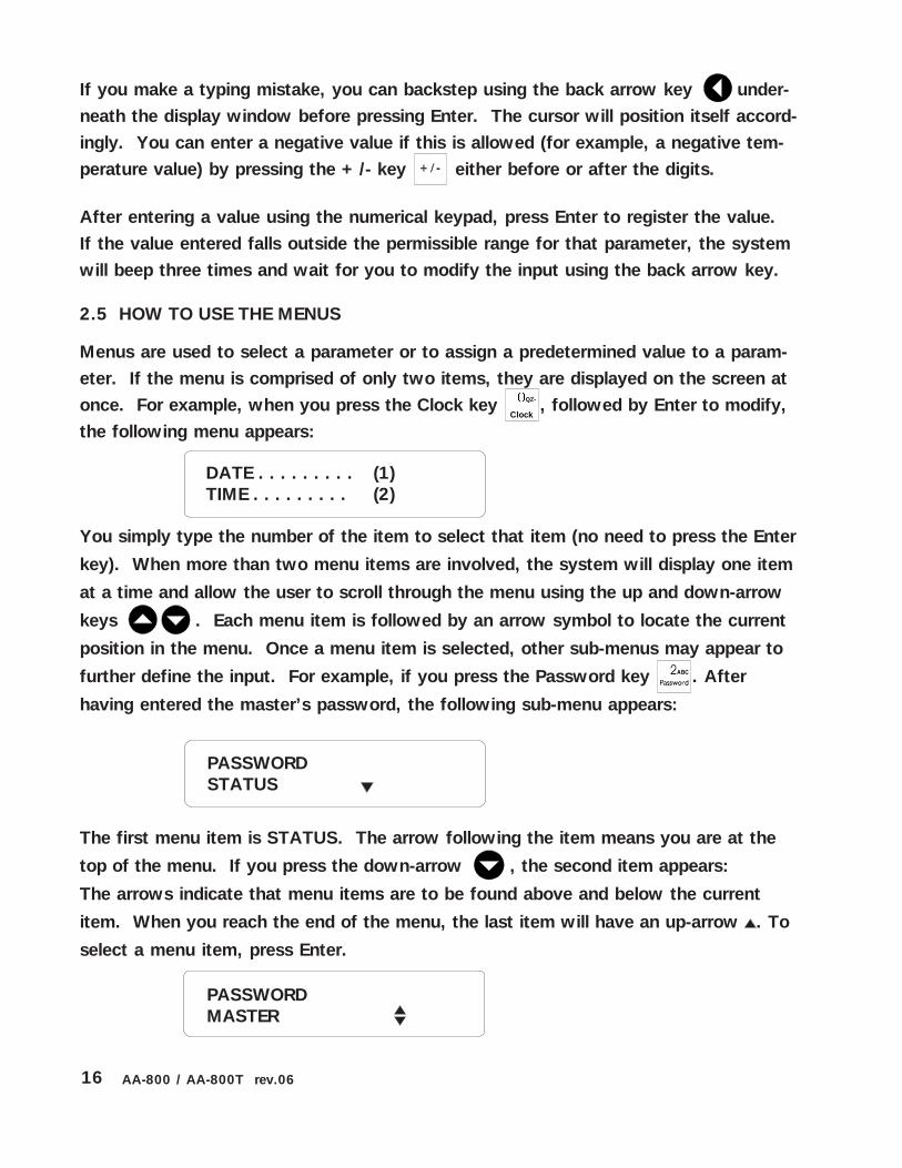
If you make a typing mistake, you can backstep using the back arrow key under-neath the display window before pressing Enter. The cursor will position itself accord-ingly. You can enter a negative value if this is allowed (for example, a negative tem-perature value) by pressing the +/- key either before or after the digits.
After entering a value using the numerical keypad, press Enter to register the value.If the value entered falls outside the permissible range for that parameter, the systemwill beep three times and wait for you to modify the input using the back arrow key.
2.5 HOW TO USE THE MENUS
Menus are used to select a parameter or to assign a predetermined value to a param-eter. If the menu is comprised of only two items, they are displayed on the screen atonce. For example, when you press the Clock key QZ-
Clock, followed by Enter to modify,
the following menu appears:
You simply type the number of the item to select that item (no need to press the Enter
key). When more than two menu items are involved, the system will display one item
at a time and allow the user to scroll through the menu using the up and down-arrow
keys . Each menu item is followed by an arrow symbol to locate the current
position in the menu. Once a menu item is selected, other sub-menus may appear to
further define the input. For example, if you press the Password key . After
having entered the master’s password, the following sub-menu appears:
The first menu item is STATUS. The arrow following the item means you are at the
top of the menu. If you press the down-arrow , the second item appears:
The arrows indicate that menu items are to be found above and below the current
item. When you reach the end of the menu, the last item will have an up-arrow . To
select a menu item, press Enter.

17AA-800 / AA-800T rev.06
CHAPTER THREE: SYSTEM INITIALIZATION
3.1 INSTALLER PASSWORD
The system uses a special installer password to restrict access to certain initializationfunctions. This password must be entered when the SYSTEM menu is selected. Bydefault, the installer password is set to 0801.
To change the installer password:
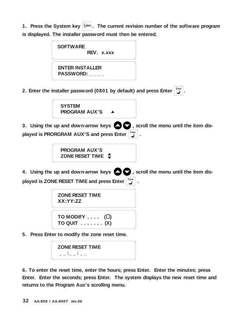
1. Press the System key . The current revision number of the software program
is displayed. The installer’s password must be entered.
2. Enter the installer’s password (0801 by default) and press Enter .
3. Using the up and down-arrow keys , scroll the menu until the item dis-
played is PRORGRAM AUX’S and press Enter .
4. Using the up and down-arrow keys , scroll the menu until the item dis-
played is INST. PASSWORD and press Enter .
5. Enter a four-digit code and press Enter . The system prompts for the pass-
word a second time.
SOFTWAREREV. x.xxx
ENTER INSTALLERPASSWORD: _ _ _ _
SYSTEMPROGRAM AUX’S
ENTER NEWPASSWORD: _ _ _ _
PROGRAM AUX’SINST. PASSWORD

18 AA-800 / AA-800T rev.06
Recognition Time: This is the time an alarm input must be active before it constitutesa valid alarm condition. It is used to configure all alarm inputs except pulse count andburglar inputs. Figure 6 below illustrates this. At “A”, an alarm situation occurs whenthe temperature exceeds the high set point. At “B”, the temperature returns to nor-mal. However, only 5 seconds have elapsed and the recognition time is 10 seconds.Therefore, no alarm occurs. At “C”, a new alarm situation occurs. At “D”, (22 - 12)= 10 seconds have elapsed; the recognition time has elapsed and an alarm is re-ported. The recognition time ranges from 0 to 59 hours, 0 to 59 minutes, 0 to 59seconds. The default is 1 minute on zones 1-8.
6. Re-enter the four-digit code and press Enter . The system saves the new
password and returns to the Program Aux’s scrolling menu.
3.2 CONFIGURING THE ZONES
The Agri-Alert system is a monitoring device used to detect alarm conditions. Differ-ent types of sensors can be connected to it. When an alarm is detected on any one ofthe inputs, the system reports the alarm on-site and starts the dialout sequence. Eachalarm input can be enabled or disabled separately or in conjunction with other inputs.An alarm stays active until it is acknowledged by a user, either on-site or over thephone. When an alarm occurs, the system stores all the relevant information: thenumber of the input, the type of alarm and the date and time of occurrence. Whenthe alarm is acknowledged, the system also stores the user who acknowledged thealarm and the date and time of acknowledgement.
Zone Definition: A zone is an input configured to respond to the type of sensor con-nected to it. Sensors are installed by the user to detect alarm conditions. The Agri-Alert system allows up to 8 different zones. The alarm types supported are dry con-tact, dry contact burglar, temperature and pulse count. A reset time is defined for allzones. The other parameters apply to each individual zone, i.e. the recognition time,the siren enable and the dialout sequence enable. The recognition time does not applyto dry contact burglar zones. In the case of a pulse count alarm, the recognition timeis replaced by a high and low set point and an observation length. If any one of theseparameters is not entered when a zone is configured, the system will display INCOM-PLETE DATA whenever the parameter definitions are displayed for that zone. Notethat when you reconfigure a zone, the system erases the alarm memory for all zones.Once a zone is configured, it must be activated by the user to start alarm detection onthat zone. The following parameters are used for defining zones:
ENTER AGAIN: _ _ _ _

19AA-800 / AA-800T rev.06
CONFIGURING THE ZONES
1. Press the System key . The current revision number of the software program
is displayed. The installer password must then be entered.
2. Enter the installer password (0801 by default) and press Enter .
3. Press Enter once again to select PROGRAM ZONES.
4. Type the number of the zone to define or modify and press Enter. The currentdefinitions for this zone are displayed. Default settings for zones are given in Section3.7. To exit the display function, press Cancel.
Figure 6: Illustration of Recognition Time
High Set Point
Low Set Point
Temperature
Time
A B
D
Alarm
Recognition Time = 10 S
C
0 S 5 S 12 S 22 S
ALARM
NO ALARM
ALARM
SOFTWAREREV. x.xxx
ENTER INSTALLERPASSWORD: _ _ _ _
SYSTEMPROGRAM ZONES
SELECT ZONE(1 .. 8): _

20 AA-800 / AA-800T rev.06
5. Press Enter to modify the zone or Cancel to exit this function. If the zone selectedis the outdoor probe used for the outdoor temperature compensation feature and thecompensation feature is currently enabled, the system displays the message: DEACTI-VATE OUTDOOR STATUS. If you want to use the compensation feature, you willhave to assign another probe as the outdoor probe (See Section 5.3). The systembeeps four times and displays the message: WARNING! ALARM MEMORY WILL BELOST! Each time a zone is reconfigured, the alarm memory associated with all zoneconfigurations is erased.
The different types of sensors are presented in a scrolling menu. Use the up and
down arrow keys to select the desired type and press Enter .
The following sections describe the input sequence for each of the sensor types.
TO MODIFY. . . . . (↵↵↵↵↵ )TO QUIT. . . . . . . (X)
TYPE OF SENSORDRY CONTACT?

21AA-800 / AA-800T rev.06
3.2.1 Dry Contact Input
Definition: Dry contacts can be either normally open (NO) or normally closed (NC)circuits. In addition, they can be configured for an end of line resistor (EOLR). Addingan end of line resistor will help the system detect wiring problems. This is illustratedin the figure below. In the center diagram, an open wire has occurred. The systemdetects this by reading the resistance on the circuit. The “Trouble” LED on the frontpanel will turn on when this happens. Figure 7 shows three possible states for anormally open circuit with EOLR. Figures 8 and 9 show examples of zone connec-tions. Note that when you add an EOLR to a circuit, the resistor must be connectedto the sensor that is furthest from the Agri-Alert system.
Figure 7: Normally Open Circuits With EOLR
ALARMWIRE TROUBLENORMAL
1.5 kΩ1/2 W
AGRI-ALERT
OPENCIRCUIT
1.5 kΩ1/2 W
1.5 kΩ1/2 W
Figure 8: Examples of Zone Connections Without EOLR
GND Z8Z7GND Z8Z7
NORMALLY CLOSED CIRCUIT NORMALLY OPEN CIRCUIT

22 AA-800 / AA-800T rev.06
Setting:
TYPE OF SENSORDRY CONTACT
6. Using the up and down-arrow keys , scroll the menu until the item dis-
played is DRY CONTACT and press Enter .
Figure 9: Examples of Zone Connections with EOLR
1.5 kΩ1/2 W
GND Z8Z7
N.C. CIRCUIT WITH EOLR
GND Z8Z7
1.5 kΩ1/2 W
N.O. CIRCUIT WITH EOLR
BURGLAR ZONE?
7. Type 2 for an ordinary dry contact input.
NORM. OPEN . . . . . . . . (1)NORM. CLOSED. . . . . . . (2)
YES . . . . . . . . . . (1)NO . . . . . . . . . . (2)

23AA-800 / AA-800T rev.06
8. Type 1 or 2 according to the desired configuration.
9. Type 1 to configure the input without an end of line resistor. Type 2 to configurethe input with an end of line resistor.
10. To enter the recognition time, enter the hours; press Enter. Enter the minutes;press Enter. Enter the seconds; press Enter. The system returns ot the zone numberprompt (step 4).
RECOGNITION TIME
RECOGNITION TIME _ _ :_ _ : _ _
RANGE FROM(0 .. 59 HR, 0 .. 59 MIN, 0 .. 59 SEC)
W/O RESISTOR . . (1)W/ RESISTOR . . . (2)

24 AA-800 / AA-800T rev.06
3.2.2 Dry Contact Burglar Input
Definition: Dry contact inputs can be configured as burglar zones. These zones arearmed or disarmed as a group using a password. The connections used are exactly asexplained for dry contact inputs (see Section 3.2.1). Two types of configurations arepossible depending on when alarms are to be declared. In an instant burglar zone,alarms are declared as soon as they are detected. In a delay burglar zone, alarms aredeclared only after an Entry Delay has elapsed. In this way, the authorized user hastime to disarm the burglar zones before an alarm is declared. This delay is common toall delay burglar zones. Similarly, all zones are armed after the Exit Delay haselapsed. No recognition time is needed for this type of zone; alarms are validated assoon as detected. The key sequence for arming or disarming is as follows:
followed by the password sequence
When the system is armed, the system starts beeping and the screen immediatelydisplays a countdown of the exit delay (in minutes and seconds). The keypad islocked at this point: the only key sequence allowed is the disarming sequence. Afterthe exit delay has elapsed, the burglar zones are armed and alarms are immediatelydeclared as they are detected for all burglar zones. The system displays the message“BURGLAR ZONES ARMED” periodically on the screen and the password feature isenabled. The Password key cannot be accessed at this point unless the burglar zonesare disarmed.
When an alarm occurs in a burglar zone with an entry delay, the screen displays acountdown of the entry delay. During this time, the piezoelectric loudspeaker beeps(the loudspeaker stops when the key sequence is entered). If no one has disarmedthe system after the entry delay has elapsed, an alarm is declared. Disarming willaffect all currently active burglar zones. The system displays the message “BUR-GLAR ZONES DISARMED” on the screen.
A burglar zone cannot be included in a partition. If a zone already belonging to apartition needs to be changed to a burglar zone, it must first be removed from thepartition. Otherwise, this is done automatically by the system.
Setting:
6. Using the up and down-arrow keys , scroll the menu until the item dis-
played is DRY CONTACT and press Enter .
TYPE OF SENSORDRY CONTACT?

25AA-800 / AA-800T rev.06
INSTANT . . . . . . . (1)DELAYED . . . . . . (2)
7. Type 1 for a burglar zone input.
8. Type 1 if no entry delay is used for this zone. Type 2 to use an entry delay for thiszone.
9. Type 1 or 2 according to the configuration desired.
10. Type 1 to configure the input without an end of line resistor. Type 2 to configurethe input with an end of line resistor. The system returns to the zone number prompt(step 4).
W/O RESISTOR . . . (1)W/ RESISTOR . . . . (2)
BURGLAR ZONE?
YES. . . . . . . . . . . (1)NO . . . . . . . . . . . (2)
NORM. OPEN . . . . (1)NORM. CLOSED . . (2)

26 AA-800 / AA-800T rev.06
HI SET POINT _ _ _ _ _ oF
7. This is the lower value of the normal temperature range. It ranges from -40 oF to149 oF (-40 oC to 65 oC) with an accuracy of 0.1 oF (0.1 oC). Enter the low set pointand press Enter. To enter a negative value, use the key, either before or afterthe digits.
8. This is the upper value of the normal temperature range. It ranges from the lowerset point to 149 oF (65 oC) with an accuracy of 0.1 oF (0.1 oC). Enter the high setpoint and press Enter. To enter a negative value, use the key, either before or
after the digits. The high set point must be greater than the low set point.
LO SET POINT _ _ _ _ _ oF
RANGE FROM(-40.0oF .. 149.0 oF)
3.2.3 Temperature Input
Definition: A temperature input responds to changes in temperature readings from asensor. A high and low set point is entered, defining a range of temperatures be-tween the set points that do not set off an alarm condition.
Setting:
TYPE OF SENSORTEMPERATURE
6. Using the up and down-arrow keys , scroll the menu until the item dis-
played is TEMPERATURE and press Enter.
Figure 10: Temperature Input
High Set Point= 85 oF
Low Set Point=70 oF
Temperature
Time
Alarm 3Alarm 2Alarm 1ALARM
NO ALARM
ALARM

27AA-800 / AA-800T rev.06
RECOGNITION TIME _ _ :_ _ : _ _
9. This is the absolute temperature limit for room temperatures. It is used in conjunc-tion with the outdoor temperature compensation feature. When the room tempera-ture reaches this point and the outdoor temperature compensation feature is enabled,an alarm is set off, no matter what the outdoor temperature is (see Section 5.3). Itranges from the high set point to 149 oF (65 oC) with an accuracy of 0.1 oF (0.1 oC).Enter the critical temperature and press Enter. To enter a negative value, use the
key, either before or after the digits.
CRITICAL TEMP. _ _ _ _ _ oF
RANGE FROM(XoF .. 149.0 oF)
RANGE FROM(0 .. 59 HR, 0 .. 59 MIN, 0 .. 59 SEC)
10. To enter the recognition time, enter the hours; press Enter. Enter the minutes;press Enter. Enter the seconds; press Enter. The system returns to the zone numberprompt (step 4).

28 AA-800 / AA-800T rev.06
3.2.4 Pulse Count Input
Definition: A pulse count input responds to changes in the pulse sensor, for examplefrom a water flow meter. A high and low set point is entered, defining a normal rangeof values between the set points for one observation length outside which an alarmcondition is reported. The user must also specify an observation length. This is thetime period used to calculate the number of pulses.
In Example 1 above, the normal range is 2 to 4 pulses within a time period defined bythe observation length. No alarm conditions are reported in this example. This typeof input is sensitive to the value of the observation length. A difference in the timeperiod used to count the pulses can change the number of alarms reported by thesystem. Example 2 below uses the same situation as Example 1, except for theobservation length which is slightly smaller. As a result of this, an alarm condition isreported. Care must be taken to set the observation length to an appropriate value.
OBSERVATIONLENGTH
Example 2: Pulse Count Input
3 PULSES
HIGH SET POINT = 4LOW SET POINT = 2
2 PULSES 2 PULSES 1 PULSE
ALARM
The system has a maximum detection rate of 1 pulse per second. In addition, thesystem cannot count more than 254 pulses within a given observation length. Thismust be accounted for when the set points and the observation length are defined. Toensure that the values are within limits, use the maximum rated pulses per unit mea-sured defined for the sensor you are using. For example, a flow meter is rated inpulses per gallon. If you calculate the maximum flow rate in gallons for your observa-tion length and multiply by the pulses per gallon, the resulting value must be less than254 pulses in order for the system to work properly. The example below sums up theprocedure.
OBSERVATIONLENGTH
Example 1: Pulse Count Input HIGH SET POINT = 4LOW SET POINT = 2
3 PULSES 3 PULSES 2 PULSES
CLOSE CONTACT
OPEN CONTACT
NEXTOBSERVATION
LENGTH
NEXTOBSERVATION
LENGTH

29AA-800 / AA-800T rev.06
Maximum Pulses Allowed
max. number of gallons obs. length
pulses gallon
maximum pulses obs. length
255 pulses
If the flow meter is rated at: 3 pulses/gallonObservation length = 1 hourNumber of gallons/hour = 1000/hour
1000 gallons 1 hour
3 pulses gallon
3000 pulses 1 hour
255 pulses
obs. length
1 hour
The resulting number of pulses exceeds the maximum allowed. The observationlength must be reduced. For example, if we try an observation length of 5 minutes,the resulting calculation becomes:
83.3 gallons 5 minutes
3 pulses gallon
250 pulses 5 minutes
255 pulses 5 minutes
7. This is the lower value of the normal pulse range. It ranges from 0 to 254. Enterthe low set point and press Enter.
Setting:
RANGE FROM(0 .. 254)
LO SET POINT_ _ _ PULSES
6. Using the up and down-arrow keys , scroll the menu until the item dis-
played is PULSE COUNT and press Enter .
HI SET POINT_ _ _ PULSES
TYPE OF SENSORPULSE COUNT

30 AA-800 / AA-800T rev.06
9. To enter the observation length, enter the hours (from 0 to 59 hours); press Enter.Enter the minutes (from 0 to 59 minutes); press Enter. Enter the seconds (from 0 to59 seconds); press Enter. The system returns to the zone number prompt (step 4).
OBSERVAT. LENGTH_ _ : _ _ : _ _
OBSERVAT. LENGTH
8. This is the upper value of the normal pulse range. It ranges from the lower setpoint to 254. The value must be greater than the low set point. Enter the high setpoint and press Enter.
RANGE FROM(0 .. 59 HR; 0 .. 59 MIN; 0 .. 59 SEC)

31AA-800 / AA-800T rev.06
3.2.5 Setting the Reset Time
Zone Reset Time: After an alarm has occurred, no new alarm can be detected on thesame input until the reset time has elapsed. The zone LED on the front panel contin-ues to flash until the reset time has elapsed and the alarm condition has returned tonormal. This parameter is used to configure all alarm inputs except pulse count in-puts. All zones use the same reset time. Using a reset time avoids reporting a suc-cession of closely related alarms as separate alarms. For example, in the case of atemperature sensor, small temperature fluctuations around one of the set points canset off a great number of separate alarms. This can be avoided if the reset time is setto an appropriate value. Figure 11 illustrates this situation. An alarm occurs at “A”when the temperature exceeds the high set point (assuming a recognition time equalto zero). This is Alarm 1.
Figure 11: Illustration of Reset Time
High Set Point
Low Set Point
Temperature
Time
A C
Reset Time = 10 S
Alarm 1
Alarm 2
40 S
B
D
0 S 30 S
Alarm 1 is reset
ALARM
NO ALARM
ALARM
No new alarms can be declared until Alarm 1 is reset. In order for this to happen, thetemperature must fall back to a normal state for at least 10 seconds (the reset time).This occurs at “C”. At “D”, a new alarm can be declared (assuming a zero recogni-tion time once again). The reset time ranges from 0 to 59 hours, 0 to 59 minutes, 0to 59 seconds. The default is 1 second.
32 AA-800 / AA-800T rev.06
1. Press the System key . The current revision number of the software program
is displayed. The installer password must then be entered.
2. Enter the installer password (0801 by default) and press Enter .
3. Using the up and down-arrow keys , scroll the menu until the item dis-
played is PRORGRAM AUX’S and press Enter .
4. Using the up and down-arrow keys , scroll the menu until the item dis-
played is ZONE RESET TIME and press Enter .
5. Press Enter to modify the zone reset time.
6. To enter the reset time, enter the hours; press Enter. Enter the minutes; pressEnter. Enter the seconds; press Enter. The system displays the new reset time andreturns to the Program Aux’s scrolling menu.
SOFTWAREREV. x.xxx
ENTER INSTALLERPASSWORD: _ _ _ _
SYSTEMPROGRAM AUX’S
ZONE RESET TIMEXX:YY:ZZ
TO MODIFY . . . . (↵↵↵↵↵ )TO QUIT . . . . . . . (X)
ZONE RESET TIME _ _ :_ _ : _ _
PROGRAM AUX’SZONE RESET TIME

33AA-800 / AA-800T rev.06
3.2.6 Disable the Siren
Definition: This function allows to disable the siren on specified zones. No siren willbe activated when an alarm occurs in these zones. By default, the siren is enabled onall zones.
1. Press the System key . The current revision number of the software program
is displayed. The installer password must then be entered.
2. Enter the installer password (0801 by default) and press Enter .
3. Using the up and down-arrow keys , scroll the menu until the item dis-
played is PRORGRAM AUX’S and press Enter .
4. Using the up and down-arrow keys , scroll the menu until the item dis-
played is SIREN DISABLED and press Enter . Zones without siren are displayed.
ENTER INSTALLERPASSWORD: _ _ _ _
SYSTEMPROGRAM AUX’S
PROGRAM AUX’SSIREN DISABLED
NO SIREN ZONE #4
5. Press Enter to ADD a zone on which the siren will be disabled or press thedown-arrow key to reactivate the dialer on a zone.
SIREN DISABLEDADD ZONE
6. Enter the desired zone number then press Enter . The system displays zones
without sirens and returns to the Program Aux’s scrolling menu.
SELECT ZONE(1 .. 8): _
34 AA-800 / AA-800T rev.06
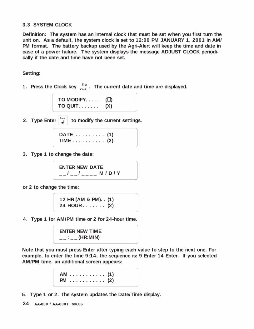
or 2 to change the time:
3. Type 1 to change the date:
2. Type Enter to modify the current settings.
3.3 SYSTEM CLOCK
Definition: The system has an internal clock that must be set when you first turn theunit on. As a default, the system clock is set to 12:00 PM JANUARY 1, 2001 in AM/PM format. The battery backup used by the Agri-Alert will keep the time and date incase of a power failure. The system displays the message ADJUST CLOCK periodi-cally if the date and time have not been set.
Setting:
1. Press the Clock key QZ-
Clock. The current date and time are displayed.
ENTER NEW DATE_ _ / _ _ / _ _ _ _ M / D / Y
DATE . . . . . . . . . (1)TIME . . . . . . . . . . (2)
ENTER NEW TIME_ _ : _ _ (HR:MIN)
Note that you must press Enter after typing each value to step to the next one. Forexample, to enter the time 9:14, the sequence is: 9 Enter 14 Enter. If you selectedAM/PM time, an additional screen appears:
AM . . . . . . . . . . . (1)PM . . . . . . . . . . . (2)
5. Type 1 or 2. The system updates the Date/Time display.
4. Type 1 for AM/PM time or 2 for 24-hour time.
12 HR (AM & PM). . (1)24 HOUR . . . . . . . (2)
TO MODIFY. . . . . (↵↵↵↵↵ )TO QUIT. . . . . . . (X)

35AA-800 / AA-800T rev.06
3.4 USER ID MESSAGE
Definition: When giving status reports and alarm messages, the system identifiesitself with a voice recording provided by the user.
Setting:
1. Press the ID message key DEF
ID message. The current ID message is played over the
speaker on the front panel. If no ID message has yet been recorded, the system
displays NONE.
ID MESSAGEPLAY
2. To modify the current message, press Enter . Otherwise, press Cancel .
To Activate / Deactivate ID Message:
3. Type 1 to activate or deactivate ID Message.
ENABLE. . . . . . . . (1)DISABLE . . . . . . . (2)
4. Type 1 to enable, or 2 to disable the ID Message. The new state is displayed andthe system returns to the Date/Time display.
To Modify ID Message:
3. Type 2 to modify ID Message.
STATE . . . . . . . . (1)MESSAGE . . . . . . (2)
STATUS. . . . . . . . (1)MESSAGE . . . . . . (2)
TO MODIFY. . . . . (↵↵↵↵↵ )TO QUIT. . . . . . . (X)

36 AA-800 / AA-800T rev.06
FOR RECORDINGPRESS 3 AND HOLD
4. Press the ID message key DEF
ID message and hold while you speak the message into the
microphone on the front panel.
RECORDING07 SEC REMAINING
5. The screen will count down from a maximum of 7 seconds until the ID messagekey is released.
ID MESSAGEPLAY
6. The new message is played over the speaker and the system returns to the Date/Time display.
3.5 TEMPERATURE UNITS
Definition: Temperatures can be displayed either in Fahrenheit or Celsius units. Alltemperatures will be displayed according to this definition. The default is Fahrenheit.
Setting:
1. Press the oC/oF key TUV . The current value is displayed.
2. To modify the current temperature units, press Enter . Otherwise, press
Cancel .
o F
TO MODIFY. . . . . (↵↵↵↵↵ )TO QUIT. . . . . . . (X)

37AA-800 / AA-800T rev.06
2. Use the up-arrow key to increase the contrast. Use the down-arrow
key to decrease the contrast. When you are finished, type Enter to save the new
setting. The system displays the new setting as a percentage. The final setting is
displayed and the system returns to the Date/Time display.
CONTRAST80%
1. Press the Contrast key . The actual contrast is displayed.
3.6 DISPLAY CONTRAST
Setting:
3. Type 1 for Celsius units, or 2 for Fahrenheit units. The new units are displayedand the system returns to the Date/Time display.
CELSIUS . . . . . . . (1)FAHRENHEIT. . . . .(2)
80%TO SAVE . . . . . . . . . (↵↵↵↵↵ )

38 AA-800 / AA-800T rev.06
5. Enter 1 to set default values or 2 to cancel. The system displays the message
PLEASE WAIT while initializing the parameter values. When the screen turns back on,
the system has been initialized.
TO SET . . . . . . . . (1)TO QUIT . . . . . . . (2)
3.7 DEFAULT VALUES
Definition: The system has default values programmed for all parameters excepttelephone numbers and user passwords. These values are present when you first turnthe unit on. If you have changed some or all of the parameter values and would liketo return to the original default values initialized at the factory, follow the procedureoutlined below. All the current parameter definitions will be erased and replaced bythe default values. Table 1 gives the default values for all system parameters.
1. Press the System key . The current revision number of the software program
is displayed. The installer password must then be entered.
2. Enter the installer password (0801 by default) and press Enter .
3. Using the up and down-arrow keys , scroll the menu until the item dis-
played is PRORGRAM AUX’S and press Enter .
4. Using the up and down-arrow keys , scroll the menu until the item dis-
played is SET DEFAULTS and press Enter . The system beeps four times and
responds with the message: WARNING: ALL PARAMETERS WILL BE LOST! This
means that all the current parameter definitions will be erased and replaced by default
values.
ENTER INSTALLERPASSWORD: _ _ _ _
SYSTEMPROGRAM AUX’S
PROGRAM AUX’SSET DEFAULTS

39AA-800 / AA-800T rev.06
"!,-*-*./ 0 10 #
2#+#/! /.33)4&
+/ /.1/ /!*-+5 64/.1/
4334&,7
-/ 8"! 00+1,+
"!*,!9"-8 & :+3
*;",!,-<,!* = 34+&
,!5#/<,!*;", 8"! 00+1,+
",+!!.*<""/ : >&+4
9*"# & ?>+3
"#,;8/! & ?>+3
",+!!.*#0+@ A A+&
,+!*+0/!<,!!; 6 >&&
929"-. 6 >>4&
,+1"-. ,+ ,+1"-.
."0/ "3= "3>43>
.""-.
2/ "?: "33&3&
2*8 "&% "33&3&
!<!*,! "33= "333:33%
!" ,+<,!,"!
/! 3: ?>+3
"-" 8"! 8"!18,
"#*+"* 8"! 8"!18,
9,*!" > 34&
99*, 3: ?>3>3
9!B 3: ?>3>3
/!#*/* 3: ?> 4&3&
9*+///* 9./
#$%&*-!0
9 > ?>3?>3
"-" 8, 8"!18,
C*++-+,./+#
'9,+33= (
"00+ '#C=4(0C> '#C34 3(0C%: 0C3
"-" 8"! 8"!18,
8+*.*++-+ =,+D =&
"*,+#9."! E3> E3&E33&+3&
Table 1: Default Values

40 AA-800 / AA-800T rev.06
Default Zone Configurations
The default reset time on all zones is 1 min. with a range from 0 to 59 hours, 59
minutes, 59 seconds. By default, zone 8 is a temperature zone assigned to the out-
door probe for the outdoor temperature compensation feature.
.9*+"," #,+#9* *-*./9*
"-.1./1#,+#
1,.+"+#!-#*!#
#, #,1+,
,!0+,*+"!"*
*+-+5!; *+-+5!;15!;
-+! 8, 8, 8"!18,
,*!" 8, 8, 8"!18,
,+!!,<+#*/!
& &?>3 ?>3
?>3
";+,!+. 0C3>
'#C3&(0C?6&0C36 '#C>%36 (
"5<!5,!+. 0C>=
'#C6?4(0C?6&0C36 '#C>%36 (
#!!*#*-*./ 0C>?
'#C>:(0C?6&0C36 '#C>%36 (
41AA-800 / AA-800T rev.06
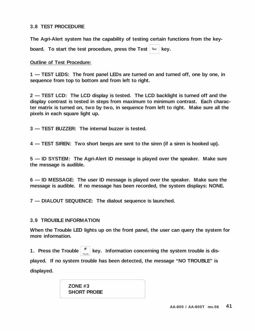
3.8 TEST PROCEDURE
The Agri-Alert system has the capability of testing certain functions from the key-
board. To start the test procedure, press the Test key.
Outline of Test Procedure:
1 — TEST LEDS: The front panel LEDs are turned on and turned off, one by one, insequence from top to bottom and from left to right.
2 — TEST LCD: The LCD display is tested. The LCD backlight is turned off and thedisplay contrast is tested in steps from maximum to minimum contrast. Each charac-ter matrix is turned on, two by two, in sequence from left to right. Make sure all thepixels in each square light up.
3 — TEST BUZZER: The internal buzzer is tested.
4 — TEST SIREN: Two short beeps are sent to the siren (if a siren is hooked up).
5 — ID SYSTEM: The Agri-Alert ID message is played over the speaker. Make surethe message is audible.
6 — ID MESSAGE: The user ID message is played over the speaker. Make sure themessage is audible. If no message has been recorded, the system displays: NONE.
7 — DIALOUT SEQUENCE: The dialout sequence is launched.
3.9 TROUBLE INFORMATION
When the Trouble LED lights up on the front panel, the user can query the system formore information.
1. Press the Trouble key. Information concerning the system trouble is dis-
played. If no system trouble has been detected, the message “NO TROUBLE” is
displayed.
ZONE #3SHORT PROBE

42 AA-800 / AA-800T rev.06
2. Type 1 to reset the trouble flag. Note that if the problem has not been corrected,the trouble LED will remain on. Type 2 to exit this function. The system returns tothe Date/Time display.
3.10 VIEWING SOFTWARE VERSION
1. Press the System key . The current revision number of the software program
is displayed. The installer password must then be entered.
2. Enter the installer password (0801 by default) and press Enter .
3. Using the up and down-arrow keys , scroll the menu until the item dis-
played is PROGRAM AUX’S and press Enter .
4. Using the up and down-arrow keys , scroll the menu until the item dis-
played is VERSION SOFTWARE and press Enter . The version of the software is
displayed. The system then returns to PROGRAM AUX’S menu.
SOFTWAREREV. x.xxx
ENTER INSTALLERPASSWORD: _ _ _ _
SYSTEMPROGRAM AUX’S
PROGRAM AUX’SVERSION SOFTWARE
SOFTWAREREV. x.xxx
TO ERASE . . . . . . (1)TO QUIT . . . . . . . (2)

43AA-800 / AA-800T rev.06
4. Type 1 to enable, or 2 to disable Standby mode. The new setting is displayed, anthe system returns to the Date/Time display.
3.11 STANDBY MODE
Definition: When the system is in standby mode, no monitoring of alarm inputs isdone. The Standby LED on the display panel and the message SYSTEM ON STANDBYare used to indicate that the system is in Standby mode. The system can automati-cally switch to standby mode when a long power failure has drained the backup bat-tery to a critical level. A pager message (code 8009) and a vocal message (“Lowbattery; system deactivated”) are sent warning that the system is about to go intostandby mode. When normal voltage is restored to the battery, the system returns toits normal mode of operations. If the system is already in standby mode when theproblem is detected, no messages are sent.
Setting:
1. Press the On/Off key . The system prompts for a password.
ENTER PASSWORD_ _ _ _
2. Type a four-digit password and press Enter . If an incorrect password is
entered, the system responds with the message “WRONG PASSWORD” and returns
to the Date/Time display. Otherwise, the system displays the current system status:
ON — the system is running normally; OFF — the system is in standby mode.
OK
STATUS: ON
3. Press Enter to modify or Cancel to quit. The system displays the new
status and returns to the Date/Time display.
TO MODIFY. . . . . (↵↵↵↵↵ )TO QUIT. . . . . . . (X)
ON. . . . . . . . . . . (1)OFF. . . . . . . . . . (2)

44 AA-800 / AA-800T rev.06
CHAPTER FOUR: COMMUNICATION PARAMETERS
4.1 DIALING INFORMATION
Definition: These parameters are used to establish communications over the tele-phone network when the dialout sequence is used.
Setting:
1. Press the System key . The current revision number of the software program
is displayed. The installer password must then be entered. Enter the installer pass-
word (0801 by default) and press Enter .
2. Using the up and down-arrow keys , scroll the menu until the item dis-
played is PRORGRAM DIALING and press Enter .
3. To modify a parameter, scroll the menu using the up and down arrow keys
until you reach the parameter you want to modify and press Enter.
SOFTWAREREV. x.xxx
SYSTEMPROGRAM ZONES
ENTER INSTALLERPASSWORD: _ _ _ _
SYSTEMPROGRAM DIALING
PROGRAM DIALINGCALL START DLY

45AA-800 / AA-800T rev.06
4.1.1 Dialing Mode and Speed
Definition: The user can choose between pulse and tone dialing. Both methods haveparameters associated with dialing speed. When changing these parameters, makesure the new values are compatible with your local telephone network. If this is notthe case, the system may not be able to dial out.
1. DTMF Speed (Dual Tone Multiple Frequency Speed): This is the dialing speed usedon tone dialing lines. Tone dialing is available only when the central telephone officeis equipped to process the tones. Some rural areas, for example, are not equipped fortone dialing. The speed corresponds to the length of the tone as well as the delaybetween digits (or interdigit time). The value ranges from 50 to 250 milliseconds.The default is 80 mS.
2. Pulse Speed: This is the dialing speed used on pulse dialing lines. When tonedialing is not available, pulse dialing is used. Pulse dialing uses a timed interval ofcircuit opening and closing called a dial pulse period. Each digit is translated as aseries of pulses. Each digit is separated by an interdigit interval (see Figure 23). Thepulse period is the sum of the make (circuit closed) and the break (circuit opened).The make ranges from 10 to 100 msec (default 39 mS); the break ranges from 10 to100 msec (default 61 mS); the interdigit ranges from 0.6 to 3 seconds (default is 0.8seconds).
Figure 12: Pulse Timing Parameters
4.1.1.1 Dialing Mode
4. Follow the procedure above for modifying the dialing parameters (Section 4.1).
When you reach the scrolling menu, use the arrow keys to select Dialing
Mode then press Enter .
PROGRAM DIALINGDIALING MODE
MAKE(CIRCUITCLOSED)
BREAK(CIR-CUITOPENED)
CONNECT
IDLE
INTERDIGIT INTERVALDIALING
“4”
DIALINGNEXT DIGIT
BREAKMAKE

46 AA-800 / AA-800T rev.06
6. Type 1 to modify tone dialing speed. The current parameter setting is displayed.
DTMF SPEED80 MSEC
6. Press Enter to modify the value or Cancel to quit.
DIALING MODETONE
5. Type 1 to modify dialing mode. The current dialing mode is displayed.
TONE . . . . . . . . . (1)PULSE . . . . . . . . (2)
7. Type 1 for tone dialing, or 2 for pulse dialing. The new setting is displayed and thesystem returns to the Program Dialing scrolling menu.
4. Follow the procedure above for modifying the dialing parameters (Section 4.1).
When you reach the scrolling menu, use the arrow keys to select Dialing
Mode then Enter .
PROGRAM DIALINGDIALING MODE
4.1.1.2 Tone Dialing Speed
5. Type 2 to modify dialing speed.
TONE . . . . . . . . . (1)PULSE . . . . . . . . (2)
MODE . . . . . . . . (1)SPEED . . . . . . . . (2)
MODE . . . . . . . . (1)SPEED . . . . . . . . (2)
TO MODIFY. . . . . (↵↵↵↵↵ )TO QUIT. . . . . . . (X)
47AA-800 / AA-800T rev.06
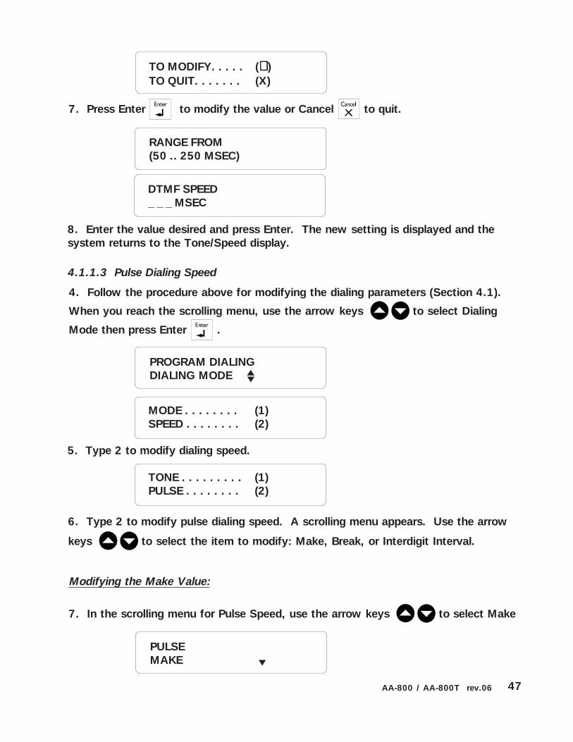
6. Type 2 to modify pulse dialing speed. A scrolling menu appears. Use the arrow
keys to select the item to modify: Make, Break, or Interdigit Interval.
8. Enter the value desired and press Enter. The new setting is displayed and thesystem returns to the Tone/Speed display.
RANGE FROM(50 .. 250 MSEC)
DTMF SPEED_ _ _ MSEC
7. Press Enter to modify the value or Cancel to quit.
4. Follow the procedure above for modifying the dialing parameters (Section 4.1).
When you reach the scrolling menu, use the arrow keys to select Dialing
Mode then press Enter .
PROGRAM DIALINGDIALING MODE
4.1.1.3 Pulse Dialing Speed
5. Type 2 to modify dialing speed.
TONE . . . . . . . . . (1)PULSE . . . . . . . . (2)
MODE . . . . . . . . (1)SPEED . . . . . . . . (2)
TO MODIFY. . . . . (↵↵↵↵↵ )TO QUIT. . . . . . . (X)
Modifying the Make Value:
PULSEMAKE
7. In the scrolling menu for Pulse Speed, use the arrow keys to select Make

48 AA-800 / AA-800T rev.06
RANGE FROM(10 .. 100 MSEC)
9. Press Enter to modify the value or Cancel to quit.
RANGE FROM(10 .. 100 MSEC)
MAKE_ _ _ MSEC
8. Press the Enter key at Make; the current parameter setting is displayed.
10. Enter the value desired and press Enter. The new setting is displayed and thesystem returns to the Pusle Speed scrolling menu.
Modifying the Break Value:
7. In the scrolling menu for Pulse Speed, use the arrow keys to select Break
8. Press the Enter key at Break; the current parameter setting is displayed.
PULSEBREAK
PULSE SPEEDMAKE: 63MSEC
9. Press Enter to modify the value or Cancel to quit.
TO MODIFY. . . . . (↵↵↵↵↵ )TO QUIT. . . . . . . (X)
PULSE SPEEDBREAK: 50 MSEC
TO MODIFY. . . . . (↵↵↵↵↵ )TO QUIT. . . . . . . (X)

49AA-800 / AA-800T rev.06
10. Enter the value desired and press Enter. The new setting is displayed and thesystem returns to Pulse Speed scrolling menu.
RANGE FROM(0.6 .. 3 SEC)
INTERDIGIT_ _ _ SEC
BREAK_ _ _ MSEC
10. Enter the value desired and press Enter. The new setting is displayed and thesystem returns to Pulse Speed scrolling menu.
Modifying the Interdigit Interval:
7. In the scrolling menu for Pulse Speed, use the arrow keys to selectInterdigit
PULSEINTERDIGIT
8. Press the Enter key at Interdigit; the current parameter setting is displayed.
PULSE SPEEDINTERDIGIT: 0.8 SEC
9. Press Enter to modify the value or Cancel to quit.
TO MODIFY. . . . . (↵↵↵↵↵ )TO QUIT. . . . . . . (X)

50 AA-800 / AA-800T rev.06
4.1.2 Line Seizure
Definition: This parameter is used to activate or deactivate line seizure if your systemhas been wired for line seizure (see section 1.3.4). If this feature is not activated, lineseizure will not function even if the proper wiring connections have been made.
Setting:
5. Press Enter . The current parameter setting is displayed.
4. Follow the procedure above for modifying the dialing parameters (Section 4.1).
When you reach the scrolling menu, use the arrow keys to select Line Seizure.
PROGRAM DIALINGLINE SEIZURE
7. Type 1 to enable line seizure, or 2 to disable line seizure. The new setting is dis-played and the system returns to Program Dialing scrolling menu.
LINE SEIZURESTATUS: ENABLE
6. Press Enter to modify the value or Cancel to quit.
ENABLE. . . . . . . . (1)DISABLE. . . . . . . (2)
TO MODIFY. . . . . (↵↵↵↵↵ )TO QUIT. . . . . . . (X)

51AA-800 / AA-800T rev.06
7. Enter the value desired and press Enter. The new setting is displayed and thesystem returns to the Program Dialing scrolling menu.
RANGE FROM(1 .. 7 CALLS)
# OF CALL REPS._ CALLS
Setting:
4.1.3 Call Repetitions
Definition: When an alarm is validated, the system starts calling the phone numbersstored in memory to deliver the alarm message. The Call Repetitions value deter-mines the number of times this procedure is accomplished within one alarm dialoutsequence. The value ranges from 1 to 7 times. The default is 7.
5. Press Enter . The current parameter setting is displayed.
4. Follow the procedure above for modifying the dialing parameters (Section 4.1).
When you reach the scrolling menu, use the arrow keys to select #of Call
Repetitions.
6. Press Enter to modify the value or Cancel to quit.
PROGRAM DIALING# OF CALL REPS.
# OF CALL REPS.6 CALLS
TO MODIFY. . . . . (↵↵↵↵↵ )TO QUIT. . . . . . . (X)

52 AA-800 / AA-800T rev.06
7. Enter the value desired and press Enter. The new setting is displayed and thesystem returns to the Program Dialing scrolling menu.
MESSAGE REPEATS_ _ TIMES
RANGE FROM(2 .. 15 TIMES)
5. Press Enter at Message Repetitions. The current parameter setting is displayed.
4.1.4 Message Repetitions
Definition: The number of times a voice message is delivered by the system when analarm condition is reported. This applies to the messages given over the phone and onthe unit speaker. The value ranges from 2 to 15 times. The default is 3.
Setting:
4. Follow the procedure above for modifying the dialing parameters (Section 4.1).
When you reach the scrolling menu, use the arrow keys to select Message
Repeats.
6. Press Enter to modify the value or Cancel to quit.
MESSAGE REPEATS3 TIMES
TO MODIFY. . . . . (↵↵↵↵↵ )TO QUIT. . . . . . . (X)
PROGRAM DIALINGMESSAGE REPEATS

53AA-800 / AA-800T rev.06
7. Enter the value desired and press Enter. The new setting is displayed and thesystem returns to the Program Dialing scrolling menu.
BUSY TRIES_ TIMES
5. Press Enter . The current parameter setting is displayed.
4. Follow the procedure above for modifying the dialing parameters (Section 4.1).When you reach the scrolling menu, use the arrow keys to select Busy LineTries.
4.1.5 Busy Line Tries
Definition: The number of times a phone number is called when the line is busy. Thisparameter applies equally to all the phone numbers in the dialout sequence. The valueranges from 0 to 3 tries. The default is 1 try. When a line is busy and Busy Line Triesis greater than zero, the busy number is placed at the end of the dialout sequence.
Once all the other numbers have been dialed, the system returns to the busy numbersand tries again, etc. If the number is reached before all the tries defined in Busy LineTries have been done, it is not redialed.
Note: If you have not configured the phone hookup to provide line seizure capabilityand someone is using the phone when the dialout sequence is launched, the systemcounts this as a try, as if all the phone numbers in the dialout sequence were busy. Ifthe Busy Line Tries parameter is set to zero, no other tries will be made in this caseand the alarms that set off the dialout sequence will automatically be acknowledged.
Setting:
6. Press Enter to modify the value or Cancel to quit.
BUSY TRIES1 TIME
RANGE FROM(0 .. 3 TIMES)
TO MODIFY. . . . . (↵↵↵↵↵ )TO QUIT. . . . . . . (X)
PROGRAM DIALINGBUSY TRIES

54 AA-800 / AA-800T rev.06
4.1.6 Tone Delay
Waiting Time for Dial Tone: This is the time the system waits after hooking up to aline before dialing a number. This ensures that the line is ready before dialing (seeFigure 13 below). The system can be set to wait from 1 to 15 seconds after hookup.The default is 4 seconds.
5. Press Enter at Tone Delay. The system prompts for the waiting time.
PROGRAM DIALINGTONE DELAY
Setting:
4. Follow the procedure above for modifying the dialing parameters (Section 4.1).
When you reach the scrolling menu, use the arrow keys to select Tone Delay.
Figure 13: Waiting Time
ON-HOOK
OFF-HOOK
DIAL TONE
WAITING TIME
WAITING TIME FORDIAL TONE: 4 SEC
TO MODIFY. . . . . (↵↵↵↵↵ )TO QUIT. . . . . . . (X)
WAITING TIME FORDIAL TONE: _ _ SEC
RANGE FROM(1 .. 15 SEC)
6. Press Enter to modify the value or Cancel to quit.
7. Enter the value desired and press Enter. The new parameter setting is displayedand the system returns to Program Dialing scrolling menu.

55AA-800 / AA-800T rev.06
7. Enter the value desired and press Enter. The new setting is displayed and thesystem returns to the Program Dialing scrolling menu.
PAUSE DELAY KEY_ _ _ SEC
RANGE FROM(1 .. 255 SEC)
4.1.7 Pause Delay Key
Definition: This parameter is associated with the Pause key . This key is used to
introduce a pause in a telephone number when dialing. The Pause Delay is the length
of the pause. For example, if you need to exit a local phone network before reaching
an outside line, you can use the Pause key after entering the access code (usually ‘9’
—see Section 4.2). The range is from 1 to 255 seconds. The default is 4 seconds.
5. Press Enter . The current parameter setting is displayed.
Setting:
PAUSE DELAY KEY4 SEC
6. Press Enter to modify the value or Cancel to quit.
TO MODIFY. . . . . (↵↵↵↵↵ )TO QUIT. . . . . . . (X)
4. Follow the procedure above for modifying the dialing parameters (Section 4.1).
When you reach the scrolling menu, use the arrow keys to select Pause
Delay.
PROGRAM DIALINGPAUSE DELAY KEY

56 AA-800 / AA-800T rev.06
4.1.8 Call Start Delay
Definition: The time between the validation of an alarm and the beginning of thedialout sequence. A zero value means the dialout sequence begins immediately afteran alarm validation. When an alarm is validated, a message is delivered on-sitethrough the speaker on the front panel and the siren is sounded if it is enabled for thezone in alarm. Call Start Delay allows someone on-site to acknowledge an alarmbefore the dialout sequence is launched. Note that if MUTE is enabled, no message isdelivered on-site before dialout. The value ranges from 0 to 59 minutes. The default is1 minute.
Setting:
4. Follow the procedure above for modifying the dialing parameters (Section 4.1).
When you reach the scrolling menu, use the arrow keys to select Call Start
Delay.
5. Press Enter . The current parameter setting is displayed.
TO MODIFY. . . . . (↵↵↵↵↵ )TO QUIT. . . . . . . (X)
CALL START DLY1 MIN
6. Press Enter to modify the value or Cancel to quit.
CALL START DLY_ _ MIN
7. Enter the value desired and press Enter. The new setting is displayed and the
system returns to the Program Dialing scrolling menu.
PROGRAM DIALINGCALL START DLY
RANGE FROM(0 .. 59 MIN)

57AA-800 / AA-800T rev.06
4.1.9 Time Between Calls
Definition: The delay after a phone number has been called, before proceeding withthe next number in the dialout sequence. If someone who has received a voice mes-sage is unable to acknowledge the alarm at the time of the call, this delay will allowtime to stop the dialout sequence between calls. For example, when the alarm mes-sage is received on a pager or beeper, the user may need more time to phone backand acknowledge. If the system is continuously dialing out, no calls can be made tothe system to acknowledge an alarm. A time delay between calls that is greater thanzero makes this possible. The value ranges from 0 to 59 minutes. The default is 1minute.
4. Follow the procedure above for modifying the dialing parameters (Section 4.1).
When you reach the scrolling menu, use the arrow keys to select Between
Call Time.
5. Press Enter . The current parameter setting is displayed.
BETWEEN CALL TIME1 MIN
TO MODIFY. . . . . (↵↵↵↵↵ )TO QUIT. . . . . . . (X)
6. Press Enter to modify the value or Cancel to quit.
BETWEEN CALL TM_ _ MIN
RANGE FROM(0 .. 59 MIN)
7. Enter the value desired and press Enter. The new setting is displayed and thesystem returns to the Program Dialing scrolling menu.
PROGRAM DIALINGBETWEEN CALL TM

58 AA-800 / AA-800T rev.06
4.1.10 Alarm Recall Time
Definition: This parameter is used to relaunch the dialout sequence when an alarmhas been acknowledged but has not been reset. Alarm recall time is the length oftime between the time the alarm is acknowledged and the time the dialout sequenceis relaunched (as long as the zone has not returned to its normal state for the durationof reset time). If the alarm is reset before the alarm recall time has elapsed, theplanned dialout sequence is cancelled. This parameter ranges from 0 to 12 hours, 59minutes. The default value is 30 minutes.
Setting:
4. Follow the procedure above for modifying the dialing parameters (Section 4.1).
When you reach the scrolling menu, use the arrow keys to select Alarm
Recall Time.
5. Press Enter . The current parameter setting is displayed.
TO MODIFY. . . . . (↵↵↵↵↵ )TO QUIT. . . . . . . (X)
6. Press Enter to modify the value or Cancel to quit.
7. Enter the value desired and press Enter. The new setting is displayed and thesystem returns to the Program Dialing scrolling menu.
ALARM RECALL TM_ _ : _ _ (HR:MIN)
RANGE FROM(0 .. 12HR, 59 .. MIN)
ALARM RECALL TM00 HR, 30 MIN
PROGRAM DIALINGALARM RECALL TM

59AA-800 / AA-800T rev.06
4.1.11 Restore Calls
Definition: This feature launches the dialout sequence when a zone in alarm returnsto its normal state to advise of the change. It can be enabled or disabled and thedefault setting is DISABLED.
4. Follow the procedure above for modifying the dialing parameters (Section 4.1).
When you reach the scrolling menu, use the arrow keys to select Restore
Calls.PROGRAM DIALINGRESTORE CALLS
RESTORE CALLSSTATUS : DISABLE
TO MODIFY. . . . . (↵↵↵↵↵ )TO QUIT. . . . . . . (X)
5. Press Enter . The current parameter setting is displayed.
6. Press Enter to modify the value or Cancel to quit.
ENABLE . . . . . . . (1)DISABLE . . . . . . (2)
7. Type 1 to enable restore calls, or 2 to disable restore calls. The new setting isdisplayed and the system returns to Program Dialing scrolling menu.

60 AA-800 / AA-800T rev.06
4.1.12 Disable the Dialer
Definition: This function allows to disable the dialing sequence in specified zones. Thedialout sequence will not be launched when an alarm occurs in a zone that has adisabled dialer. By default, the dialer is enabled on all zones.
4. Follow the procedure above for modifying the dialing parameters (Section 4.1).
When you reach the scrolling menu, use the arrow keys to select Dialer
Disabled.
5. Press Enter . The zones without dialer are displayed.
NO DIALER ZONE #4
6. Press Enter to ADD a zone on which the dialer will be disabled. Press thedown-arrow key to remove a zone from the dialer-disabled list.
7. Press Enter to ADD a zone on which the dialer will be disabled. Press thedown-arrow key to remove a zone from the dialer-disabled list.
SELECT ZONE(1 . . 8) : _
8. Select the zone on which the dialer must be disabled then press Enter . Thenew setting is displayed and the system returns to Dialer Disabled menu.
PROGRAM DIALINGDIALER DISABLED
DIALER DISABLEDADD ZONE

61AA-800 / AA-800T rev.06
4. Type the phone number. Up to 20 digits can be entered. If you press the Enter key
without entering any digits, the current phone number is erased from memory and the
message PHONE NUMBER DELETED is displayed. Special characters are available for
use with tone dialing: use the Asterisk (*) or Pound (#) Trouble
keys to enter these
characters in a phone number. Each one of these characters counts as one digit in the
number. Press the Pause key to enter a pause in the dialing. This is useful when
an access code is needed to reach an outside telephone line. For example if you dial
“9” to access the telephone lines and wait 4 seconds before dialing the number, you
can use the Pause key feature. Set the Pause Delay parameter to the smallest value
needed for dialing pauses, for example 1 second. In the phone number definition,
SELECT PHONENUMBER (1 .. 8): _
3. Type the number of the phone number to modify and press Enter. The current
value for this phone number is displayed.
ENTER PHONE #n
2. Press Enter to modify.
4.2 PHONE NUMBERS
Definition: Phone numbers are used to report alarm conditions. Various methods areavailable: voice messages, paging and beeper calls. Each number can contain up to20 digits. A maximum of 8 phone numbers can be stored by the system. The order ofthe numbers stored in memory defines the dialout sequence used when an alarm isvalidated, i.e. the first number stored is the first number called in an alarm.
Setting:
1. Press the Phone numbers key Phone
numbers. The numbers currently stored in memory are
displayed along with their parameter definitions. To stop the display and enter pro-
gramming mode, press the Cancel key .
TO MODIFY. . . . . (↵↵↵↵↵ )TO QUIT. . . . . . . (X)

62 AA-800 / AA-800T rev.06
AAAA: is the four-digit code describing the type of alarm.
SS: is the two-digit code of the site where the alarm occurred.
1: is a place-holder
1SS - AAAA
press the pause key as many times as needed for the length of the pause. For
example, 9 - Pause - Pause - Pause - 1234567 will wait three seconds before dialing
the seven-digit number (note that the Pause key is displayed as P on the screen).
5. Once all the digits have been entered, press Enter. The new phone number is
displayed. The system then prompts for the type of system associated with the number.
The possible types are presented in a scrolling menu. Use the arrow keys to
select the type and press Enter.
Home: When this type of number is called, the system delivers a voice messagedescribing the alarm condition to a home telephone. Press Enter to select this option.The system prompts for another phone number. If you are finished, press Cancel.
Cellular: When this type of number is called, the system delivers a voice messagedescribing the alarm condition to a cellular telephone. Press Enter to select this op-tion. The system prompts for another phone number. If you are finished, press Can-cel.
Beeper: This type of number is used with beeper systems. When the number isdialed, the beeper unit simply beeps. Press Enter to select this option. The systemprompts for another phone number. If you are finished, press Cancel.
Pager: This type of number is used to access a numeric pager system. When a pagerdevice is paged, a code number is displayed on the pager screen. The Agri-Alert usesthis number to transmit information to the user. The code is in the form of a tele-phone number and contains the following information:
PHONE NUMBER OFHOME?

63AA-800 / AA-800T rev.06
Table 2: Pager Codes Used by the Agri-Alert System
101 - 3000
102 - 3000Site 02
Site 01
Number displayed on the pager device
SS is the site where the Agri-Alert is installed. AAAA is an alarm code generated bythe Agri-Alert. The site number is defined by the user. For example, if two Agri-Alerts are installed on separate sites, the user can identify each site with a uniquecode number. In the example below, alarm code 3000 is used as a test code.
Table 2 below defines the codes used. RESTORE ZONE means the zone returns to itsnormal state.
+#*<. <,!,/
=33&433&&33& =4&,+D/*
=3344334&334 =4&,+D*+"*
333: "
/8+*.*,-+#,
&33= 9*8;+
433= *-!0#$%&
>33= #0,*!"
%33= #0-.-+#$4&
=33= 8-+*/"9"
?33= 98,"+-/"9"
*+"*/8+*.
&33? 2+9*8
433? 2+#$%&
>33? 2+,*!"
%33? 2+#$4&

64 AA-800 / AA-800T rev.06
DELAY FOR PAGER(0 .. 59 SEC): _ _
9. Enter the total delay (Message Delay) used to wait for the end of the pager mes-sage and press Enter. The system prompts for another phone number. If you arefinished, press Cancel.
ENTER CODE TOPAGE (0 .. 99): _ _
6. To configure a phone number as a pager number, use the arrow keys to scroll tothe Pager item in the menu:
7. Press Enter to select this option.
PHONE NUMBER OFPAGER?
8. Enter the two digit code used to identify the site and press Enter.
Figure 14: Calling a Pager Number
Figure 14 below shows the sequence of events. The Agri-Alert first dials the numberof the pager device. When the pager system responds, the Agri-Alert waits for thevoice message from the pager system to finish. In the diagram, this is called themessage delay. The diagram shows an additional delay used to ensure that the pagersystem is ready to receive the code number from the Agri-Alert system. This is up tothe system (usually 3 seconds). Following this, the Agri-Alert dials the seven digitcode number or numbers to be displayed on the pager device. When configuring anumber as a pager number, the user enters the value: Message Delay when thesystem prompts for the Delay for Pager.
ADDITIONALDELAY
DIALINGPAGERNUMBER
DIALINGCODENUMBER
MESSAGEDELAY
TimePAGER SYSTEM ANSWERS AGRI-ALERT TRANSMITSAGRI-ALERT DIALS

65AA-800 / AA-800T rev.06
4.3 ON SITE LISTENING
Definition: This feature allows the user to listen to on-site sounds during a statusreport or an alarm report. The integrated microphone on the control panel is used forthis purpose. The user can enable or disable on-site listening and adjust the listeningtime. The default setting is DISABLED with a listening time of 30 seconds.
Setting:
1. Press the On-site Listening key PRSOn-site
Listening. The status (Enabled/Disabled) is displayed,
followed by the current listening time.
2. Press Enter to modify or Cancel to quit.
RANGE FROM(0 .. 59 SEC)
ENTER NEW DELAY_ _ SEC
4. Enter the new delay and press Enter. The system displays the new delay settingand returns to the Date/Time display.
STATUS . . . . . . . (1)DELAY . . . . . . . . (2)
3. Type 1 to modify the current value to the opposite state. The system displays thenew setting and returns to the Date/Time display. Type 2 to modify the delay.
STATUS: ENABLEDELAY: 10 SEC.
TO MODIFY. . . . . (↵↵↵↵↵ )TO QUIT. . . . . . . (X)

66 AA-800 / AA-800T rev.06
4.4 RINGS / ANSWERING MACHINE
Definition: The user can define the number of rings before an incoming call is an-swered, for example for a status report. The values range from 1 to 20 rings. Thesystem can also be configured to connect a telephone answering device on the samephone line. When this feature is enabled, the Agri-Alert system answers incomingcalls only if a special ring sequence is followed. Otherwise, the telephone answeringdevice takes the call after a preset number of rings. The special ring sequence usedto connect to the Agri-Alert system is as follows:
— dial the Agri-Alert phone number and hang-up after one ring— redial the number after 30 seconds have elapsed— after the first ring, the Agri-Alert system will answer the call
If the answering machine is set to answer after one ring, it must be set to more thanone ring for this sequence to work. If an answering machine is not used, any callsmade to the Agri-Alert system are answered after the number of rings defined. Bydefault, the number of rings is set to 8 and the answering machine feature is disabled.
Setting:
1. Press the Ring key Ring
. The current parameter setting is displayed.
2. Press Enter to modify the value or Cancel to quit.
8 RINGS
To Enable / Disable Answering Machine:
3. Type 1 to use an answering machine with the Agri-Alert system. The systemreturns to the Date/Time display.
DO YOU HAVE ANS-WERING MACHINE?
YES . . . . . . . . . . (1)NO . . . . . . . . . . (2)
TO MODIFY. . . . . (↵↵↵↵↵ )TO QUIT. . . . . . . (X)

67AA-800 / AA-800T rev.06
Setting:
4.5 SYSTEM’S VOICE MUTE
Definition: When an alarm condition is validated, an alarm message is immediatelydelivered through the unit speaker. You can turn the speaker on or off. By default,the mute function is disabled and the speaker is turned on.
RANGE FROM(1 .. 20)
ENTER NEW NUMBEROF RINGS: _ _
4. Type the new number of rings and press Enter. The system displays the newvalue and returns to the Date/Time display.
To Set Number of Rings:
3. Type 2 to disable the answering machine feature and set the number of ringsbefore the Agri-Alert system answers a call.
1. Press the System key . The current revision number of the software program
is displayed. The installer password must then be entered.
2. Enter the installer password (0801 by default) and press Enter .
3. Using the up and down-arrow keys , scroll the menu until the item dis-
played is PRORGRAM AUX’S and press Enter .
SOFTWAREREV. x.xxx
ENTER INSTALLERPASSWORD: _ _ _ _
SYSTEMPROGRAM AUX’S
PROGRAM AUX’SSYST.VOICE MUTE

68 AA-800 / AA-800T rev.06
TO MODIFY . . . . (↵↵↵↵↵ )TO QUIT . . . . . . . (X)
SYST.VOICE MUTESTATUS: DISABLE
ENABLE . . . . . . . (1)DISABLE . . . . . . (2)
4. Using the up and down-arrow keys , scroll the menu until the item dis-
played is SYSTEM’S VOICE MUTE and press Enter .
5. The status (Enabled/Disabled) is displayed. Press Enter to modify the status.
6. Type 1 to enable restore calls, or 2 to disable the speaker. The new setting isdisplayed and the system returns to Program Aux’s scrolling menu.

69AA-800 / AA-800T rev.06
NOITCA ESNOPSER SRETEMARAP
SIMRALANA.1.DETCETED
despaleemitehtserusaemmetsysehTlitnumralaehtfonoitcetedehtecnis
emiTnoitingoceR .dehcaersiemiTnoitingoceR
SIMRALANA.2.DETADILAV
nehW emiTnoitingoceR A,despalesahotetis-nodereviledsiegassemeciov
.)delbanesiETUMsselnu(mralaehttroperdespaleemitehtserusaemmetsysehT
litnunoitadilavecnis yaleDtratSllaC siehtotdetcennocsinerisafI.dehcaer
.detavitcasiti,tuptuoneris
etuMyaleDtratSllaC
TUOLAID.3.SNIGEB
nehW yaleDtratSllaC hcae,despalesahsiecneuqestuolaidehtnirebmunenohp
ybdetarapessillachcae;dellac emiT.yaledsllacneewteb yranidronasisihtfI
egassemeciova,rebmunralullecroenohpehtsemitforebmunehT.dereviledsi
eulavehtnosdnepeddereviledsiegassemfo .snoititepeRegasseM etumehtfI
oslasiegassemsiht,delbasidsinoitcnufna,rebmunregaparoF.etis-nodereviled
.metsysregapehtottnessiedocmralasitinurepeebeht,rebmunrepeebaroFehttadecalperasrebmunysuB.dellac
delaiderdnaecneuqestuolaidehtfodneotgnidrocca seirTysuB seunitnoctuolaiD.
ro,degdelwonkcasimralaehtrehtielitnudetucexeneebsahecneuqestuolaideht
foeulavehtotgnidrocca llaCfo#.snoititepeR
sllaCneewteBemiTsnoititepeRegasseM
seirTysuBsnoititepeRllaCfo#
noitceteDenoTlaiDyeKyaleDesuaP
deepSlaiD
SIMRALA.4.DEGDELWONKCA
sinerisafI.deppotssiecneuqestuolaiDsiti,tuptuonerisehtotdetcennoc
degdelwonkcasawmralaehtfI.deppotsfidnaenohpehtrevo gninetsiLetiSnO si
etis-nootnetsilnacresueht,delbanerofdenifedyaledehtotgnidroccasdnuos
.gninetsiletis-no
gninetsiLetiSnO
CHAPTER FIVE: ALARM PARAMETERS
5.1 ALARM VALIDATION: SUMMARY OF EVENTS

70 AA-800 / AA-800T rev.06
SYSTEMPROGRAM AUX’S
5.2.1 Backup Battery Voltage Readout
See Appendix C for normal battery life spans.
5.2 SYSTEM ALARMS
Definition: The Agri-Alert system detects certain internal alarm conditions that be-have in the same way as a zone alarm, i.e. the siren is activated, the dialout sequenceis launched, etc. These alarms have a fixed recognition time of 2 minutes and a resettime of 45 minutes if no one is present or 2 minutes is someone is present ( i.e. thedisplay backlight is turned on – the reset time for low battery and system troublealarms is always 45 minutes). The table below describes these alarms:
Table 3: System Alarms
EPYTMRALA GNINAEM
YRETTABWOLSSELSIEGATLOVYRETTAB
NAHTEROMROFV5.01NAHT.NIM2
TCEFEDNERIS/NWOLB8FESUFNERIS
NERIS/ELBUORTERIWNERISNOITCNUFLAM
TCEFEDTUPTUOCDV21)ylnosledomT008no(
NWOLB4FESUF
ELBUORTMETSYSENOZNOELBUORTGNIRIW
METSYSROSTUPNINOITCNUFLAM
1. Press the System key . The current revision number of the software program
is displayed. The installer password must then be entered.
2. Enter the installer password (0801 by default) and press Enter .
SOFTWAREREV. x.xxx
ENTER INSTALLERPASSWORD: _ _ _ _

71AA-800 / AA-800T rev.06
BACKUP BATTERY12.3 V
PROGRAM AUX’SBACKUP BATTERY
3. Using the up and down-arrow keys , scroll the menu until the item dis-
played is PRORGRAM AUX’S and press Enter .
4. Using the up and down-arrow keys , scroll the menu until the item dis-
played is BACKUP BATTERY and press Enter .
5. If the voltage is less than 10.5 volts, the system displays the warning “LO BAT-
TERY” before displaying the current voltage. The system returns to the Program
Aux’s scrolling menu.

72 AA-800 / AA-800T rev.06
5.3 OUTDOOR TEMPERATURE COMPENSATION ON TEMPERATURE ALARMS
The outdoor temperature compensation feature is only available on AA-800T models.
Definition: In situations where the outdoor temperature is high, the room temperaturewill rise as warm air enters the building through ventilation inlets. If the high set pointdefined above is not adjusted to take this into account, a high temperature alarm maybe needlessly set off. To avoid this situation, the system can compensate for highoutdoor temperatures when monitoring temperature alarms. When this feature isactivated and the outdoor temperature is close to the high set point, the room tem-perature is monitored with respect to the outdoor temperature. An alarm is set offonly if the room temperature rises above the outdoor temperature by a certain valuecalled the offset. In addition to this, the system also uses a critical high temperatureas an absolute limit on room temperature. When room temperature reaches the criti-cal high temperature, an alarm is set off. To use this feature, an outdoor temperatureprobe must be connected to a temperature zone. The probe must have a pale-colored(white or grey) PVC casing and should be installed near an air intake.
Critical Temperature: The absolute temperature limit for room temperatures. Whenthe room temperature reaches this point, an alarm is set off, no matter what theoutdoor temperature is.
Offset: In general, the room temperature is greater than the outdoor temperature by acertain number of degrees, called the offset. The offset determines when an alarm isset off. It is the number of degrees the room temperature can rise above the outdoortemperature without setting off an alarm.
The diagram below shows when the outdoor temperature compensation feature takeseffect (if it has been enabled by the user). When the outdoor temperature is greateror equal to the high set point less the offset, the system uses the outdoor temperatureas the reference point for monitoring high temperature alarms.
High Set Point
Outdoor T°
Temperature
Time
Normal AlarmMonitoring
OFFSET
Outdoor T°Compensation
Figure 15: Outdoor Temperature Compensation

73AA-800 / AA-800T rev.06
Figure 16: Critical Temperature Monitoring
In the second case, the system monitors the difference between the room and out-door temperatures. When this difference is greater than the offset, an alarm is setoff.
Figure 17: Monitoring the Indoor-Outdoor Temperature Differences
Critical T°
Room T°
Temperature
Time
Alarm 3Alarm 2Alarm 1ALARM
NO ALARM
When outdoor temperature compensation is in effect, the system monitors (i) theroom temperature with respect to the critical temperature (this check has the highestpriority); (ii) the room temperature with respect to the outdoor temperature. Thefigure below illustrates the first case:
Room T°
Outside T°
Temperature
Time
Alarm 2Alarm 1
OFFSET

74 AA-800 / AA-800T rev.06
To Make an Outdoor Probe Assignment:
1. Press the System key . The current revision number of the software program
is displayed. The installer password must then be entered.
2. Enter the installer password (0801 by default) and press Enter .
3. Using the up and down-arrow keys , scroll the menu until the item dis-
played is PRORGRAM AUX’S and press Enter .
SOFTWAREREV. x.xxx
ENTER INSTALLERPASSWORD: _ _ _ _
SYSTEMPROGRAM AUX’S
4. Using the up and down-arrow keys , scroll the menu until the item dis-
played is OUTSIDE PROBE and press Enter . The message “WARNING! ALARM
MEMORY WILL BE LOST!” is displayed. The system prompts for the outdoor probe zone
number.
5. Enter the zone number of the outdoor probe and press Enter. By default, zone 8 isassigned to the outdoor probe. If a different zone number was previously defined asthe outdoor probe, zone 8 will take the default zone settings. The new probe assign-ment is displayed and the system returns to the Program Aux’s scrolling menu.
SELECT ZONE(1..8): _
PROGRAM AUX’SOUTSIDE PROBE

75AA-800 / AA-800T rev.06
To Activate / Deactivate the Outdoor Temperature Compensation (AA-800T Model Only):
Note: If, when configuring a zone, the zone selected is the outdoor probe used for theoutdoor temperature compensation feature and the compensation feature is currentlyenabled, the system displays the message: DEACTIVATE OUTDOOR STATUS. Use theprocedure described above to deactivate the compensation.
1. Press the Outdoor key. The system displays the current status, outdoor
probe assignment and temperature offset value.
2. Press Enter to modify the outdoor temperature compensation settings or
Cancel to quit. The system displays a menu.
OUTDOORPARAMETERS
STATUSDISABLE
OUTDOOR PROBEZONE #8
OFFSET TEMP.5.0°F
STATUS. . . . . . . . (1)OFFSET TEMP . . . (2)
3. Type 1 to change the status of the outdoor compensation feature.
ENABLE. . . . . . . . (1)DISABLE . . . . . . . (2)
4. Type 1 to enable, or 2 to disable outdoor compensation feature. The new settingis displayed and the system returns to the Date/Time display.
TO MODIFY. . . . . (↵↵↵↵↵ )TO QUIT. . . . . . . (X)

76 AA-800 / AA-800T rev.06
To Set the Offset Temperature (AA-800T Model Only):
RANGE FROM(0°F..36°F)
OFFSET TEMP._ _ _ _ °F
4. Enter the offset temperature and press Enter. The system displays the new set-ting and returns to the Date/Time display.
1. Press the Outdoor key. The system displays the current status, outdoor
probe assignment and temperature offset value.
2. Press Enter to modify the outdoor temperature compensation settings or
Cancel to quit.
STATUS. . . .. . . . (1)OFFSET TEMP . . . (2)
3. Type 2 to change the offset temperature. By default, the offset is 5°F (2.8°C).
OUTDOORPARAMETERS
STATUSDISABLE
OUTDOOR PROBEZONE #8
OFFSET TEMP.5.0°F
TO MODIFY. . . . . (↵↵↵↵↵ )TO QUIT. . . . . . . (X)

77AA-800 / AA-800T rev.06
5.4 ALARM MEMORY
Definition: Each alarm condition detected by the Agri-Alert system is recorded in
memory for future reference. The parameters stored in memory are the zone number,
the alarm type, the time, the date, the user who acknowledged the alarm (if a user is
defined) and the time and date of acknowledgement. The system stores only the last
ten alarms in memory. It should be noted that if the zones are reconfigured at any
time, the alarm memory recorded up to that time is erased.
If the password feature is enabled, the system requires a password before acknowl-
edging an alarm from the keypad (acknowledging over the phone always requires a
password). This password will appear in the alarm memory listing only if the master
password is currently logged onto the system. If a user is logged on, the system will
not identify the password that acknowledged the alarm. If, at the time the alarm was
acknowledged, the password feature was not enabled, the alarm memory listing will
not contain the password that acknowledged the alarm.
To access alarm memory, press the Alarm Memory key. If no alarm events are
presently stored in memory, the system returns the message: NONE. To step to the
next alarm entry while the current entry is still scrolling on the display, press the
Cancel key .
Examples: In the first example, the password of the user that acknowledged thealarm is not identified. This means either no password was entered when the alarmwas acknowledged or the current password is not the master password.
In the second example, the password is identified. This means that a password wasentered when the alarm was acknowledged and the current password is the masterpassword.
ZONE #1HI TEMPERATURE AT 12:47 PM ON AUG 14 2000ACK BY 1234 AT 01:16 PM ON AUG14 2000
SIREN OUTPUTDEFECTED AT 12:47 PM ON AUG 14 2000ACK AT 01:16 PM ON AUG14 2000

78 AA-800 / AA-800T rev.06
5.5 ZONE STATUS DISPLAY
Definition: You can display zone status information at any time by using the Zonekey. This key also allows you to modify certain zone parameters such as set pointswithout having to reconfigure the zone. The current zone definition and data readingsare displayed along with the zone status. The information displayed depends on thetype of zone:
1. Dry contact zones: OPEN / CLOSE, recognition time2. Temperature zones: temperature reading, set points, critical temperature
and recognition time.3. Pulse count zones: pulse count, set points and observation length
When using the outdoor temperature compensation feature, the zone assigned to theoutdoor probe is identified by the message OUTDOOR PROBE (See Section 5.3). Thedifferent zone states are summarized below:
1. DISABLED: When a zone is first configured, it is in disabled state, until theuser activates it using the Activate key. When a zone is disabled, no alarmsare detected on the zone input. The zone LED on the front panel is turned off.
2. ACTIVATED: Alarm detection is enabled on the zone input. The zone LEDon the front panel is turned on. To change the state to BYPASSED, use theBypass/Activate key.
3. BYPASSED: No alarm detection is performed on the zone input. The LED onthe front panel blinks slowly. To change the state to ACTIVATED, use theBypass/Activate key.
5.5.1 Viewing and Modifying Dry Contact Zones
The recognition time of a dry contact zone can be modified using the Zone key asfollows (refer to section 3.2 for further information about dry contact zones and rec-ognition time).
1. Press the Zone key Zone .
SELECT ZONE(1 .. 8): _
2. Enter the number of a dry contact zone. The state of the zone is displayed, fol-lowed by the status.
ZONE # 5OPEN

79AA-800 / AA-800T rev.06
3. Press Enter to modify the recognition time of the dry contact zone.
TO MODIFY. . . . . (↵↵↵↵↵ )TO QUIT. . . . . . . (X)
ZONE # 5STATUS : ACTIVATED
RANGE FROM(0 .. 59 HR, 0.. 59 MIN, 0 .. 59 SEC)
RECOGNITION TIME_ _ : _ _ : _ _
4. Enter the recognition time and press Enter. The system displays the new settingand returns to the Date/Time display.
5.5.2 Viewing and Modifying Temperature Zones
The Zone key allows to modify the set points of temperature zones and their recogni-tion time (refer to section 3.2 for further information about temperature zones andrecognition time).
1. Press the Zone key Zone .
2. Enter the number of a temperature zone. The state of the zone is displayed, fol-lowed by the status.
SELECT ZONE(1 .. 8): _
ZONE # 675.0°F
ZONE # 6STATUS : ACTIVATED
SET POINTSLO: 55.0 oF, HI: 85.0 oF

80 AA-800 / AA-800T rev.06
3. The critical temperature is displayed only if the outdoor temperature compensation
feature is activated (see Section 5.3) (on AA-800T models only). Press Enter to
modify the current set points and/or recognition time or press Cancel to quit.
Modifying Recognition Time
4. Press 1 to modify the recognition time.
5. Enter the recognition time and press Enter. The system displays the new settingand returns to the Date/Time display.
Modifying Temperature Set Points
4. Press 2 to modify the temperature set points.
CRITICAL TEMP.95.0 oF
TO MODIFY. . . . . (↵↵↵↵↵ )TO QUIT. . . . . . . (X)
RECOGNITION . . . (1)SET POINTS . . . . . (2)
RANGE FROM(0 .. 59 HR, 0.. 59 MIN, 0 .. 59 SEC)
RECOGNITION TIME_ _ : _ _ : _ _
TEMPERATURESET POINTS
RANGE FROM(-40.0oF .. 149.0 oF)
LO SET POINT

81AA-800 / AA-800T rev.06
CRITICAL TEMP. _ _ _ _ _ oF
CRITICAL TEMP.
RANGE FROM(XoF .. 149.0 oF)
5. This is the lower value of the normal temperature range. It ranges from -40 oF to
149 oF (-40 oC to 65 oC) with an accuracy of 0.1 oF (0.1 oC). Enter the low set point
and press Enter. To enter a negative value, use the key, either before or after
the digits.
6. This is the upper value of the normal temperature range. It ranges from the low
set point to 149 oF (65 oC) with an accuracy of 0.1 oF (0.1 oC). Enter the high set
point and press Enter. To enter a negative value, use the key, either before or
after the digits. The high set point must be greater than the low set point.
HI SET POINT _ _ _ _ _ oF
LO SET POINT _ _ _ _ _ oF
RANGE FROM(X°F .. 149.0 oF)
HI SET POINT
7. The critical temperature is displayed only if the outdoor temperature compensation
feature is activated (see Section 5.3) (on AA-800T model only). It is the absolute
temperature limit for room temperatures. It is used in conjunction with the outdoor
temperature compensation feature. When the room temperature reaches this point
and the outdoor temperature compensation feature is enabled, an alarm is set off, no

82 AA-800 / AA-800T rev.06
matter what the outdoor temperature is. It ranges from the high set point to 149 oF
(65 oC) with an accuracy of 0.1 oF (0.1 oC). Enter the critical temperature and press
Enter. To enter a negative value, use the key, either before or after the digits.
The system displays the current zone temperature and returns to the Date/Time dis-
play.
5.5.3 Viewing and Modifying Pulse Count Zones
The Zone key allows to modify the lo and hi set points of pulse count zones. It is alsopossible to change the observation length. Refer to section 3.2 for further informationabout pulse count zones.
1. Press the Zone key Zone .
2. Enter the number of a pulse count zone. The state of the zone is displayed, fol-lowed by the status.
3. Press Enter to modify the pulse count zone set point and observation length.
SELECT ZONE(1 .. 8): _
TO MODIFY. . . . . (↵↵↵↵↵ )TO QUIT. . . . . . . (X)
ZONE # 710 PULSES
ZONE # 7STATUS : ACTIVATED
SET POINTSLO:3 PULSES, HI:15 PULSES
OBSERVATION LENGTH00 : 05 : 30
PULSE COUNTPULSE SET POINT
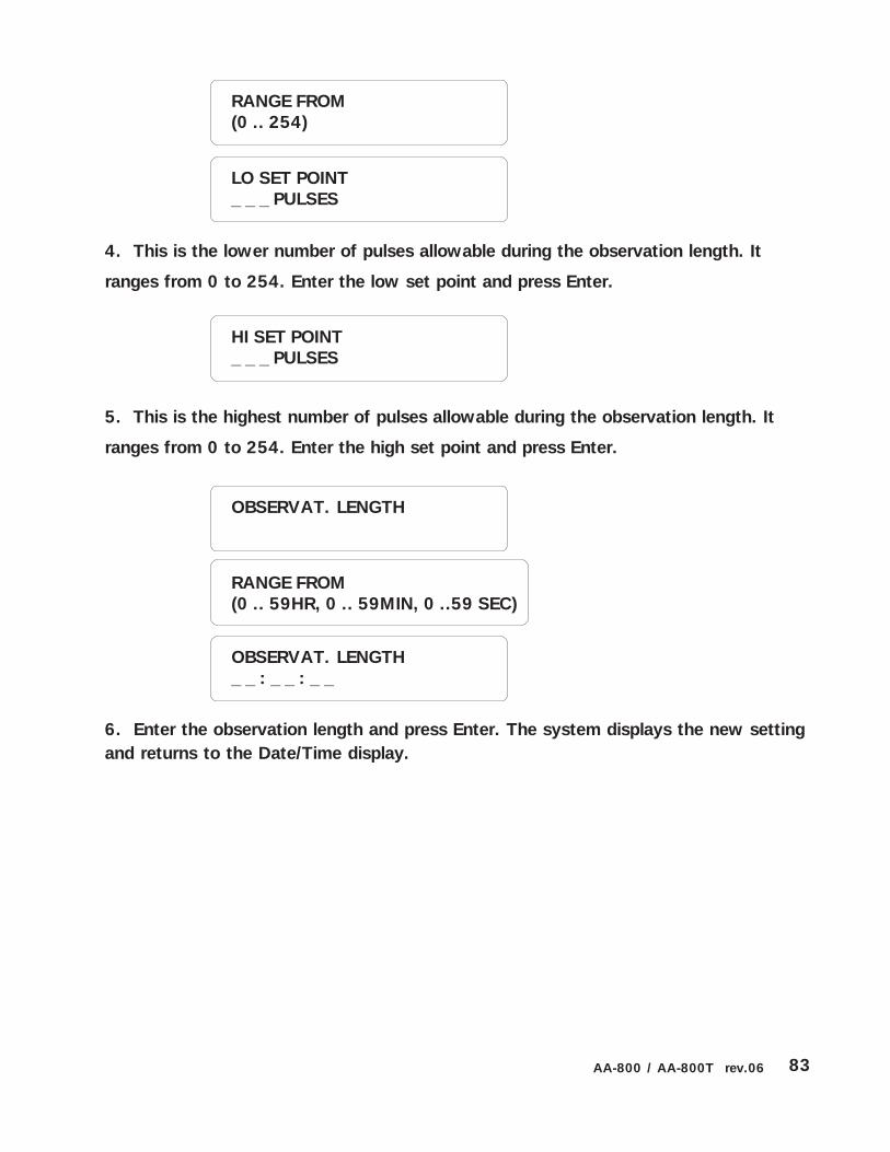
83AA-800 / AA-800T rev.06
RANGE FROM(0 .. 254)
LO SET POINT_ _ _ PULSES
4. This is the lower number of pulses allowable during the observation length. It
ranges from 0 to 254. Enter the low set point and press Enter.
5. This is the highest number of pulses allowable during the observation length. It
ranges from 0 to 254. Enter the high set point and press Enter.
6. Enter the observation length and press Enter. The system displays the new settingand returns to the Date/Time display.
HI SET POINT_ _ _ PULSES
OBSERVAT. LENGTH
OBSERVAT. LENGTH_ _ : _ _ : _ _
RANGE FROM(0 .. 59HR, 0 .. 59MIN, 0 ..59 SEC)

84 AA-800 / AA-800T rev.06
5.6 PARTITIONS
Definition: Zones can be grouped into partitions, relating alarm systems located in thesame area. This makes it easy to activate or bypass several zones at once, if theyare physically located in the same area or if they are logically connected together.Figure 18 below gives an example of this. If, for example, the animals in Building 2are evacuated, the alarm systems for the entire building can be turned off at once.Up to 8 different partitions can be programmed into the system. If changes are madeto a partition, all zones associated with the partition are deactivated. Note that bur-glar zones cannot be included in a partition. If a zone belonging to a partition is rede-fined as a burglar zone, it will be removed from the partition.
Setting:
1. Press the Partitions key . The partitions currently stored in memory are dis-
played. To stop the display, press the Cancel key .
Figure 18: Example of Partitioning
2. Press Enter to modify.
ENTER PARTITION(1 .. 8): _
3. Type the number of the partition to modify and press Enter.
TO MODIFY. . . . . (↵↵↵↵↵ )TO QUIT. . . . . . . (X)
Partition 2Agri-Alert800T / 800
Temperature Sensors
Partition 1
ROOM 1 ROOM 2
ROOM 3 ROOM 4
BUILDING 2
BUILDING 1
ZONE 2 ZONE 3
ZONE 4
ZONE 5
ZONE 1

85AA-800 / AA-800T rev.06
PARTITION #1ZONE #1, 2, 3
3. The different options are presented in a scrolling menu. Use the up and down arrow
keys to select ADD ZONE and press Enter.
Adding a zone:
4. The zones currently included in the partition are displayed on the first line. Enterthe number of the zone to add to the partition and press Enter. If you choose a zonethat is already assigned to another partition, the system responds with the message:ZONE IS ALREADY SELECTED. The system displays the new partition definition.
#1) 1, 2, 3ADD ZONE: _
PARTITION #1ZONE #1, 2, 3, 4
Deleting a zone:
PARTITION #1DEL ZONE?
3. The different options are presented in a scrolling menu. Use the up and down arrow
keys to select DEL ZONE and press Enter.
#1) 1, 2, 3, 4DEL ZONE: _ _
4. Enter the number of the zone to delete from the partition and press Enter. Thesystem displays the new partition definition.
PARTITION #1ADD ZONE?

86 AA-800 / AA-800T rev.06
5.7 BYPASS / ACTIVATE FUNCTION
Definition: The Agri-Alert system can activate or bypass individual zones and parti-tions. When a zone is bypassed, no alarm detection is performed on the zone input.When a zone becomes active, the corresponding LED on the left hand side of the frontpanel turns on and the system monitors the alarm input connected to the zone. Whenan alarm occurs, the LED for the zone where an alarm was detected starts blinkingrapidly. The relevant data are recorded in alarm memory and the dialout sequence islaunched. Note that burglar zones cannot be activated in this way although they canbe bypassed one zone at a time. These zones are activated with the dot key and apassword.
Setting:
Type 1 to make more changes. Type 2 to exit this function; the system returns tothe Date/Time display.
Deleting a partition:
3. The different options are presented in a scrolling menu. Use the up and down
arrow keys to select DEL PARTITION and press Enter. The system displays
the message PARTITION DELETED.
PARTITION #1DEL PARTITION ?
After making a change:
The system prompts to make more changes or to end the session:
TO CONTINUE. . . .(1)TO END . . . . . . . . (2)

87AA-800 / AA-800T rev.06
1. Press the Bypass / Activate key.
ZONE . . . . . . . . . (1)PARTITION . . . . . (2)
2. Type 1 to change the status of a zone;
ENTER ZONE(1 .. 8): _
To change the status of a zone:
3. Type the number of the zone and press Enter. If the zone is not properly config-ured, the system responds with the message: INCOMPLETE DATA.
4. Type 1 to activate, or 2 to bypass the zone. The new state of the zone is dis-played. If you have just activated a zone, the LED associated with the zone will turnon.
To change the status of a partition:
1. Press the Bypass / Activate key.
ZONE . . . . . . . . . (1)PARTITION . . . . . (2)
2. Type 2 to change the status of a partition.
ENTER PARTITION(1 .. 8): _
3. Type the number of the partition and press Enter. If the partition does not exist,the system responds with the message: PARTITION NONE.
ACTIVATE . . . . . . .(1)BYPASS . . . . . . . . (2)
ACTIVATE . . . . . . (1)BYPASS . . . . . . . . (2)
4. Type 1 to activate or 2 to bypass the partition. The new state of the zone isdisplayed. If you have activated a partition, all the LEDs associated with the zones inthe partition turn on.

88 AA-800 / AA-800T rev.06
5.8 ENTRY DELAY
Definition: The time needed to disarm the burglar zones when entering the site beforean alarm is set off. This applies to all burglar zones and ranges from 0 to 5 minutes, 0to 59 seconds. The default is 30 seconds. The entry delay countdown begins whenan alarm is detected in a burglar zone with an entry delay.
Setting:
1. Press the Entry/Exit Delay key Entry/ExitDelay
.
2. Type 1 to adjust the entry delay.
ENTRY DELAY. . . . . .(1)EXIT DELAY . . . . . . . (2)
ENTRY DELAY0 MIN, 30 SEC
3. Press Enter to adjust the entry delay or Cancel to quit.
4. Enter the new delay and press Enter. The system displays the new setting andreturns to the Date/Time display.
RANGE FROM(0 .. 5 MIN, 0 .. 59 SEC)
ENTER NEW DELAY_ MIN : _ _ SEC
TO MODIFY. . . . . (↵↵↵↵↵ )TO QUIT. . . . . . . (X)

89AA-800 / AA-800T rev.06
5.9 EXIT DELAY
Definition: The time needed to exit the site before the system starts monitoring thealarm inputs. This applies only to burglar zone and is common to all zones. It rangesfrom 0 to 5 minutes, 0 to 59 seconds. The default is 30 seconds.
Setting:
1. Press the Entry/Exit Delay key Entry/ExitDelay
.
2. Type 2 to adjust the exit delay.
EXIT DELAY0 MIN, 30 SEC
3. Press Enter to adjust the exit delay or Cancel to quit.
4. Enter the new delay and press Enter. The system displays the new setting andreturns to the Date/Time display.
RANGE FROM(0 .. 5 MIN, 0 .. 59 SEC)
ENTER NEW DELAY_ MIN : _ _ SEC
ENTRY DELAY. . . . . . (1)EXIT DELAY . . . . . . . (2)
TO MODIFY. . . . . (↵↵↵↵↵ )TO QUIT. . . . . . . (X)

90 AA-800 / AA-800T rev.06
5.10 SIREN DELAY
Definition: When an alarm condition is detected, and if the siren is enabled for thezone in alarm, the system activates the siren. This parameter defines the time thesiren will sound. The value ranges from 1 to 20 minutes. The default is 5 minutes.
Setting:
1. Press the Siren Delay key Siren delay
. The current siren delay is displayed.
5 MIN
RANGE FROM(1 .. 20 MIN)
ENTER NEW DELAY_ _ MIN
2. Press Enter .
3. Enter the new delay and press Enter. The system returns to the Date/Time display.
TO MODIFY. . . . . (↵↵↵↵↵ )TO QUIT. . . . . . . (X)

91AA-800 / AA-800T rev.06
TROUBLESHOOTING GUIDE
MELBORP SNOITULOS
.nosnrutsyawlaDELMRALAehT .nwolbsiesufhcihwenimretedotyromeMmralAkcehC-1tnemecalperrofAxidneppAnielbatehtotrefeR
ehtwollof,esufnerisehthtiwsimelborpehtfI.snoitacificeps:wolebspets
enimretedotyrt,nwolbsiesuffI.)8F(esufnerisehtkcehC-2siht-yticapacesufesaercnitonoD.gnicalpererofebyhw54siemitteserehttahtrebmemeR.drazaherifaebdluoc
sienoemosfisetunim2dnatneserpsienoonfisetunim.tneserp
rotsisera,slanimretnerisehtotdetcennocsinerisonfI-3ehteeS.)W½,k5.1(ecalpstinidetcennocebtsum
.)1.3.3.1noitces(launamnoitallatni
W½,k5.1adda,hgihotsiecnadnepminerisehtfI-4.elbissopsanerisehtotesolcsa,tiurcicnerisehtotrotsiser
.evitcefedebyamnerisroeriwnerisehT-5
.relaedruoytcatnoc,stsisrepmelborpehtfI-6
.nosnrutDELELBUORTehT ehtxiF.noitamrofnieromrofyekELBUORTehtsserP-1teserotunemehtniESAREesoohcdnaelbissopfimelborp
.galfelbuorteht
.relaedruoytcatnoc,stsisrepmelborpehtfI-2
nosnrutDELERULIAFCAV61ehT.KOsirewoplacirtceledna
enimretedotyrt,nwolbsiesuffI.7Fdna6FsesufkcehC-1siht-yticapacesufesaercnitonoD.gnicalpererofebyhw
.drazaherifaebdluoc
.gniriwdnaremrofsnartllawehtkcehC-2
tupniCAV61ehttaegatlovkcehcotretemtlovaesU-3.)muminimCAV61(slanimret
.relaedruoytcatnoc,stsisrepmelborpehtfI-4
ΩΩΩΩΩ
ΩΩΩΩΩ

92 AA-800 / AA-800T rev.06
MELBORP SNOITULOS
nosnrutDELYRETTABWOLehT.KOsirewoplacirtceledna
siretnuoceht;setunim54siemitteserehttahtrebmemeR-1.ffosnrutthgilkcabyalpsidehtecnoylnodetrats
gnitcelesdnayekmetsySehtgnisserpybegatlovyrettabkcehC-2egatlovlamroN.unems'xuAmargorPehtmorfYRETTABPUKCAB
.V41otV21morfdaerdluohs
erofebyhwenimretedotyrt,nwolbsiesuffI.82FesufkcehC-3erifaebdluocsiht-yticapacesufesaercnitonoD.gnicalper
.drazah
.gniriwdnaremrofsnartllawehtkcehC-4
slanimrettupniCAV61ehttaegatlovkcehcotretemtlovaesU-5.)muminimCAV61(
.yrettabehtotgniriwehtkcehC-5
.relaedruoytcatnoc,stsisrepmelborpehtfI-6
ybedomybdnatSotniseogmetsyS.flesti
kcehC.)yekffO/nOehtgnisu(edomybdnatselbasiD yrettabPUKCABgnitcelesdnayekmetsySehtgnisserpybegatlov
dluohsegatlovlamroN.unems'xuAmargorPehtmorfYRETTABevobasnoitcurtsniwollof,wolsiegatlovehtfI.V41otV21morfdaer
.deleruliafCAV61rof
siENILDEBRUTSIDegassemehT.tuoslaidmetsysehtnehwdeyalpsid
ehtgnilbaneyrt,eruziesenilrofderiwneebtonsahmetsysruoyfIENILgnitcelesdnayekmetsySehtgnisserpybnoitcnuferuziesenil
.)launamnoitallatsniehtfo2.1.4noitces(unemehtmorfERUZIES.tsetrotinomkooh-ffoehtetavitcaedlliwsihT
saevahebtonseodenilenohP.detcepxe
dnakcajllawehtmorfgulpenohpmetsystrelA-irgAehtgulpnU.relaedruoytcatnoc

93AA-800 / AA-800T rev.06
APPENDIX A: FUSE TYPES
APPENDIX C: BACKUP BATTERY LIFE SPAN
TNERRUC )Am(ERUTAREPMET
0o 23/C oF 02 o 86/C oF
egrahcmuminimAm053desutontuptuoDCV21dnaneriS
sruoh71 sruoh02
egrahcmumixamAm0053Am0051-neriSAm057-DCV21
ruoh2/1 ruoh1
APPENDIX B: MAXIMUM WIRE LENGTHS
ERIWEPYT
ERUTAREPMETEBORP
SEBORPREHTO/NERIS
TUPTUOCDV21
GWA61# )'028(m052 )'0656(m0002 )'461(m05
GWA81# )'014(m521 )'5624(m0031 )'89(m03
GWA02# )'502(m26 )'4262(m008 .A.N
GWA22# )'201(m13 )'0461(m005 .A.N
FUSE NUMBER FUSE TYPE FONCTION
F4 1A fast blow 5 x 20 mm 12VDC Output
F6,F7 5A fast blow 5 x 20 mm AC Power Connection
F8 2A slow blow 5 x 20 mm Siren Output
F28 5A slow blow 5 x 20 mm Back-up Battery

94 AA-800 / AA-800T rev.06
GLOSSARY OF TERMS
ACKNOWLEDGEMENT: The indication to the system that an alarm message has beenreceived. The alarm acknowledgement stops the dialout sequence and can be ex-ecuted over the phone or from the keypad.
ALARM MEMORY: A record of the ten last alarms stored by the system (see Section5.4).
BREAK: On pulse dialing lines, the length of the open circuit portion of the pulseperiod (see Section 4.1.1.3).
BURGLAR ZONE: A zone used for detecting break-ins. Delays are provided to allowauthorized entries and exits. All burglar zones are armed or disarmed as a group usinga special key sequence (see Section 3.2.2).
BUSY TRIES: In the dialout sequence, the number of times the system will retry anumber when the line is busy. (see Section 4.1.5).
CALL START DELAY: The time between the validation of an alarm and the beginningof the dialout sequence (see Section 4.1.8).
CALL REPETITIONS: In the dialout sequence, the number of times the phone numbersin memory are called for a given alarm (See Section 4.1.3).
DEFAULT: A value permanently stored in memory and used to define a parameter inthe absence of a user-defined value (see Section 3.7).
DIALOUT SEQUENCE: Upon validation of an alarm, the calling of the phone numbersin memory according to a specified order until each number is reached a specifiednumber of times (see Section 4.1).
DTMF SPEED (Dual Tone Multiple Frequency Speed): The dialing speed used on tonedialing lines (see Section 4.1.1.2).
EOLR (End Of Line Resistor): A resistor added to an alarm circuit and used for detect-ing wire problems (see Section 3.2.1).
ENTRY DELAY: The time delay for entering the site without setting off an alarm (seeSection 5.8).
EXIT DELAY: The time delay for exiting the site without setting off an alarm (seeSection 5.9). This applies to burglar zones only.

95AA-800 / AA-800T rev.06
INTERDIGIT INTERVAL: On pulse dialing lines, the length of the interval between eachdigit (see Section 4.1.1.3).
LED: Light Emitting Diode — An electronic device used to indicate the status ofvarious functions on the front panel.
MAIN BOARD: The electronic card located at the bottom of the Agri-Alert enclosure(marked V-101) (see Section 1.2.1).
MAKE: On pulse dialing lines, the length of the closed circuit portion of the pulseperiod (see Section 4.1.1.3).
MESSAGE REPETITIONS: The number of times a voice message is delivered when analarm condition is reported (See Section 4.1.4).
NORMALLY CLOSED DEVICE: A device that triggers an alarm by opening a closedcircuit path (see Section 3.2.1).
NORMALLY OPEN DEVICE: A device that triggers an alarm by closing an open circuitpath (see Section 3.2.1).
PARTITION: A group of zones used for activating or bypassing several zones at once(see Section 5.6).
PULSE SPEED: This is the dialing speed used on pulse dialing lines, consisting of amake, a break and an interdigit interval (see Section 4.1.1.3).
ALARM RECALL TIME: The length of time between the time the alarm is acknowl-edged and the time the dialout sequence is relaunched (as long as the zone has notreturned to its normal state for the duration of reset time (see Section 4.1.10).
SENSOR: A device connected to the Agri-Alert used to detect alarm conditions (seeSection 1.3.1).
SIREN DELAY: The duration of the siren when an alarm condition is reported (seeSection 5.10).
TIME BETWEEN CALLS: In the dialout sequence, the delay after a phone number hasbeen called, before proceeding with the next number (see Section 4.1.9).
ZONE: An input configured to respond to the sensor connected to it (See Section3.2).

96 AA-800 / AA-800T rev.06
WIRING DIAGRAMS
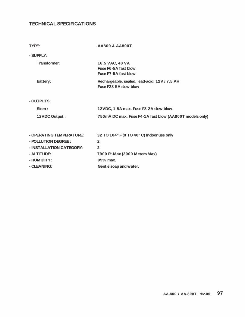
97AA-800 / AA-800T rev.06
TECHNICAL SPECIFICATIONS
TYPE: AA800 & AA800T
- SUPPLY:
Transformer: 16.5 VAC, 40 VAFuse F6-5A fast blowFuse F7-5A fast blow
Battery: Rechargeable, sealed, lead-acid, 12V / 7.5 AHFuse F28-5A slow blow
- OUTPUTS:
Siren : 12VDC, 1.5A max. Fuse F8-2A slow blow.
12VDC Output : 750mA DC max. Fuse F4-1A fast blow (AA800T models only)
- OPERATING TEMPERATURE: 32 TO 104°F (0 TO 40°C) Indoor use only
- POLLUTION DEGREE : 2
- INSTALLATION CATEGORY: 2
- ALTITUDE: 7900 Ft.Max (2000 Meters Max)
- HUMIDITY: 95% max.
- CLEANING: Gentle soap and water.


REGISTRATION CARD
AGRI-ALERT 800 & AGRI-ALERT 800T
Please fill out the following form to receive information on future updates.
Name:
Address :
City:
Phone number:
Fax number:
E-mail:
Purchased from:
Date purchased:
Serial Number:
Software Version Number:(Press the System key)
Fax this page to: (450) 926-2780