Embed Size (px)
Citation preview

Manual Part Manual Rev
MV 1 SERIES
GAS GRILL
OWNER’S MANUAL
Click here for
Parts List
No: 931760-01 MV1 Gas Grill - 1 – No: 1
Manual Part No: 931760-01 MV1 Gas Grill - 2 – Manual Rev No: 1
IMPORTANT CUSTOMER INFORMATION Please check the gas tap will press and release freely prior to lighting the burner, as this is part of the unit’s safety mechanism. It is particularly important to check this following spillage as solidified fats and carbonised meat juices can impair the valves correct operation.
IMPORTANT INFORMATION INSTALLATION ENGINEER Please ensure the customer is made fully aware of how the gas tap and the importance of checking its operation daily.
Manual Part No: 931760-01 MV1 Gas Grill - 3 – Manual Rev No: 1
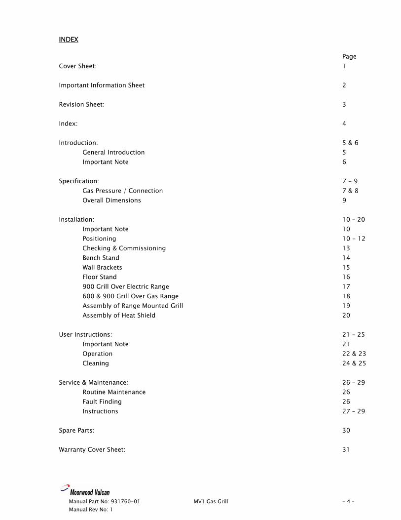
Model No. Product Description Rev. Date Flexible Hose
Size
MV1GSA60-NG MV1GSA60-LP
MV1GSA90-NG MV1GSA90-LP
MV Gas Grills 600 Salamander Grill 600 Salamander Grill 900 Salamander Grill 900 Salamander Grill
1 1
2 2
03/01/05 03/01/05
06/07/05 06/07/05
½” BSP hose ½” BSP hose
½” BSP hose ½” BSP hose
Manual Part No: 931760-01 MV1 Gas Grill - 4 – Manual Rev No: 1
INDEX
Page Cover Sheet: 1 Important Information Sheet 2 Revision Sheet: 3 Index: 4 Introduction: 5 & 6
General Introduction 5 Important Note 6
Specification: 7 - 9
Gas Pressure / Connection 7 & 8 Overall Dimensions 9
Installation: 10 – 20
Important Note 10 Positioning 10 - 12 Checking & Commissioning 13 Bench Stand 14 Wall Brackets 15 Floor Stand 16 900 Grill Over Electric Range 17 600 & 900 Grill Over Gas Range 18 Assembly of Range Mounted Grill 19 Assembly of Heat Shield 20
User Instructions: 21 – 25
Important Note 21 Operation 22 & 23 Cleaning 24 & 25
Service & Maintenance: 26 – 29
Routine Maintenance 26 Fault Finding 26 Instructions 27 – 29
Spare Parts: 30 Warranty Cover Sheet: 31
Manual Part No: 931760-01 MV1 Gas Grill - 5 – Manual Rev No: 1
INTRODUCTION This manual contains all the required information to ensure that your new appliance is installed correctly and that you have all the information necessary to identify and order spare parts. It also contains comprehensive instructions for the user and for cleaning the appliance. To maintain peak performance, it is recommended that the appliance be regularly serviced and that when ordering spare parts, reference be made to the appropriate list quoting the Part No. and the description therein. THE FITTING OF A NON-STANDARD PART MAY VOID ANY GUARANTEE. All work carried out on this appliance during installation or servicing must be performed by a competent person and the connection of the appliance to the gas supply MUST be carried out by qualified personnel in accordance, where applicable, with the relevant regulations. The siting of the appliance and the connection to the gas supply must comply with the latest GAS SAFETY (INSTALLATION & USE) REGULATIONS 2000: the requirements of the FIRE PRECAUTIONS ACT 1971; the HEALTH & SAFETY AT WORK, ETC ACT 1974, the BUILDING STANDARDS (SCOTLAND) CONSOLIDATION REGULATIONS 1971. Detailed recommendations are contained in British Standards BS5440 Part 1:2000, BS5440 Part 2:2000, BS5588: Part 0:1996, BS5588: Part 11:1997 & BS6173: 2001 An easily accessible stopcock must be fitted in the gas supply adjacent to the appliance for use in emergency. In addition a fused mains isolator must be fitted in the electricity supply. The details of the gas supply will be found on the Data Plate, which is located on the rear of the flue upstand/splashback panel. Improvements The policy of Viscount Catering Ltd is such that, each product is subject to continual development and may, therefore, be subsequently improved. The company reserves the right to alter the design of any appliance without prior notification and without the responsibility to update any delivered or in-service appliance and furthermore, without incurring the responsibility for altering these instructions. In such circumstances, it may be found that the appliance detailed herein differs in certain respects from the one supplied. IT IS IMPORTANT, THEREFORE, TO QUOTE THE SERIAL No. AND THE APPLIANCE MODEL No. IN ALL COMMUNICATIONS WITH THE COMPANY.
Manual Part No: 931760-01 MV1 Gas Grill - 6 – Manual Rev No: 1
Introduction (cont.) Important Before installing any item please refer to the installation instructions. We recommend that all servicing other than routine cleaning be carried out by our authorised service agents and will accept no responsibility for work carried out by other persons. For satisfactory operation parts of catering equipment become hot. Suitable precautions must be taken to avoid accidental burns therefore the appliance should be positioned to minimise the possibility of accidental touching. It is the supervisors’ responsibility to warn users to wear suitable protection and to follow correct operation and cleaning procedures. For the details of your nearest Service Agent for all warranty and repair work, you should contact: - The Service Manager, Viscount Catering Limited Provincial Park Nether Lane Ecclesfield Sheffield S35 9ZX Tel: +44 (0) 114 2574500 Fax: +44 (0) 114 2574527 Spares can be obtained via the Spare Parts Department at the above address. IT IS IMPORTANT, TO QUOTE THE SERIAL No. AND THE APPLIANCE MODEL No. IN ALL COMMUNICATIONS WITH THE COMPANY.
Manual Part No: 931760-01 MV1 Gas Grill - 7 – Manual Rev No: 1
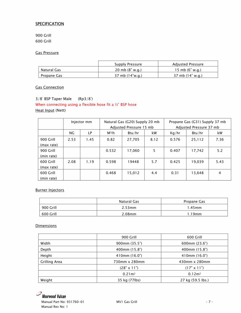
SPECIFICATION 900 Grill 600 Grill Gas Pressure
Supply Pressure Adjusted Pressure Natural Gas 20 mb (8” w.g.) 15 mb (6” w.g.) Propane Gas 37 mb (14”w.g.) 37 mb (14” w.g.)
Gas Connection 3/8” BSP Taper Male (Rp3/8”) When connecting using a flexible hose fit a ½” BSP hose Heat Input (Nett)
Injector mm Natural Gas (G20) Supply 20 mb Adjusted Pressure 15 mb
Propane Gas (G31) Supply 37 mb Adjusted Pressure 37 mb
NG LP M³/h Btu/hr kW Kg/hr Btu/hr kW
900 Grill (max rate)
2.53 1.45 0.82 27,705 8.12 0.576 25,112 7.36
900 Grill (min rate)
0.532 17,060 5 0.407 17,742 5.2
600 Grill (max rate)
2.08 1.19 0.598 19448 5.7 0.425 19,039 5.43
600 Grill (min rate)
0.468 15,012 4.4 0.31 13,648 4
Burner Injectors
Natural Gas Propane Gas 900 Grill 2.53mm 1.45mm
600 Grill 2.08mm 1.19mm Dimensions
900 Grill 600 Grill Width 900mm (35.5”) 600mm (23.6”) Depth 400mm (15.8”) 400mm (15.8”) Height 410mm (16.0”) 410mm (16.0”) Grilling Area 730mm x 280mm 430mm x 280mm (28” x 11”) (17” x 11”) 0.21m2 0.12m2
Weight 35 kg (77lbs) 27 kg (59.5 lbs.)
Manual Part No: 931760-01 MV1 Gas Grill - 8 – Manual Rev No: 1
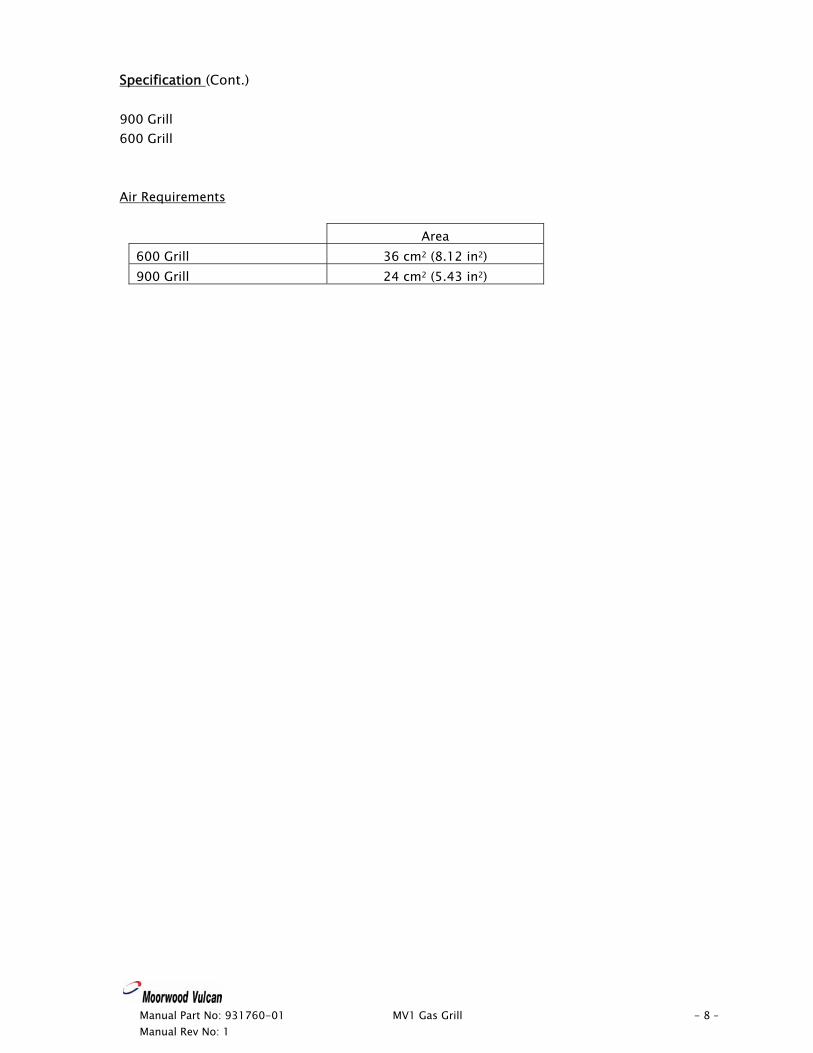
Specification (Cont.) 900 Grill 600 Grill Air Requirements
Area 600 Grill 36 cm2 (8.12 in2)
900 Grill 24 cm2 (5.43 in2)
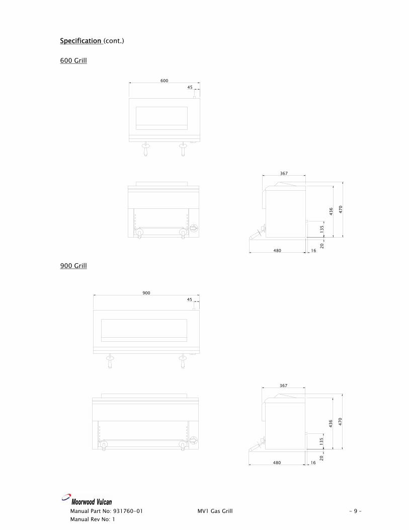
Specification (cont.) 600 Grill 600
45
367
480 16
470
436
135
20
90045
367
480 16
470
436
135
20
900 Grill
Manual Part No: 931760-01 MV1 Gas Grill - 9 – Manual Rev No: 1
Manual Part No: 931760-01 MV1 Gas Grill - 10 – Manual Rev No: 1
INSTALLATION Important Your attention is drawn to the latest GAS SAFETY (INSTALLATION & USE) REGULATIONS 2000. This appliance MUST be installed by a competent person in accordance with these and any other relevant regulations. Users, too, should be aware of the regulations governing the use of gas appliances, particularly with respect to the need for regular servicing. Your attention is drawn to the requirement that those parts, which have been protected by the manufacturer or his agent, are not to be adjusted by the installer. Before Installation Before commencing installation, remove all packaging materials from the appliance. It is suggested that any protective film adhering to the stainless steel panels should be left on until installation is completed. BUT THIS MUST BE REMOVED BEFORE COMMISSIONING OR OPERATING THE APPLIANCE. Check the appliance Data Plate (fitted to the back panel), to ensure that the appliance is suitable for the gas supply available. Ensure that the floor upon which the appliance is to stand is level and capable of adequately supporting the weight of the appliance. TO COMPENSATE FOR SOME UNEVENNESS OF THE FLOOR, THE APPLIANCE FEET ARE ADJUSTABLE. THE FLOOR MUST BE FIRE PROOF. If it is not, or if any adjacent wall or surface is made of a combustible material, then the installer MUST ensure that the requirements of the LOCAL FIRE REGULATIONS are observed. Positioning The grill may be mounted on a floor stand (page 14), on a bench stand (page 12), on wall brackets (page 13) or above a range (pages 15,16 & 17). The grill should be positioned clear of any adjacent walls by a minimum of 150mm (6”) on all sides. It is also recommended that a minimum distance of 450mm (17.7”)* be allowed between the top of the appliance and any shelf or ceiling. *This distance MUST be 600mm (24”) when the ceiling or overshelf is made from combustible material. There should be a minimum distance of 430mm (17”) between the bottom of the appliance and any solid or open top burners below.
Manual Part No: 931760-01 MV1 Gas Grill - 11 – Manual Rev No: 1
Installation (cont.) Positioning (cont.) Adequate ventilation is essential for safe operation of a gas appliance. A supply of fresh air is necessary for the correct combustion of the gas and there must be a means of exhausting the heat and the products of combustion from the kitchen. It is recommended that the appliance be sited below a ventilating hood, one preferably connected to an extractor system incorporating a grease filter. These appliances are to be installed with sufficient ventilation to prevent the occurrence of unacceptable concentrations of substances harmful to health in the room in which they are installed. If the grill is to be positioned in such a way that it is possible to touch the rear of the grill when hot, then a Heat Shield (available as an accessory) MUST be fitted to the back panel. Accessory Kit. - CL6G-HS Heat Shield Kit (600 Grill)
CL9G-HS Heat Shield Kit (900 Grill) Important Note The appliance MUST NOT be connected DIRECTLY to a flue or ventilating system, although the flue products of two or more appliances may be directed into a common outlet when building a suite of appliances (see separate instructions for suiting appliances). Ensure that the appliance is level in two places - front to rear and side to side. To check the level it is recommended that a spirit level be placed on the toast rack. Gas Connection Natural Gas: The size of the supply pipe should be no smaller than 3/8” BSP and an easily accessible stopcock must be fitted in the gas line adjacent to the appliance. The gas governor provided with the appliance MUST be fitted in the supply line BETWEEN the stopcock and the appliance. Although a rigid gas pipe is recommended, armoured flexible pipe of a GAS COUNCIL APPROVED PATTERN may be used. Ensure that all the pipes to the appliance are clean and free from swarf etc, BEFORE making the final connection. Propane Gas: Follow the same procedure as that for Natural Gas EXCEPT that the Gas Governor MUST NOT be fitted - the Gas Supply Tank or Cylinders are already fitted with a Gas Regulator.
Manual Part No: 931760-01 MV1 Gas Grill - 12 – Manual Rev No: 1
Installation (cont.) Leak Test Clean off any protective film from the stainless steel panels. AT THIS STAGE, LEAK TEST THE WHOLE SYSTEM. THE GAS SAFETY REGULATIONS require that ALL connections in the gas supply line between the Gas Meter and the appliance is tested for gas leaks. THIS MUST BE DONE BEFORE COMMENCING TO COMMISSION THE APPLIANCE. Checking and commissioning ALTHOUGH EVERY APPLIANCE IS TESTED AND SET BEFORE IT LEAVES THE FACTORY, IT IS IMPORTANT THAT THE INSTALLER RE-CHECKS CERTAIN FUNCTIONS BEFORE LEAVING THE SITE. CHECK THE GAS PRESSURE AT THE APPLIANCE THUS: - The pressure test point is located behind the Grill, on the gas Inlet pipe. Connect a manometer (U tube) to the test point. Turn on the gas supply and light the Burner. Check that the pressure reading agrees with that stated on the Data Plate. SHOULD ADJUSTMENT BE NECESSARY, PROCEED AS FOLLOWS: - FOR PROPANE GAS, REFER TO SUPPLIER. On the gas governor: Remove the cap in order to gain access to the pressure adjusting screw. Turn the pressure adjusting screw clockwise to increase the pressure or anti-clockwise to decrease it. When the pressure reading is correct, refit the cap to the governor. Turn the gas supply to the unit OFF at the stopcock and disconnect the manometer (U tube). Ensure that the pressure test point screw is refitted. Turn the gas supply to the appliance on at the stopcock and leak test the pressure test point.
Manual Part No: 931760-01 MV1 Gas Grill - 13 – Manual Rev No: 1
Installation (cont.) Checking and commissioning (cont.) Burner Aeration The aeration of all the burners is fixed and does not need adjusting. Note: - The grill burner is partially blocked off (approximately a 50mm strip in the centre of the burner) this is to give even heat distribution across the Toast Rack/Brander Plate. This appliance must be equipotentially earth bonded.
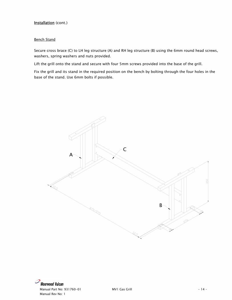
Installation (cont.) Bench Stand Secure cross brace (C) to LH leg structure (A) and RH leg structure (B) using the 6mm round head screws, washers, spring washers and nuts provided.
Lift the grill onto the stand and secure with four 5mm screws provided into the base of the grill.
Fix the grill and its stand in the required position on the bench by bolting through the four holes in the base of the stand. Use 6mm bolts if possible.
A
B
C
Manual Part No: 931760-01 MV1 Gas Grill - 14 – Manual Rev No: 1
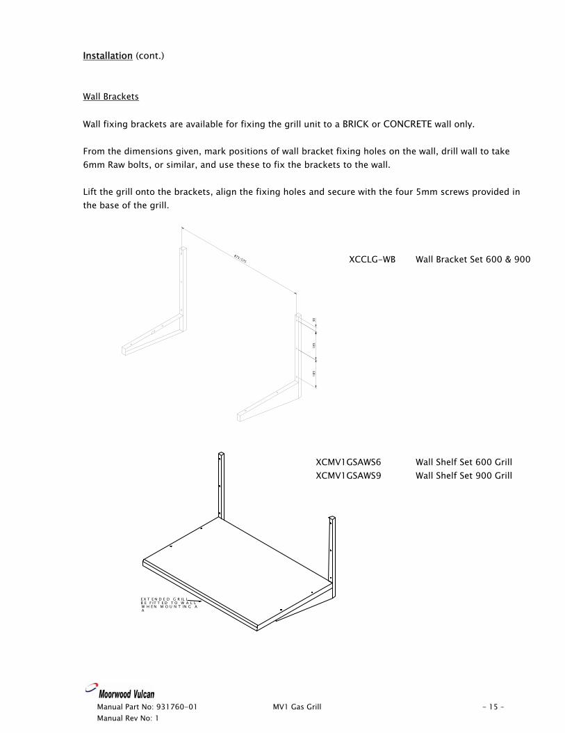
Installation (cont.) Wall Brackets Wall fixing brackets are available for fixing the grill unit to a BRICK or CONCRETE wall only. From the dimensions given, mark positions of wall bracket fixing holes on the wall, drill wall to take 6mm Raw bolts, or similar, and use these to fix the brackets to the wall. Lift the grill onto the brackets, align the fixing holes and secure with the four 5mm screws provided in the base of the grill.
875/575
185
185
30
XCCLG-WB Wall Bracket Set 600 & 900
XCMV1GSAWS6 Wall Shelf Set 600 Grill
XCMV1GSAWS9 Wall Shelf Set 900 Grill
E X T E N D E D G R IL LB E F IT T E D T O W A L LW H E N M O U N T IN G AA
Manual Part No: 931760-01 MV1 Gas Grill - 15 – Manual Rev No: 1
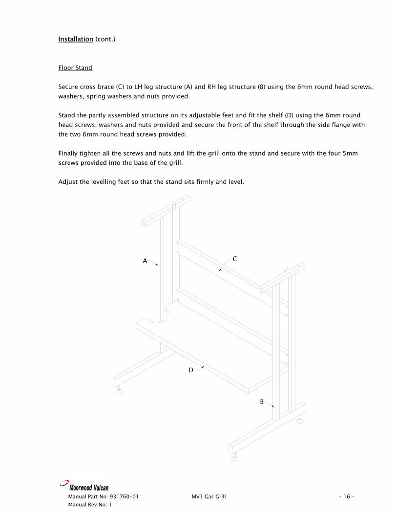
Installation (cont.) Floor Stand Secure cross brace (C) to LH leg structure (A) and RH leg structure (B) using the 6mm round head screws, washers, spring washers and nuts provided. Stand the partly assembled structure on its adjustable feet and fit the shelf (D) using the 6mm round head screws, washers and nuts provided and secure the front of the shelf through the side flange with the two 6mm round head screws provided. Finally tighten all the screws and nuts and lift the grill onto the stand and secure with the four 5mm screws provided into the base of the grill. Adjust the levelling feet so that the stand sits firmly and level.
A
B
C
D
Manual Part No: 931760-01 MV1 Gas Grill - 16 – Manual Rev No: 1
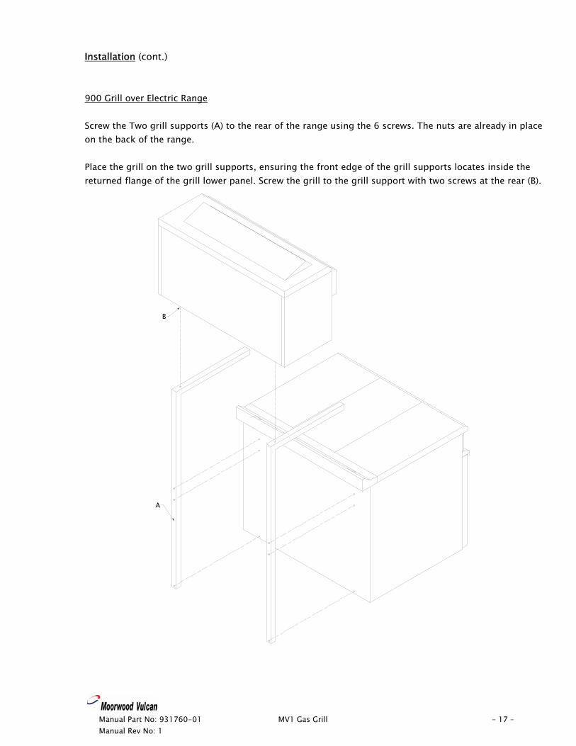
Installation (cont.) 900 Grill over Electric Range Screw the Two grill supports (A) to the rear of the range using the 6 screws. The nuts are already in place on the back of the range. Place the grill on the two grill supports, ensuring the front edge of the grill supports locates inside the returned flange of the grill lower panel. Screw the grill to the grill support with two screws at the rear (B).
A
B
Manual Part No: 931760-01 MV1 Gas Grill - 17 – Manual Rev No: 1
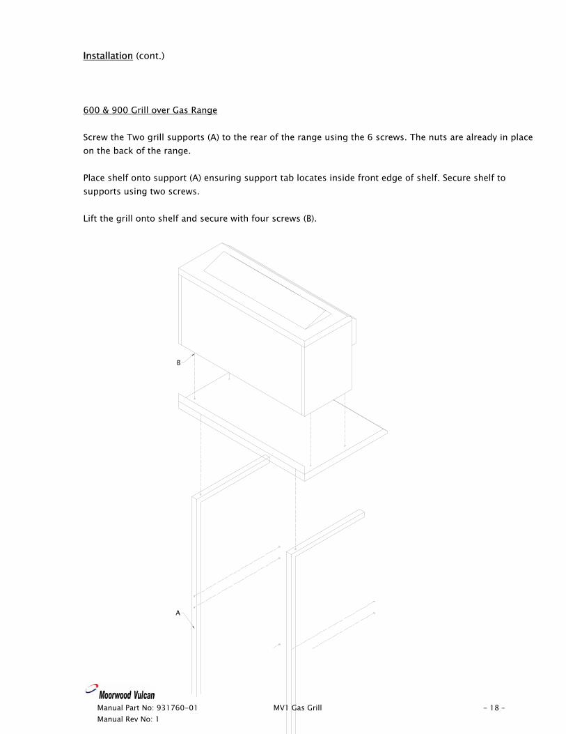
Installation (cont.) 600 & 900 Grill over Gas Range Screw the Two grill supports (A) to the rear of the range using the 6 screws. The nuts are already in place on the back of the range. Place shelf onto support (A) ensuring support tab locates inside front edge of shelf. Secure shelf to supports using two screws. Lift the grill onto shelf and secure with four screws (B).
Manual Part No: 931760-01 MV1 Gas Grill - 18 – Manual Rev No: 1
A
B
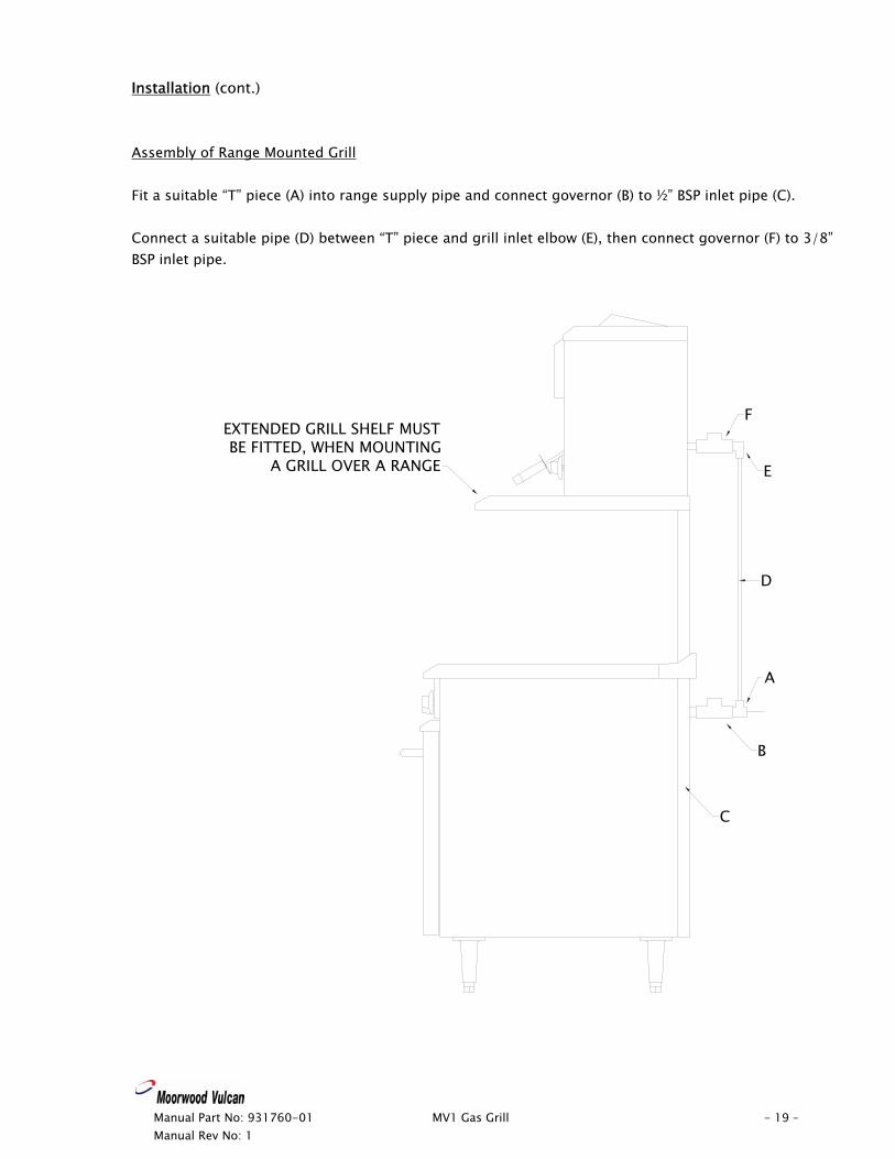
Installation (cont.) Assembly of Range Mounted Grill Fit a suitable “T” piece (A) into range supply pipe and connect governor (B) to ½” BSP inlet pipe (C). Connect a suitable pipe (D) between “T” piece and grill inlet elbow (E), then connect governor (F) to 3/8” BSP inlet pipe.
A
B
C
D
E
FEXTENDED GRILL SHELF MUSTBE FITTED, WHEN MOUNTING
A GRILL OVER A RANGE
Manual Part No: 931760-01 MV1 Gas Grill - 19 – Manual Rev No: 1
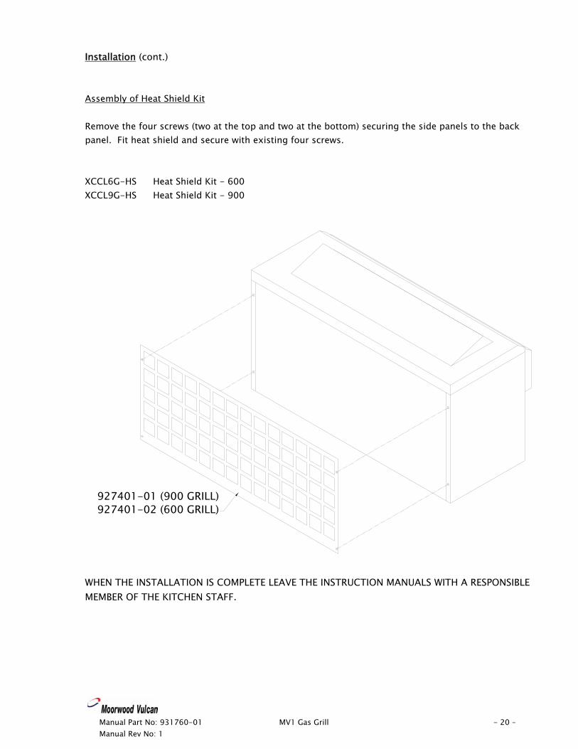
Installation (cont.) Assembly of Heat Shield Kit Remove the four screws (two at the top and two at the bottom) securing the side panels to the back panel. Fit heat shield and secure with existing four screws. XCCL6G-HS Heat Shield Kit - 600 XCCL9G-HS Heat Shield Kit - 900
927401-01 (900 GRILL)927401-02 (600 GRILL)
WHEN THE INSTALLATION IS COMPLETE LEAVE THE INSTRUCTION MANUALS WITH A RESPONSIBLE MEMBER OF THE KITCHEN STAFF.
Manual Part No: 931760-01 MV1 Gas Grill - 20 – Manual Rev No: 1
Manual Part No: 931760-01 MV1 Gas Grill - 21 – Manual Rev No: 1
USERS INSTRUCTIONS Important Note! The attention of the user is drawn to the requirements of the GAS SAFETY (INSTALLATION & USE) REGULATIONS 2000. This appliance must be used in accordance with those, particularly so in respect of the need for regular servicing. The attention of the user is also drawn to the requirement that those parts, which have been protected by the manufacturer or his agent, are not to be adjusted by the user. See also the sections of this manual referring to Cleaning and General Maintenance. Safety Note: This appliance is intended for professional use and shall only be used by qualified personnel. Parts and surfaces of this appliance get hot in use. It is the responsibility of the kitchen supervisor to inform and warn every user and kitchen worker of this and, furthermore, to ensure those users wear and use protective clothing when operating the appliance. Should any adjustment or attention be necessary, you are advised to contact your nearest CORGI (Confederation for the Registration of Gas Installers) Service Engineer immediately. The need for regular servicing is detailed in the GAS SAFETY (INSTALLATION & USE) REGULATIONS 2000. IF YOU THINK THAT GAS IS ESCAPING, ACT IMMEDIATELY. SHUT OFF THE GAS SUPPLY AT THE METER OR EMERGENCY CONTROL; CONTACT THE SUPPLIER OF YOUR GAS IMMEDIATELY. MAKE SURE THAT ALL USERS OF THIS APPLIANCE KNOW WHERE THE GAS SUPPLY STOPCOCK IS LOCATED FOR THE USE IN AN EMERGENCY. Improvements The policy of Viscount Catering Ltd is such that each product is subject to continual improvement. The company reserves the right to alter the design of any appliance without prior notification and without the responsibility to update any delivered or in-service appliance and, furthermore, without incurring the responsibility for altering these instructions. In such circumstances, it may be found that the appliance detailed herein differs in certain respect from the one supplied. For further details or enquires please contact: Viscount Catering Limited Provincial Park, Nether Lane, Ecclesfield, Sheffield, S35 9ZX Tel: +44 (0) 114 2570100 Fax: +44 (0) 114 2570251
Manual Part No: 931760-01 MV1 Gas Grill - 22 – Manual Rev No: 1
Users Instructions (cont.) Lighting the Grill 1) Turn on the gas supply. 2) Push-in and turn the Gas Tap anti-clockwise to the large double flame position, and apply a
lighted taper to light the burner. 3) Hold knob depressed for a further 30 seconds release and check that the burner remains alight. 4) If the burner is extinguished on releasing knob, repeat steps 2 & 3. 5) Rotate the control knob to the single flame position for minimum heat setting. Note: - When first lighting the appliance after installation or after an extended shut-down period, it may be necessary for the control knob to remain pushed-in for some time before the burner will light, owing to the presence of air in the gas line. To Turn Off 1) For short periods, turn the control knob clockwise to the OFF position λ. 2) For longer periods, turn the control knob clockwise to the OFF position λ, and close external
stopcock. Note: - The grill burner is partially blocked off (approximately a 50mm strip in the centre of the burner) this is to give even heat distribution across the Toast Rack/Brander Plate. Using the Toast Rack The toast rack has a detachable crumb tray to catch falling crumbs etc; when the grill is withdrawn. The grill can be used in any of the five runner positions, but for toast it is recommended that the rack be horizontal and in the second position from the top, with the heat on FULL. 900 Grill 12 slices can be toasted simultaneously. 600 Grill 6 slices can be toasted simultaneously. The toast rack may be used for a small quantity of foods, such as sausages or bacon, but the crumb tray is NOT designed to hold a large accumulation of fat. If the grill is used for this purpose, it is ESSENTIAL TO REMOVE AND CLEAN THE TRAY to avoid any fat deposits catching fire.
Manual Part No: 931760-01 MV1 Gas Grill - 23 – Manual Rev No: 1
Users Instructions (cont.) Using the Brander The Brander is supplied with a detachable grease trough intended for the collection of fat. The Brander can be positioned level, or at different angles as required for cooking, but the front pegs must always be positioned in the front locations on the sides to ensure the Brander does not move. Care should be taken when removing the Brander to prevent spillage of fat from the trough. The pre-heated Brander will brand and brown steaks on the underside. The food on the Brander may be unloaded in situ. Alternatively, the Brander should be COMPLETELY WITHDRAWN from the grill for unloading or cleaning purposes. When cooking steak, it is necessary to pre-heat the Brander for 15 minutes in the grilling position. It should be noted that pre-heating the Brander very close to the burner plaques could lead to deterioration/twisting of the Brander. Cooking Steak Steaks are normally cooked on a sloping Brander plate. Rare steaks are cooked at the rear of the Brander, i.e. nearest the burner. Steaks that are required to be well done should be cooked at the front of the Brander. Cooking Times It is not possible to give exact cooking times because of the variation in thickness and cuts of steak. However, as a general guide: - Steaks Rare 3 minutes
Well done 7 minutes Hamburgers/Beefburgers 2 minutes per side.
(At the centre of the Brander) Grilling When grilling, use the toast rack, but tall dishes may need to be placed directly on the base of the grill.
Manual Part No: 931760-01 MV1 Gas Grill - 24 – Manual Rev No: 1
Users Instructions (cont.) Cleaning It will be found that it takes less time and effort if appliances are cleaned every day, particularly while they are still warm and before grease and spillage’s are burnt on. PROPRIETARY OVEN CLEANER MUST BE USED WITH CARE, THEY ARE HIGHLY CORROSIVE AND MAY CAUSE DAMAGE TO SURFACES AND COMPONENTS. Clean stainless steel with soap and hot water or a mild detergent solution. Rinse and dry thoroughly. DO NOT USE CAUSTIC OR ABRASIVE CLEANERS, DO NOT USE ABRASIVE PADS. Vitreous enamelled surfaces should be wiped clean of grease and spillage BEFORE they are burnt on. Use a mild solution or grease dissolving agent or a detergent as a soak and wash. Accumulated deposits may be removed by soaking and then carefully scraping or by using a fine cleaning paste. DO NOT USE CAUSTIC CLEANERS The Brander plate is best cleaned whilst still warm. Surface grease and spillage should be removed by washing with soapy water. When deposits are baked on, it may be necessary to scrape the Brander plate with a metal utensil if a soap-filled wire wool pad is insufficient. Rinse thoroughly before re-fitting in the grill. DO NOT USE CAUSTIC CLEANERS DO NOT attempt to clean burner plaques: any deposits will burn off. If the grill is continuously used for grilling fatty products and is not cleaned, a thick coating of carbonised fat is likely to build up, both internally and externally, which can lead to loss of performance and the creation of a potential fire hazard. DO NOT DISTURB THE BURNER OR ELECTRODE (if fitted).
Manual Part No: 931760-01 MV1 Gas Grill - 25 – Manual Rev No: 1
Users Instructions (cont.) General Maintenance and Care This equipment is designed and manufactured to give you long, satisfactory service at low cost, provided that it is given proper care and attention at all times. Frequent cleaning and regular checking of correct adjustment will be rewarded by reduced operating and maintenance costs, minimum downtime, and regular results from your cooking. DO NOT POKE WIRE INTO BURNER PORTS OR ORIFICES TO CLEAR THEM OF OBSTRUCTION SEND FOR A QUALIFIED ENGINEER. All gas taps and control knobs must operate smoothly and freely without sticking or jerking. Re-lubrication MUST be carried out by a QUALIFIED ENGINEER. WE RECOMMEND THAT ALL EQUIPMENT IS SERVICED AT LEAST ONCE A YEAR, BUT MAY BE AS FREQUENT AS 6 MONTHS OR LESS IF THE GAS TAPS/THERMOSTAT AND GAS CONTROLS DO NOT OPERATE FREELY. ALL WORK MUST BE CARRIED OUT BY A QUALIFIED SERVICE ENGINEER. SERVICE INTERVALS CAN BE AFFECTED BY SPILLAGE AND SHOULD BE ASSESSED EACH TIME THE EQUIPMENT HAS BEEN USED.
Manual Part No: 931760-01 MV1 Gas Grill - 26 – Manual Rev No: 1
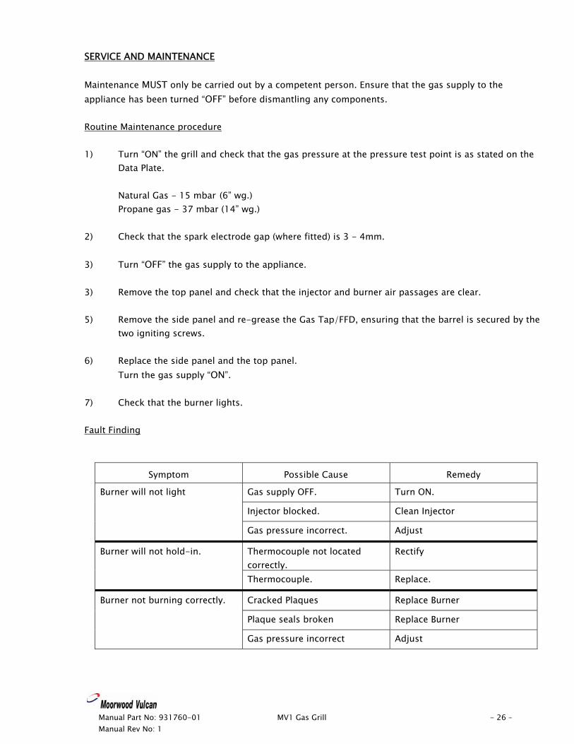
SERVICE AND MAINTENANCE Maintenance MUST only be carried out by a competent person. Ensure that the gas supply to the appliance has been turned “OFF” before dismantling any components. Routine Maintenance procedure 1) Turn “ON” the grill and check that the gas pressure at the pressure test point is as stated on the
Data Plate.
Natural Gas - 15 mbar (6” wg.) Propane gas - 37 mbar (14” wg.)
2) Check that the spark electrode gap (where fitted) is 3 - 4mm. 3) Turn “OFF” the gas supply to the appliance. 3) Remove the top panel and check that the injector and burner air passages are clear. 5) Remove the side panel and re-grease the Gas Tap/FFD, ensuring that the barrel is secured by the
two igniting screws. 6) Replace the side panel and the top panel.
Turn the gas supply “ON”. 7) Check that the burner lights. Fault Finding
Symptom Possible Cause Remedy
Gas supply OFF. Turn ON.
Injector blocked. Clean Injector
Burner will not light
Gas pressure incorrect. Adjust
Thermocouple not located correctly.
Rectify Burner will not hold-in.
Thermocouple. Replace.
Cracked Plaques Replace Burner
Plaque seals broken Replace Burner
Burner not burning correctly.
Gas pressure incorrect Adjust
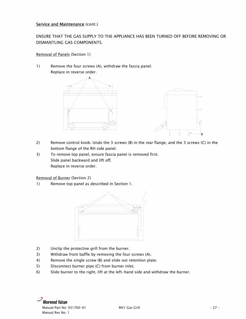
Service and Maintenance (cont.) ENSURE THAT THE GAS SUPPLY TO THE APPLIANCE HAS BEEN TURNED OFF BEFORE REMOVING OR DISMANTLING GAS COMPONENTS. Removal of Panels (Section 1) 1) Remove the four screws (A), withdraw the fascia panel.
Replace in reverse order.
Manual Part No: 931760-01 MV1 Gas Grill - 27 – Manual Rev No: 1
2) Remove control knob. Undo the 3 screws (B) in the rear flange, and the 3 screws (C) in the
bottom flange of the RH side panel. 3) To remove top panel, ensure fascia panel is removed first.
Slide panel backward and lift off. Replace in reverse order.
Removal of Burner (Section 2) 1) Remove top panel as described in Section 1. 2) Unclip the protective grill from the burner.
A
B
3) Withdraw front baffle by removing the four screws (A). 4) Remove the single screw (B) and slide out retention plate. 5) Disconnect burner pipe (C) from burner inlet. 6) Slide burner to the right, lift at the left-hand side and withdraw the burner.
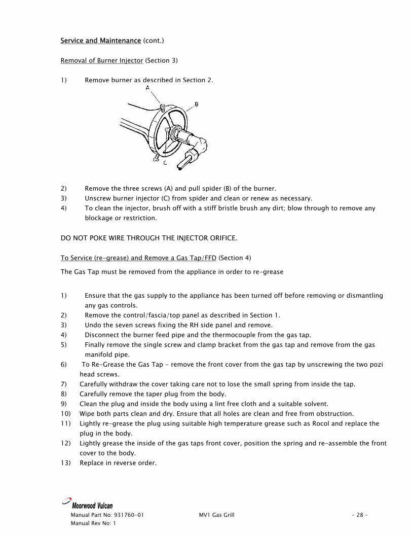
Service and Maintenance (cont.) Removal of Burner Injector (Section 3) 1) Remove burner as described in Section 2.
Manual Part No: 931760-01 MV1 Gas Grill - 28 – Manual Rev No: 1
2) Remove the three screws (A) and pull spider (B) of the burner. 3) Unscrew burner injector (C) from spider and clean or renew as necessary. 4) To clean the injector, brush off with a stiff bristle brush any dirt; blow through to remove any
blockage or restriction. DO NOT POKE WIRE THROUGH THE INJECTOR ORIFICE. To Service (re-grease) and Remove a Gas Tap/FFD (Section 4)
The Gas Tap must be removed from the appliance in order to re-grease
1) Ensure that the gas supply to the appliance has been turned off before removing or dismantling
any gas controls. 2) Remove the control/fascia/top panel as described in Section 1. 3) Undo the seven screws fixing the RH side panel and remove. 4) Disconnect the burner feed pipe and the thermocouple from the gas tap. 5) Finally remove the single screw and clamp bracket from the gas tap and remove from the gas
manifold pipe. 6) To Re-Grease the Gas Tap - remove the front cover from the gas tap by unscrewing the two pozi
head screws. 7) Carefully withdraw the cover taking care not to lose the small spring from inside the tap. 8) Carefully remove the taper plug from the body. 9) Clean the plug and inside the body using a lint free cloth and a suitable solvent. 10) Wipe both parts clean and dry. Ensure that all holes are clean and free from obstruction. 11) Lightly re-grease the plug using suitable high temperature grease such as Rocol and replace the
plug in the body. 12) Lightly grease the inside of the gas taps front cover, position the spring and re-assemble the front
cover to the body. 13) Replace in reverse order.
Service and Maintenance (cont.) To Convert NG Appliance to LP Gas (Section 5) 1) Remove panels as described in Section 1. 2) Remove burner injector as described in Section 3. 3) Fit new burner injector 1.45mm/280amal (924064-04) 900 Grill and 1.19mm/190amal
(924064-06) 600 Grill. 4) Screw by-pass screw fully in 5) Remove the governor from the gas supply line and reconnect. To Convert LP Appliance to NG Gas (Section 6) 1) Remove panels as described in Section 1. 2) Remove burner injector as described in Section 3. 3) Fit new burner injector 2.53mm/840amal (924064-03) 900 Grill and
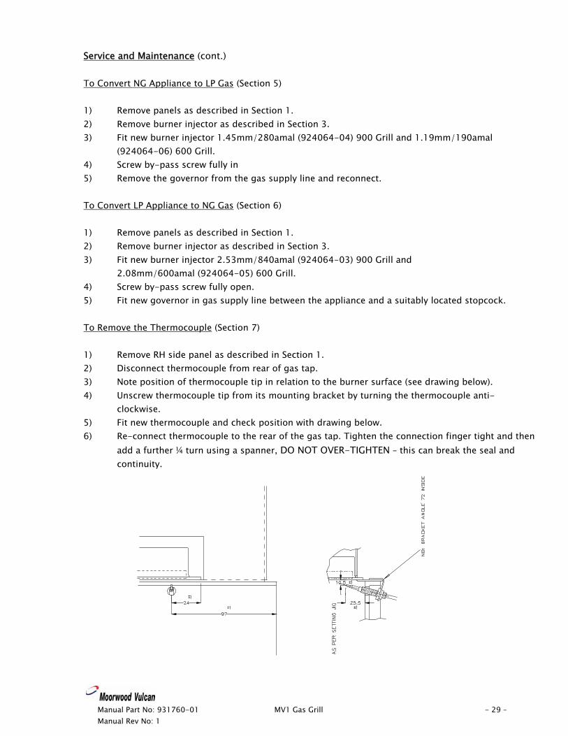
2.08mm/600amal (924064-05) 600 Grill. 4) Screw by-pass screw fully open. 5) Fit new governor in gas supply line between the appliance and a suitably located stopcock. To Remove the Thermocouple (Section 7) 1) Remove RH side panel as described in Section 1. 2) Disconnect thermocouple from rear of gas tap. 3) Note position of thermocouple tip in relation to the burner surface (see drawing below). 4) Unscrew thermocouple tip from its mounting bracket by turning the thermocouple anti-
clockwise. 5) Fit new thermocouple and check position with drawing below. 6) Re-connect thermocouple to the rear of the gas tap. Tighten the connection finger tight and then
add a further ¼ turn using a spanner, DO NOT OVER-TIGHTEN – this can break the seal and continuity.
Manual Part No: 931760-01 MV1 Gas Grill - 29 – Manual Rev No: 1
Manual Part No: 931760-01 MV1 Gas Grill - 30 – Manual Rev No: 1
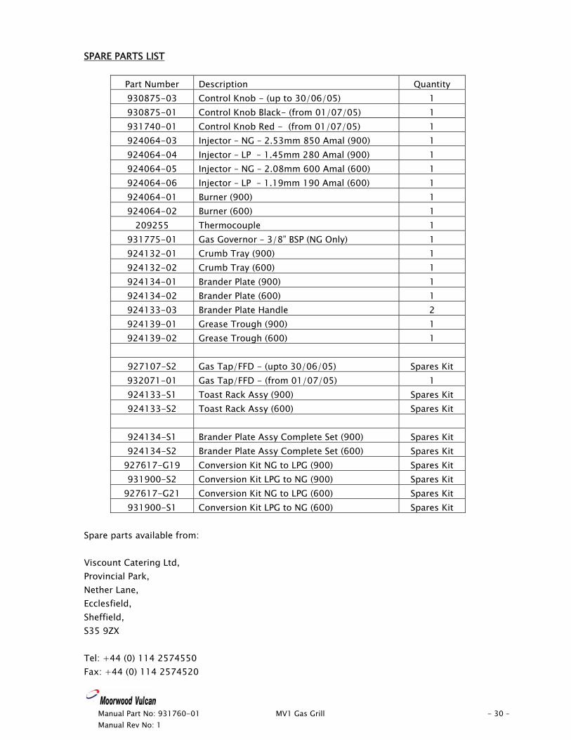
SPARE PARTS LIST
Part Number Description Quantity 930875-03 Control Knob - (up to 30/06/05) 1 930875-01 Control Knob Black- (from 01/07/05) 1 931740-01 Control Knob Red - (from 01/07/05) 1 924064-03 Injector – NG – 2.53mm 850 Amal (900) 1 924064-04 Injector – LP – 1.45mm 280 Amal (900) 1 924064-05 Injector – NG – 2.08mm 600 Amal (600) 1 924064-06 Injector – LP – 1.19mm 190 Amal (600) 1 924064-01 Burner (900) 1 924064-02 Burner (600) 1
209255 Thermocouple 1 931775-01 Gas Governor – 3/8” BSP (NG Only) 1 924132-01 Crumb Tray (900) 1 924132-02 Crumb Tray (600) 1 924134-01 Brander Plate (900) 1 924134-02 Brander Plate (600) 1 924133-03 Brander Plate Handle 2 924139-01 Grease Trough (900) 1 924139-02 Grease Trough (600) 1
927107-S2 Gas Tap/FFD - (upto 30/06/05) Spares Kit 932071-01 Gas Tap/FFD - (from 01/07/05) 1 924133-S1 Toast Rack Assy (900) Spares Kit 924133-S2 Toast Rack Assy (600) Spares Kit
924134-S1 Brander Plate Assy Complete Set (900) Spares Kit 924134-S2 Brander Plate Assy Complete Set (600) Spares Kit
927617-G19 Conversion Kit NG to LPG (900) Spares Kit 931900-S2 Conversion Kit LPG to NG (900) Spares Kit
927617-G21 Conversion Kit NG to LPG (600) Spares Kit 931900-S1 Conversion Kit LPG to NG (600) Spares Kit
Spare parts available from: Viscount Catering Ltd, Provincial Park, Nether Lane, Ecclesfield, Sheffield, S35 9ZX Tel: +44 (0) 114 2574550 Fax: +44 (0) 114 2574520

Manual Part No: 931760-01 MV1 Gas Grill - 31 – Manual Rev No: 1
Manual Part No: 931760-01 MV1 Gas Grill - 32 – Manual Rev No: 1
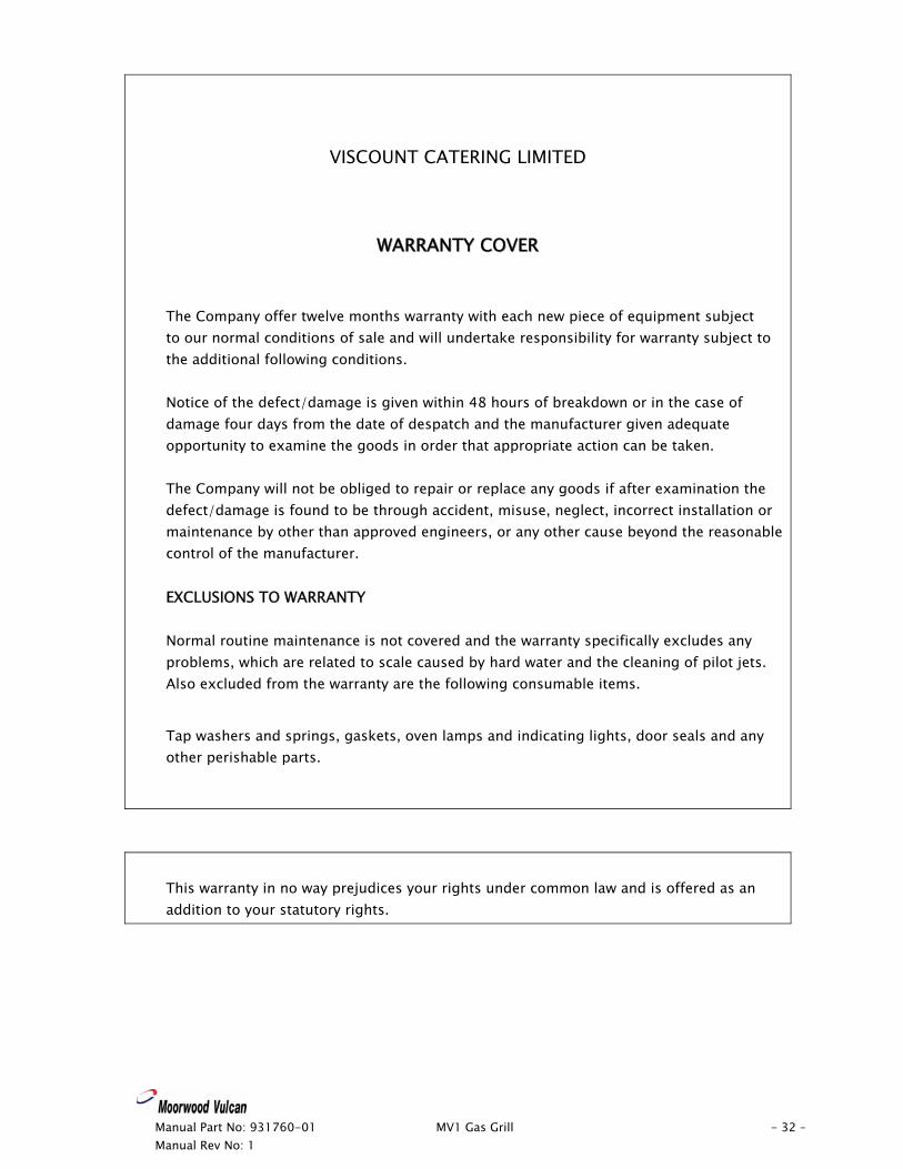
VISCOUNT CATERING LIMITED
WWAARRRRAANNTTYY CCOOVVEERR
The Company offer twelve months warranty with each new piece of equipment subject to our normal conditions of sale and will undertake responsibility for warranty subject to the additional following conditions. Notice of the defect/damage is given within 48 hours of breakdown or in the case of damage four days from the date of despatch and the manufacturer given adequate opportunity to examine the goods in order that appropriate action can be taken. The Company will not be obliged to repair or replace any goods if after examination the defect/damage is found to be through accident, misuse, neglect, incorrect installation or maintenance by other than approved engineers, or any other cause beyond the reasonable control of the manufacturer. EXCLUSIONS TO WARRANTY Normal routine maintenance is not covered and the warranty specifically excludes any problems, which are related to scale caused by hard water and the cleaning of pilot jets. Also excluded from the warranty are the following consumable items.
Tap washers and springs, gaskets, oven lamps and indicating lights, door seals and any other perishable parts.
This warranty in no way prejudices your rights under common law and is offered as an addition to your statutory rights.