Embed Size (px)
Citation preview

M SERIES CONNECTORSRATCHET COUPLING


1www.lemo.com
® ®
IntroductionThis catalogue gives the complete description of LEMO M series connectors. M series connectors are lightweight triple-start ratchet coupling type connectors designed for avionics, aerospace, military, security, motorsport and heavy duty appli-cations. The LEMO manufacturing programme has been extended to almost 40 series divided into 7 product families with specificmating and environmental characteristics. Each series includes a wide variety of plug, socket and coupler models, avail-able in contact configurations adapted to all round cables. Watertight models are also available. Since LEMO connectorsare perfectly screened and designed to guarantee very low resistance to shell electrical continuity, they are particularly adaptedto applications where electromagnetic compatibility (EMC) is important.
Technical Characteristics
Component
Outer shell
Conical nut
Earthing crown
Coupling nut
Ratchet
Hexagonal nut
Male crimp contactFemale crimp contactClipsInsulator
O-ring
Sealing resinCable rear sealSpring
Material (Standard)
Brass (UNS C 38500)Aluminium alloy (AA 6262A or AA 6023)Brass (UNS C 38500)Aluminium alloy (AA 6262A or AA 6023)Bronze (UNS C 54400) or special brassBrass (UNS C 38500)Aluminium alloy (AA 6262A or AA 6023)Special PEEKBrass (UNS C 38500)Aluminium alloy (AA 6262A or AA 6023)Brass (UNS C 34500)Bronze (UNS C 54400)Cu-Be or special steelPEEKSiliconeFPM/FKM (Viton®)Epoxy (Araldite® or Stycast®)FluorosiliconeStainless steel
Shellmaterial code
X C
0.5 3 0.3 – – – – –– – – – 5 – – – 1)
0.5 3 0.3 – – – – –– – – – 5 – – – 1)
– – – – – 0.5 – 1.5– – – 0.5 3 – – –– – – 0.5 3 – – –– – – 0.5 3 – – –– – – 0.5 3 – – –– – – – 5 – – –– – – – – 0.5 3 1.0– – – – – 0.5 3 1.5
without treatment––––––
Surface treatment (µm)chrome nickel gold
Cu Ni Cr Cu Ni Cu Ni Au
Materials and Treatments
Notes
Notes: standards for surface treatment are as follows: chrome-plated FS QQ-C-320B; nickel-plated FS QQ-N-290A or MIL-C-26074C; gold-plated ISO4523. 1) anthracite colour.
- 55°C/+200°CIP 68 (at 2 m, 15 hr) IEC 60529Satisfied - by material analysis MIL-STD 810F-508.560 sec. front and back face EIA-364-104AFuels, gasoline, hydraulic oils, solvents, de-icing MIL-STD-810F method 5046 hr, 55°C, blowing < 150 µm dust MIL-STD 810F-510.410 K amps - 6 times EIA-364-75-65°C; 40’000 feet and 400 VAC EIA-364-105AAlum. shell (slight pitting after 48h), Brass shell (500h) IEC 60512-6 test 11f EIA-364-265 cycles: -65°C to +150°C IEC 60512-11-4 EIA-364-32 test condition IVNo moisture on contacts EIA-364-03< 10-7 mbar. l /sec (Helium) IEC 60512-7 14 b MIL-STD-1344 method 1008.121 days at 95% IEC 60068-2 EIA-364-31 method IV
Operating temperature (mated)Ingress protection indexFungusFlammabilityFluid contamination 1)
Sand and dust 2)
Lightning strikeAltitude-low temp 3)
Salt fog 4)
Thermal shockAltitude immersionAir leakage 5)
Humidity
Characteristics Value IEC international MIL-spec tests
Environmental performance
Note:1) Connectors immersed at both 70°C and 25°C according to specification. Connectors are then inspected, no visual signs of damage seen.
Fuels: Kerosene, JP4, (Nato F40) at 70°C +/- 2°C. Gasoline: ASTM 4814. Hydraulic oils: Mineral oil based MIL-H-5606.Solvents: Isopropanol. De-icing fluids: 25% ethylene glycol.
2) No signs of damage, connectors opened and closed without difficulty. Dust or sand was not inside connector. 3) Wired mated connectors = no voltage breakdown, shell to all contacts (connected together) w/400 VAC after 1 hour at 65° C
at 40’000 feet altitude.4) Corrosion resistance. Inspection: salt deposits shall be removed by gentle wash in running water with light brushing using soft brush.
Aluminium Shell (material code: X) max: 96 hours. Brass shell (material code: C) over 500 hours.5) Only for vacuumtight model (HE•)
EnduranceGunfire vibrationVibration-Sine 8)
Vibration-RandomShockAccelerationContact retentionTorque
2 www.lemo.com
® ®
> 1012 Ω, > 1010 Ω (after humidity) IEC 60512-2 test 3a EIA-364-21See table page 16-17 IEC 60512-2 test 4a EIA-364-20See table below 7) IEC 60512-2 test 2a EIA-364-06See insulator configuration page 16-17 IEC 60512-3 test 5a< 1.5mΩ IEC 60512-2-6 EIA-364-83≥ 80 dB up to 1GHz EIA-364-66≥ 70 dB (3GHz), ≥ 58 dB (6GHz), ≥ 40 dB (10GHz) EIA-364-66
Insulation resist. (at ambient temp.) 6)
Dielectric withstanding volt. (sea level)Contact resistanceCurrent ratingShell to shell conductivityShielding effectiveness, low frequencyShielding effectiveness, high frequency
Electrical performance
Characteristics Value IEC international MIL-spec tests
Note: 6) After humidity test: 21 days at 95% RH according to IEC 60068-2. Insulation resistance measured between the contacts and contact/shell.
Notes: 7) after 5000 mating cycles and the salt spray test according to IEC 60512-6 test 11 f.
Value
ø A(mm)
mΩ
Contact resistance 7)IEC 60512-2 test 2a
0.5 0.7 0.9 1.3
≤ 8.7 ≤ 6.1 ≤ 4.8 ≤ 3.6
3000 cycles IEC 60512-5 test 9a EIA-364-0925 to 2000 Hz, 3 axis (Apache helicopter) MIL-STD-810F method 519.530 g, 3 axis, 12 hr MIL-STD-202 method 204-G50-2000 Hz, 37.8 g rms-3 axes; 4h amb IEC 60512-6-4 EIA-364-28 test cond. V letter I300 g - 3 msec IEC 60512-6-3 EIA-364-27 condition D50 g acceleration MIL-STD-1344 - 2011-1, A> 22 N (ø 0.7mm), > 30N (ø 0.9 mm) IEC 60512-8 test 15aSee table below
Mechanical performance
Characteristics Value IEC international MIL-spec tests
Note: 8) Amplitude: 30G. Frequency: 10 to 2000 Hz. Time per axis: 4 hours (X, Y, Z). No signal discontinuity above 1 µs.
Note: 9) Higher value due to very high contact density
Series
0M1M2M3M
Coupling torque Coupling torque tightning (N.cm) untightning (N.cm)
4 510 1120 1434 29
Series
TM4MLM5M
Coupling torque Coupling torque tightning (N.cm) untightning (N.cm)
tbc tbc26 2548 4391 9) 54

3www.lemo.com
® ®
The M Series connector offers a new innovative design for avionics, aerospace, military, security, motorsport andheavy duty applications.Made of high-strength aluminium, this connector is one of the lightest and most compact of the LEMO product line.A one-grip ratchet screw system enables quick and secure coupling of the connectors. The arctic grip makes it easy to manipulate the connector while wearing gloves or when the connector is located in a difficult to access area.
Features– Ratchet-coupling mechanism – Quick mating: less than 3/4 turn to seat– Compact design for space savings – Lightweight– Oil and fuel resistant – High vibration and shock resistance– 360° screening for full EMC shielding – Sealed to IP68 when mated– Colour coding / keying – Reverse sex configuration– Scoop proof – Pin configuration from 2 to 114 contacts– Threaded for MIL-DTL-38999L backshell
M Series
Fixed socketsStraight plugs
EG
Free sockets
PM
PM
PH
PH
EG
FG
FG
FG
FM
FM
FM
PB
PB
PB
PV
PV
PV
PF
PF
EC
EC
ED
ED
HE
PE
Metal housing models (page 5)
Watertight model (unmated)
Fixed socket

4 www.lemo.com
® ®
outer shello-ringhexagonal nutinsulatorfemale contactearthing crown
456
1
32
outer shellinsulatormale contactrear sealtightening screwratchet mechanismspring
1
32
4567
Fixed socket Straight plug2 134 65 231 7 5 6 4
X L C
Straight plug:FMN.1M.305.XLC = straight plug with key (N), 1M series, multipole type with 5 contacts, outer shell in anthracite nickel-platedaluminium alloy, PEEK insulator, male crimp contacts.
Straight plug:FGN.1M.305.XLCM = straight plug with key (N), arctic grip, 1M series, multipole type with 5 contacts, outer shell in anthracitenickel-plated aluminium alloy, PEEK insulator, male crimp contacts and with MIL-DTL-38999L thread for additional backshell(not supplied).
FM N 1M
Insert configuration: (page 16)
305
Series: (page 5)
Model: (page 5)
Alignment key: (page 15)
Fixed socket HE N 1M 305 X L N
Housing: (page 17)
Insulator: L = PEEK
Contact: (page 18)
Fixed socket:HEN.1M.305.XLNP = fixed socket, nut fixing, with key (N), 1M series, multipole type with 5 contacts, outer shell in anthracitenickel-plated aluminium alloy, PEEK insulator, female print contacts, watertight.
Variant:T = Mold stopP = PottedM = MIL-DTL-38999L shell thread
Part Numbering System
Plug
PM N 1M 305 X L MFree socket
Part Section Showing Internal Components
Part Number Example
Free socket:PMN.1M.305.XLMT = free socket with key (N), 1M series, multipole type with 5 contacts, outer shell in anthracite nickel-platedaluminium alloy, PEEK insulator, female crimp contacts and mold stop.
. . .
. . .
. . . P
T
X L CFG N 1M 305. . . M

5www.lemo.com
® ®
Metal housing models
Straight plug, key (N) or keys (P, R, S, T, U, V, W and X) with knurled grip and MIL-DTL-38999L shell thread
Reference
Model Series
FM●
FM● 1MFM● 2MFM● 3MFM● TMFM● 4MFM● LMFM● 5M
Part number example: FMN.1M.305.XLCM
ø A
ø Ce
Ls/Lr
9 P
Note: Ls = standard gender, Lr = reverse gender. 1) MIL-DTL-38999L shell size code(backshell not supplied)
Dimensions (mm)
A C e Ls Lr P Code1)
14.6 14.2 M12x1.0 26.4 26.4 3.9 A17.6 17.2 M15x1.0 26.4 26.4 3.9 B19.6 19.2 M18x1.0 26.4 26.4 3.9 C22.5 22.0 M18x1.0 30.0 30.0 3.4 C25.0 24.5 M22x1.0 30.0 30.0 3.4 D28.5 28.0 M25x1.0 30.0 30.0 3.4 E34.0 33.5 M31x1.0 30.0 30.0 3.4 G
Straight plug, key (N) or keys (P, R, S, T, U, V, W and X)with knurled grip
Reference
Model Series
Dimensions (mm)
A B C D Ls Lr P X
FM●
FM● 0MFM● 1MFM● 2MFM● 3MFM● TMFM● 4MFM● LMFM● 5M
13.1 8.8 12.7 8.0 24.1 24.1 3.9 6.714.6 10.5 14.2 9.7 24.1 24.1 3.9 6.717.6 14.0 17.2 13.0 24.5 24.5 3.9 7.119.6 16.0 19.2 15.0 24.5 24.5 3.9 7.122.5 17.9 22.0 16.7 28.6 28.6 3.4 7.625.0 20.7 24.5 19.5 28.6 28.6 3.4 7.628.5 23.9 28.0 22.7 28.6 28.6 3.4 7.634.0 29.7 33.5 28.5 28.6 28.6 3.4 7.6
Part number example: FMN.1M.305.XLC
Straight plug, key (N) or keys (P, R, S, T, U, V, W and X)with knurled grip and mold stop
Reference
Model Series
Dimensions (mm)
A B C D F Ls Lr M P X
FM●
FM● 0MFM● 1MFM● 2MFM● 3MFM● TMFM● 4MFM● LMFM● 5M
13.1 8.8 12.7 8.0 10.7 27.1 27.1 9.7 3.9 6.714.6 10.5 14.2 9.7 12.4 27.1 27.1 9.7 3.9 6.717.6 14.0 17.2 13.0 15.5 27.5 27.5 10.1 3.9 7.119.6 16.0 19.2 15.0 17.5 27.5 27.5 10.1 3.9 7.122.5 17.9 22.0 16.7 19.8 31.6 31.6 10.6 3.4 7.625.0 20.7 24.5 19.5 22.6 31.6 31.6 10.6 3.4 7.628.5 23.9 28.0 22.7 25.8 31.6 31.6 10.6 3.4 7.634.0 29.7 33.5 28.5 31.4 31.6 31.6 10.6 3.4 7.6
Part number example: FMN.1M.305.XLCT
ø A
ø C
ø B
ø D
Ls/Lr
X P
ø A
ø C
ø B
ø F
ø D
Ls/Lr
M P
X1.5
Note: Ls = standard gender, Lr = reverse gender
Note: Ls = standard gender, Lr = reverse gender

6 www.lemo.com
® ®
Straight plug, key (N) or keys (P, R, S, T, U, V, W and X)with arctic grip and mold stop
Reference
Model Series
FG●
FG● 0MFG● 1MFG● 2MFG● 3MFG● TMFG● 4MFG● LMFG● 5M
Part number example: FGN.1M.305.XLCT
ø A
ø C
ø B
ø F
ø D
Ls/Lr
M P
X1.5
Dimensions (mm)
A B C D F Ls Lr M P X
14.4 8.8 12.7 8.0 10.7 27.1 27.1 9.7 3.9 6.715.9 10.5 14.2 9.7 12.4 27.1 27.1 9.7 3.9 6.718.9 14.0 17.2 13.0 15.5 27.5 27.5 10.1 3.9 7.120.9 16.0 19.2 15.0 17.5 27.5 27.5 10.1 3.9 7.123.4 17.9 22.0 16.7 19.8 31.6 31.6 10.6 3.4 7.625.9 20.7 24.5 19.5 22.6 31.6 31.6 10.6 3.4 7.629.4 23.9 28.0 22.7 25.8 31.6 31.6 10.6 3.4 7.634.9 29.7 33.5 28.5 31.4 31.6 31.6 10.6 3.4 7.6
Note: Ls = standard gender, Lr = reverse gender
Straight plug, key (N) or keys (P, R, S, T, U, V, W and X)with arctic grip
Reference
Model Series
FG●
FG● 0MFG● 1MFG● 2MFG● 3MFG● TMFG● 4MFG● LMFG● 5M
Part number example: FGN.1M.305.XLC
ø A
ø C
ø B
ø D
Ls/Lr
P
X
Note: Ls = standard gender, Lr = reverse gender
Dimensions (mm)
A B C D Ls Lr P X
14.4 8.8 12.7 8.0 24.1 24.1 3.9 6.715.9 10.5 14.2 9.7 24.1 24.1 3.9 6.718.9 14.0 17.2 13.0 24.5 24.5 3.9 7.120.9 16.0 19.2 15.0 24.5 24.5 3.9 7.123.4 17.9 22.0 16.7 28.6 28.6 3.4 7.625.9 20.7 24.5 19.5 28.6 28.6 3.4 7.629.4 23.9 28.0 22.7 28.6 28.6 3.4 7.634.9 29.7 33.5 28.5 28.6 28.6 3.4 7.6
FG●
e
9
ø A
ø C
Ls/Lr
P
Straight plug, key (N) or keys (P, R, S, T, U, V, W and X)with arctic grip and MIL-DTL-38999L shell thread
Reference
Model Series
FG● 1MFG● 2MFG● 3MFG● TMFG● 4MFG● LMFG● 5M
Part number example: FGN.1M.305.XLCM
Note: Ls = standard gender, Lr = reverse gender. 1) MIL-DTL-38999L shell size code(backshell not supplied)
Dimensions (mm)
A C e Ls Lr P Code1)
15.9 14.2 M12x1.0 26.4 26.4 3.9 A18.9 17.2 M15x1.0 26.4 26.4 3.9 B20.9 19.2 M18x1.0 26.4 26.4 3.9 C23.4 22.0 M18x1.0 30.0 30.0 3.4 C25.9 24.5 M22x1.0 30.0 30.0 3.4 D29.4 28.0 M25x1.0 30.0 30.0 3.4 E34.9 33.5 M31x1.0 30.0 30.0 3.4 G

7www.lemo.com
® ®
Fixed socket, nut fixing, key (N) or keys (P, R, S, T, U, V, W and X)
EG●
Dimensions (mm)
C D e E Ls Lr P S1 S2
Reference
Model Series
Part number example: EGN.1M.305.XLM
EG● 0MEG● 1MEG● 2MEG● 3MEG● TMEG● 4MEG● LMEG● 5M
12.7 6.8 M9x0.6 5.0 18.1 18.1 5.3 8.2 11.014.2 6.8 M11x1.0 4.5 18.1 18.1 5.3 9.5 13.017.2 6.8 M14x1.0 4.5 18.1 18.1 5.3 12.5 17.019.2 6.8 M16x1.0 4.0 18.1 18.1 5.3 14.5 19.022.0 9.4 M18x1.0 4.0 19.8 21.7 7.9 16.5 22.024.5 9.4 M21x1.0 4.0 19.8 21.7 7.9 19.5 25.028.0 9.4 M24x1.0 4.0 19.8 21.7 7.9 22.5 30.033.5 9.4 M30x1.0 4.0 19.8 21.7 7.9 28.5 36.0
ø Ce
Ls/Lr
P
DE maxiS 2
S 1
Note: Ls = standard gender, Lr = reverse gender
Fixed socket, nut fixing, key (N) or keys (P, R, S, T, U, V, W and X) for printed circuit
EG●
Dimensions (mm)
C D e E G Ls Lr P S1 S2
Reference
Model Series
Part number example: EGN.1M.305.XLN
EG● 0MEG● 1MEG● 2MEG● 3MEG● TMEG● 4MEG● LMEG● 5M
12.7 6.8 M9x0.6 5.0 16.8 18.1 18.1 5.3 8.2 11.014.2 6.8 M11x1.0 4.5 16.8 18.1 18.1 5.3 9.5 13.017.2 6.8 M14x1.0 4.5 16.8 18.1 18.1 5.3 12.5 17.019.2 6.8 M16x1.0 4.0 16.8 18.1 18.1 5.3 14.5 19.022.0 9.4 M18x1.0 4.0 18.9 19.8 21.7 7.9 16.5 22.024.5 9.4 M21x1.0 4.0 18.9 19.8 21.7 7.9 19.5 25.028.0 9.4 M24x1.0 4.0 18.9 19.8 21.7 7.9 22.5 30.033.5 9.4 M30x1.0 4.0 18.9 19.8 21.7 7.9 28.5 36.0
ø Ce
Ls/Lr
G
P
DE maxi
S 1 S 2
4.5
5.6
Note: Ls = standard gender, Lr = reverse gender
Fixed socket with two nuts, key (N) or keys (P, R, S, T, U, V, W and X)
Reference
Model Series
EC●
EC● 0MEC● 1MEC● 2MEC● 3MEC● TMEC● 4MEC● LMEC● 5M
Part number example: ECN.1M.305.XLM
e ø A
ø C
ø B
Ls/Lr
P
E maxi
G
S 2
S 1S 3
Note: Ls = standard gender, Lr = reverse gender
Dimensions (mm)
A B C E e G Ls Lr P S1 S2 S3
17 4.72 18.2 5.0 M13x0.75 16.8 18.1 18.1 5.3 11.5 14.0 16.018 5.95 19.2 5.0 M14x1.00 16.8 18.1 18.1 5.3 12.5 16.0 17.021 8.95 21.5 4.0 M17x1.00 16.8 18.1 18.1 5.3 15.5 18.0 19.023 10.95 25.0 4.0 M19x1.00 16.8 18.1 18.1 5.3 17.5 20.0 22.027 12.30 28.0 2.5 M22x1.00 18.9 19.8 21.7 7.9 20.5 23.0 25.029 13.95 34.0 2.5 M24x1.00 18.9 19.8 21.7 7.9 22.5 25.0 30.033 17.95 36.0 2.5 M28x1.00 18.9 19.8 21.7 7.9 26.5 29.0 32.038 22.90 41.0 2.5 M33x1.00 18.9 19.8 21.7 7.9 31.5 34.0 37.0
Panel cut-out (page 23).
Panel cut-out (page 23). PCB drilling pattern (page 24).
Panel cut-out (page 23).

8 www.lemo.com
® ®
ø C
ø B
Ls/Lr
K
G
5.6
4.5
PN
ø VH
ø A
Fixed socket with square flange, key (N) or keys (P, R, S, T, U, V, W and X) for printed circuit
ED●
Part number example: EDN.1M.305.XLN
Note: Ls = standard gender, Lr = reverse gender
Reference
Model Series
ED● 0MED● 1MED● 2MED● 3MED● TMED● 4MED● LMED● 5M
Dimensions (mm)
A B C G H K Ls Lr N P V
20.6 4.72 12.7 12.8 11.0 1.5 18.1 18.1 16.0 5.3 2.723.8 5.95 14.2 12.8 12.9 1.5 18.1 18.1 18.4 5.3 3.326.9 8.95 17.2 12.8 15.1 1.5 18.1 18.1 20.6 5.3 3.329.0 10.95 19.2 12.8 16.6 1.5 18.1 18.1 22.1 5.3 3.331.4 12.30 22.0 14.5 18.3 2.0 19.8 21.7 23.8 7.9 3.334.6 13.95 24.5 14.5 20.6 2.0 19.8 21.7 26.1 7.9 3.338.0 17.95 28.0 14.5 23.0 2.0 19.8 21.7 28.5 7.9 3.343.7 22.90 33.5 14.5 27.0 2.0 19.8 21.7 32.5 7.9 3.3
Fixed socket with square flange, key (N) or keys (P, R, S, T, U, V, W and X)
Reference
Model Series
ED●
ED● 0MED● 1MED● 2MED● 3MED● TMED● 4MED● LMED● 5M
Part number example: EDN.1M.305.XLM
ø C
ø B
Ls/Lr
N K
Gø V
ø A P
H
Note: Ls = standard gender, Lr = reverse gender
Dimensions (mm)
A B C G H K Ls Lr N P V
20.6 4.72 12.7 12.8 11.0 1.5 18.1 18.1 16.0 5.3 2.723.8 5.95 14.2 12.8 12.9 1.5 18.1 18.1 18.4 5.3 3.326.9 8.95 17.2 12.8 15.1 1.5 18.1 18.1 20.6 5.3 3.329.0 10.95 19.2 12.8 16.6 1.5 18.1 18.1 22.1 5.3 3.331.4 12.30 22.0 14.5 18.3 2.0 19.8 21.7 23.8 7.9 3.334.6 13.95 24.5 14.5 20.6 2.0 19.8 21.7 26.1 7.9 3.338.0 17.95 28.0 14.5 23.0 2.0 19.8 21.7 28.5 7.9 3.343.7 22.90 33.5 14.5 27.0 2.0 19.8 21.7 32.5 7.9 3.3
Fixed socket with two nuts, key (N) or keys (P, R, S, T, U, V, W and X) for printed circuit
Reference
Model Series
EC●
EC● 0MEC● 1MEC● 2MEC● 3MEC● TMEC● 4MEC● LMEC● 5M
Part number example: ECN.1M.305.XLN
e ø A
ø C
ø B
Ls/Lr
P
E maxi
G
S 2
S 1
S 3
5.6
4.5
Note: Ls = standard gender, Lr = reverse gender
Dimensions (mm)
A B C E e G Ls Lr P S1 S2 S3
17 4.72 18.2 5.0 M13x0.75 16.8 18.1 18.1 5.3 11.5 14.0 16.018 5.95 19.2 5.0 M14x1.00 16.8 18.1 18.1 5.3 12.5 16.0 17.021 8.95 21.5 4.0 M17x1.00 16.8 18.1 18.1 5.3 15.5 18.0 19.023 10.95 25.0 4.0 M19x1.00 16.8 18.1 18.1 5.3 17.5 20.0 22.027 12.30 28.0 2.5 M22x1.00 18.9 19.8 21.7 7.9 20.5 23.0 25.029 13.95 34.0 2.5 M24x1.00 18.9 19.8 21.7 7.9 22.5 25.0 30.033 17.95 36.0 2.5 M28x1.00 18.9 19.8 21.7 7.9 26.5 29.0 32.038 22.90 41.0 2.5 M33x1.00 18.9 19.8 21.7 7.9 31.5 34.0 37.0
Panel cut-out (page 23). PCB drilling pattern (page 24).
Panel cut-out (page 23).
Panel cut-out (page 23). PCB drilling pattern (page 24).

9www.lemo.com
® ®
e ø A
L
P
R
E maxi S 2
ø B
ø F
ø C
ø D
M
X
1.5
S 1
Fixed socket, nut fixing, key (N) or keys (P, R, S, T, U, V,W and X) with mold stop (back panel mounting)
Reference
Model Series
Dimensions (mm)
A B C D E e Ls Lr M P R S1 S2
PE●
PE● 0MPE● 1MPE● 2MPE● 3MPE● TMPE● 4MPE● LMPE● 5M
17 8.8 16.8 8.0 5.0 M13x0.75 25.6 25.6 9.7 5.3 13.8 11.5 1418 10.5 17.8 9.7 5.0 M14x1.00 25.6 25.6 9.7 5.3 13.8 12.5 1621 14.0 20.8 13.0 5.0 M17x1.00 26.0 26.0 10.1 5.3 13.8 15.5 1823 16.0 22.8 15.0 5.0 M19x1.00 26.0 26.0 10.1 5.3 13.8 17.5 2027 17.9 25.8 16.7 4.0 M22x1.00 29.5 30.1 10.6 7.9 16.9 20.5 2329 20.7 27.8 19.5 4.0 M24x1.00 29.5 30.1 10.6 7.9 16.9 22.5 2533 23.9 31.8 22.7 4.0 M28x1.00 29.5 30.1 10.6 7.9 16.9 26.5 2938 29.7 36.8 28.5 4.0 M33x1.00 29.5 30.1 10.6 7.9 16.9 31.5 34
Note: this model is only available with mold stop. The dimensions «F» and «X» arethe same as the PB● models. Ls = standard gender, Lr = reverse gender.
Part number example: PEN.1M.305.XLMT
Fixed socket with square flange, key (N) or keys (P, R, S, T, U, V, W and X) with mold stop
PF●
ø B
ø F
ø E
ø D
X
M
1.5
ø C
Ss/Sr G
K PN
ø V
ø A
H
Reference
Model Series
PF● 0MPF● 1MPF● 2MPF● 3MPF● TMPF● 4MPF● LMPF● 5M
Part number example: PFN.1M.305.XLMT
Dimensions (mm)
A B C D E F G H K N Ss Sr V
20.6 8.8 12.7 8.0 10.7 10.7 12.8 11.0 1.5 16.0 11.3 11.3 2.723.8 10.5 14.2 9.7 12.4 12.4 12.8 12.9 1.5 18.4 11.3 11.3 3.326.9 14.0 17.2 13.0 15.5 15.5 12.8 15.1 1.5 20.6 11.7 11.7 3.329.0 16.0 19.2 15.0 17.5 17.5 12.8 16.6 1.5 22.1 11.7 11.7 3.331.4 17.9 22.0 16.7 19.8 19.8 14.5 18.3 2.0 23.8 13.0 13.6 3.334.6 20.7 24.5 19.5 22.6 22.6 14.5 20.6 2.0 26.1 13.0 13.6 3.338.0 23.9 28.0 22.7 25.8 25.8 14.5 23.0 2.0 28.5 13.0 13.6 3.347.0 29.7 33.5 28.5 33.0 31.4 14.5 29.4 2.0 37.0 13.0 13.6 3.3
Note: this model is only available with mold stop. The dimensions «M», «P» and «X»are the same as the PB● models. Ss = standard gender, Sr = reverse gender.
Fixed socket with square flange, key (N) or keys (P, R, S,T, U, V, W and X) with MIL-DTL-38999L shell thread
PF●
eø E
9
ø C
Ss/SrG
K PN
ø 3.3
ø A
H
Reference
Model Series
PF● 1MPF● 2MPF● 3MPF● TMPF● 4MPF● LMPF● 5M
Part number example: PFN.1M.305.XLMM
Note: Ss = standard gender, Sr = reverse gender. 1) MIL-DTL-38999L shell size code(backshell not supplied)
Dimensions (mm)
A C e E G H K N Ss Sr Code1)
23.8 14.2 M12x1.0 12.4 12.8 12.9 1.5 18.4 12.2 12.2 A26.9 17.2 M15x1.0 15.5 12.8 15.1 1.5 20.6 12.2 12.2 B29.0 19.2 M18x1.0 17.5 12.8 16.6 1.5 22.1 12.2 12.2 C31.4 22.0 M18x1.0 19.8 14.5 18.3 2.0 23.8 11.7 13.6 C34.6 24.5 M22x1.0 22.6 14.5 20.6 2.0 26.1 11.7 13.6 D38.0 28.0 M25x1.0 25.8 14.5 23.0 2.0 28.5 11.7 13.6 E47.0 33.5 M31x1.0 33.0 14.5 29.4 2.0 37.0 11.7 13.6 G
Panel cut-out (page 23).
Panel cut-out (page 23).
Panel cut-out (page 23).

10 www.lemo.com
® ®
Fixed socket with antivibration flange, key (N) or keys (P, R, S, T, U, V, W and X), 2 holes fixing
Reference
Model Series
Dimensions (mm)
A B C D G H N P Ss Sr X
PB●
PB● 0MPB● 1MPB● 2MPB● 3MPB● TMPB● 4MPB● LMPB● 5M
27.0 8.8 14.5 8.0 8.3 21.4 16.0 5.3 15.3 15.3 6.729.0 10.5 16.5 9.7 8.3 23.4 18.0 5.3 15.3 15.3 6.732.0 14.0 19.5 13.0 8.3 26.4 21.0 5.3 15.7 15.7 7.135.0 16.0 21.5 15.0 8.3 29.0 23.0 5.3 15.7 15.7 7.138.5 17.9 24.5 16.7 11.0 32.5 26.0 7.9 15.2 17.1 7.641.0 20.7 27.5 19.5 11.0 35.0 29.0 7.9 15.2 17.1 7.644.0 23.9 30.5 22.7 11.0 38.0 32.0 7.9 15.2 17.1 7.651.0 29.7 37.5 28.5 11.0 45.0 39.0 7.9 15.2 17.1 7.6
Part number example: PBN.1M.305.XLM
A
Ss/Sr
X
P
N
G
2
H
3.3
ø C
ø D
ø B
Note: Ss = standard gender, Sr = reverse gender
Fixed socket with antivibration flange, key (N) or keys (P, R, S, T, U, V, W and X), 2 holes fixing with mold stop
PB●
A
Ss/Sr P
G
2
ø C
ø B
ø F
ø D
M
X1.5
N
H
3.3
Reference
Model Series
Dimensions (mm)
A B C D F G H M N P Ss Sr X
PB● 0MPB● 1MPB● 2MPB● 3MPB● TMPB● 4MPB● LMPB● 5M
27.0 8.8 14.5 8.0 10.7 8.3 21.4 9.7 16 5.3 18.3 18.3 6.729.0 10.5 16.5 9.7 12.4 8.3 23.4 9.7 18 5.3 18.3 18.3 6.732.0 14.0 19.5 13.0 15.5 8.3 26.4 10.1 21 5.3 18.7 18.7 7.135.0 16.0 21.5 15.0 17.5 8.3 29.0 10.1 23 5.3 18.7 18.7 7.138.5 17.9 24.5 16.7 19.8 11.0 32.5 10.6 26 7.9 18.2 18.2 7.641.0 20.7 27.5 19.5 22.6 11.0 35.0 10.6 29 7.9 18.2 18.2 7.644.0 23.9 30.5 22.7 25.8 11.0 38.0 10.6 32 7.9 18.2 18.2 7.651.0 29.7 37.5 28.5 31.4 11.0 45.0 10.6 39 7.9 18.2 18.2 7.6
Part number example: PBN.1M.305.XLMT
Note: Ss = standard gender, Sr = reverse gender
Fixed socket with antivibration flange, key (N) or keys (P, R, S, T, U, V, W and X), 2 holes fixingwith MIL-DTL-38999L shell thread
Reference
Model Series
Dimensions (mm)
A C e G H N P Ss Sr Code1)
PB●
PB● 1MPB● 2MPB● 3MPB● TMPB● 4MPB● LMPB● 5M
29.0 16.5 M12x1.0 8.3 23.4 18.0 5.3 17.2 17.2 A32.0 19.5 M15x1.0 8.3 26.4 21.0 5.3 17.2 17.2 B35.0 21.5 M18x1.0 8.3 29.0 23.0 5.3 17.2 17.2 C38.5 24.5 M18x1.0 11.0 32.5 26.0 7.9 16.2 17.1 C41.0 27.5 M22x1.0 11.0 35.0 29.0 7.9 16.2 17.1 D44.0 30.5 M25x1.0 11.0 38.0 32.0 7.9 16.2 17.1 E51.0 37.5 M31x1.0 11.0 45.0 39.0 7.9 16.2 17.1 G
Part number example: PBN.1M.305.XLMM
A
Ss/Sr P
N
G
2
H
3.3
ø C e
9
Note: Ss = standard gender, Sr = reverse gender. 1) MIL-DTL-38999L shell size code(backshell not supplied)
Panel cut-out (page 23).
Panel cut-out (page 23).
Panel cut-out (page 23).

11www.lemo.com
® ®
Fixed socket with antivibration square flange, key (N) or keys (P, R, S, T, U, V, W and X)
PV●
ø C
Ss/Sr P
G
2
ø C
ø B
ø D
X
N
H ø V
ø A
Reference
Model Series
Dimensions (mm)
A B C D G H N P Ss Sr V X
PV● 0MPV● 1MPV● 2MPV● 3MPV● TMPV● 4MPV● LMPV● 5M
26.9 8.8 14.5 8.0 8.3 15.1 20.6 5.3 15.3 15.3 2.7 6.731.4 10.5 16.5 9.7 8.3 18.3 23.8 5.3 15.3 15.3 3.3 6.734.6 14.0 19.5 13.0 8.3 20.6 26.1 5.3 15.7 15.7 3.3 7.138.0 16.0 21.5 15.0 8.3 23.0 28.5 5.3 15.7 15.7 3.3 7.140.3 17.9 24.5 16.7 11.0 24.6 30.1 7.9 15.2 17.1 3.3 7.643.7 20.7 27.5 19.5 11.0 27.0 32.5 7.9 15.2 17.1 3.3 7.647.1 23.9 30.5 22.7 11.0 29.4 34.9 7.9 15.2 17.1 3.3 7.654.9 29.7 37.5 28.5 11.0 34.9 40.4 7.9 15.2 17.1 3.3 7.6
Part number example: PVN.1M.305.XLM
Note: Ss = standard gender, Sr = reverse gender
Fixed socket with antivibration square flange, key (N) or keys (P, R, S, T, U, V, W and X) with mold stop
PV●
ø C
Ss/Sr P
G
2
ø C
ø B
ø F
ø D
M
X1.5
N
H ø V
ø A
Reference
Model Series
Dimensions (mm)
A B C D F G H M N P Ss Sr X
PV● 0MPV● 1MPV● 2MPV● 3MPV● TMPV● 4MPV● LMPV● 5M
26.9 8.8 14.5 8.0 10.7 8.3 15.1 9.7 20.6 5.3 18.3 18.3 6.731.4 10.5 16.5 9.7 12.4 8.3 18.3 9.7 23.8 5.3 18.3 18.3 6.734.6 14.0 19.5 13.0 15.5 8.3 20.6 10.1 26.1 5.3 18.7 18.7 7.138.0 16.0 21.5 15.0 17.5 8.3 23.0 10.1 28.5 5.3 18.7 18.7 7.140.3 17.9 24.5 16.7 19.8 11.0 24.6 10.6 30.1 7.9 18.2 18.2 7.643.7 20.7 27.5 19.5 22.6 11.0 27.0 10.6 32.5 7.9 18.2 18.2 7.647.1 23.9 30.5 22.7 25.8 11.0 29.4 10.6 34.9 7.9 18.2 18.2 7.654.9 29.7 37.5 28.5 31.4 11.0 34.9 10.6 40.4 7.9 18.2 18.2 7.6
Part number example: PVN.1M.305.XLMT
Note: Ss = standard gender, Sr = reverse gender.The dimension «V» is the same as the PV● models without mold stop.
Fixed socket with antivibration square flange, key (N) or keys (P, R, S, T, U, V, W and X) with MIL-DTL-38999L shell thread
PV●
ø C
Ss/Sr P
G
2
ø C
N
H ø V
ø A
e
9
Reference
Model Series
Dimensions (mm)
A C e G H N P Ss Sr V Code1)
PV● 1MPV● 2MPV● 3MPV● TMPV● 4MPV● LMPV● 5M
31.4 16.5 M12x1.0 8.3 18.3 23.8 5.3 17.2 17.2 3.3 A34.6 19.5 M15x1.0 8.3 20.6 26.1 5.3 17.2 17.2 3.3 B38.0 21.5 M18x1.0 8.3 23.0 28.5 5.3 17.2 17.2 3.3 C40.3 24.5 M18x1.0 11.0 24.6 30.1 7.9 16.2 17.1 3.3 C43.7 27.5 M22x1.0 11.0 27.0 32.5 7.9 16.2 17.1 3.3 D47.1 30.5 M25x1.0 11.0 29.4 34.9 7.9 16.2 17.1 3.3 E54.9 37.5 M31x1.0 11.0 34.9 40.4 7.9 16.2 17.1 3.3 G
Part number example: PVN.1M.305.XLMM
Note: Ss = standard gender, Sr = reverse gender. 1) MIL-DTL-38999L shell size code(backshell not supplied)
Panel cut-out (page 23).
Panel cut-out (page 23).
Panel cut-out (page 23).

12 www.lemo.com
® ®
Free socket, key (N) or keys (P, R, S, T, U, V, W and X)with arctic grip
Reference
Model Series
PH●
PH● 0MPH● 1MPH● 2MPH● 3MPH● TMPH● 4MPH● LMPH● 5M
Part number example: PHN.1M.305.XLM
ø A
ø C
ø B
ø D
Ls/Lr
X P
Dimensions (mm)
A B C D Ls Lr P X
14.4 8.8 12.7 8.0 25.6 25.6 5.3 6.715.9 10.5 14.2 9.7 25.6 25.6 5.3 6.718.9 14.0 17.2 13.0 26.0 26.0 5.3 7.120.9 16.0 19.2 15.0 26.0 26.0 5.3 7.123.4 17.9 22.0 16.7 28.2 30.1 7.9 7.625.9 20.7 24.5 19.5 28.2 30.1 7.9 7.629.4 23.9 28.0 22.7 28.2 30.1 7.9 7.634.9 29.7 33.5 28.5 28.2 30.1 7.9 7.6
Free socket, key (N) or keys (P, R, S, T, U, V, W and X)with knurled grip and mold stop
Reference
Model Series
PM●
PM● 0MPM● 1MPM● 2MPM● 3MPM● TMPM● 4MPM● LMPM● 5M
Part number example: PMN.1M.305.XLMT
ø A
ø C
ø B
ø F
ø D
Ls/Lr
M P
X1.5
Dimensions (mm)
A B C D F Ls Lr M P X
13.1 8.8 12.7 8.0 10.7 28.6 28.6 9.7 5.3 6.714.6 10.5 14.2 9.7 12.4 28.6 28.6 9.7 5.3 6.717.6 14.0 17.2 13.0 15.5 29.0 29.0 10.1 5.3 7.119.6 16.0 19.2 15.0 17.5 29.0 29.0 10.1 5.3 7.122.5 17.9 22.0 16.7 19.8 31.2 31.2 10.6 7.9 7.625.0 20.7 24.5 19.5 22.6 31.2 31.2 10.6 7.9 7.628.5 23.9 28.0 22.7 25.8 31.2 31.2 10.6 7.9 7.634.0 29.7 33.5 28.5 31.4 31.2 31.2 10.6 7.9 7.6
Free socket, key (N) or keys (P, R, S, T, U, V, W and X)with knurled grip
Reference
Model Series
PM●
PM● 0MPM● 1MPM● 2MPM● 3MPM● TMPM● 4MPM● LMPM● 5M
Part number example: PMN.1M.305.XLM
ø A
ø C
ø B
ø D
Ls/Lr
X P
Dimensions (mm)
A B C D Ls Lr P X
13.1 8.8 12.7 8.0 25.6 25.6 5.3 6.714.6 10.5 14.2 9.7 25.6 25.6 5.3 6.717.6 14.0 17.2 13.0 26.0 26.0 5.3 7.119.6 16.0 19.2 15.0 26.0 26.0 5.3 7.122.5 17.9 22.0 16.7 28.2 30.1 7.9 7.625.0 20.7 24.5 19.5 28.2 30.1 7.9 7.628.5 23.9 28.0 22.7 28.2 30.1 7.9 7.634.0 29.7 33.5 28.5 28.2 30.1 7.9 7.6
Note: Ls = standard gender, Lr = reverse gender
Note: Ls = standard gender, Lr = reverse gender
Note: Ls = standard gender, Lr = reverse gender

13www.lemo.com
® ®
Free socket, key (N) or keys (P, R, S, T, U, V, W and X)with arctic grip and mold stop
Reference
Model Series
PH●
PH● 0MPH● 1MPH● 2MPH● 3MPH● TMPH● 4MPH● LMPH● 5M
Part number example: PHN.1M.305.XLMT
ø A
ø C
Ls/Lr
P
ø B
ø F
ø D
M
X1.5
Dimensions (mm)
A B C D F Ls Lr M P X
14.4 8.8 12.7 8.0 10.7 28.6 28.6 9.7 5.3 6.715.9 10.5 14.2 9.7 12.4 28.6 28.6 9.7 5.3 6.718.9 14.0 17.2 13.0 15.5 29.0 29.0 10.1 5.3 7.120.9 16.0 19.2 15.0 17.5 29.0 29.0 10.1 5.3 7.123.4 17.9 22.0 16.7 19.8 31.2 31.2 10.6 7.9 7.625.9 20.7 24.5 19.5 22.6 31.2 31.2 10.6 7.9 7.629.4 23.9 28.0 22.7 25.8 31.2 31.2 10.6 7.9 7.634.9 29.7 33.5 28.5 31.4 31.2 31.2 10.6 7.9 7.6
Note: Ls = standard gender, Lr = reverse gender

14 www.lemo.com
® ®
e ø A
H
ø C
Ls/Lr
P3
R
E maxi
N
S 1
S 2
Fixed socket, nut fixing, key (N) or keys (P, R, S, T, U, V, Wand X) for printed circuit, watertight (back panel mounting)
Reference
Model Series
Dimensions (mm)
A C e E H Ls Lr N P R S1 S2
HE●
HE● 0MHE● 1MHE● 2MHE● 3MHE● TMHE● 4MHE● LMHE● 5M
17 16.8 M13x0.75 5.0 5.08 20.8 21.0 16.8 5.3 13.8 11.5 1418 17.8 M14x1.00 5.0 7.62 20.8 21.0 16.8 5.3 13.8 12.5 1621 20.8 M17x1.00 5.0 8.89 20.8 21.0 16.8 5.3 13.8 15.5 1823 22.8 M19x1.00 5.0 10.16 20.8 21.0 16.8 5.3 13.8 17.5 2027 25.8 M22x1.00 4.0 12.70 24.6 24.6 19.9 7.9 16.9 20.5 2329 27.8 M24x1.00 4.0 13.97 24.6 24.6 19.9 7.9 16.9 22.5 2533 31.8 M28x1.00 4.0 16.51 24.6 24.6 19.9 7.9 16.9 26.5 2938 36.8 M33x1.00 4.0 20.32 24.6 24.6 19.9 7.9 16.9 31.5 34
Part number example: HEN.1M.305.XLNP
Note: Ls = standard gender, Lr = reverse gender
Watertight model (unmated)
Panel cut-out (page 23). PCB drilling pattern (page 24).

15www.lemo.com
® ®
165° 30°150° 60°130° 100°155° 50°135° 90°
Angles
β γ
●●N●●P●●U●●S●●T
Contact type
Plug Socket
male female
female male
γ
β
blueyellowgreenred
orange
Colourcode
3
Nb of keys
Angles
α β γ δ
●●W●●R●●X●● V
95° 115° 35° 25°105° 115° 30° 20°100° 125° 40° 20°110° 120° 35° 25°
Contact type
Plug Socket
male female
female male
Model
Model
γ
β
δ
α
blueyellowred
orange
Colourcode
5
Nb of keys
Front view of a socket
Front view of a socket
Alignment Key and Polarized Keying System
M series connector model part numbers are composed of three letters. The LAST LETTER indicates the keys correspon-ding to a particular contact type. For example, straight plugs with N, P, R, U or W keys, are fitted with male contacts; whereas with S, T, V or X keys, plugsare fitted with female contacts. Sockets with N, P, R, U or W keys, are fitted with female contacts; whereas with S, T, V orX keys, sockets are fitted with male contacts.
Alignment Key0M
to 3M
TM to 5M

16 www.lemo.com
® ®
Multipole
Reference
305
307
308
1M
308
310
312
319
2M
322
330
3M
Note: 1) Test voltage according to IEC 60512-2 test 4a. 2) For EG•, EC•, ED•, HE• socket.
302
303
304
305
0M
ø A
Male crimp contactsfor plug
Female crimp contactsfor sockets N
umber of contacts
ø A (mm)
Crimp
Print (straight)2)
AWG
Test voltage (kV rms)1)
Contact-contact
Test voltage (kV rms)1)
Contact-shell
Rated current (A)1)
Contacttype
22 0.7 ● ● 22-24-26 tbd tbd tbd
30 0.7 ● ● 22-24-26 1.10 1.00 3.5
5 0.9 ● ● 20-22-24 1.30 1.30 9.0
7 0.7 ● ● 22-24-26 1.45 1.20 7.0
8 0.7 ● ● 22-24-26 1.30 1.10 5.0
8 0.9 ● ● 20-22-24 1.95 1.10 10.0
10 0.9 ● ● 20-22-24 1.80 1.20 8.0
12 0.7 ● ● 22-24-26 1.65 1.15 7.0
19 0.7 ● ● 22-24-26 1.20 1.00 4.0
2 0.9 ● ● 20-22-24 1.45 1.00 10.0
3 0.9 ● ● 20-22-24 1.70 1.40 8.0
4 0.7 ● ● 22-24-26 1.35 0.90 7.0
5 0.7 ● ● 22-24-26 1.25 1.00 6.5
14
23
1 4
2 3
Insert configuration
325
340
TM25 0.9 ● ● 20-22-24 tbd tbd tbd
40 0.7 ● ● 22-24-26 tbd tbd tbd

17www.lemo.com
® ®
Outer shell
Material Surfacetreatment
Brass ChromeAluminium alloy Nickel1)
CX
Ref.
Note: 1) anthracite colour.
Housings
Multipole
Reference
Note: 1) Test voltage according to IEC 60512-2 test 4a. 2) For EG•, EC•, ED•, HE• socket.
340
348
4M
ø A
Male crimp contactsfor plug
Female crimp contactsfor sockets N
umber of contacts
ø A (mm)
Crimp
Print (straight)2)
AWG
Test voltage (kV rms)1)
Contact-contact
Test voltage (kV rms)1)
Contact-shell
Rated current (A)1)
Contacttype
40 0.7 ● ● 22-24-26 1.20 1.35 3.5
48 0.7 ● ● 22-24-26 1.10 1.35 3.0
14
23
1 4
2 3
355
368
LM55 0.9 ● ● 20-22-24 tbd tbd tbd
68 0.7 ● ● 22-24-26 tbd tbd tbd
366
114
5M66 0.9 ● ● 20-22-24 tbd tbd tbd
114 0.7 ● ● 22-24-26 1.37 1.34 2.0
18 www.lemo.com
® ®
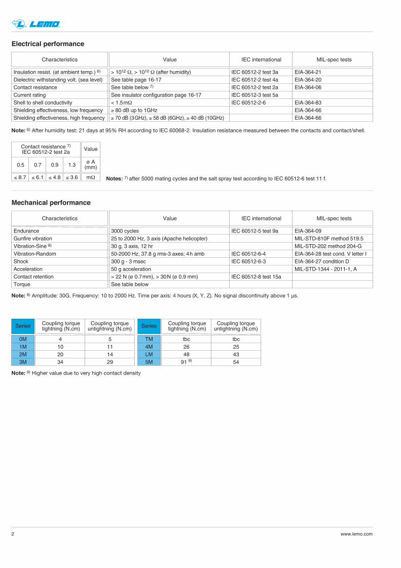
Crimp contacts for plugs, free or fixed sockets
Ref.
CBD
Contact type
Male crimp (fig. 1)Male crimp (fig. 2)Male straight print
Ref.
MPN
Contact type
Female crimp (fig. 1)Female crimp (fig. 2)Female straight print
Dimension of crimp barrels
ø A
ø A
ø C
ø C
Fig. 1 ø A ø C
ø A ø C
Fig. 2
There are 2 forms of crimp barrels:– per fig. 1, the standard design– per fig. 2, with reduced crimp barrel for small conductors.
Contacts
Type
302-303
304-305
0M
Conductor
AWG Section (mm2)min. max. min. max.
24 20 0.204 0.61626 22 0.128 0.38226 22 0.128 0.38232 28 0.032 0.092
305
307-308
1M24 20 0.204 0.61626 22 0.128 0.38226 22 0.128 0.38232 28 0.032 0.092
308-310
312-319
2M24 20 0.204 0.61626 22 0.128 0.38226 22 0.128 0.38232 28 0.032 0.092
322-3303M26 22 0.128 0.38232 28 0.032 0.092
325
340
TM24 20 0.204 0.61626 22 0.128 0.38226 22 0.128 0.38232 28 0.032 0.092
340-3484M26 22 0.128 0.38232 28 0.032 0.092
355
368
LM24 20 0.204 0.61626 22 0.128 0.38226 22 0.128 0.38232 28 0.032 0.092
366
114
5M24 20 0.204 0.61626 22 0.128 0.38226 22 0.128 0.38232 28 0.032 0.092
Ref. contact type
Male Female
Contact
ø A ø C Form(mm) (mm) per fig.
0.9 1.10 10.9 0.87 20.7 0.87 10.7 0.44 2
C MB PC MB P
0.9 1.10 10.9 0.87 20.7 0.87 10.7 0.44 2
C MB PC MB P
0.9 1.10 10.9 0.87 20.7 0.87 10.7 0.44 2
C MB PC MB P
0.9 1.10 10.9 0.87 20.7 0.87 10.7 0.44 2
C MB PC MB P
0.9 1.10 10.9 0.87 20.7 0.87 10.7 0.44 2
C MB PC MB P
0.9 1.10 10.9 0.87 20.7 0.87 10.7 0.44 2
C MB PC MB P
0.7 0.87 10.7 0.44 2
C MB P
0.7 0.87 10.7 0.44 2
C MB P
Note: according to IEC 60352-2 standard, it is strongly not recommended to crimp monostrand cables.
FGN.0M.560.ZZC EGN.0M.660.ZZMFGN.0M.561.ZZC EGN.0M.661.ZZMFGN.0M.555.ZZC EGN.0M.655.ZZMFGN.0M.556.ZZC EGN.0M.656.ZZM
FGN.0M.560.ZZC EGN.0M.660.ZZMFGN.0M.561.ZZC EGN.0M.661.ZZMFGN.0M.555.ZZC EGN.0M.655.ZZMFGN.0M.556.ZZC EGN.0M.656.ZZM
FGN.0M.560.ZZC EGN.0M.660.ZZMFGN.0M.561.ZZC EGN.0M.661.ZZMFGN.0M.555.ZZC EGN.0M.655.ZZMFGN.0M.556.ZZC EGN.0M.656.ZZM
FGN.0M.560.ZZC EGW.TM.660.ZZMFGN.0M.561.ZZC EGW.TM.661.ZZMFGN.0M.555.ZZC EGW.TM.655.ZZMFGN.0M.556.ZZC EGW.TM.656.ZZM
FGN.0M.560.ZZC EGW.TM.660.ZZMFGN.0M.561.ZZC EGW.TM.661.ZZMFGN.0M.555.ZZC EGW.TM.655.ZZMFGN.0M.556.ZZC EGW.TM.656.ZZM
FGN.0M.560.ZZC EGW.TM.660.ZZMFGN.0M.561.ZZC EGW.TM.661.ZZMFGN.0M.555.ZZC EGW.TM.655.ZZMFGN.0M.556.ZZC EGW.TM.656.ZZM
FGN.0M.555.ZZC EGN.0M.655.ZZMFGN.0M.556.ZZC EGN.0M.656.ZZM
FGN.0M.555.ZZC EGW.TM.655.ZZMFGN.0M.556.ZZC EGW.TM.656.ZZM
Part number
For male contacts For female contacts

19www.lemo.com
® ®
Blanking caps for plugsBMF
Part number
BMF.0M.100.•AVBMF.1M.100.•AVBMF.2M.100.•AVBMF.3M.100.•AVBMF.TM.100.•AV BMF.4M.100.•AV BMF.LM.100.•AVBMF.5M.100.•AV
Dimensions (mm)A C L N P X
13.1 12.7 24.6 85.0 5.3 6.014.6 14.2 24.6 85.0 5.3 6.017.6 17.2 24.6 85.0 5.3 6.019.6 19.2 24.6 120.0 5.3 6.022.5 22.0 31.1 120.0 7.9 10.025.0 24.5 31.1 120.0 7.9 10.028.5 28.0 31.1 150.0 7.9 10.034.0 33.5 31.1 150.0 7.9 10.0
Note: this cap is suitable for use with any alignment key configuration.The position «•» of the part number indicates the housing material.See page 17.
sliding loop
L
X
N
P
ø C
ø A
sliding loop
L
X
N
P
ø C
ø A
Blanking caps for plugsBGF
Part number
BGF.0M.100.•AVBGF.1M.100.•AVBGF.2M.100.•AVBGF.3M.100.•AVBGF.TM.100.•AV BGF.4M.100.•AV BGF.LM.100.•AVBGF.5M.100.•AV
Dimensions (mm)A C L N P X
14.4 12.7 24.6 85.0 5.3 6.015.9 14.2 24.6 85.0 5.3 6.018.9 17.2 24.6 85.0 5.3 6.020.9 19.2 24.6 120.0 5.3 6.023.4 22.0 31.1 120.0 7.9 10.025.9 24.5 31.1 120.0 7.9 10.029.4 28.0 31.1 150.0 7.9 10.034.9 33.5 31.1 150.0 7.9 10.0
Note: this cap is suitable for use with any alignment key configuration.The position «•» of the part number indicates the housing material.See page 17.
Accessories
L
X P
ø C
ø A
N
ø 3.5
Blanking caps for fixed socketsBME
Part number
BME.0M.200.•AZBME.1M.200.•AZBME.2M.200.•AZBME.3M.200.•AZBME.TM.200.•AZ BME.4M.200.•AZ BME.LM.200.•AZBME.5M.200.•AZ
Dimensions (mm)A C L N P X
13.1 12.7 23.4 85.0 3.9 6.014.6 14.2 23.4 85.0 3.9 6.017.6 17.2 23.4 85.0 3.9 6.019.6 19.2 23.4 120.0 3.9 6.022.5 22.0 31.0 120.0 3.4 10.025.0 24.5 31.0 120.0 3.4 10.028.5 28.0 31.0 150.0 3.4 10.034.0 33.5 31.0 150.0 3.4 10.0
Note: this cap is suitable for use with any alignment key configuration.The position «•» of the part number indicates the housing material.See page 17.

20 www.lemo.com
® ®
sliding loop
L
X
N
P
ø C
ø A
L
X P
ø C
ø A
N
ø 3.5
Blanking caps for free socketsBGF
Part number
BGF.0M.200.•AZBGF.1M.200.•AZBGF.2M.200.•AZBGF.3M.200.•AZBGF.TM.200.•AZ BGF.4M.200.•AZ BGF.LM.200.•AZBGF.5M.200.•AZ
Dimensions (mm)A C L N P X
14.4 12.7 23.4 85.0 3.9 6.015.9 14.2 23.4 85.0 3.9 6.018.9 17.2 23.4 85.0 3.9 6.020.9 19.2 23.4 120.0 3.9 6.023.4 22.0 31.0 120.0 3.4 10.025.9 24.5 31.0 120.0 3.4 10.029.4 28.0 31.0 150.0 3.4 10.034.9 33.5 31.0 150.0 3.4 10.0
Note: this cap is suitable for use with any alignment key configuration.The position «•» of the part number indicates the housing material.See page 17.
Blanking caps for fixed socketsBGE
Part number
BGE.0M.200.•AZBGE.1M.200.•AZBGE.2M.200.•AZBGE.3M.200.•AZBGE.TM.200.•AZ BGE.4M.200.•AZ BGE.LM.200.•AZBGE.5M.200.•AZ
Dimensions (mm)A C L N P X
14.4 12.7 23.4 85.0 3.9 6.015.9 14.2 23.4 85.0 3.9 6.018.9 17.2 23.4 85.0 3.9 6.020.9 19.2 23.4 120.0 3.9 6.023.4 22.0 31.0 120.0 3.4 10.025.9 24.5 31.0 120.0 3.4 10.029.4 28.0 31.0 150.0 3.4 10.034.9 33.5 31.0 150.0 3.4 10.0
Note: this cap is suitable for use with any alignment key configuration.The position «•» of the part number indicates the housing material.See page 17.
Blanking caps for free socketsBMF
Part number
BMF.0M.200.•AZBMF.1M.200.•AZBMF.2M.200.•AZBMF.3M.200.•AZBMF.TM.200.•AZ BMF.4M.200.•AZ BMF.LM.200.•AZBMF.5M.200.•AZ
Dimensions (mm)A C L N P X
13.1 12.7 23.4 85.0 3.9 6.014.6 14.2 23.4 85.0 3.9 6.017.6 17.2 23.4 85.0 3.9 6.019.6 19.2 23.4 120.0 3.9 6.022.5 22.0 31.0 120.0 3.4 10.025.0 24.5 31.0 120.0 3.4 10.028.5 28.0 31.0 150.0 3.4 10.034.0 33.5 31.0 150.0 3.4 10.0
Note: this cap is suitable for use with any alignment key configuration.The position «•» of the part number indicates the housing material.See page 17.
sliding loop
L
X
N
P
ø C
ø A

GEA.0S.240.RLGEA.1M.240.RLGEA.0E.240.RLGEA.1E.240.RLGEA.3S.240.RLGEA.4M.240.RLGEA.3E.240.RLGEA.5M.240.RL
21www.lemo.com
® ®
Hexagonal nuts for EG● model
e L
A
øB
Part number
● Material: Nickel-plated aluminium alloy (anthracite colour)
GEA
Dimensions (mm)Series
A B e L
0M 11 12.4 M9x0.60 2.01M 13 14.5 M11x1.00 2.52M 17 19.2 M14x1.00 2.53M 19 21.5 M16x1.00 3.0TM 22 25.0 M18x1.00 3.04M 25 28.0 M21x1.00 4.0LM 30 34.0 M24x1.00 5.05M 36 40.5 M30x1.00 5.0
Conical nut for models HE ●, EC●, PE ●
A
e L
ø B
Part number
GEC.0M.240.RNGEC.0E.240.RNGEC.2M.240.RNGEC.3M.240.RNGEC.TM.240.RNGEC.4M.240.RNGEC.LM.240.RNGEC.5M.240.RN
● Material: Nickel-plated aluminium alloy (anthracite colour)
GEC
Dimensions (mm)Series
A B e L
0M 14 17 M13x0.75 3.21M 16 18 M14x1.00 3.02M 18 21 M17x1.00 3.23M 20 23 M19x1.00 3.2TM 23 27 M22x1.00 5.04M 25 29 M24x1.00 5.0LM 29 33 M28x1.00 5.05M 34 38 M33x1.00 5.0
Raychem®AFTER HEATING
BEFORE HEATING
Heatshrink bootStraight boot
Note: request modified elastomer resistant to fluids with hot melt sealant.
AFTER HEATING
BEFORE HEATING
Supplier
Elbow boot
0M-2M 3.82M-4M 5.34M-5M 7.4
Cable ømin.(mm)
Part number
Straight Elbow 90°
202A111-25/86 222A111-25/86202A121-25/86 222A121-25/86202A142-25/86 222A142-25/86
Series
Hexagonal nuts for EC● model
e L
A
øB
GEA
Dimensions (mm)Series
A B e LPart number
GEA.0M.241.RLGEA.0E.240.RLGEA.2M.241.RLGEA.3M.241.RLGEA.TM.241.RLGEA.4M.241.RLGEA.LM.241.RLGEA.5M.241.RL
● Material: Nickel-plated aluminium alloy (anthracite colour)
0M 16 18.2 M13x0.75 2.51M 17 19.2 M14x1.00 2.52M 19 21.5 M17x1.00 3.03M 25 22.0 M19x1.00 3.0TM 25 28.0 M22x1.00 3.04M 30 34.0 M24x1.00 3.0LM 32 36.0 M28x1.00 3.05M 37 41.0 M33x1.00 3.0
22 www.lemo.com
® ®
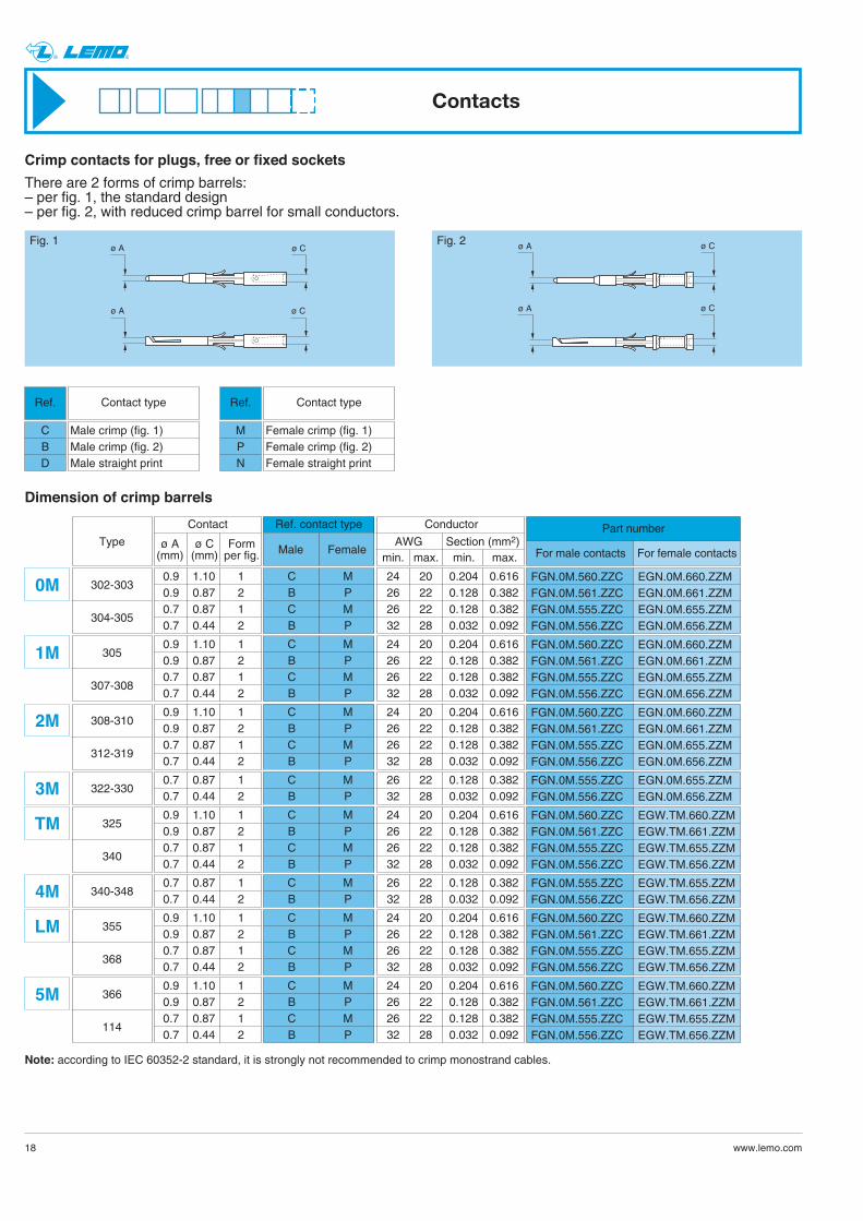
These positioners are suitable for use with both manual andpneumatic crimping tools according to the MIL-C-22520/7-01 stan-dard.
Positioners for crimp contactsDCE
male female
Type
302-303
304-305
0M
305
307-308
1M
308-310
312-319
2M
322-3303M
325
340
TM
340-3484M
355
368
LM
366
114
5M
DCE.91.090.5MVC DCE.91.090.3MVM
DCE.91.070.5MVC DCE.91.070.3MVM
DCE.91.090.5MVC DCE.91.090.3MVM
DCE.91.070.5MVC DCE.91.070.3MVM
DCE.91.090.5MVC DCE.91.090.3MVM
DCE.91.070.5MVC DCE.91.070.3MVM
DCE.91.090.5MVC DCE.91.09T.5MVM
DCE.91.070.5MVC DCE.91.07T.5MVM
DCE.91.090.5MVC DCE.91.09T.5MVM
DCE.91.070.5MVC DCE.91.07T.5MVM
DCE.91.090.5MVC DCE.91.09T.5MVM
DCE.91.070.5MVC DCE.91.07T.5MVM
DCE.91.070.5MVC DCE.91.070.3MVM
DCE.91.070.5MVC DCE.91.07T.5MVM
Positioners part number
For male contacts For female contacts
Contact
ø A ø C Form(mm) (mm) per fig.
0.9 1.10 10.9 0.87 20.7 0.87 10.7 0.44 2
0.9 1.10 10.9 0.87 20.7 0.87 10.7 0.44 2
0.9 1.10 10.9 0.87 20.7 0.87 10.7 0.44 2
0.9 1.10 10.9 0.87 20.7 0.87 10.7 0.44 2
0.9 1.10 10.9 0.87 20.7 0.87 10.7 0.44 2
0.9 1.10 10.9 0.87 20.7 0.87 10.7 0.44 2
0.7 0.87 10.7 0.44 2
0.7 0.87 10.7 0.44 2
ø A
ø A
ø C
ø C
Fig. 1
ø A ø C
ø A ø C
Fig. 2
Note: a wide variation of strand number and diameter combinations are quoted as being AWG, some of which do not have a large enough cross sectionto guarantee a crimp as per either MIL-C-22520/1-01 or /7-01. Our technical department is at your disposal to study and propose a solution to all your applications.
Tooling
Extractors for crimp contactsDCF
Part number
DCF.93.090.4LTDCF.93.070.4LT
Contactø
0.90.7
Note: this model is used for male and female contacts.
23www.lemo.com
® ®
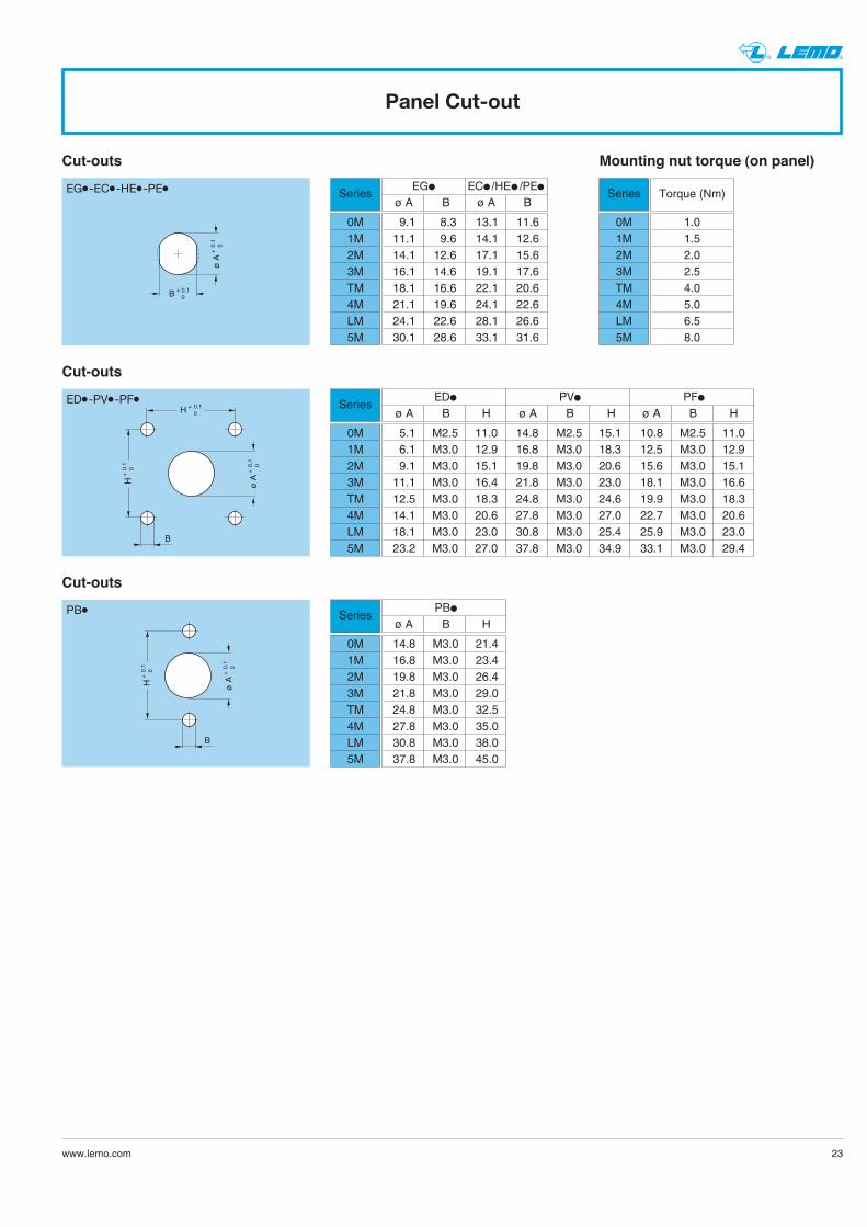
Cut-outs
Series
0M1M2M3MTM4MLM5M
Torque (Nm)
1.01.52.02.54.05.06.58.0
Mounting nut torque (on panel)
B + 0.1 0
ø A
+ 0.
1
0
EG●-EC●-HE●-PE●
ø A
+ 0
.1
0
H +
0.1
0
H + 0.1
0
B
ED●-PV●-PF●
ø A
+ 0
.1
0
H +
0.1
0
B
PB●
Panel Cut-out
Series
0M1M2M3MTM4MLM5M
EG● EC● /HE● /PE●
ø A B ø A B
9.1 8.3 13.1 11.611.1 9.6 14.1 12.614.1 12.6 17.1 15.616.1 14.6 19.1 17.618.1 16.6 22.1 20.621.1 19.6 24.1 22.624.1 22.6 28.1 26.630.1 28.6 33.1 31.6
Cut-outs
Series
0M1M2M3MTM4MLM5M
ED● PV● PF●
ø A B H ø A B H ø A B H
5.1 M2.5 11.0 14.8 M2.5 15.1 10.8 M2.5 11.06.1 M3.0 12.9 16.8 M3.0 18.3 12.5 M3.0 12.99.1 M3.0 15.1 19.8 M3.0 20.6 15.6 M3.0 15.111.1 M3.0 16.4 21.8 M3.0 23.0 18.1 M3.0 16.612.5 M3.0 18.3 24.8 M3.0 24.6 19.9 M3.0 18.314.1 M3.0 20.6 27.8 M3.0 27.0 22.7 M3.0 20.618.1 M3.0 23.0 30.8 M3.0 25.4 25.9 M3.0 23.023.2 M3.0 27.0 37.8 M3.0 34.9 33.1 M3.0 29.4
Cut-outs
Series
0M1M2M3MTM4MLM5M
PB●
ø A B H
14.8 M3.0 21.416.8 M3.0 23.419.8 M3.0 26.421.8 M3.0 29.024.8 M3.0 32.527.8 M3.0 35.030.8 M3.0 38.037.8 M3.0 45.0

® ®
www.lemo.com 24
4 x ø 1 +0.1 0
2 x ø 0.8 +0.1 0
ø 2
.2 5.08
0M.3024 x ø 1 +0.1 0
3 x ø 0.8 +0.1 0
ø 2
.3
120° 5.
08
0M.3034 x ø 1 +0.1 0
4 x ø 0.8 +0.1 0
90° ø
2.545°
5.08
0M.3044 x ø 1 +0.1 0
5 x ø 0.8 +0.1 0
72°
ø 2
.8 5.08
0M.305
4 x ø 1 +0.1 0
5 x ø 0.8 +0.1 0
72°
ø 3
.4 7.62
1M.3054 x ø 1 +0.1 0
7 x ø 0.8 +0.1 0
ø 3
.7
60°
30°
7.62
1M.307
ø 3
.8
8 x ø 0.8 +0.1 0
51°26' 4 x ø 1 +0.1 0
7.62
1M.3084 x ø 1 +0.1 0
8 x ø 0.8 +0.1 0
ø 6
.4
45°
8.89
2M.308
4 x ø 1 +0.1 0
10 x ø 0.8 +0.1 0
ø 6.
2
ø 2.
1545°
22°30'
8.89
2M.310
ø 2
.8
ø 6
.5
12 x ø 0.8 +0.1 0
90°
45°
45° 22°30' 4 x ø 1 +0.1 0
8.89
2M.312
ø 3
.5
ø 6
.7
30°60°
19 x ø 0.8 +0.1 0
15° 4 x ø 1 +0.1 0
8.89
2M.319
PCB drilling pattern
48 x ø 0.8 +0.1 0
ø 1
1.9
24°
ø 5
.2
ø 8
.5
ø 1
.9
22°30'
8°10'55''
12°
45
°
4 x ø 1 +0.1 0
13.9
7
16°2
1'49''
120°
25 x ø 0.8 +0.1 0
ø 9
.8
ø 5
.8
24°40°
4 x ø 1 +0.1 0
12.7
TM.325
4M.348
36°
30 x ø 0.8 +0.1 0
2.2
ø 5
.7
2.6
11°15'
ø 9
22°3
0'
4 x ø 1 +0.1 0
10.1
6
3M.330
45°
22 x ø 0.8 +0.1 0
22°30'
ø 5
ø 8
.8
12°52'
25°4
3'
4 x ø 1 +0.1 0
10.1
6
3M.322
40 x ø 0.8 +0.1 0
ø 1
1.64
51°26'
18°
9°
ø 4
.24
ø 7
.94
4 x ø 1 +0.1 0
13.9
727°4
1'32
''
4M.340
40 x ø 0.8 +0.1 0
ø 1
0.2
60°
18°
9°
ø 3
.4
ø 6
.8
4 x ø 1 +0.1 0
12.7
27°4
1'32
''
TM.340
4 x ø 1 +0.1 0
For HE● models For EG● , EC● and ED● models
Fixed socket with straight print contact

www.lemo.com
® ®
4 x ø 1 +0.1 06°55'30''
66 x ø 0.8 +0.1 0
ø 5
.6
ø 1
0.08
27°41'30''
18°57'
ø14
.96
ø19
.84
13°51'
51°26' 20
.32
4 x ø 1 +0.1 0
114 x ø 0.8 + 0.1 0
5°
6°12’25’’10°
40°
ø 9
.9
ø 6
.3
ø 1
3.5
ø 1
7.1
8°10’55’’
120°
20.3
2
20.7
24°
ø 2
.7
12°24’50’’
16°2
1’49’’
5M.366 5M.114
4 x ø 1 +0.1 0
55 x ø 0.8 +0.1 0
ø 2
.8
10°35’18’’
18°
ø 6
.9
ø11
.1
ø15
.3
16.5
1
7°30’
21°1
0’35’’
36°
15°
LM.355
4 x ø 1 +0.1 0
68 x ø 0.8 +0.1 0
ø 4
.25
13°51’
51°25’30’’
ø 8
ø11
.75
ø15
.5
16.5
1
9°
6°40’
27°4
1’30
’’
18°
13°20’
LM.368
25

26 www.lemo.com
® ®
Assembly instructions for plugs and sockets
2
2 1
1
FG●
PH●
PB●
1. Cable preparation
First place the heatshrink boot ➀ overthe cable. Strip the cable accor dingto dimensions of the table, then widenthe shield.
2. Cable termination
2.1 With shielded cables, widen and pull the shield all the way to the back.Fix the appropriate positioner onto the crimping tool and set the selec-tor to the number corresponding to the AWG of the conductor used asindicated on the positioner label. Fit the conductor into the contact ➁; make sure it is visible through thecontact’s inspection hole.Slide the conductor-contact assembly into the open crimping tool; makesure that the contact is pushed fully into the positioner. Close the tool. Remove from crimping tool and check that conductor is secure incontact and shows in inspection hole.
2.2 Arrange the conductor-contact assemblies according to the markings,into the rear cable seal. Push them deeply into the insulator, using tweezers if necessary;check that all the contacts are correctly located in the insulator: 1)by verifying the alignment of the contacts at the front of the insulatorand 2) by gently pulling on each conductor. Verification should also be made using the appropriate retention tes-ting tool.
2.3 Bring the shield around the rear of connector. Secure it with a band-it tie-wrap (not furnished) to fix the shield in place.Cut off the possible shield surplus.
2.4 Put the heatshrink boot in place and heat gently until it retracts.
Series L S T
0M to 5M 20 15 3.51T ± 0.2
L ± 0.5
S ± 0.5
Crimp2
Crimp2
Steel tie-wrap band (~3 mm wide)
Steel tie-wrap band (~3 mm wide)
Heat Heat
Note: dimensions are in mm.

27www.lemo.com
® ®
Assembly instructions for plugs and sockets (with optional mold stop)
1
1
FG●
PH●
PB●
T ± 0.2
L ± 0.5
S ± 0.5
Crimp1
Crimp1
Steel tie-wrap band (~3 mm wide)
Steel tie-wrap band (~3 mm wide)
Overmolding
Overmolding
1. Cable preparation
Strip the cable accor ding to dimen-sions of the table, then widen the shield.
2. Cable termination
2.1 With shielded cables, widen and pull the shield all the way to the back.Fix the appropriate positioner onto the crimping tool and set the selec-tor to the number corresponding to the AWG of the conductor used asindicated on the positioner label. Fit the conductor into the contact ➀; make sure it is visible through thecontact’s inspection hole.Slide the conductor-contact assembly into the open crimping tool; makesure that the contact is pushed fully into the positioner. Close the tool. Remove from crimping tool and check that conductor is secure incontact and shows in inspection hole.
2.2 Arrange the conductor-contact assemblies according to the markings,into the rear cable seal. Push them deeply into the insulator, using tweezers if necessary;check that all the contacts are correctly located in the insulator: 1)by verifying the alignment of the contacts at the front of the insulatorand 2) by gently pulling on each conductor. Verification should also be made using the appropriate retention tes-ting tool.
2.3 Bring the shield around the rear of connector until the mold stop. Secure it with a band-it tie-wrap (not furnished) to fix the shield in place.Cut off the possible shield surplus.
2.4 Custom overmold cable assembly.
Series L S T
0M to 5M 20 15 3.5
Note: dimensions are in mm.

28 www.lemo.com
® ®
Notes

29www.lemo.com
® ®
Data subject to change
PLEASE READ AND FOLLOW ALL INSTUCTIONS CAREFULLY AND CONSULT ALL RELEVENT NATIONAL ANDINTERNATIONAL SAFETY REGULATIONS FOR YOUR APPLICATION.IMPROPER HANDLING, CABLE ASSEMBLY, OR WRONG USE OF CONNECTORS CAN RESULT IN HAZARDOUSSITUATIONS.
1. SHOCK AND FIRE HAZARDIncorrect wiring, the use of damaged components, presence of foreign objects (such as metal debris), and / or residue (such as cleaning fluids), can result in short circuits, overheating, and / or risk of electric shock.Mated components should never be disconnected while live as this may result in an exposed electric arc and local overheating, resulting in possible damage to components.
2. HANDLINGConnectors and their components should be visually inspected for damage prior to installation and assembly. Suspect components should be rejected or returned to the factory for verification.Connector assembly and installation should only be carried out by properly trained personnel. Proper tools must be usedduring installation and / or assembly in order to obtain safe and reliable performance.
3. USEConnectors with exposed contacts should never be live (or on the current supply side of a circuit). Under general conditions voltages above 30 VAC and 42 VDC are considered hazardous and proper measures should be taken to eliminate all risk of transmission of such voltages to any exposed metal part of the connector.
4. TEST AND OPERATING VOLTAGESThe maximum admissible operating voltage depends upon the national or international standards in force for the application in question. Air and creepage distances impact the operating voltage; reference values are indicated in the catalog however these may be influenced by PC board design and / or wiring harnesses.The test voltage indicated in the catalog is 75% of the mean breakdown voltage; the test is applied at 500 V/s and the test duration is 1 minute.
5. CE MARKINGCE marking means that the appliance or equipment bearing it complies with the protection requirements of one orseveral European safety directives.CE marking applies to complete products or equipment, but not to electromechanical components, such asconnectors.
6. PRODUCT IMPROVEMENTSThe LEMO Group reserves the right to modify and improve to our products or specifications without providing prior notification.
Product safety notice
No reproduction or use without express permission of editorial or pictorial content, in any manner.LEMO reserve the right at all times to modify and improve specifications without any notification.

LEMO HEADQUARTERSSWITZERLANDLEMO SA Chemin des Champs-Courbes 28 - P.O. Box 194 - CH-1024 EcublensTel. (+41 21) 695 16 00 - Fax (+41 21) 695 16 02 - e-mail: [email protected]
LEMO SUBSIDIARIES
© CAT.M
M.LEN.P0811 - Updated February 2012
LEMO DISTRIBUTORSAUSTRALIA, BRAZIL, CANADA, CZECH REPUBLIC, GREECE, INDIA, ISRAEL, NEW ZEALAND, PAKISTAN, POLAND, RUSSIA, SOUTH AFRICA, SOUTH KOREA,TAIWAN, TURKEY, UKRAINE
www.lemo.com
AUSTRIALEMO Elektronik GesmbHLemböckgasse 49/E6-31230 WienTel: (+43 1) 914 23 20 0Fax:(+43 1) 914 23 20 [email protected]
CHINALEMO Trading (Shanghai) Co., LtdLEMO Electronics (Shanghai) Co., Ltd 5th Floor, Block 6, City of ELITE,1000 Jinhai Road, PudongShanghai, China 201206Tel: (+86 21) 5899 7721Fax: (+86 21) 5899 [email protected]
DENMARKLEMO Denmark A/SGammel Mosevej 462820 GentofteTel: (+45) 45 20 44 00Fax: (+45) 45 20 44 [email protected]
FRANCELEMO France Sàrl24/28 Avenue Graham BellBâtiment Balthus 4Bussy Saint Georges77607 Marne la Vallée Cedex 3Tel: (+33 1) 60 94 60 94Fax: (+33 1) 60 94 60 [email protected]
GERMANYLEMO Elektronik GmbHHanns-Schwindt-Str. 681829 München Tel: (+49 89) 42 77 03Fax: (+49 89) 420 21 [email protected]
HONG KONGLEMO Hong Kong LtdUnit 1207, 12/F, Corporation Square,8 Lam Lok Street, Kowloon Bay,Kowloon - Hong KongTel: (+852) 2174 0468Fax: (+852) 2174 [email protected]
HUNGARYREDEL Elektronika KftNagysándor József u. 6-121201 BudapestTel: (+36 1) 421 47 10Fax: (+36 1) 421 47 [email protected]
ITALYLEMO Italia srlViale Lunigiana 2520125 MilanoTel: (+39 02) 66 71 10 46Fax: (+39 02) 66 71 10 [email protected]
JAPANLEMO Japan Ltd4-10-3, Takaido Higashi, Suginami-ku, Tokyo, 168-0072Tel: (+81 3) 53 44 39 33Fax: (+81 3) 53 44 39 [email protected]
NETHERLANDS / BELGIUMLEMO Connectors BeneluxDe Trompet 10601967 DD HeemskerkTel. (+31) 251 25 78 20Fax (+31) 251 25 78 [email protected]
NORWAY / ICELANDLEMO Norway A/SStanseveien 6B0975 OsloTel: (+47) 22 91 70 40Fax: (+47) 22 91 70 [email protected]
SINGAPORELEMO Asia Pte Ltd4 Leng Kee Road, #06-09 SiS Building Singapore 159088Tel: (+65) 6476 0672Fax: (+65) 6474 [email protected]
SPAIN / PORTUGALIBERLEMO S.A.Brasil, 45, 08402 GranollersBarcelonaTel: (+34 93) 860 44 20Fax: (+34 93) 879 10 [email protected]
Madrid OfficeAntonio López, 96, 28019 MadridTel: (+34 91) 469 99 19Fax: (+34 91) 469 99 59
SWEDEN / FINLANDLEMO Nordic ABMariehällsvägen 39A 168 65 BrommaTel: (+46 8) 635 60 60Fax: (+46 8) 635 60 [email protected]
SWITZERLANDLEMO Verkauf AGGrundstrasse 22 B6343 RotkreuzTel: (+41 41) 790 49 40Fax: (+41 41) 790 49 [email protected]
UNITED KINGDOMLEMO UK Ltd12-20 North StreetWorthingWest Sussex, BN11 1DUTel: (+44 1903) 23 45 43Fax: (+44 1903) 20 62 [email protected]
USALEMO USA IncP.O. Box 2408Rohnert Park, CA 94927-2408Tel: (+1 707) 578 88 11(+1 800) 444 53 66Fax:(+1 707) 578 08 [email protected]


![Catalogue A30.en // Series SB - Circular connectors for special … · 2016. 8. 23. · max testing time [days]) -25/60/21 Mechanical endurance (IEC 60512-5, test 9a) 2,000 : mating](https://img.pdfslide.net/doc/110x75/603290087993c142582cf399/catalogue-a30en-series-sb-circular-connectors-for-special-2016-8-23-max.jpg)