Embed Size (px)
Citation preview
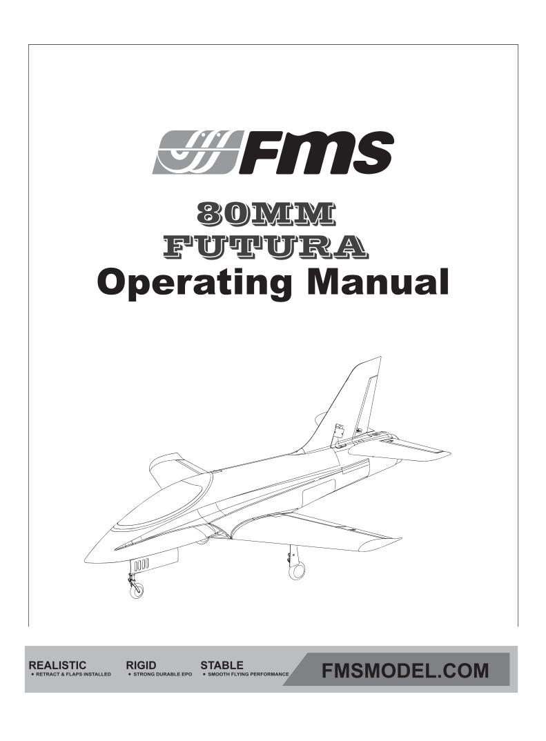
80MM FUTURA
REALISTIC RIGIDRETRACT & FLAPS INSTALLED STRONG DURABLE EPO
STABLESMOOTH FLYING PERFORMANCE FMSMODEL.COM

As the user of this product, you are solely responsible for operating in a manner that does not endanger yourself andothers or result in damage to the product or the property of others. This model is controlled by a radio signal subjectto interference from many sources outside your control. This interference can cause momentary loss of control so itis advisable to always keep a safe distance in all directions around your model, as this margin will help avoid collisionsor injury.Age Recommendation: Not for children under 14 years. This is not a toy.·Never operate your model with low transmitter batteries.·Always operate your model in an open area away from cars, traffic or people.·Avoid operating your model in the street where injury or damage can occur.·Never operate the model in populated areas for any reason.·Carefully follow the directions and warnings for this and any optional support equipment you use (chargers, rechargeable battery packs, etc.)·Keep all chemicals, small parts and anything electrical out of the reach of children.·Moisture causes damage to electronics. Avoid water exposure to all equipment not specifically designed and protected for this purpose.·Never lick or any place of any your model in your mouth as it could cause serious injury or even death.
Lithium Polymer (Li-Po) Battery WarningCAUTION: Always follow the manufacturer’s instructions for safe use and disposal of batteries. Fire, propertydamage, or serious injury can result from the mishandling of Li-Po batteries.
By handling, charging or using a Li-Po Battery you assume all risks associated with lithium batteries.If at any time the batteries begin to swell or balloon, discontinue use immediately!Always store the batteries at room temperature in a dry area to extend the life of the battery. Always transportor temporarily store the battery in a temperature range of 40-120F. Do not store the battery or model in a car or in direct sunlight. If stored in a hot car, the battery can be damaged or even catch fire.Never use a Ni-Mh Charger to charge Li-Po Batteries. Failure to charge the battery with a Li-Po compatible chargermay cause fire resulting in personal injury and property damage.Never discharge Li-Po Cells below 3V.Never leave charging batteries unattended.Never charge damaged batteries.Charging the Flight Battery WarningUse a battery charger that is designed to safely charge the Li-Po Battery. Read the charger instructions carefully before use. When charging the battery, make certain the battery is on a heat resistant surface. It is also highlyrecommended to place the Li-Po Battery inside a fire resistant charging bag readily available at hobby shops oronline.
WARNING: Read the ENTIRE instruction manual to become familiar with the features of the product before operating. Failure to operate the product correctly can result in damage to the product,personal property and cause serious injury. This is a sophisticated hobby product and NOT a toy. It must be operated with caution and common sense and failure to do so could result in injury or damage to the product or other property. This product is not intended for use by children without direct adult supervision. This manual contains instructions for safety operation and maintenance. It is essential to read and follow all the instructions and warnings in the manual prior to assembly, setup or use, in order to operate and avoid damage or serious injury.
Table of Contents
3
IntroductionsContents of KitModel AssemblyBattery and radio installationImportant ESC and model informationThe transmitter and model setupCheck the control throwsControl Horn and Servo Arm SettingsCenter of Gravity(CG)Before flying the modelFlying CourseTrouble shootingSpare parts list contentESC instruction
··························································································································3························································································································4
······················································································································5·····································································································8
·························································································9································································································9
········································································································10·························································································11
·············································································································12············································································································13
·······················································································································14····················································································································15
··········································································································16······················································································································17
IntroductionsWith the increased interest and development of Electric Ducted Fans (EDF), FMS is proud to announce their 1040 mm (41.7 in) wingspan 80mm EDF version of the famous Futura. This EPO foam version of this quick flying aerobatic jet is another example of the FMS quality. Equipped with our new and improved 80mm fan unit, the Futura is capable of producing 3400 grams of force (7.5 LBF) of thrust. A must have for the pilot that “Feels the need for Speed”.
Key features:
1. Powerful 3270-KV2000 motor2. 80mm 12 Blade Fan unit3. High-quality Predator 100A ESC4. EPO40 foam material5. Digital metal gear servos throughout for better controlling capabilities6. New CNC-processed shock-absorbed metal landing gear set (Worm Dia. 10mm) helps to withstandt those less-than-perfect landings Function Flaps 7. Multi-connector for one-step installation (With the latest multi-connect technology, FMS hass streamlined the wiring system, making it easier to install and eliminating wiring problems.)8. Oversized battery compartment9. Button-type canopy hatch10. No glue required, screw-together construction11. Environmentally friendly water-based paint for better color and gloss
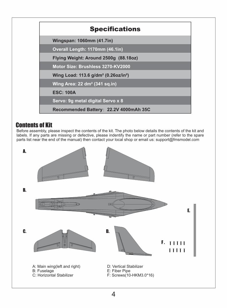
A.
B.
C. D.
F .
E.
A: Main wing(left and right)B: Fuselage C: Horizontal Stabilizer
D: Vertical Stabilizer E: Fiber PipeF: Screws(10-HKM3.0*16)
Before assembly, please inspect the contents of the kit. The photo below details the contents of the kit and labels. If any parts are missing or defective, please indentify the name or part number (refer to the spare parts list near the end of the manual) then contact your local shop or email us: [email protected]
Contents of Kit
4
Wingspan: 1060mm (41.7in)
Overall Length: 1170mm (46.1in)
Flying Weight: Around 2500g (88.18oz)
Motor Size: Brushless 3270-KV2000
Wing Load: 113.6 g/dm² (0.26oz/in²)
Wing Area: 22 dm² (341 sq.in)
ESC: 100A
Recommended Battery:22.2V 4000mAh 35C
Servo: 9g metal digital Servo x 8
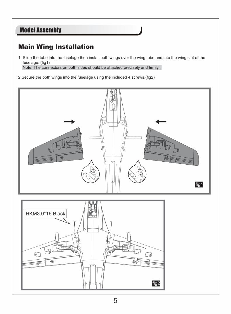
fig1
fig2
5
1. Slide the tube into the fuselage then install both wings over the wing tube and into the wing slot of thefuselage. (fig1)Note: The connectors on both sides should be attached precisely and firmly.
2.Secure the both wings into the fuselage using the included 4 screws.(fig2)
Main Wing Installation
Model Assembly
HKM3.0*16 Black
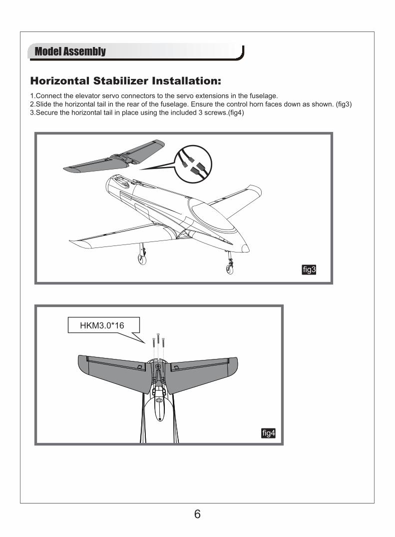
fig4
fig3
6
Horizontal Stabilizer Installation:
Model Assembly
1.Connect the elevator servo connectors to the servo extensions in the fuselage.2.Slide the horizontal tail in the rear of the fuselage. Ensure the control horn faces down as shown. (fig3)3.Secure the horizontal tail in place using the included 3 screws.(fig4)
HKM3.0*16
7
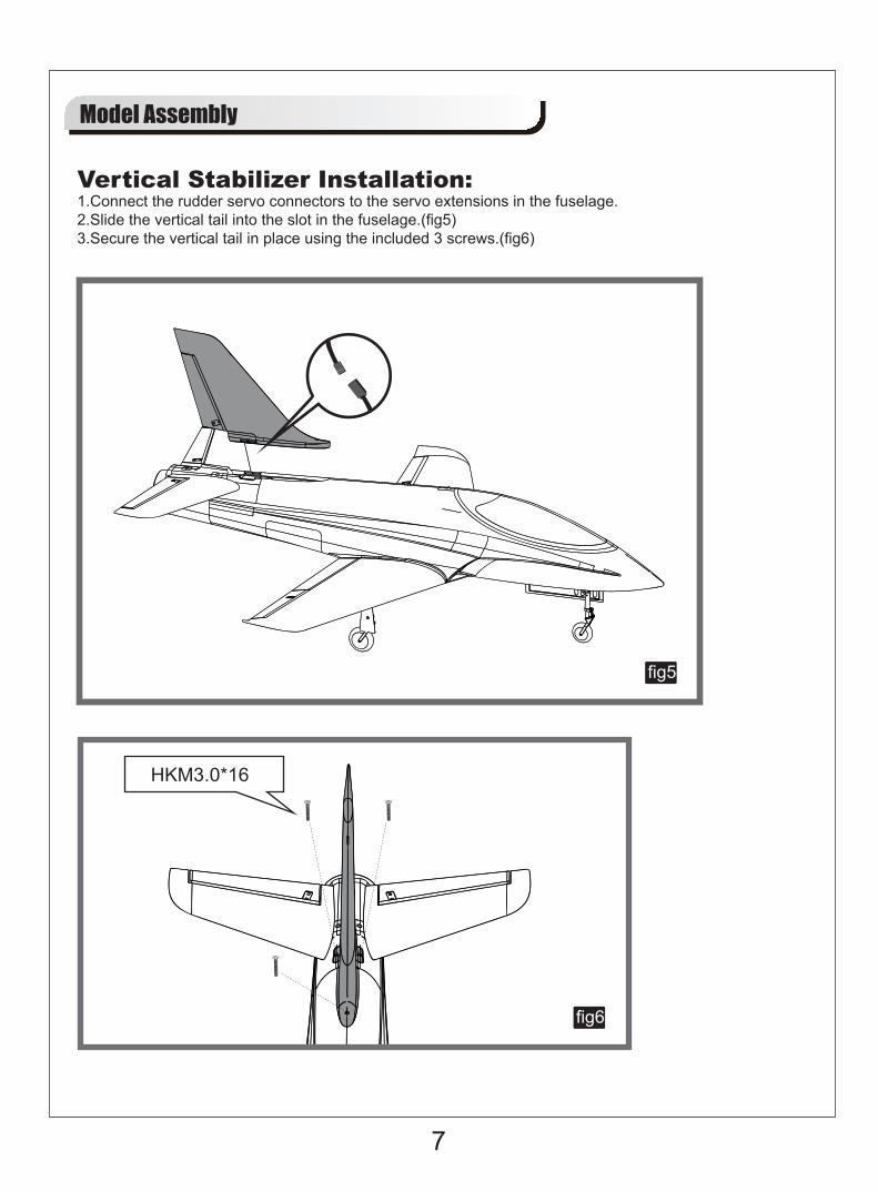
Model Assembly
1.Connect the rudder servo connectors to the servo extensions in the fuselage.2.Slide the vertical tail into the slot in the fuselage.(fig5)3.Secure the vertical tail in place using the included 3 screws.(fig6)
fig5
fig6
Vertical Stabilizer Installation:
HKM3.0*16
Battery and radio installation
8
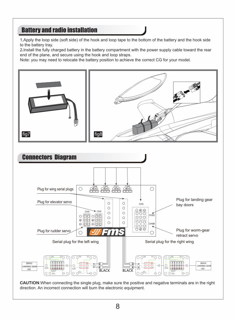
1.Apply the loop side (soft side) of the hook and loop tape to the bottom of the battery and the hook sideto the battery tray.2.Install the fully charged battery in the battery compartment with the power supply cable toward the rearend of the plane, and secure using the hook and loop straps.Note: you may need to relocate the battery position to achieve the correct CG for your model.
fig8fig7
CAUTION:When connecting the single plug, make sure the positive and negative terminals are in the right direction. An incorrect connection will burn the electronic equipment.
Connectors Diagram
S5c
S5b
S6S1
LED
S6 S1
S5cS5b
SERVOLANDING GEAR
LED
SERVO
LANDING GEARLED
S1S6
S5cS5b
S5c
S5b
S6
LED
S1
BLACK BLACK
Get your model ready to fly
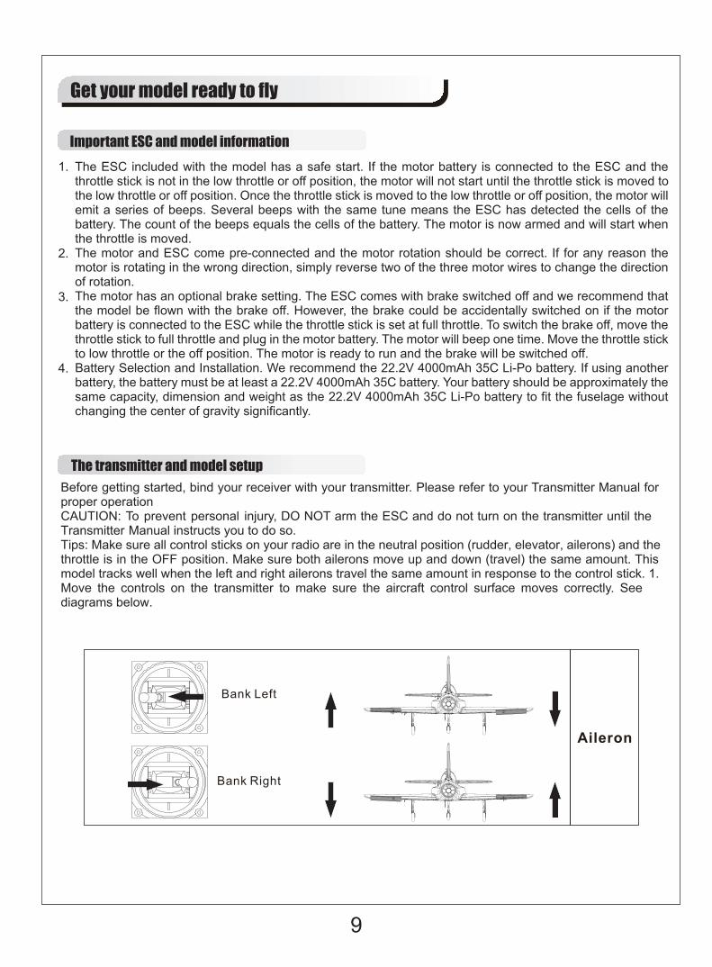
Important ESC and model informationThe ESC included with the model has a safe start. If the motor battery is connected to the ESC and the throttle stick is not in the low throttle or off position, the motor will not start until the throttle stick is moved to the low throttle or off position. Once the throttle stick is moved to the low throttle or off position, the motor will emit a series of beeps. Several beeps with the same tune means the ESC has detected the cells of the battery. The count of the beeps equals the cells of the battery. The motor is now armed and will start when the throttle is moved.The motor and ESC come pre-connected and the motor rotation should be correct. If for any reason the motor is rotating in the wrong direction, simply reverse two of the three motor wires to change the direction of rotation.The motor has an optional brake setting. The ESC comes with brake switched off and we recommend that the model be flown with the brake off. However, the brake could be accidentally switched on if the motor battery is connected to the ESC while the throttle stick is set at full throttle. To switch the brake off, move the throttle stick to full throttle and plug in the motor battery. The motor will beep one time. Move the throttle stick to low throttle or the off position. The motor is ready to run and the brake will be switched off.Battery Selection and Installation. We recommend the 22.2V 4000mAh 35C Li-Po battery. If using another battery, the battery must be at least a 22.2V 4000mAh 35C battery. Your battery should be approximately the same capacity, dimension and weight as the 22.2V 4000mAh 35C Li-Po battery to fit the fuselage without changing the center of gravity significantly.
The transmitter and model setupBefore getting started, bind your receiver with your transmitter. Please refer to your Transmitter Manual for proper operationCAUTION: To prevent personal injury, DO NOT arm the ESC and do not turn on the transmitter until the Transmitter Manual instructs you to do so.Tips: Make sure all control sticks on your radio are in the neutral position (rudder, elevator, ailerons) and the throttle is in the OFF position. Make sure both ailerons move up and down (travel) the same amount. This model tracks well when the left and right ailerons travel the same amount in response to the control stick. 1. Move the controls on the transmitter to make sure the aircraft control surface moves correctly. See diagrams below.
9
1.
2.
3.
4.
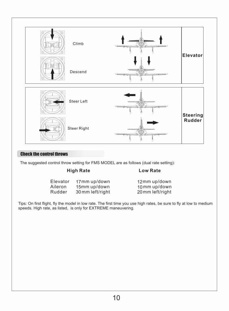
Check the control throwsThe suggested control throw setting for FMS MODEL are as follows (dual rate setting):
Tips: On first flight, fly the model in low rate. The first time you use high rates, be sure to fly at low to mediumspeeds. High rate, as listed, is only for EXTREME maneuvering.
171530 20
1012
10
11
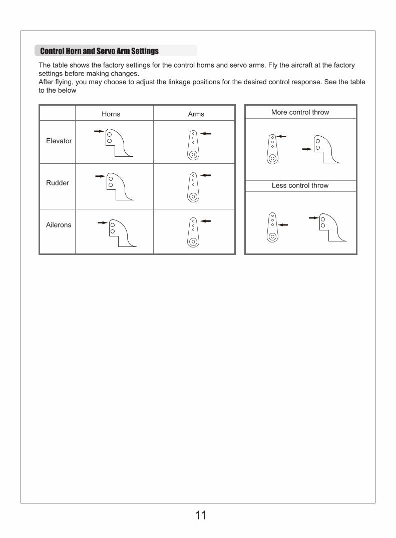
The table shows the factory settings for the control horns and servo arms. Fly the aircraft at the factorysettings before making changes.After flying, you may choose to adjust the linkage positions for the desired control response. See the tableto the below
Control Horn and Servo Arm Settings
More control throw
Less control throw
Elevator
Rudder
Ailerons
Horns Arms
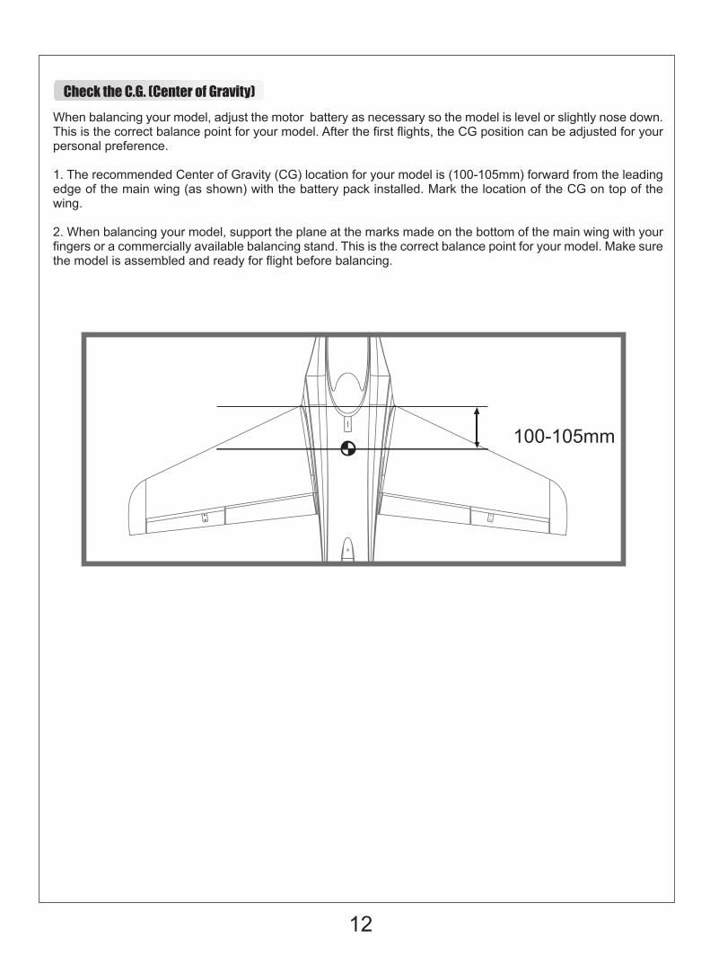
Check the C.G. (Center of Gravity)When balancing your model, adjust the motor battery as necessary so the model is level or slightly nose down. This is the correct balance point for your model. After the first flights, the CG position can be adjusted for your personal preference.
1. The recommended Center of Gravity (CG) location for your model is (100-105mm) forward from the leadingedge of the main wing (as shown) with the battery pack installed. Mark the location of the CG on top of thewing.
2. When balancing your model, support the plane at the marks made on the bottom of the main wing with yourfingers or a commercially available balancing stand. This is the correct balance point for your model. Make surethe model is assembled and ready for flight before balancing.
12
100-105mm
Before flying the model
Find a suitable flying site
Perform the range check for your plane
Monitor your flight time
Find a flying site clear of buildings, trees, power lines and other obstructions. Until you know how much area will be required and have mastered flying your plane in confined spaces, choose a site which is at least the size of two to three football fields - a flying field specifically for R/C planes is best. Never fly near people - especially children, who can wander unpredictably.
As a precaution, an operational ground range test should be performed before the first flight each time you go out. Performing a range test is a good way to detect problems that could cause loss of control such as low batteries, defective or damaged radio components, or radio interference. This usually requires an assistant and should be done at the actual flying site you will be using.
First turn on the transmitter, then install a fully-charged battery into the fuselage. Connect the battery and install the hatch.
Remember, use care not to bump the throttle stick. Otherwise, the propeller/fan will turn and possibly cause damage or injury.
Note: Please refer to your Transmitter Manual that came with your radio control system to perform a ground range check. If the controls are not working correctly or if anything seems wrong, do not fly the model until you correct the problem. Make certain all the servo wires are securely connected to the receiver and the transmitter batteries have a good connection.
Monitor and limit your flight time using a timer (such as on a wristwatch or in your transmitter if available). When the batteries are getting low you will usually notice a performance drop before the ESC cuts off motor power, so when the plane starts flying slower you should land. Often (but not always) power can be briefly restored after the motor cuts off by holding the throttle stick all the way down for a few seconds.To avoid an unexpected dead-stick landing on your first flight, set your timer to a conservative 4 minutes. When your alarm sounds you should land right away.
13
Flying Course
Flying
Take offWhile applying power, slowly steer to keep the model straight. The model should accelerate quickly. As the model gains flight speed you will want to climb at a steady and even rate. It will climb out at a nice angle of attack (AOA).
Always choose a wide-open space for flying your plane. It is ideal for you to fly at a sanctioned flying field. If you are not flying at an approved site always avoid flying near houses, trees, wires and buildings. You should also be careful to avoid flying in areas where there are many people, such as busy parks, schoolyards, or soccer fields. Consult laws and ordinances before choosing a location to fly your aircraft. After takeoff, gain some altitude. Climb to a safe height before trying technical manoeuvres, including high speed passes, inverted flight, loops, and point rolls.
Land the model when you hear the motor pulsing (LVC) or if you notice a reduction in power. If using a transmitter with a timer, set the timer so you have enough flight time to make several landing approaches.Recharge the battery and repair the model as needed .The model’s three point landing gear allows the model to land on hard surfaces. Align model directly into the wind and fly down to the ground. Fly the airplane down to the ground using 1/4-1/3 throttle to keep enough energy for proper flare. Before the model touches down, always fully decrease the throttle to avoid damaging the propeller or other components. The key to a great landing is to manage the power and elevator all the way to the ground and set down lightly on the main landing gear. After a few flights you will find the model can be set down lightly on the mains and you can hold the nose wheel off balancing the model on the mains until it slows and gently settles the nose.
Repairs to the foam should be made with foam safe adhesives such as hot glue, foam safe CA, and 5min epoxy. When parts are not repairable, see the Spare Parts List for ordering by item number.Always check to make sure all screws on the aircraft are tightened. Pay special attention to make sure the spinner is firmly in place before every flight.
Maintenance
Landing
14
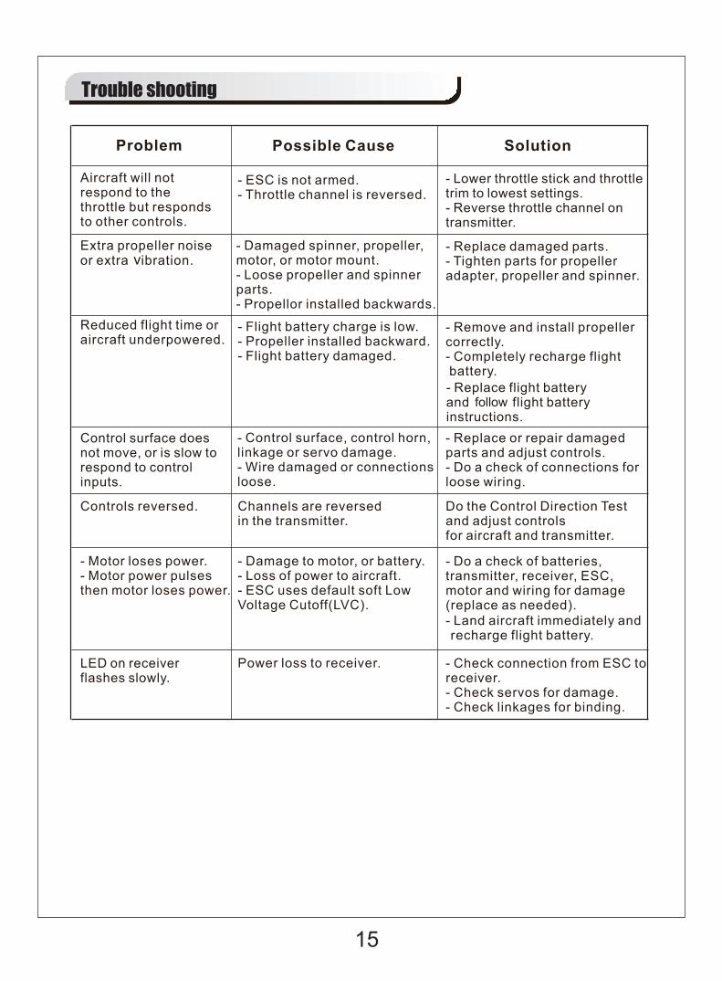
Trouble shooting
15

FMSPW101PUR FuselageFMSPW102PUR Main Wing SetFMSPW103PUR Vertical StabilizerFMSPW104PUR Horizontal StabilizerFMSPW105PUR CockpitFMSPW106 Front Landing Gear DoorFMSPW107 Wheel SetFMSPW108 PipeFMSPW109 Linkage RodFMSPW110 Screw SetFMSPW111PUR Control HornsFMSPW112 Front Landing Gear SetFMSPW113 Main Landing Gear SetFMSPW114 Front Landing Gear SystemFMSPW115PUR Main Landing Gear SystemFMSPW116PUR Decal SheetFMSRE030 Electronic RetractFMSRE011 Electronic RetractFMSCON003 Multi Connector SystemFMS80MM12B Ducted fan (12-blades)PRKV2000 3270-KV2000 motorPRESC014 100A ESCFMSSER9MGDP 9g digital metal gear servo positiveFMSSER9MGDR 9g digital metal gear servo reverse
FMSPW101RED FuselageFMSPW102RED Main Wing SetFMSPW103RED Vertical StabilizerFMSPW104RED Horizontal StabilizerFMSPW105RED CockpitFMSPW106 Front Landing Gear DoorFMSPW107 Wheel SetFMSPW108 PipeFMSPW109 Linkage RodFMSPW110 Screw SetFMSPW111RED Control HornsFMSPW112 Front Landing Gear SetFMSPW113 Main Landing Gear SetFMSPW114 Front Landing Gear SystemFMSPW115RED Main Landing Gear SystemFMSPW116RED Decal SheetFMSRE030 Electronic RetractFMSRE011 Electronic RetractFMSCON003 Multi Connector SystemFMS80MM12B Ducted fan (12-blades)PRKV2000 3270-KV2000 motorPRESC014 100A ESCFMSSER9MGDP 9g digital metal gear servo positiveFMSSER9MGDR 9g digital metal gear servo reverse
Visit our website to see photos of this product: www.fmsmodel.com
Spare parts list content
16
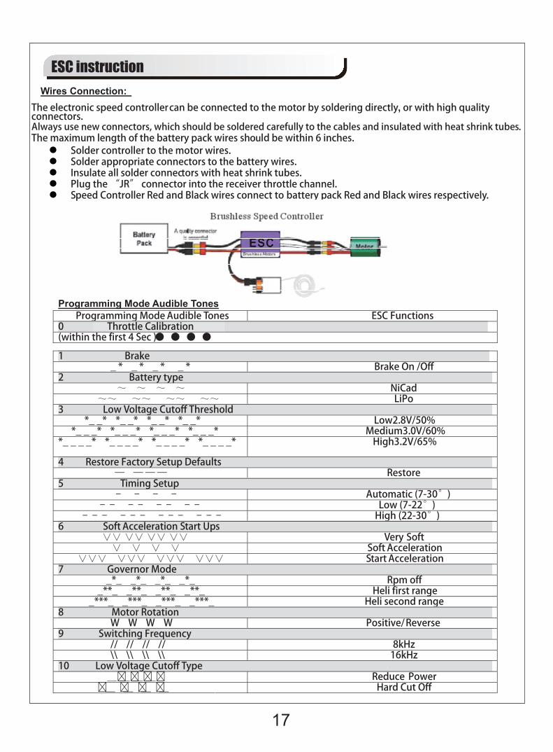
ESC instruction
17