Embed Size (px)
Citation preview
JOHN DEEREAG & TURF DIVISION
M163884
B2
Sprayer25, 45 and 90 Gallon
OMM163884 B2
OPERATOR’S MANUAL
Original InstructionAll information, illustrations and
specifications in this manual are based on the latest information at the time of
publication. The right is reserved to make changes at any time without notice.
COPYRIGHT© 2012Deere & Co.
John Deere Ag & Turf DivisionAll rights reservedPrevious Editions
COPYRIGHT© 2011
North American VersionLitho in U.S.A.
Introduc
Introduction
Table of ContentsIntroduction................................................................................................ 1
Product Identification................................................................................. 1
Safety Labels............................................................................................. 2
Safety ........................................................................................................ 3
Assembly................................................................................................... 4
Installing .................................................................................................. 13
Preparing Vehicle .................................................................................... 13
Removing and Storing............................................................................. 13
Operating................................................................................................. 14
Service .................................................................................................... 19
Troubleshooting ....................................................................................... 20
Specifications .......................................................................................... 20
Getting Quality Service ........................................................................... 21
IntroductionUsing Your Operator’s ManualRead this entire operator’s manual, especially the safety information, before operating.
This manual is an important part of your machine. Keep all manuals in a convenient location so they can be accessed easily.
Use the safety and operating information in the attachment operator’s manual, along with the machine operator’s manual, to operate and service the attachment safely and correctly.
If your attachment manual has a section called Preparing the Machine, it means that you will have to do something to your tractor or vehicle before you can install the attachment. The Assembly and Installation sections of this manual provide information to assemble and install the attachment to your tractor or vehicle. Use the Service section to make any needed adjustments and routine service to your attachment.
If you have any questions or concerns with the assembly, installation, or operation of this attachment, see your local John Deere dealer or call the John Deere Customer Contact Center at 1-800-537-8233 for assistance.
Warranty information on this John Deere attachment can be found in the warranty that came with your John Deere tractor or vehicle.
Product IdentificationProduct CompatibilityThis Sprayer is designed for use with John Deere Gator™ Utility Vehicles.
Contact your John Deere dealer for specific utility vehicle compatibility information.
tion - 1
Safety Labels
Safety LabelsUnderstanding The Machine Safety LabelsThe machine safety labels shown in this section are placed in important areas on your machine to draw attention to potential safety hazards.
On your machine safety labels, the words DANGER, WARNING, and CAUTION are used with this safety-alert symbol. DANGER identifies the most serious hazards.
The operator’s manual also explains any potential safety hazards whenever necessary in special safety messages that are identified with the word, CAUTION, and the safety-alert symbol.
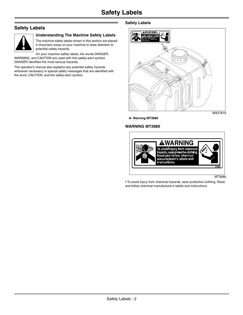
Safety Labels
MX27819
A- Warning MT3980
WARNING MT3980
MT3980
• To avoid injury from chemical hazards, wear protective clothing. Read and follow chemical manufacturer’s labels and instructions.
A
Safety Labels - 2
Safety
SafetyRead Safety in Machine Operator’s ManualRead the general safety operating precautions in your machine operator’s manual for additional safety information.
Operate Safely
• Read the machine and attachment operator’s manual carefully. Be thoroughly familiar with the controls and the proper use of the equipment. Know how to stop the machine and disengage the controls quickly.
• Do not let children or an untrained person operate machine.
• Make any necessary adjustments before you operate. Never attempt to make any adjustments while the engine is running, unless if recommended in adjustment procedure.
• Take all possible precautions when leaving the machine unattended. Shut off the engine before making any repairs, adjustments, or inspections. Lower the attachment, lock the parking brake, stop the engine, and remove the key.
• Look behind machine before you back up. Back up carefully.
• Do not let anyone, especially children, ride on machine or attachment. Riders are subject to injury such as being struck by foreign objects and being thrown off. Riders may also obstruct the operator’s view, resulting in the machine being operated in an unsafe manner.
• Use only attachments and accessories approved by the manufacturer of this product.
• If the machine vibrates abnormally, stop the engine and check immediately for the cause. Vibration is generally a warning of trouble.
• Always refer to the Storage section of the operator’s manual for important details if storing this product for a long period of time.
• Keep people and pets out of the work area. Stop machine if anyone enters the area.
• If you hit an object, stop the machine and inspect it. Make repairs before you operate. Keep machine properly maintained and in good working order. Keep all shields and guards in place.
• Always inspect the sprayer completely before and after each use. Before pressurizing the system, check to be sure all fittings and hoses are tightly installed. Be sure guards and shields are in good condition and fastened in place. Make any necessary adjustments before you operate.
• Never use the sprayer during windy conditions.
• Always release pressure in the system before filling, cleaning or servicing the sprayer.
• Do not put nozzle tip or other sprayer parts to your lips to blow out dirt. Use compressed air.
• If the sprayer is mounted to the bed of a utility vehicle, never raise the bed with the sprayer installed. Empty the sprayer and remove it from the bed if you need to raise the bed for any reason.
Parking Safely
1. Stop vehicle on a level surface, not on a slope.
2. Lock park brake.
3. Stop engine.
4. Remove key.
5. Before you leave the operator’s seat, wait for engine and all moving parts to stop.
6. Disconnect the negative battery cable or remove the spark plug wires (for gasoline engines) before servicing the machine.
Mix and Handle Chemicals Safely
• It is best to wear full cover clothing and always wear protective goggles and rubber gloves to protect yourself while handling chemicals.
• Follow instructions on chemical container labels.
• Open all chemical containers carefully, using proper tools.
• Open, pour, weigh and mix chemicals in a well-ventilated area.
• Reserve all equipment used for the application of chemicals exclusively for that purpose.
• Prohibit all smoking, drinking and eating food in chemical-handling area.
• It is a good practice to take a soapy shower immediately after the using the sprayer to apply chemicals.
• Wash all clothing worn when using chemicals separately in the laundry after spraying is completed.
Read Chemical Container Label
• Chemicals can be dangerous. Improper selection or use can injure persons, animals, plants, soils or other property. Select the right chemical for the job and handle and apply with care.
• Read the instructions, precautions, and warnings on the container label before opening. Use the product strictly according to label directions for specific applications, in the amounts specified, at the times specified and only when needed.
• Keep the container closed tightly except when preparing the mix.
• Do not remove labels from chemical containers. Store all chemicals in their original containers.
• Do not mix chemicals unless stated on the container label.
• Store chemicals when not in use according to the container label.
Handle Chemical Products Safely
• Direct exposure to hazardous chemicals can cause serious injury. Potentially hazardous chemicals used with John Deere equipment include pesticides, herbicides and fungicides.
• A Material Safety Data Sheet (MSDS) provides specific details on chemical products: physical and health hazards, safety procedures, and emergency response techniques.
• The MSDS should be obtained from the chemical dealer at the time of the chemical purchase.
• Check the MSDS before beginning any job using a hazardous chemical. Know exactly what the risks are and how to do the job safely. Always wear recommended personal protection equipment.
Practice Safe Maintenance
• Only qualified, trained adults should service this machine.
• Understand service procedure before doing work. Keep area clean and dry.
• Do not operate the engine in a confined space where dangerous carbon monoxide fumes can collect.
• Never lubricate, service or adjust the machine or attachment while it is moving. Keep safety devices in place and in working condition. Keep hardware tight.
• Keep hands, feet, clothing, jewelry, and long hair away from any moving parts, to prevent them from getting caught.
Safety - 3
Assembly
• Lower any attachment completely to the ground or to an existing attachment mechanical stop before servicing the attachment. Disengage all power and stop the engine. Lock park brake and remove the key. Let machine cool.• Disconnect battery or remove spark plug wire (for gasoline engines) before making any repairs.
• Before servicing machine or attachment, carefully release pressure from any components with stored energy, such as hydraulic components and springs.
• Release hydraulic pressure by lowering attachment or cutting units to the ground or to a mechanical stop and move hydraulic control levers.
• Securely support any machine or attachment elements that must be raised for service work. Use jack stands or lock service latches to support components when needed.
• Never run engine unless park brake is locked.
• Keep all parts in good condition and properly installed. Fix damage immediately. Replace worn or broken parts. Replace all worn or damaged safety and instruction decals.
• Check all hardware at frequent intervals to be sure the equipment is in safe working condition.
• Do not modify machine or safety devices. Unauthorized modifications to the machine or attachment may impair its function and safety.
Wear Appropriate Clothing
• Wear close fitting clothing and safety equipment appropriate for the job.
• Certain operating conditions may dictate that the operator and any passenger wear
appropriate safety equipment while operating the vehicle. Be prepared for any existing and potential conditions before operating machine.
• Local safety or insurance regulations may require additional safety equipment such as eye protection or a hard hat.
• Always wear substantial footwear and long trousers. Do not operate the equipment when barefoot or wearing open sandals.
• Wear proper clothing and safety equipment while handling chemicals or using the sprayer. Refer to the MSDS for the chemicals being used to be sure the proper personal protection equipment is being used.
Avoid High Pressure Fluids
• Hydraulic hoses and lines can fail due to physical damage, kinks, age, and exposure. Check hoses and lines regularly. Replace damaged hoses and lines.
• Hydraulic fluid connections can loosen due to physical damage and vibration. Check connections regularly. Tighten loose connections.
• Escaping fluid under pressure can penetrate the skin causing serious injury. Avoid the hazard by relieving pressure before disconnecting hydraulic or other lines. Tighten all connections before applying pressure.
• Search for leaks with a piece of cardboard. Protect hands and body from high pressure fluids.
• If an accident occurs, see a doctor immediately. Any fluid injected into the skin must be surgically removed within a few hours or gangrene may result. Doctors unfamiliar with this type of injury should reference a knowledgeable medical source. Such information is available from Deere & Company Medical Department in Moline, Illinois, U.S.A. Information may be obtained in the United States and Canada only by calling 1-800-822-8262.
Dispose of Chemicals Properly
• Proper disposal of excess spray material is very important. If you have excess tank solution, it is best to dilute it with water and apply it to the area you previously treated.
• Never dump solution into a drain or near a lake or stream.
• Chemicals containers should be triple-rinsed, with the rinse water added to the sprayer tank. Do not burn empty chemical containers. Dispose of containers at recycling centers.
Handling Waste Product and Chemicals Waste products, such as, used oil, fuel, coolant, brake fluid, and batteries, can harm the environment and people:
• Do not use beverage containers for waste fluids - someone may drink from them.
• See your local Recycling Center or authorized dealer to learn how to recycle or get rid of waste products.
• A Material Safety Data Sheet (MSDS) provides specific details on chemical products: physical and health hazards, safety procedures, and emergency response techniques. The seller of the chemical products used with your machine is responsible for providing the MSDS for that product.
Assembly25, 45 Gallon Sprayer Parts List
Hardware
Qty. Description
2 3/8 x 3-1/2 Carriage Bolt
4 3/8 x 1-1/2 Carriage Bolt
4 5/16 x 1 Flange Bolt
12 5/16 x 3/4 Flange Bolt
2 5/16 x 5/8 Flange Bolt
14 5/16 x 3/4 Carriage Bolt
4 3/8 Washer
6 3/8 Lockwasher
30 5/16 Flange Nut
6 Plastic Locking Knob
10 Rubber Foot, Small
2 Rubber Foot, Large
1 Wand Clip, Small (Standard)
2 Wand Clip, Large (Standard)
2 U-Bolt (HP model only)
1 Wire Clip
1 Hose Clamp (HP model only)
2 10-24 x 3/8 Truss Head Screw
Assembly - 4
Assembly
Wire Harness
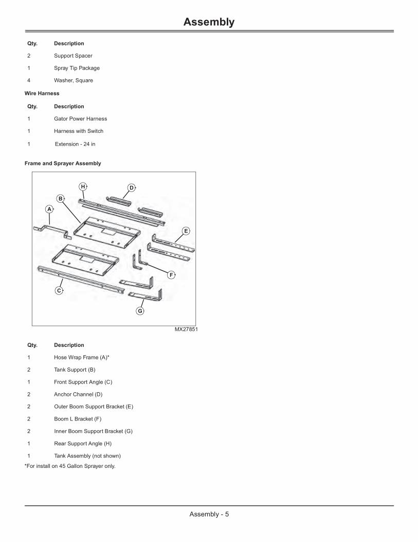
Frame and Sprayer Assembly
MX27851
*For install on 45 Gallon Sprayer only.
2 Support Spacer
1 Spray Tip Package
4 Washer, Square
Qty. Description
1 Gator Power Harness
1
1 Extension - 24 in
Harness with Switch
Qty. Description
1 Hose Wrap Frame (A)*
2 Tank Support (B)
1 Front Support Angle (C)
2 Anchor Channel (D)
Qty. Description
A
B
C
D
E
G
F
H
2 Outer Boom Support Bracket (E)
2 Boom L Bracket (F)
2 Inner Boom Support Bracket (G)
1 Rear Support Angle (H)
1 Tank Assembly (not shown)
Assembly - 5
Assembly
Assemble 25, 45 Gallon Sprayer
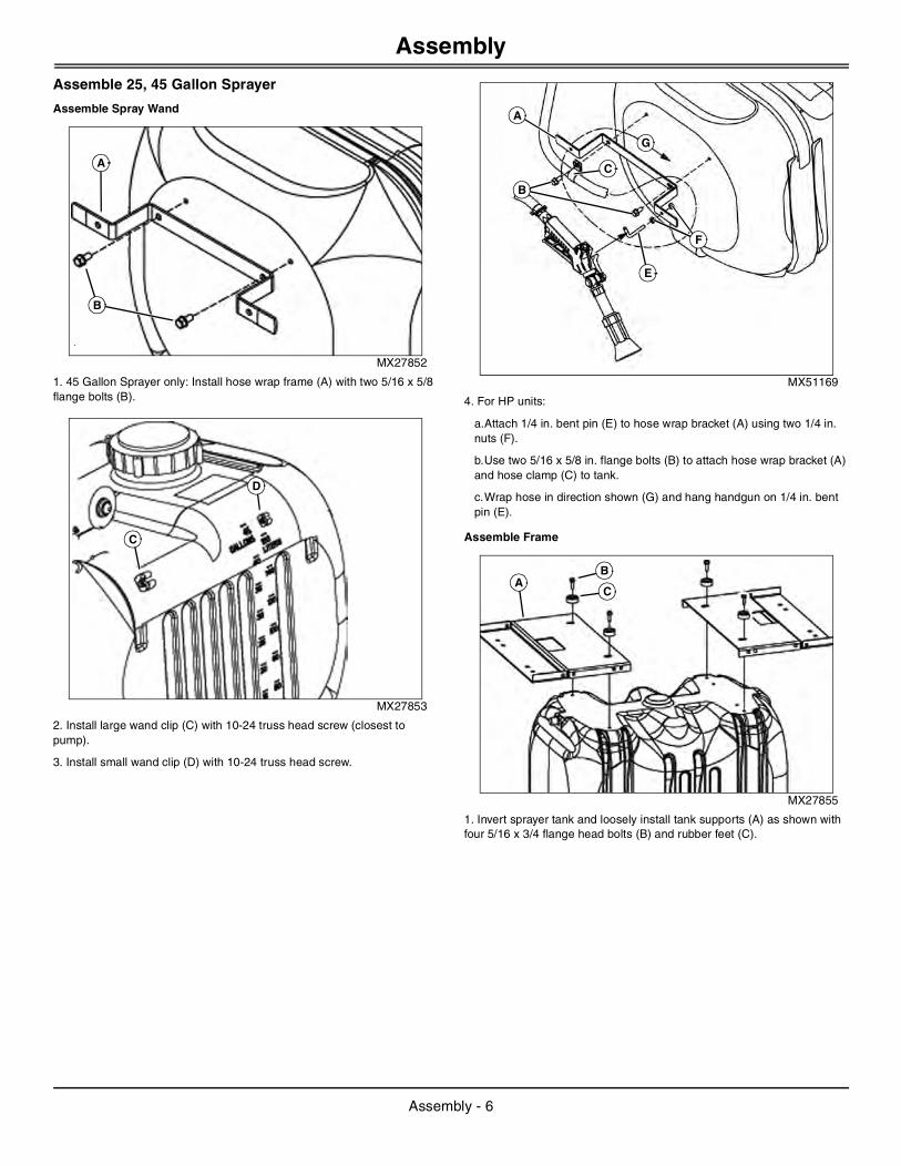
Assemble Spray Wand
MX27852
1. 45 Gallon Sprayer only: Install hose wrap frame (A) with two 5/16 x 5/8 flange bolts (B).
MX27853
2. Install large wand clip (C) with 10-24 truss head screw (closest to pump).
3. Install small wand clip (D) with 10-24 truss head screw.
MX51169
4. For HP units:
a.Attach 1/4 in. bent pin (E) to hose wrap bracket (A) using two 1/4 in. nuts (F).
b.Use two 5/16 x 5/8 in. flange bolts (B) to attach hose wrap bracket (A) and hose clamp (C) to tank.
c.Wrap hose in direction shown (G) and hang handgun on 1/4 in. bent pin (E).
Assemble Frame
MX27855
1. Invert sprayer tank and loosely install tank supports (A) as shown with four 5/16 x 3/4 flange head bolts (B) and rubber feet (C).
A
B
C
D
E
A
F
B
C
G
AB
C
Assembly - 6
Assembly
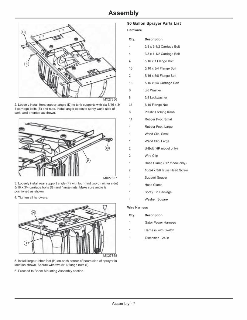
MX278562. Loosely install front support angle (D) to tank supports with six 5/16 x 3/4 carriage bolts (E) and nuts. Install angle opposite spray wand side of tank, and oriented as shown.
MX278573. Loosely install rear support angle (F) with four (first two on either side) 5/16 x 3/4 carriage bolts (G) and flange nuts. Make sure angle is positioned as shown.
4. Tighten all hardware.
MX278585. Install large rubber feet (H) on each corner of boom side of sprayer in location shown. Secure with two 5/16 flange nuts (I).
6. Proceed to Boom Mounting Assembly section.
90 Gallon Sprayer Parts ListHardware
Wire Harness
D
E
F
G
H
I
Qty. Description
4 3/8 x 3-1/2 Carriage Bolt
4 3/8 x 1-1/2 Carriage Bolt
4 5/16 x 1 Flange Bolt
16 5/16 x 3/4 Flange Bolt
2 5/16 x 5/8 Flange Bolt
18 5/16 x 3/4 Carriage Bolt
6 3/8 Washer
8 3/8 Lockwasher
36 5/16 Flange Nut
8 Plastic Locking Knob
14 Rubber Foot, Small
4 Rubber Foot, Large
1 Wand Clip, Small
1 Wand Clip, Large
2 U-Bolt (HP model only)
2 Wire Clip
1 Hose Clamp (HP model only)
2 10-24 x 3/8 Truss Head Screw
4 Support Spacer
1 Hose Clamp
1 Spray Tip Package
4 Washer, Square
Qty. Description
1 Gator Power Harness
1 Harness with Switch
1 Extension - 24 in
Assembly - 7
Assembly
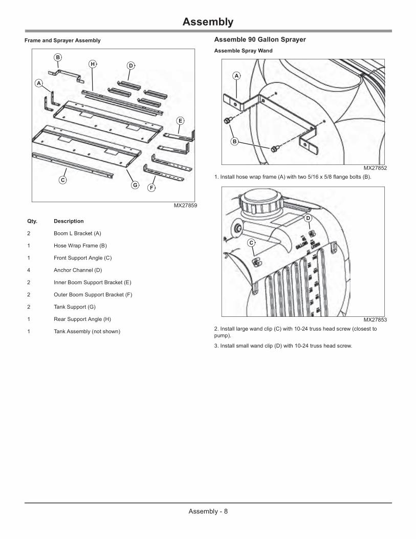
Frame and Sprayer AssemblyMX27859
Assemble 90 Gallon SprayerAssemble Spray Wand
MX278521. Install hose wrap frame (A) with two 5/16 x 5/8 flange bolts (B).
MX27853
2. Install large wand clip (C) with 10-24 truss head screw (closest to pump).
3. Install small wand clip (D) with 10-24 truss head screw.
Qty. Description
2 Boom L Bracket (A)
1 Hose Wrap Frame (B)
1 Front Support Angle (C)
4 Anchor Channel (D)
2 Inner Boom Support Bracket (E)
2 Outer Boom Support Bracket (F)
2 Tank Support (G)
1 Rear Support Angle (H)
1 Tank Assembly (not shown)
B
A
C
D
E
FG
H
A
B
C
D
Assembly - 8
Assembly
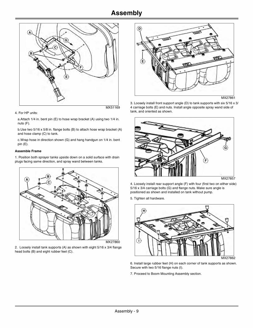
MX51169
4. For HP units:
a.Attach 1/4 in. bent pin (E) to hose wrap bracket (A) using two 1/4 in. nuts (F).
b.Use two 5/16 x 5/8 in. flange bolts (B) to attach hose wrap bracket (A) and hose clamp (C) to tank.
c.Wrap hose in direction shown (G) and hang handgun on 1/4 in. bent pin (E).
Assemble Frame
1. Position both sprayer tanks upside down on a solid surface with drain plugs facing same direction, and spray wand between tanks.
MX27860
2. Loosely install tank supports (A) as shown with eight 5/16 x 3/4 flange head bolts (B) and eight rubber feet (C).
MX27861
3. Loosely install front support angle (D) to tank supports with six 5/16 x 3/4 carriage bolts (E) and nuts. Install angle opposite spray wand side of tank, and oriented as shown.
MX27857
4. Loosely install rear support angle (F) with four (first two on either side) 5/16 x 3/4 carriage bolts (G) and flange nuts. Make sure angle is positioned as shown and installed on tank without pump.
5. Tighten all hardware.
MX27862
6. Install large rubber feet (H) on each corner of tank supports as shown. Secure with two 5/16 flange nuts (I).
7. Proceed to Boom Mounting Assembly section.
E
A
F
B
C
G
AB
C
D
E
F
G
H
I
Assembly - 9
Assembly
Boom Mounting Assembly
Boom Support Bracket Assembly
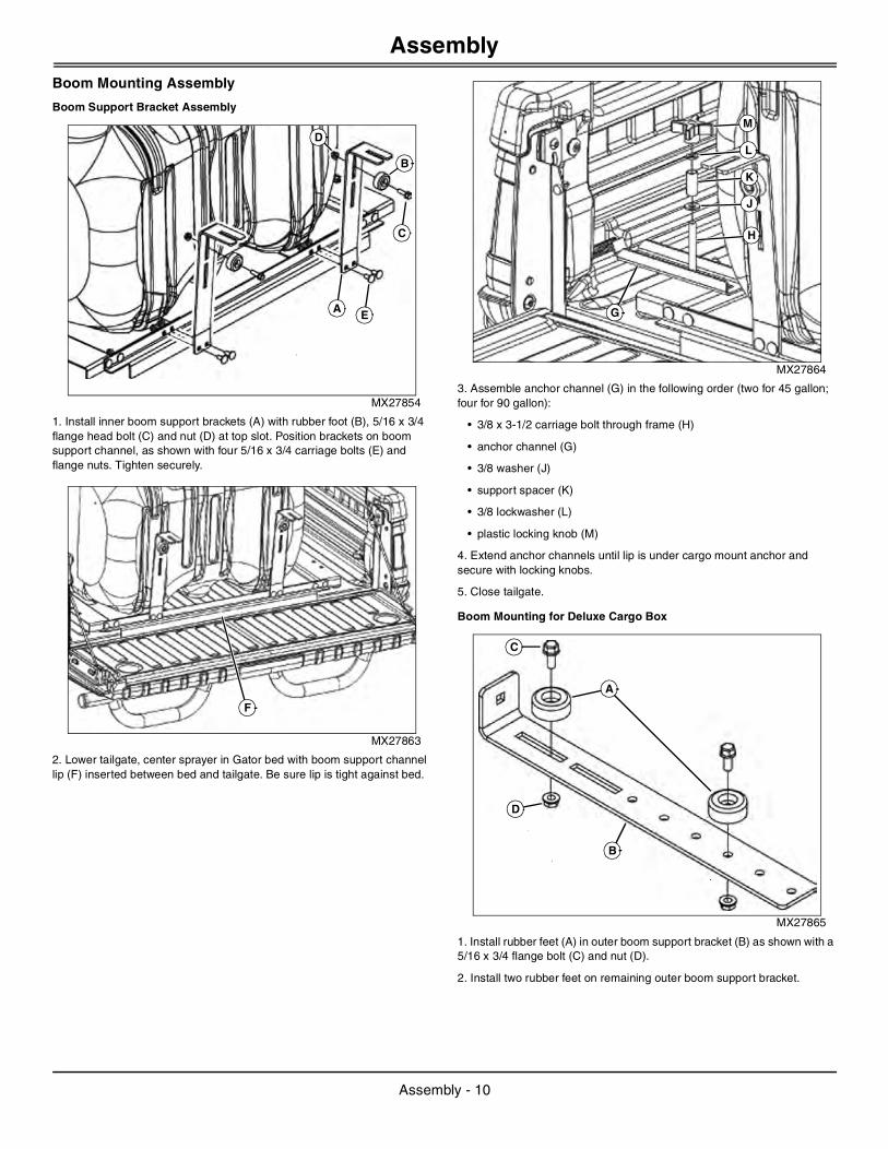
MX27854
1. Install inner boom support brackets (A) with rubber foot (B), 5/16 x 3/4 flange head bolt (C) and nut (D) at top slot. Position brackets on boom support channel, as shown with four 5/16 x 3/4 carriage bolts (E) and flange nuts. Tighten securely.
MX27863
2. Lower tailgate, center sprayer in Gator bed with boom support channel lip (F) inserted between bed and tailgate. Be sure lip is tight against bed.
MX27864
3. Assemble anchor channel (G) in the following order (two for 45 gallon; four for 90 gallon):
• 3/8 x 3-1/2 carriage bolt through frame (H)
• anchor channel (G)
• 3/8 washer (J)
• support spacer (K)
• 3/8 lockwasher (L)
• plastic locking knob (M)
4. Extend anchor channels until lip is under cargo mount anchor and secure with locking knobs.
5. Close tailgate.
Boom Mounting for Deluxe Cargo Box
MX27865
1. Install rubber feet (A) in outer boom support bracket (B) as shown with a 5/16 x 3/4 flange bolt (C) and nut (D).
2. Install two rubber feet on remaining outer boom support bracket.
A E
D
B
C
F
G
H
J
K
L
M
D
B
A
C
Assembly - 10
Assembly
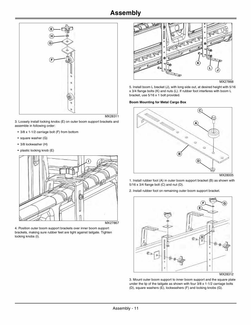
MX28311
3. Loosely install locking knobs (E) on outer boom support brackets and assemble in following order:
• 3/8 x 1-1/2 carriage bolt (F) from bottom
• square washer (G)
• 3/8 lockwasher (H)
• plastic locking knob (E)
MX27867
4. Position outer boom support brackets over inner boom support brackets, making sure rubber feet are tight against tailgate. Tighten locking knobs (I).
MX27868
5. Install boom L bracket (J), with long side out, at desired height with 5/16 x 3/4 flange bolts (K) and nuts (L). If rubber foot interferes with boom L bracket, use 5/16 x 1 bolt provided.
Boom Mounting for Metal Cargo Box
MX28005
1. Install rubber foot (A) in outer boom support bracket (B) as shown with 5/16 x 3/4 flange bolt (C) and nut (D).
2. Install rubber foot on remaining outer boom support bracket.
MX28312
3. Mount outer boom support to inner boom support and the square plate under the lip of the tailgate as shown with four 3/8 x 1-1/2 carriage bolts (D), square washers (E), lockwashers (F) and locking knobs (G).
E
H
G
F
I
L J
K
A
B
C
D
D
E
F G
Assembly - 11
Assembly
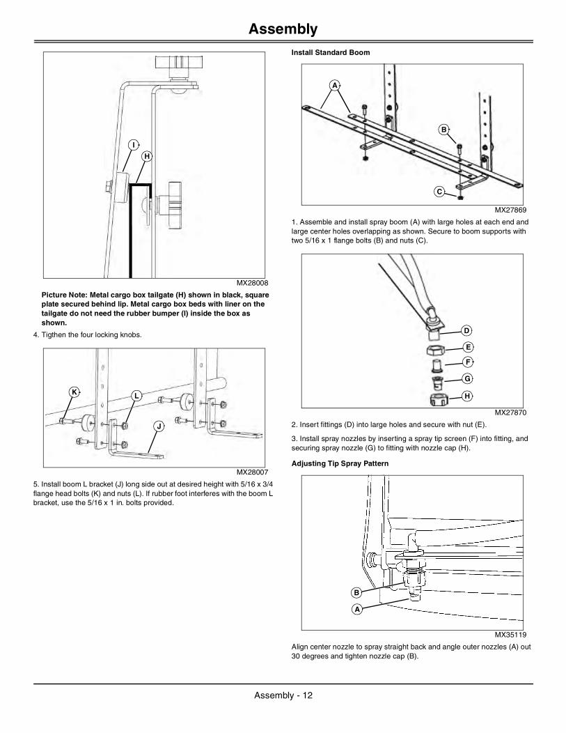
MX28008
Picture Note: Metal cargo box tailgate (H) shown in black, square plate secured behind lip. Metal cargo box beds with liner on the tailgate do not need the rubber bumper (I) inside the box as shown.
4. Tigthen the four locking knobs.
MX28007
5. Install boom L bracket (J) long side out at desired height with 5/16 x 3/4 flange head bolts (K) and nuts (L). If rubber foot interferes with the boom L bracket, use the 5/16 x 1 in. bolts provided.
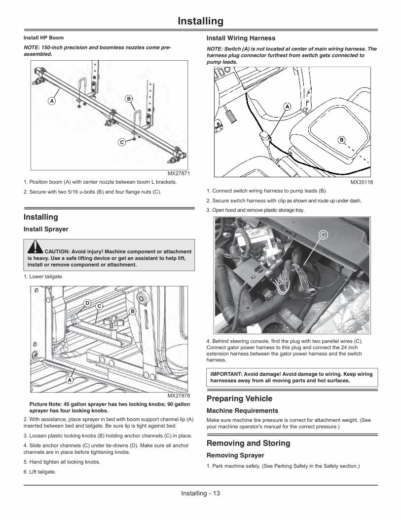
Install Standard Boom
MX27869
1. Assemble and install spray boom (A) with large holes at each end and large center holes overlapping as shown. Secure to boom supports with two 5/16 x 1 flange bolts (B) and nuts (C).
MX27870
2. Insert fittings (D) into large holes and secure with nut (E).
3. Install spray nozzles by inserting a spray tip screen (F) into fitting, and securing spray nozzle (G) to fitting with nozzle cap (H).
Adjusting Tip Spray Pattern
MX35119
Align center nozzle to spray straight back and angle outer nozzles (A) out 30 degrees and tighten nozzle cap (B).
H
I
J
K L
A
B
C
D
E
F
G
H
A
B
Assembly - 12
Installing
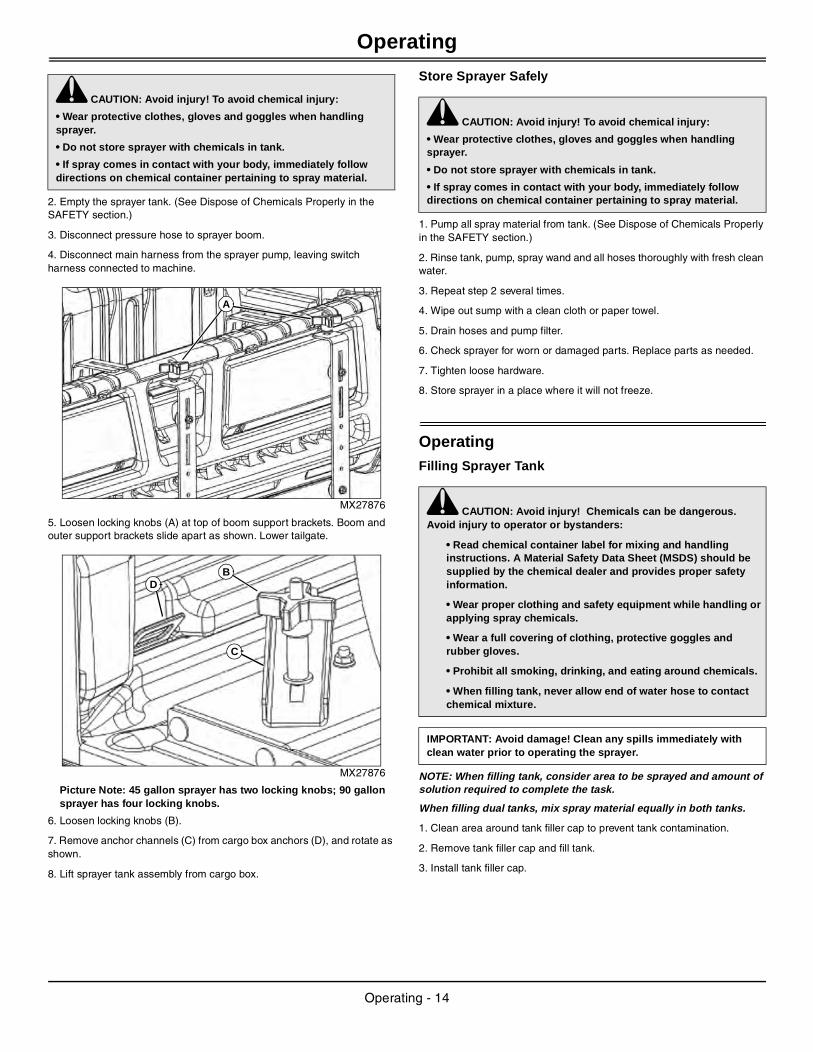
Install HP BoomNOTE: 150-inch precision and boomless nozzles come pre-assembled.
MX278711. Position boom (A) with center nozzle between boom L brackets.
2. Secure with two 5/16 u-bolts (B) and four flange nuts (C).
InstallingInstall Sprayer
1. Lower tailgate.
MX27878Picture Note: 45 gallon sprayer has two locking knobs; 90 gallon sprayer has four locking knobs.
2. With assistance, place sprayer in bed with boom support channel lip (A) inserted between bed and tailgate. Be sure lip is tight against bed.
3. Loosen plastic locking knobs (B) holding anchor channels (C) in place.
4. Slide anchor channels (C) under tie-downs (D). Make sure all anchor channels are in place before tightening knobs.
5. Hand tighten all locking knobs.
6. Lift tailgate.
Install Wiring Harness
NOTE: Switch (A) is not located at center of main wiring harness. The harness plug connector furthest from switch gets connected to pump leads.
MX351181. Connect switch wiring harness to pump leads (B).
2. Secure switch harness with clip as shown and route up under dash.
4. Behind steering console, find the plug with two parellel wires (C).Connect gator power harness to this plug and connect the 24 inch extension harness between the gator power harness and the switch harness.
Preparing VehicleMachine RequirementsMake sure machine tire pressure is correct for attachment weight. (See your machine operator’s manual for the correct pressure.)
Removing and StoringRemoving Sprayer
1. Park machine safely. (See Parking Safely in the Safety section.)
c CAUTION: Avoid injury! Machine component or attachment is heavy. Use a safe lifting device or get an assistant to help lift, install or remove component or attachment.
B
C
A
A
BCD
IMPORTANT: Avoid damage! Avoid damage to wiring. Keep wiring harnesses away from all moving parts and hot surfaces.
3. Open hood and remove plastic storage tray.
C
Installing - 13
Operating
2. Empty the sprayer tank. (See Dispose of Chemicals Properly in the SAFETY section.)
3. Disconnect pressure hose to sprayer boom.
4. Disconnect main harness from the sprayer pump, leaving switch harness connected to machine.
MX27876
5. Loosen locking knobs (A) at top of boom support brackets. Boom and outer support brackets slide apart as shown. Lower tailgate.
MX27876
Picture Note: 45 gallon sprayer has two locking knobs; 90 gallon sprayer has four locking knobs.
6. Loosen locking knobs (B).
7. Remove anchor channels (C) from cargo box anchors (D), and rotate as shown.
8. Lift sprayer tank assembly from cargo box.
Store Sprayer Safely
1. Pump all spray material from tank. (See Dispose of Chemicals Properly in the SAFETY section.)
2. Rinse tank, pump, spray wand and all hoses thoroughly with fresh clean water.
3. Repeat step 2 several times.
4. Wipe out sump with a clean cloth or paper towel.
5. Drain hoses and pump filter.
6. Check sprayer for worn or damaged parts. Replace parts as needed.
7. Tighten loose hardware.
8. Store sprayer in a place where it will not freeze.
OperatingFilling Sprayer Tank
NOTE: When filling tank, consider area to be sprayed and amount of solution required to complete the task.
When filling dual tanks, mix spray material equally in both tanks.
1. Clean area around tank filler cap to prevent tank contamination.
2. Remove tank filler cap and fill tank.
3. Install tank filler cap.
c CAUTION: Avoid injury! To avoid chemical injury:
• Wear protective clothes, gloves and goggles when handling sprayer.
• Do not store sprayer with chemicals in tank.
• If spray comes in contact with your body, immediately follow directions on chemical container pertaining to spray material.
A
BD
C
c CAUTION: Avoid injury! To avoid chemical injury:
• Wear protective clothes, gloves and goggles when handling sprayer.
• Do not store sprayer with chemicals in tank.
• If spray comes in contact with your body, immediately follow directions on chemical container pertaining to spray material.
c CAUTION: Avoid injury! Chemicals can be dangerous. Avoid injury to operator or bystanders:
• Read chemical container label for mixing and handling instructions. A Material Safety Data Sheet (MSDS) should be supplied by the chemical dealer and provides proper safety information.
• Wear proper clothing and safety equipment while handling or applying spray chemicals.
• Wear a full covering of clothing, protective goggles and rubber gloves.
• Prohibit all smoking, drinking, and eating around chemicals.
• When filling tank, never allow end of water hose to contact chemical mixture.
IMPORTANT: Avoid damage! Clean any spills immediately with clean water prior to operating the sprayer.
Operating - 14
Operating
Draining and Cleaning Sprayer Tank
1. Remove tank drain cap, and empty sprayer tank:
• Empty remaining solution into an appropriated container for proper disposal.
2. Spray all inside surfaces of tank with low pressure garden hose to remove any remaining solution. Rinse several times to make sure sprayer tank is clean and free of chemicals.
3. Replace drain cap and run fresh, clean water through pump, sprayer wand and all hoses thoroughly.
4. Once the tank is empty, wipe out inside of sprayer tank with a clean cloth or paper towel.
Starting and Stopping Sprayer
NOTE: The sprayer pump to accessory outlet hookup is a direct electrical connection. Shutting off the transport vehicle does not prevent operation of the sprayer pump. To avoid accidental spraying, disconnect the pump connection before leaving the sprayer.
MX35120
1. Push switch (A) to ON position to start the sprayer.
2. Push switch (A) to OFF position to stop the sprayer.
Sprayer ControlsPump and valve assemblies are different for each model. Locate model below that corresponds to your unit for correct control definition.
LP20852 - 45 Gallon Standard
MX27873
Valve (A) is used to control spray to the spray wand or boom:
• In the open position (valve in line with hose) spray will flow to the boom.
• In the closed position (handle perpendicular to hose), spray will flow to spray wand only.
LP22908 - HP 45 Gallon
MX27872
Turn knob (A) clockwise to control pressure and recirculation.
Turn knob (A) counter clockwise to recirculate more material to tank and adjust pressure to boom or wand.
Use valve (B) to route spray to spray gun or boom. The direction the handle is pointing, is the direction of flow.
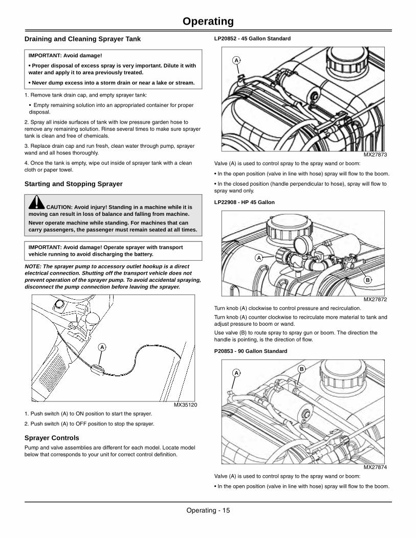
P20853 - 90 Gallon Standard
MX27874
Valve (A) is used to control spray to the spray wand or boom:
• In the open position (valve in line with hose) spray will flow to the boom.
IMPORTANT: Avoid damage!
• Proper disposal of excess spray is very important. Dilute it with water and apply it to area previously treated.
• Never dump excess into a storm drain or near a lake or stream.
c CAUTION: Avoid injury! Standing in a machine while it is moving can result in loss of balance and falling from machine.
Never operate machine while standing. For machines that can carry passengers, the passenger must remain seated at all times.
IMPORTANT: Avoid damage! Operate sprayer with transport vehicle running to avoid discharging the battery.
A
A
A
B
AB
Operating - 15
Operating
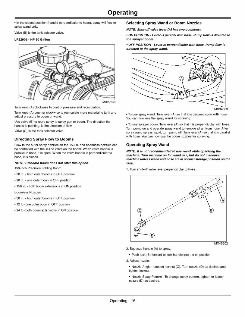
• In the closed position (handle perpendicular to hose), spray will flow to spray wand only.Valve (B) is the tank selector valve.
LP22909 - HP 90 Gallon
MX27875
Turn knob (A) clockwise to control pressure and recirculation.
Turn knob (A) counter clockwise to recirculate more material to tank and adjust pressure to boom or wand.
Use valve (B) to route spray to spray gun or boom. The direction the handle is pointing, is the direction of flow.
Valve (C) is the tank selector valve.
Directing Spray Flow to BoomsFlow to the outer spray nozzles on the 150 in. and boomless nozzles can be controlled with the in-line valve on the boom. When valve handle is parallel to hose, it is open. When the valve handle is perpendicular to hose, it is closed.
NOTE: Standard boom does not offer this option:
150-inch Precision Folding Boom:
• 30 in. - both outer booms in OFF position
• 90 in. - one outer boon in OFF position
• 150 in. - both boom extensions in ON position
Boomless Nozzles:
• 30 in. - both outer booms in OFF position
• 12 ft - one outer boon in OFF position
• 24 ft - both boom extensions in ON position
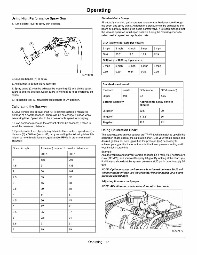
Selecting Spray Wand or Boom Nozzles
NOTE: Shut-off valve lever (A) has two positions:
• ON POSITION - Lever is parallel with hose. Pump flow is directed to the sprayer boom.
• OFF POSITION - Lever is perpendicular with hose. Pump flow is directed to the spray wand.
MX34863
• To use spray wand: Turn lever (A) so that it is perpendicular with hose. You can now use the spray wand for spraying.
• To use sprayer boom: Turn lever (A) so that it is perpendicular with hose. Turn pump on and operate spray wand to remove all air from hose. After spray wand sprays liquid, turn pump off. Turn lever (A) so that it is parallel with hose. You can now use the boom nozzles for spraying.
Operating Spray Wand
NOTE: It is not recommended to use wand while operating the machine. Turn machine on for wand use, but do not maneuver machine unless wand and hose are in normal storage position on the tank.
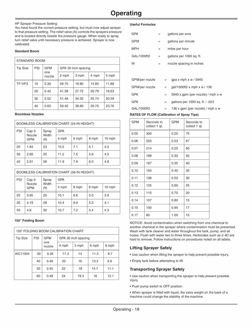
1. Turn shut-off valve lever perpendicular to hose.
MX45502
2. Squeeze handle (A) to spray.
• Push lock (B) forward to lock handle into the on position.
3. Adjust nozzle:
• Nozzle Angle - Loosen locknut (C). Turn nozzle (D) as desired and tighten locknut.
• Nozzle Spray Pattern - To change spray pattern, tighten or loosen nozzle (D) as desired.
A
B
C
A
B
A
C
D
Operating - 16
Operating
Using High Performance Spray Gun
1. Turn selector lever to spray gun position.
MX43065
2. Squeeze handle (A) to spray.
3. Adjust mist to stream using lever (B).
4. Spray guard (C) can be adjusted by loosening (D) and sliding spray guard to desired position. Spray guard is intended to keep overspray off hands.
5. Flip handle lock (E) forward to lock handle in ON position.
Calibrating the Sprayer
1. Drive vehicle and sprayer (half-full is optimal) across a measured distance at a constant speed. There can be no change in speed while measuring time. Speed should be a comfortable speed for spraying.
2. Have someone measure the amount of time (in seconds) it takes to travel the measured distance.
3. Speed can be found by entering data into the equation: speed (mph) = distance (ft) x 60/time (sec) x 88, or by consulting the following table. It is helpful to note throttle location, gear and/or RPMs in order to maintain accuracy.
Standard Gator Sprayer
All capacity standard gator sprayers operate at a fixed pressure through the boom and spray wand. Although the pressure can be adjusted to the boom by partially opening the boom control valve, it is recommended that the valve is operated in full open position. Using the following charts to select desired speed and application rate.
Using Calibration ChartThe spray nozzles on your sprayer are TF-VP3, which matches up with the calibration chart. Look at the calibration chart. Use your vehicle speed and desired gallons per acre (gpa), find the pressure (psi) necessary to achieve your gpa. It is important to note that lower pressure settings will result in less spray drift.
Example:Assume you have found your vehicle speed to be 4 mph, your nozzles are Grey (TF-VP3), and you want to spray 20 gpa. By looking at the chart, you find that you should set the sprayer pressure at 20 psi in order to apply 20 gpa.
NOTE: Optimum spray performance is achieved between 20-25 psi. When shutting off tips use the regulator valve to adjust your boom pressure accordingly.
Adjusting Pressure on Sprayer
NOTE: All calibration needs to be done with clean water.
MX27872
Speed in mph Time (sec) required to travel a distance of:
200 ft 300 ft
1 136 205
1.5 91 136
2 68 102
2.5 55 82
3 45 68
3.5 39 58
4 34 51
4.5 30 45
5 27 41
5.5 25 37
6 23 34
6.5 21 31
7 19 29
C
B A
D
E
GPA (gallons per acre per nozzle)
2 mph 3 mph 4 mph 5 mph 6 mph
38.6 25.7 19.3 15.4 12.9
Gallons per 1000 sq ft per nozzle
2 mph 3 mph 4 mph 5 mph 6 mph
0.89 0.59 0.44 0.35 0.30
Standard Hand Wand
Pressure Nozzle GPM (cone) GPM (stream)
80 psi #18 0.4 1.25
Sprayer Capacity Approximate Spray Time in Minutes
25 gallon 62.5 20
45 gallon 112.5 36
90 gallon 225 72
A
Operating - 17
Operating
HP Sprayer Pressure Setting:You have found the correct pressure setting, but must now adjust sprayer to that pressure setting. The relief valve (A) controls the sprayers pressure and is located directly beside the pressure gauge. When ready to spray, turn relief valve until necessary pressure is achieved. Sprayer is now calibrated.Standard Boom
Boomless Nozzles
Useful Formulas
RATES OF FLOW (Calibration of Spray Tips)
NOTICE: Avoid contamination when switching from one chemical to another chemical in the sprayer where contamination must be prevented. Wash with tank cleaner and water throughout the tank, pump, and all hoses. Flush with water two to three times. Herbicides such as 2-4D are hard to remove. Follow instructions on procedures noted on all labels.
Lifting Sprayer Safely
• Use caution when lifting the sprayer to help prevent possible injury.
• Empty tank before attempting to lift.
Transporting Sprayer Safely
• Use caution when transporting the sprayer to help prevent possible injury.
• Push pump switch to OFF position.
• When sprayer is filled with liquid, the extra weight on the back of a machine could change the stability of the machine.
STANDARD BOOM
Tip Size PSI GPM one nozzle
GPA 30 inch spacing
2 mph 3 mph 4 mph 5 mph
TF-VP3 10 0.30 29.70 19.80 14.85 11.88
20 0.42 41.58 27.72 20.79 16.63
30 0.52 51.48 34.32 25.74 20.59
40 0.60 59.40 39.60 29.70 23.76
BOOMLESS CALIBRATION CHART (24-IN HEIGHT)
PSI Cap 3 Nozzle GPM
Spray Width (ft)
GPA
4 mph 6 mph 8 mph 10 mph
20 1.84 23 10.5 7.1 5.1 4.2
30 2.60 25 11.2 7.5 5.6 4.5
40 2.91 28 11.9 7.9 6.0 4.8
BOOMLESS CALIBRATION CHART (36-IN HEIGHT)
PSI Cap 3 Nozzle GPM
Spray Width (ft)
GPA
4 mph 6 mph 8 mph 10 mph
20 3.65 25 10.1 6.6 5.0 3.9
30 4.19 28 10.4 6.9 5.2 4.1
40 4.8 30 10.7 7.2 5.4 4.3
GPA = gallons per acre
GPM = gallons per minute
MPH = miles per hour
GAL/1000ft2 = gallons per 1000 sq. ft.
W = nozzle spacing in inches
GPM/per nozzle = gpa x mph x w / 5940
GPM/per nozzle = gal/1000ft2 x mph x w / 136
GPA = 5940 x gpm (per nozzle) / mph x w
GPA = gallons per 1000 sq. ft. / .023
GAL/1000ft2 = 136 x gpm (per nozzle) / mph x w
GPM Seconds to collect 1 qt.
GPM Seconds to collect 1 qt.
0.05 300 0.20 75
0.06 250 0.23 67
0.07 214 0.25 60
0.08 188 0.30 50
0.09 167 0.35 40
0.10 150 0.40 35
0.11 136 0.50 30
0.12 125 0.60 25
0.13 115 0.70 20
0.14 107 0.80 15
0.15 100 0.90 17
0.17 80 1.00 15
Boom
150” FOLDING BOOM CALIBRATION CHART
Tip Size PSI GPM one nozzle
GPA 30 inch spacing
4 mph 5 mph 6 mph 8 mph
AIC11004 30 0.35 17.3 14 11.5 8.7
40 0.40 20 16 13.2 9.9
50 0.45 22 18 14.7 11.1
60 0.49 24 19.3 16 12.1
Operating - 18
Service
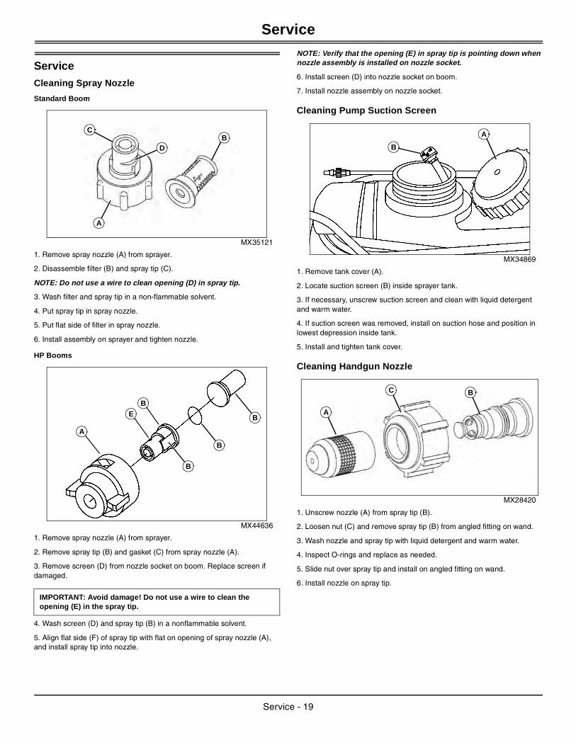
ServiceCleaning Spray Nozzle
Standard Boom
MX35121
1. Remove spray nozzle (A) from sprayer.
2. Disassemble filter (B) and spray tip (C).
NOTE: Do not use a wire to clean opening (D) in spray tip.
3. Wash filter and spray tip in a non-flammable solvent.
4. Put spray tip in spray nozzle.
5. Put flat side of filter in spray nozzle.
6. Install assembly on sprayer and tighten nozzle.
HP Booms
MX44636
1. Remove spray nozzle (A) from sprayer.
2. Remove spray tip (B) and gasket (C) from spray nozzle (A).
3. Remove screen (D) from nozzle socket on boom. Replace screen if damaged.
4. Wash screen (D) and spray tip (B) in a nonflammable solvent.
5. Align flat side (F) of spray tip with flat on opening of spray nozzle (A), and install spray tip into nozzle.
NOTE: Verify that the opening (E) in spray tip is pointing down when nozzle assembly is installed on nozzle socket.
6. Install screen (D) into nozzle socket on boom.
7. Install nozzle assembly on nozzle socket.
Cleaning Pump Suction Screen
MX34869
1. Remove tank cover (A).
2. Locate suction screen (B) inside sprayer tank.
3. If necessary, unscrew suction screen and clean with liquid detergent and warm water.
4. If suction screen was removed, install on suction hose and position in lowest depression inside tank.
5. Install and tighten tank cover.
Cleaning Handgun Nozzle
MX28420
1. Unscrew nozzle (A) from spray tip (B).
2. Loosen nut (C) and remove spray tip (B) from angled fitting on wand.
3. Wash nozzle and spray tip with liquid detergent and warm water.
4. Inspect O-rings and replace as needed.
5. Slide nut over spray tip and install on angled fitting on wand.
6. Install nozzle on spray tip.
IMPORTANT: Avoid damage! Do not use a wire to clean the opening (E) in the spray tip.
D
A
BC
B
A
B
B
BE
B
A
A
C B
Service - 19
Troubleshooting
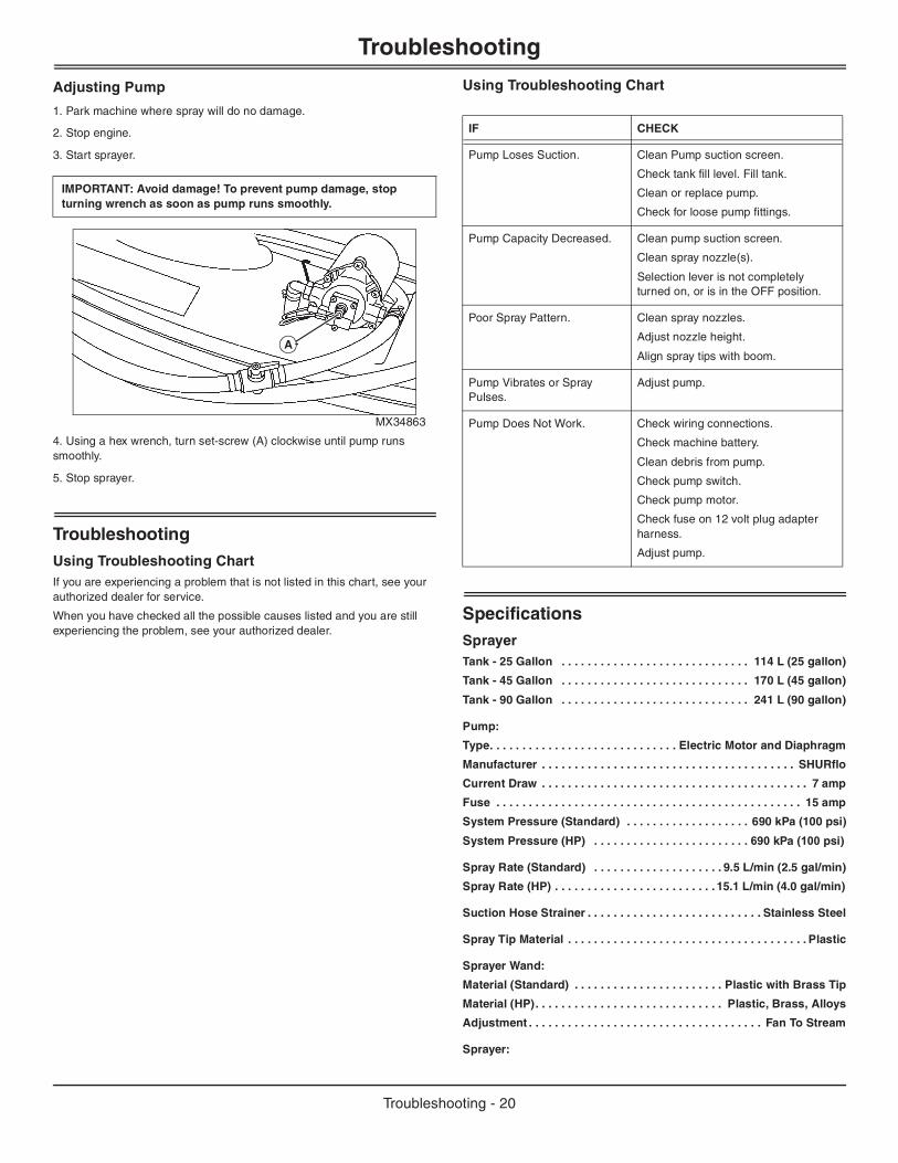
Adjusting Pump
1. Park machine where spray will do no damage.
2. Stop engine.
3. Start sprayer.
MX34863
4. Using a hex wrench, turn set-screw (A) clockwise until pump runs smoothly.
5. Stop sprayer.
TroubleshootingUsing Troubleshooting ChartIf you are experiencing a problem that is not listed in this chart, see your authorized dealer for service.
When you have checked all the possible causes listed and you are still experiencing the problem, see your authorized dealer.
Using Troubleshooting Chart
SpecificationsSprayerTank - 25 Gallon . . . . . . . . . . . . . . . . . . . . . . . . . . . . . 114 L (25 gallon)
Tank - 45 Gallon . . . . . . . . . . . . . . . . . . . . . . . . . . . . . 170 L (45 gallon)
Tank - 90 Gallon . . . . . . . . . . . . . . . . . . . . . . . . . . . . . 241 L (90 gallon)
Pump:
Type. . . . . . . . . . . . . . . . . . . . . . . . . . . . . Electric Motor and Diaphragm
Manufacturer . . . . . . . . . . . . . . . . . . . . . . . . . . . . . . . . . . . . . . . SHURflo
Current Draw . . . . . . . . . . . . . . . . . . . . . . . . . . . . . . . . . . . . . . . . . 7 amp
Fuse . . . . . . . . . . . . . . . . . . . . . . . . . . . . . . . . . . . . . . . . . . . . . . . 15 amp
System Pressure (Standard) . . . . . . . . . . . . . . . . . . . 690 kPa (100 psi)
System Pressure (HP) . . . . . . . . . . . . . . . . . . . . . . . . 690 kPa (100 psi)
Spray Rate (Standard) . . . . . . . . . . . . . . . . . . . . 9.5 L/min (2.5 gal/min)
Spray Rate (HP) . . . . . . . . . . . . . . . . . . . . . . . . . 15.1 L/min (4.0 gal/min)
Suction Hose Strainer . . . . . . . . . . . . . . . . . . . . . . . . . . . Stainless Steel
Spray Tip Material . . . . . . . . . . . . . . . . . . . . . . . . . . . . . . . . . . . . . Plastic
Sprayer Wand:
Material (Standard) . . . . . . . . . . . . . . . . . . . . . . . Plastic with Brass Tip
Material (HP). . . . . . . . . . . . . . . . . . . . . . . . . . . . . Plastic, Brass, Alloys
Adjustment . . . . . . . . . . . . . . . . . . . . . . . . . . . . . . . . . . . . Fan To Stream
Sprayer:
IMPORTANT: Avoid damage! To prevent pump damage, stop turning wrench as soon as pump runs smoothly.
A
IF CHECK
Pump Loses Suction. Clean Pump suction screen.
Check tank fill level. Fill tank.
Clean or replace pump.
Check for loose pump fittings.
Pump Capacity Decreased. Clean pump suction screen.
Clean spray nozzle(s).
Selection lever is not completely turned on, or is in the OFF position.
Poor Spray Pattern. Clean spray nozzles.
Adjust nozzle height.
Align spray tips with boom.
Pump Vibrates or Spray Pulses.
Adjust pump.
Pump Does Not Work. Check wiring connections.
Check machine battery.
Clean debris from pump.
Check pump switch.
Check pump motor.
Check fuse on 12 volt plug adapter harness.
Adjust pump.
Troubleshooting - 20
Getting Quality Service
Spraying Width . . . . . . . . . . . . . . . . . . . . . . . . . . . . . . . . 305 cm (120 in)Weight - 25 Gallon Sprayer:
Empty . . . . . . . . . . . . . . . . . . . . . . . . . . . . . . . . . . . . . . . . . 18 kg (39 lb)
Full . . . . . . . . . . . . . . . . . . . . . . . . . . . . . . . . . . . . . . . . . . 109 kg (239 lb)
Weight - 45 Gallon Sprayer:
Empty . . . . . . . . . . . . . . . . . . . . . . . . . . . . . . . . . . . . . . . . . . 21 kg (46 lb)
Full . . . . . . . . . . . . . . . . . . . . . . . . . . . . . . . . . . . . . . . . . . 184 kg (406 lb)
Weight - 90 Gallon Sprayer:
Empty . . . . . . . . . . . . . . . . . . . . . . . . . . . . . . . . . . . . . . . . . 38 kg (84 lb)
Full . . . . . . . . . . . . . . . . . . . . . . . . . . . . . . . . . . . . . . . . . . 365 kg (804 lb)
Getting Quality ServiceJohn Deere Quality Continues with Quality ServiceJohn Deere provides a process to handle your questions or problems, should they arise, to ensure that product quality continues with quality parts and service support.
Follow the steps below to get answers to any questions you may have about your product.
1. Refer to your attachment and machine operator manuals.
2. In North America or Canada, call John Deere Special Services at 1-888-867-2238 and provide product serial number (if available) and model number.
Getting Quality Service - 21
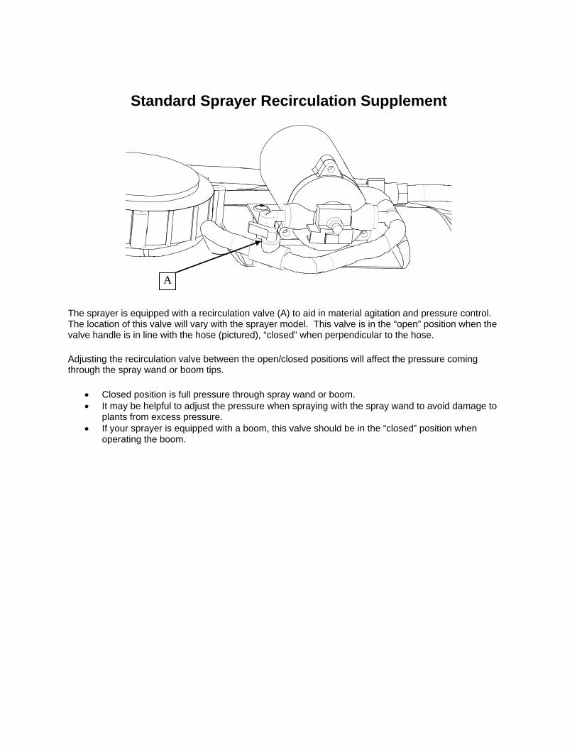
Standard Sprayer Recirculation Supplement
The sprayer is equipped with a recirculation valve (A) to aid in material agitation and pressure control. The location of this valve will vary with the sprayer model. This valve is in the “open” position when the valve handle is in line with the hose (pictured), “closed” when perpendicular to the hose.
Adjusting the recirculation valve between the open/closed positions will affect the pressure coming through the spray wand or boom tips.
Closed position is full pressure through spray wand or boom. It may be helpful to adjust the pressure when spraying with the spray wand to avoid damage to
plants from excess pressure. If your sprayer is equipped with a boom, this valve should be in the “closed” position when
operating the boom.
A