Embed Size (px)
Citation preview

12/8/16 Rev.01
Model ........................................ 40M3L Frequency Range ...................... 7.0-7.3 MHz X 150 kHz Gain ........................................... 6.6 dBi Front to back .............................. 23 dB Beamwidth ............................... E=62° Feed type ................................... Hair pin match Feed Impedance........................ 50 Ohms Unbalanced
Maximum VSWR ....................... 1.3:1 typ. 2:1 max Input Connector ......................... SO-239, Other avl.
Power Handling ......................... 3 kW, Higher avl. Boom Length / Dia ..................... 29.5’ / 3.0 x .125 Wall Element Length / Dia. ................ 51 Ft Turning Radius: ......................... 29 Ft Stacking Distance ...................... Call Mast Size ................................... 2” to 3 ” Nom. Wind area / Survival .................. 9.5 Sq. Ft. / 100 MPH Weight / Ship Wt. ....................... 99 Lbs. / 125 Lbs.
M2 Antenna Systems, Inc. Model No: 40M3L
FEATURES: The 40M3L is a linear loaded 40 meter Yagi designed with 20 years of experience and listening to customer’s needs. The result is a powerful package of clean mechanical design, quality materials, and outstanding performance that will deliver years of enjoyment on the 40 meter band. Mechanically the elements are mounted between 1/2” thick, machined aluminum clamp plates! The Driven element is split and insulated with a 1-1/4 inch solid fiberglass rod and fed with a weather sealed 1:1 balun. All elements use linear loading of 3/16" 6061-T6 aluminum rod to reduce overall length, wind load, and turning radius. The linear loaded sections anchor 10" above the element to reduce inductive cancellation (requiring LESS loading), reduce mechanical stress, and minimize element droop (in the air the antenna is easily mistaken for a 15 or 20 meter Yagi!). Compare performance, construction and durability.... This is not just another 40 meter Yagi!!
SPECIFICATIONS:
*Subtract 2.14 from dBi for dBd
M2 Antenna Systems, Inc. 4402 N. Selland Ave. Fresno, CA 93722 Tel: (559) 432-8873 Fax: (559) 432-3059 Web: www.m2inc.com
©2016 M2 Antenna Systems Incorporated
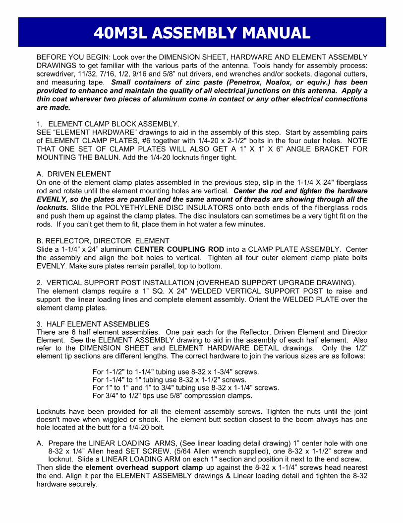
BEFORE YOU BEGIN: Look over the DIMENSION SHEET, HARDWARE AND ELEMENT ASSEMBLY DRAWINGS to get familiar with the various parts of the antenna. Tools handy for assembly process: screwdriver, 11/32, 7/16, 1/2, 9/16 and 5/8” nut drivers, end wrenches and/or sockets, diagonal cutters, and measuring tape. Small containers of zinc paste (Penetrox, Noalox, or equiv.) has been provided to enhance and maintain the quality of all electrical junctions on this antenna. Apply a thin coat wherever two pieces of aluminum come in contact or any other electrical connections are made. 1. ELEMENT CLAMP BLOCK ASSEMBLY. SEE “ELEMENT HARDWARE” drawings to aid in the assembly of this step. Start by assembling pairs of ELEMENT CLAMP PLATES, #6 together with 1/4-20 x 2-1/2" bolts in the four outer holes. NOTE THAT ONE SET OF CLAMP PLATES WILL ALSO GET A 1” X 1” X 6” ANGLE BRACKET FOR MOUNTING THE BALUN. Add the 1/4-20 locknuts finger tight. A. DRIVEN ELEMENT On one of the element clamp plates assembled in the previous step, slip in the 1-1/4 X 24" fiberglass rod and rotate until the element mounting holes are vertical. Center the rod and tighten the hardware EVENLY, so the plates are parallel and the same amount of threads are showing through all the locknuts. Slide the POLYETHYLENE DISC INSULATORS onto both ends of the fiberglass rods and push them up against the clamp plates. The disc insulators can sometimes be a very tight fit on the rods. If you can’t get them to fit, place them in hot water a few minutes. B. REFLECTOR, DIRECTOR ELEMENT Slide a 1-1/4” x 24” aluminum CENTER COUPLING ROD into a CLAMP PLATE ASSEMBLY. Center the assembly and align the bolt holes to vertical. Tighten all four outer element clamp plate bolts EVENLY. Make sure plates remain parallel, top to bottom. 2. VERTICAL SUPPORT POST INSTALLATION (OVERHEAD SUPPORT UPGRADE DRAWING). The element clamps require a 1” SQ. X 24” WELDED VERTICAL SUPPORT POST to raise and support the linear loading lines and complete element assembly. Orient the WELDED PLATE over the element clamp plates. 3. HALF ELEMENT ASSEMBLIES There are 6 half element assemblies. One pair each for the Reflector, Driven Element and Director Element. See the ELEMENT ASSEMBLY drawing to aid in the assembly of each half element. Also refer to the DIMENSION SHEET and ELEMENT HARDWARE DETAIL drawings. Only the 1/2” element tip sections are different lengths. The correct hardware to join the various sizes are as follows: For 1-1/2" to 1-1/4" tubing use 8-32 x 1-3/4" screws. For 1-1/4" to 1" tubing use 8-32 x 1-1/2" screws. For 1" to 1“ and 1” to 3/4" tubing use 8-32 x 1-1/4" screws. For 3/4" to 1/2" tips use 5/8” compression clamps. Locknuts have been provided for all the element assembly screws. Tighten the nuts until the joint doesn't move when wiggled or shook. The element butt section closest to the boom always has one hole located at the butt for a 1/4-20 bolt. A. Prepare the LINEAR LOADING ARMS, (See linear loading detail drawing) 1” center hole with one
8-32 x 1/4” Allen head SET SCREW. (5/64 Allen wrench supplied), one 8-32 x 1-1/2” screw and locknut. Slide a LINEAR LOADING ARM on each 1" section and position it next to the end screw.
Then slide the element overhead support clamp up against the 8-32 x 1-1/4” screws head nearest the end. Align it per the ELEMENT ASSEMBLY drawings & Linear loading detail and tighten the 8-32 hardware securely.
40M3L ASSEMBLY MANUAL

B. Now slide the 1” tube sections over the 7/8 x 9” fiberglass rod insulators. Connect the two sections with 8-32 x 1-1/4" screws and locknuts. Orient the arms as shown and tighten the 8-32 x 1-1/2 screws and locknuts. Be sure the arms are up against the screws closest to the fiberglass rod. THIS IS IMPORTANT SINCE THE ARMS ARE USED FOR DIMENSIONING THE LINEAR LOADING SHORTING BAR POSITION LATER IN THE ASSEMBLY C. Locate the black plastic, 1” x 6” linear loading stabilizer bars. Attach them to the short 3/8” x 1-1/4” x 3” support arm with the 1 inch hole. Use 8-32 x 1” screws and locknuts. Slide these on the SHORT, one inch element sections and position about 3” in from the butt. Now attach the 1-1/4” x 60” element sections. Add the 8-32 x 1-1/2” screws and locknuts but do not tighten until the STABALIZER BAR AND ARM ASSEMBLY ARE IN THE FINAL POSITION. Orient the black stabalizer bar insulators perpendicular to the element coupling holes and the support arms. Secure with 8-32 x 1-1/2” screws and locknuts. Repeat for the other element halves. E. Insert the 3/4 x 48” sections into the swaged 1” sections and secure with 8-32 x 1-1/4 screws and
locknuts. F. Following the DIMENSION SHEET and COMPRESSION CLAMP & TIP ASSEMBLY DETAIL SHEET add the 1/2” tip sections in pairs, noting that each element has different tip lengths. Secure with compression clamps. G. As the outer element sections are being assembled, label each assembly as “REFLECTOR”,
DIRECTOR or “DRIVEN”, ” (according to the 1/2” tips) to avoid mix ups. 4. REFLECTOR AND DIRECTOR ASSEMBLY See ELEMENT HARDWARE drawing. Slide a 1-3/8” x 23-13/16" sleeve onto the 1-1/4” CENTER COUPLING ROD on the ELEMENT CLAMP ASSEMBLY, and align the 1/4” holes. Temporarily pin the sleeve as necessary. Carefully slide a 1-1/2” x 60” element section onto this assembly and align all holes. Insert a 1/4-20 x 2“ bolt and tighten securely with 1/4-20 locknut. Repeat for the other element half. Now add the reflector element outer half element assembly completed in the previous step to the 1-1/2" sections using 8-32 x 1-3/4" screws and locknuts. Repeat for the other element halves. 5. DRIVEN ELEMENT ASSEMBLY See ELEMENT HARDWARE drawings. Slide a 1-3/8” x 23-13/16" sleeve onto each end of the two 1-1/4” fiberglass rods of the remaining element clamp assemblies and align the 1/4” holes. Carefully slide a 1-1/2” x 60” element section onto the two assemblies and align all holes. For both, insert a 1/4-20 x 2“ bolt and secure with 1/4-20 locknuts. BESURE TO INSTALL THE ELEMENT CLAMP PLATE ASSEMBLY WITH THE BALUN ANGLE BRACKET. 6. LINEAR LOADING ASSEMBLY – SEE ASSEMBLY DRAWINGS A. Install a pair of LINEAR LOADING RODS to each element half. Insert a rod through each
STABILIZER INSULATOR BAR and then through a LINEAR LOADING ARM, allowing about 3/4" to extend beyond the arm. Install 8-32 x 1/4" Allen head screws to lock rods in place and add 3/16” shaft retainers for extra safety.
B. Loosely assemble the LINEAR LOADING CLAMP PLATES (SHORTING BAR) pairs using 8-32 x 7/8” screws and locknuts.
C. Slide one set of these shorting bars on the ends of the 3/16” linear loading rods. Measure and mark the position for the shorting bars. Move the bars to that location and tighten one screw to hold position. Insert a short section of BLACK PHILISTRAN CABLE (HPTG1200) through one hole, around strain relief and back thru other hole of shorting bar then add 3/16” cable clip to secure it.
40M3L ASSEMBLY MANUAL

D. Alight the rods and begin to tighten all the 8-32 x 7/8” screws and locknuts. Be sure the rods are parallel and have the same tension. Complete tightening the screws. Repeat for all the element halves.
E. Place the element on a level surface with support post "up." F. Prepare the 1/4” HOOK AND EYE TURNBUCKLES by removing the hook end and running a 1/4-
20 plain nut all the way to the hook. Now replace the hook end into the turnbuckle body and thread it in until just one thread shows inside the body of the turnbuckle. Now adjust the other end EYE of the turnbuckle until just one thread show inside the body.
G. Install the 1/4" HOOK AND EYE TURNBUCKLES in the welded plates at the middle and at the top of the ELEMENT SUPPORTS. Install a CABLE EYE in the EYE of each turnbuckle and route the BLACK HPTG-1200 Philistran cable through the eye and back on itself. Review the element over head support detail drawings for proper routing of the BLACK PHILISTRAN CABLE (HPTG1200) to lock the cable to the clamp. Tension the element overhead support line and linear loading assembly and secure the cable with two cable clips on each line as shown. Repeat for remaining elements.
H. Now adjust the turnbuckles, adjusting so the inner sections are level and tighten the turnbuckle jam nuts. Element tips should droop about 4" to 8". The element will be more stable in the wind if you allow some droop to remain in the element.
Inspect each element for tight hardware and balanced tension on linear loading rods and element assembly supports. Minor tensioning adjustments can be accomplished using the turnbuckles. 7. BOOM ASSEMBLY Use the BOOM HARDWARE drawing as a guide to assemble the boom. At this point it will be helpful to perform the remaining assembly steps with the antenna elevated off the ground (about 3 feet). This can be accomplished by using sawhorses or something similar. Wipe off the swaged ends of each boom section and apply a small amount of Penetrox. Insert the swaged end of the boom sections into the straight piece. Align all of the holes, install the 1/4-20 x 3-1/2" bolts and locknuts, and tighten. A. Install the 5/16” EYEBOLTS to the outer ends of the boom, securing with stainless 5/16” nuts and lock washers. Align the eyes parallel with the boom and tighten. 8. Orient the boom with the eyebolts "up”. Note the location of the REAR end of the antenna and parasitic elements as shown on the DIMENSION SHEET. Using a tape measure and a marking pen or masking tape, place a mark 1/2” in from the rear of the boom. This will be where you position the back edge of the clamp plate for the reflector element. Repeat the same procedure for the other three elements. 9. For ease of element installation, support the boom about 3’ above ground, eyebolts "up." Place the reflector element on the boom. Loosely attach two BOTTOM CRADLES to the bottom of the clamp plates ON THE REFLECTOR AND DIRECTOR using the 1/4-20 x 2-3/4" bolts. (BE SURE TO USE ZINC PASTE ON THESE THREADS) Slide the back edge of the rear plate to your first mark. Level the reflector element and tighten all four bolts EVENLY and firmly. Repeat for the DIRECTOR on the other end of the boom.
40M3L ASSEMBLY MANUAL

10. Mount the DRIVEN ELEMENT assembly in it’s respective position, then attach the two bottom cradles and 1/4-20 hardware. After aligning with the reflector element, tighten the 1/4-20 bolts evenly and firmly. 11. Now take a step back for a moment to observe any misalignment (if any) and the “droop” in each element. Simply look down either the front or back of the boom to do this. If you have not already done so, adjust each turnbuckle until each element droops 6 to 10 inches at the tip. NOTE: The elements are the most stable in wind with a small amount of tip droop. ADJUST FOR LEVEL INNER SECTIONS. After the adjustments have been made, proceed with tightening the 1/4-20 JAMNUT on all the turnbuckles. 12. 1:1 HF BALUN INSTALLATION — SEE ASSEMBLY DRAWINGS AND DIMENSION SHEET Mount the balun to the angle plate on the driven element using a 2-1/2” U-bolt and saddle. Be sure the balun vent hole is down. Do not over tighten as balun damage may occur. 13. INSTALLING THE HAIRPIN (MATCHING ASSEMBLY) A. Apply a little Penetrox to the balun terminal lugs. Remove the nuts holding the 3/8 clamp blocks
and place the balun lead lugs over the studs. Replace the nuts loosely. Apply a little Penetrox to the shorter bent ends of the hairpin tubes. INSERT the tubes into the grooved channels of 3/8” clamp block assemblies on Driven element. Push the tubes through until at least 1/4" extends beyond clamp and then tighten the clamp bolt slightly to hold the tubes from slipping. Rotate the tubes so the bends are level and the long sections are parallel to the boom.
B. Install the 1/4-20 x 1/4” set screws into the ends of the HAIRPIN SHORTING BAR. Insert a 1/4-20 x 2” bolt into the hole of the #52 stainless band clamp from the inside and add the 3/8” x 1” aluminum spacer. Add the shorting bar and the lock nut loosely to hold the assembly together. Open the clamp and set it over the boom about 60 inches from the driven element. Now slide the assembly to the ends of the hairpin tubes and insert the end into the shorting bar. ( lubricant like WD-40 or zinc paste will let the shorting bar slide easier on the tubes. Position the shorting bar 38 inches from the driven element. Align the assembly, and tighten the band clamp. Next tighten the nut securing the shorting bar and finally tighten the set screws onto the tube. NOTE: IF YOU CAN DO FINAL VSWR MEASURMENTS AND ADJUSTMENTS DURING THE FINAL INSTALLATION, DO NOT TIGHTEN THE SET SCREWS YET. SEE THE NOTE AT THE BOTTOM OF THE “DIMENSION SHEET”
C. Now return the to balun end of the hairpin assembly and final tighten the bolts holding the tube ends and the balun leads.
14. Attach the BOOM TO MAST PLATE at the balance point, using the two large 3” U-bolts, 3/8-16 stainless lockwashers, and nuts. Align plate to vertical and tighten nuts. For they should be attached in a way to allow the boom to be balanced on your tower / mast. 15. OVERHEAD BOOM SUPPORT SYSTEM. A. Attach one end of the 5/16" Dacron cord to the rear eyebolt using two turns around the eyebolt and a series of three half hitches or equivalent knots. Finish with about 6 inches of cord after the knots. Without cutting the cord, do the same at the front eyebolt. Pull on the knots HARD to SET them. Seal ends with heat or flame to prevent fraying. Tape the excess 6 inches of cord back to main cord tightly with black vinyl electricians tape.
40M3L ASSEMBLY MANUAL

B. TEMPORARILY insert a 2 inch U-bolt through the turnbuckle plate and add two nuts so about 1/2 inch of the threads stick out. Insert this assembly through the top set of 2” U-bolt holes in the boom to mast plate from the boom side and add two more nuts. Open the two turnbuckles up until just a thread or two from each end shows inside the body of the turnbuckle. Hook the turnbuckles into the holes at the edge of the turnbuckle plate. Equalize the Dacron cord over the plate and cut it. Take two wraps of the cord through the eye of the rear turnbuckle, PULL the cord as tight as possible and make the knots as before. Repeat for the front cord section and turnbuckle. Cut off any excess over one foot long and again seal and tape back to the main cord. C. Now DISASSEMBLE the U-bolt from the boom to mast plate. Before installation, if possible, install a short temporary mast, attach turnbuckle, and let the overhead guy system support the boom overnight. The Dacron cord DOES NOT STRETCH UNDER THIS LOAD but it's weave will take a SET and the boom may droop just a bit. If your boom droops again following final adjustments, check your knots. They may be may be slipping. D. After final installation of the antenna, the turnbuckle plate, installed loosely with a 2” U-bolt, is raised up the mast. When the boom is straight the U-bolt is tightened. This should place the turnbuckle plate 4 to 6 feet above the boom. Do the final boom straightening with the turnbuckles and safety wire to preserve adjustments. 16. Check ALL hardware for tightness. Check ALL element sections, especially tip sections, for correct placement. Make any final adjustments to linear loading tension. 17. Attach the feedline section to the balun. Route it towards the boom to mast plate. Secure at regular intervals with tape or nylon ties. 18. When mounting this antenna on a tower or mast with other antennas there may be interaction. In general VHF and/ or UHF antennas mounted for HORIZONTAL POLARITY should be AT LEAST 40 inches above or below the antenna. Use good quality 50 Ohm coaxial cable to feed the antenna and be sure your tower and rotator system can handle the wind loading and vertical weight of this antenna.
THIS COMPLETES ANTENNA ASSEMBLY
M2 ANTENNA SYSTEMS, INC. 4402 N. SELLAND AVE.
FRESNO, CA 93722 (559) 432-8873 FAX (559) 432-3059
www.m2inc.com Email: [email protected]
40M3L ASSEMBLY MANUAL

40M3L DIMENSION SHEET

2M4 ASSEMBLY MANUAL OVERHEAD SUPPORT UPGARDE DETAIL

2M4 ASSEMBLY MANUAL LINEAR LOADING DETAIL
ELE
ME
NT
OV
ER
HE
AD
SU
PP
OR
T C
LAM
P

40M3L ASSEMBLY DETAIL

40M3L ASSEMBLY DETAIL

GENERIC COMPRESSION CLAMP DETAIL

40M3L PARTS & HARDWARE UNBAGED ITEMS DESCRIPTION ............................................................................................ QTY Assembly manual ........................................................................................ 1 Insulator, 1-1/4” x 24" fiberglass rod ........................................................... 1 Coupling, center 1-1/4” x 24” alum. Rod. .................................................... 2 Boom to mast plate, 1/4” x 8” x 8" alum. ..................................................... 1 Balun, 1:1, 3-30 MHz SO-239 conn.. ........................................................ 1 Tension Line, Phyllistrand 1200 HTPG, 36” ................................................ 6 Support post, 1” x 1” x 24” SQ. Tube (M2AVR0050) .................................. 3 Element Overhead Support, HPTG1200 x 28’……………………………………………………...3 Zinc Paste ( Penetrox, Noalox or equivalent) container ............................. 1 Dacron cord, 5/16” x 30 feet ........................................................................ 1 ALUMINUM TUBING DESCRIPTION ............................................................................................ QTY Boom section, 3” x .125” x 180" SOE (Drilled both ends) ........................... 1 Boom section, 3” x .125” x 180" STR .......................................................... 1 Sleeve, 1-3/8” x .058” x 23-13/16" .............................................................. 6 Element butt section, 1-1/2” x .058” x 60" SOE ......................................... 6 Element section, 1-1/4” x .058” x 60” SOE ................................................ 6 Element section, 1.0” x .058” x 60” SOE ..................................................... 6 Element section, 1.0” x .058” x 24” SOE ..................................................... 6 Element section, 3/4” x .049” x 48" SOE ..................................................... 6 Element tip section, 1/2” x .049” x 61.50” .................................................... 2 Element tip section, 1/2” x .049” x 47.50” .................................................... 2 Element tip section, 1/2” x .049” x 42.50” .................................................... 2 Hair pin tube, 3/8 x 55” ................................................................................ 2 ALUMINUM ROD DESCRIPTION ............................................................................................ QTY Linear loading rod 3/16” x 114" alum. ........................................................ 6 Linear loading rod, 3/16 x 111" alum. ........................................................ 6 BAG #1 Linear loading arm, 3/8” x 1-1/4 ” x 3-3/4”, alum. 1” hole ............................ 12 Element Overhead Support Clamp, 3/8” x 3‐3/4” ........................................ 6 BAG #2 Insulator, stabilizer bar, 1/4” x 1” x 6” ABS. ................................................. 6 Support arm, for stabilizer bar 3/8” x 1-1/4” x 2-7/8”, alum. 1” hole ............ 6 BAG #3 Disc insulator, 3/8” x 2" polyethylene, 1-1/4" hole ...................................... 2 Clamp Block, hairpin, 1/4” x 1-1/4” x 1”” alum., 3/8” groove ....................... 4 Balun mounting angle bracket, 1” x 1” x 6” alum. ........................................ 1 Band clamp, #52 with hole .......................................................................... 1 Turnbuckle plate 3/16 x 2 x 5” , alum. ........................................................ 1 Turnbuckle, 1/4-20 x 6”, hook and eye ........................................................ 12 Turnbuckle, 5/16” hook and eye .................................................................. 2 Eyebolt, 5/16” x 5” #10843 ......................................................................... 2 Cable eye, 1/4” ............................................................................................ 4 Nylon ties, 12” .............................................................................................. 5 Spacer, 3/8 x 1” ( used in hairpin assembly) ............................................... 1

BAG #4 Shorting bar, 1/4” x 3/4” x 6" ....................................................................... 12 Strain Relief, 1/2 x 1/2 blk delrin .................................................................. 6 Shorting bar, hairpin, 1/2 x 1/2 x 5” ........................................................... 1 BAG #5 Saddle Clamp, 1/2” x 1.0” x 4" alum. ........................................................... 6 Element Clamp plate, 1/2” x 3” x 6", 5/8” radius, alum #6 ........................... 6 BAG #6 Fiberglass rod, 7/8” x 9” with 4 holes .......................................................... 6 BAG #7 U-bolt, 3" ...................................................................................................... 2 U-bolt, 2-1/2" ............................................................................................... 1 U-bolt, 2", HEAVY DUTY ............................................................................. 4 U-bolt, 2” standard ....................................................................................... 1 BAG #8 Nut, 3/8-16 stainless .................................................................................... 14 Lock washer, 3/8" split ring stainless .......................................................... 14 Nut, 5/16-18, stainless ................................................................................. 6 Lock washer, 5/16" split ring, stainless ....................................................... 4 Bolt, 1/4-20 x 3-1/2" stainless ...................................................................... 8 Bolt, 1/4-20 x 3-1/4 stainless ....................................................................... 6 Bolt, 1/4-20 x 2-3/4" stainless ...................................................................... 12 Bolt, 1/4-20 x 2-1/2" stainless ...................................................................... 14 Bolt, 1/4-20 x 2.0" stainless ......................................................................... 5 Set screws, 1/4-20 x 1/4”,ss ........................................................................ 2 Nut, 1/4-20”, stainless ................................................................................. 6 Nut, 1/4-20 locking, stainless ...................................................................... 27 Allen wrench, 1/8” ........................................................................................ 1 BAG #9 5/8” Compression clamp ............................................................................. 6 Screw, 8-32 x 1-3/4” panhead, stainless ..................................................... 12 Screw, 8-32 x 1-1/2" panhead, stainless ..................................................... 36 Screw, 8-32 x 1-1/4" panhead, stainless ..................................................... 36 Screw, 8-32 x 1.0" panhead, stainless ........................................................ 42 Screw, 8-32 x 1/2" panhead, stainless ........................................................ 6 Set screw, 8-32 x 1/4” stainless ................................................................. 24 Nut, 8-32, stainless ...................................................................................... 6 Nut, 8-32 locking, stainless ......................................................................... 126 Shaft retainer, 3/16” stainless ...................................................................... 24 Push tube 3/8” x 3" alum. ............................................................................ 1 Allen wrench 5/64” ....................................................................................... 2 Cable Clips, 1/8” .......................................................................................... 30 Small Cable Eyes, 1/8” ................................................................................ 12
M2 ANTENNA SYSTEMS, INC. 4402 N. SELLAND AVE.
FRESNO, CA 93722 (559) 432-8873 FAX (559) 432-3059
www.m2inc.com Email: [email protected]
40M3L PARTS & HARDWARE