Embed Size (px)
Citation preview
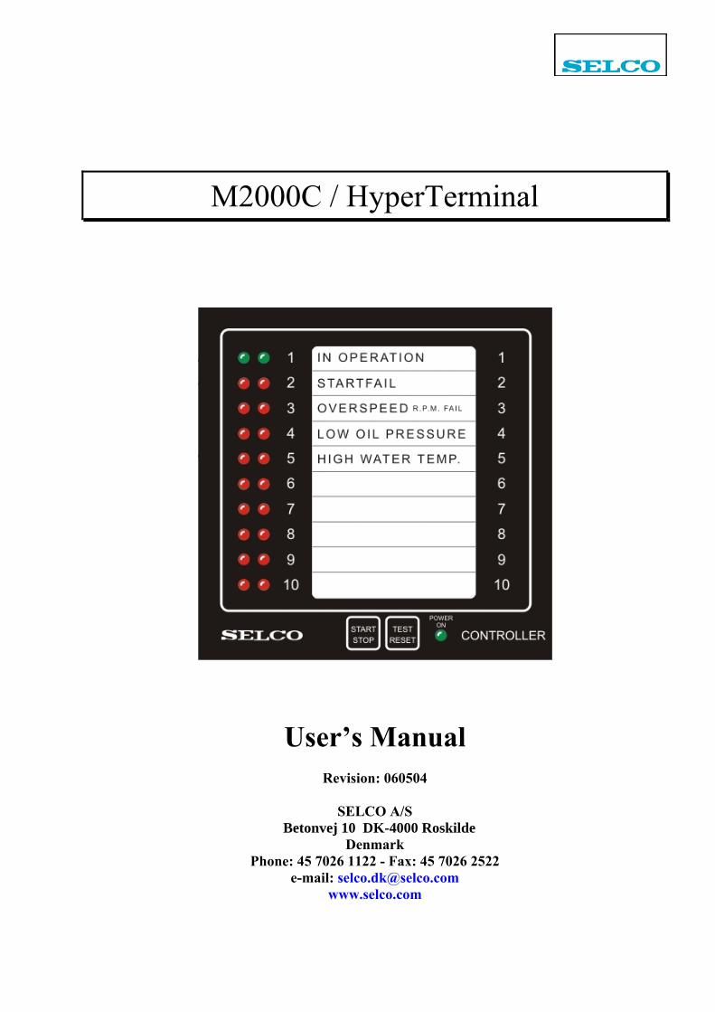
M2000C / HyperTerminal
User’s Manual
Revision: 060504
SELCO A/S Betonvej 10 DK-4000 Roskilde
Denmark Phone: 45 7026 1122 - Fax: 45 7026 2522
e-mail: [email protected] www.selco.com
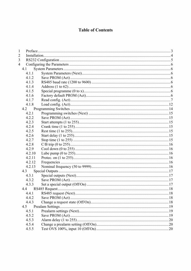
Table of Contents 1 Preface..........................................................................................................................................3 2 Installation....................................................................................................................................4 3 RS232 Configuration ...................................................................................................................5 4 Configuring the Parameters .........................................................................................................6
4.1 System Parameters ...............................................................................................................6 4.1.1 System Parameters (Next)............................................................................................6 4.1.2 Save PROM (Act) ........................................................................................................6 4.1.3 RS485 baud rate (1200 to 9600) ..................................................................................6 4.1.4 Address (1 to 62)..........................................................................................................6 4.1.5 Special programme (0 to x)..........................................................................................6 4.1.6 Factory default PROM (Act)........................................................................................6 4.1.7 Read config. (Act)........................................................................................................7 4.1.8 Load config. (Act)......................................................................................................12
4.2 Programming Switches ......................................................................................................14 4.2.1 Programming switches (Next) ...................................................................................15 4.2.2 Save PROM (Act) ......................................................................................................15 4.2.3 Start attempts (1 to 255).............................................................................................15 4.2.4 Crank time (1 to 255) .................................................................................................15 4.2.5 Rest time (1 to 255)....................................................................................................15 4.2.6 Start delay (1 to 255)..................................................................................................15 4.2.7 Stop time (1 to 255) ...................................................................................................15 4.2.8 C/B trip (0 to 255)......................................................................................................16 4.2.9 Cool down (0 to 255) .................................................................................................16 4.2.10 Lube pump (0 to 255).................................................................................................16 4.2.11 Protec. on (1 to 255)...................................................................................................16 4.2.12 Frequencies ................................................................................................................16 4.2.13 Nominal frequency (50 to 9999)................................................................................16
4.3 Special Outputs ..................................................................................................................17 4.3.1 Special outputs (Next)................................................................................................17 4.3.2 Save PROM (Act) ......................................................................................................17 4.3.3 Set a special output (Off/On) .....................................................................................17
4.4 RS485 Request...................................................................................................................18 4.4.1 RS485 request (Next).................................................................................................18 4.4.2 Save PROM (Act) ......................................................................................................18 4.4.3 Change a request state (Off/On).................................................................................18
4.5 Prealam Settings.................................................................................................................19 4.5.1 Prealarm settings (Next).............................................................................................19 4.5.2 Save PROM (Act) ......................................................................................................19 4.5.3 Alarm delay (1 to 255) ...............................................................................................20 4.5.4 Change a prealarm setting (Off/On)...........................................................................20 4.5.5 Test OVS 100%, input 10 (Off/On) ...........................................................................20
SELCO A/S M2000C / HyperTerminal Manual
Revision: 060504 Page 3 of 20
1 Preface This document describes how to configure the SELCO M2000C Engine Controller using the included RS232 cable and a PC running Windows HyperTerminal.
SELCO A/S M2000C / HyperTerminal Manual
Revision: 060504 Page 4 of 20
2 Installation Plug one end of the supplied RS232 cable into the grey RJ plug located on the side of the M2000C (next to the supply). The other end of the cable (with the DB9 plug) connects to a PC COM port (COM1 is used in this manual). Do not attach the power supply to the M2000 before the HyperTerminal application is running. No damage will occur, but it might prevent the M2000C form initializing the communication.
SELCO A/S M2000C / HyperTerminal Manual
Revision: 060504 Page 5 of 20
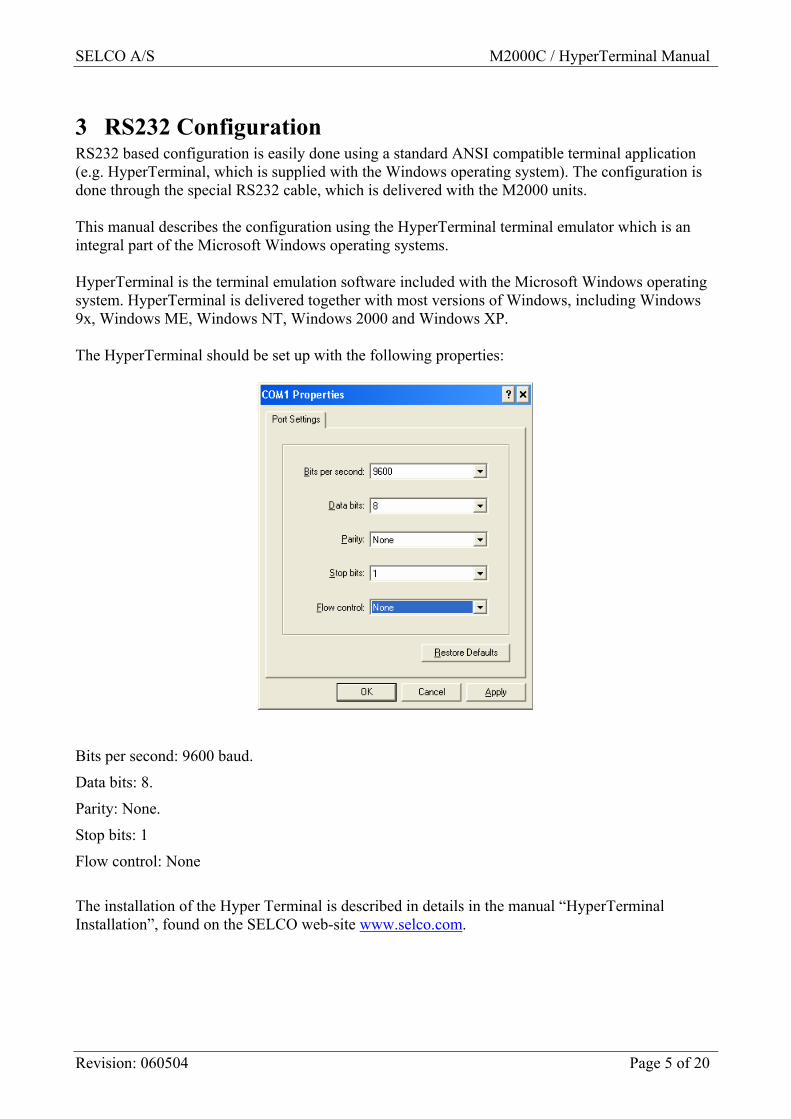
3 RS232 Configuration RS232 based configuration is easily done using a standard ANSI compatible terminal application (e.g. HyperTerminal, which is supplied with the Windows operating system). The configuration is done through the special RS232 cable, which is delivered with the M2000 units. This manual describes the configuration using the HyperTerminal terminal emulator which is an integral part of the Microsoft Windows operating systems. HyperTerminal is the terminal emulation software included with the Microsoft Windows operating system. HyperTerminal is delivered together with most versions of Windows, including Windows 9x, Windows ME, Windows NT, Windows 2000 and Windows XP. The HyperTerminal should be set up with the following properties:
Bits per second: 9600 baud.
Data bits: 8.
Parity: None.
Stop bits: 1
Flow control: None
The installation of the Hyper Terminal is described in details in the manual “HyperTerminal Installation”, found on the SELCO web-site www.selco.com.
SELCO A/S M2000C / HyperTerminal Manual
Revision: 060504 Page 6 of 20
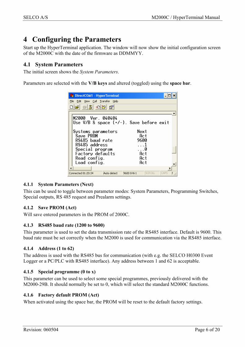
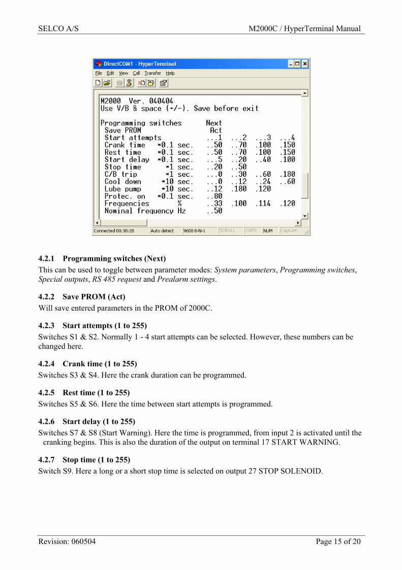
4 Configuring the Parameters Start up the HyperTerminal application. The window will now show the initial configuration screen of the M2000C with the date of the firmware as DDMMYY.
4.1 System Parameters The initial screen shows the System Parameters. Parameters are selected with the V/B keys and altered (toggled) using the space bar.
4.1.1 System Parameters (Next) This can be used to toggle between parameter modes: System Parameters, Programming Switches, Special outputs, RS 485 request and Prealarm settings.
4.1.2 Save PROM (Act) Will save entered parameters in the PROM of 2000C.
4.1.3 RS485 baud rate (1200 to 9600) This parameter is used to set the data transmission rate of the RS485 interface. Default is 9600. This baud rate must be set correctly when the M2000 is used for communication via the RS485 interface.
4.1.4 Address (1 to 62) The address is used with the RS485 bus for communication (with e.g. the SELCO H0300 Event Logger or a PC/PLC with RS485 interface). Any address between 1 and 62 is acceptable.
4.1.5 Special programme (0 to x) This parameter can be used to select some special programmes, previously delivered with the M2000-29B. It should normally be set to 0, which will select the standard M2000C functions.
4.1.6 Factory default PROM (Act) When activated using the space bar, the PROM will be reset to the default factory settings.
SELCO A/S M2000C / HyperTerminal Manual
Revision: 060504 Page 7 of 20
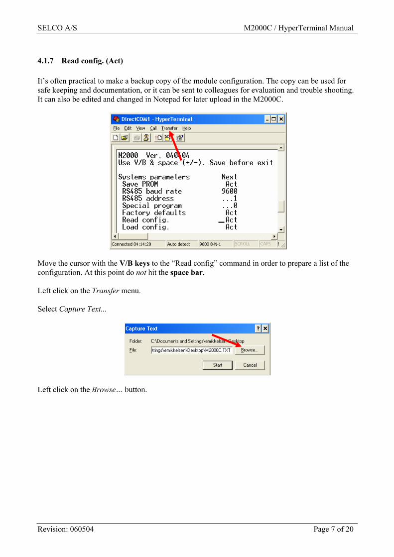
4.1.7 Read config. (Act) It’s often practical to make a backup copy of the module configuration. The copy can be used for safe keeping and documentation, or it can be sent to colleagues for evaluation and trouble shooting. It can also be edited and changed in Notepad for later upload in the M2000C.
Move the cursor with the V/B keys to the “Read config” command in order to prepare a list of the configuration. At this point do not hit the space bar. Left click on the Transfer menu. Select Capture Text...
Left click on the Browse… button.
SELCO A/S M2000C / HyperTerminal Manual
Revision: 060504 Page 8 of 20
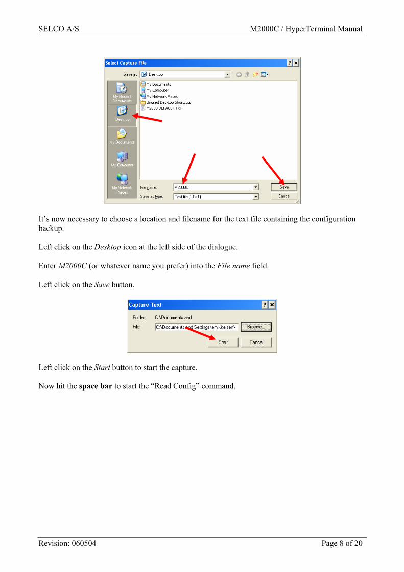
It’s now necessary to choose a location and filename for the text file containing the configuration backup. Left click on the Desktop icon at the left side of the dialogue. Enter M2000C (or whatever name you prefer) into the File name field. Left click on the Save button.
Left click on the Start button to start the capture. Now hit the space bar to start the “Read Config” command.
SELCO A/S M2000C / HyperTerminal Manual
Revision: 060504 Page 9 of 20
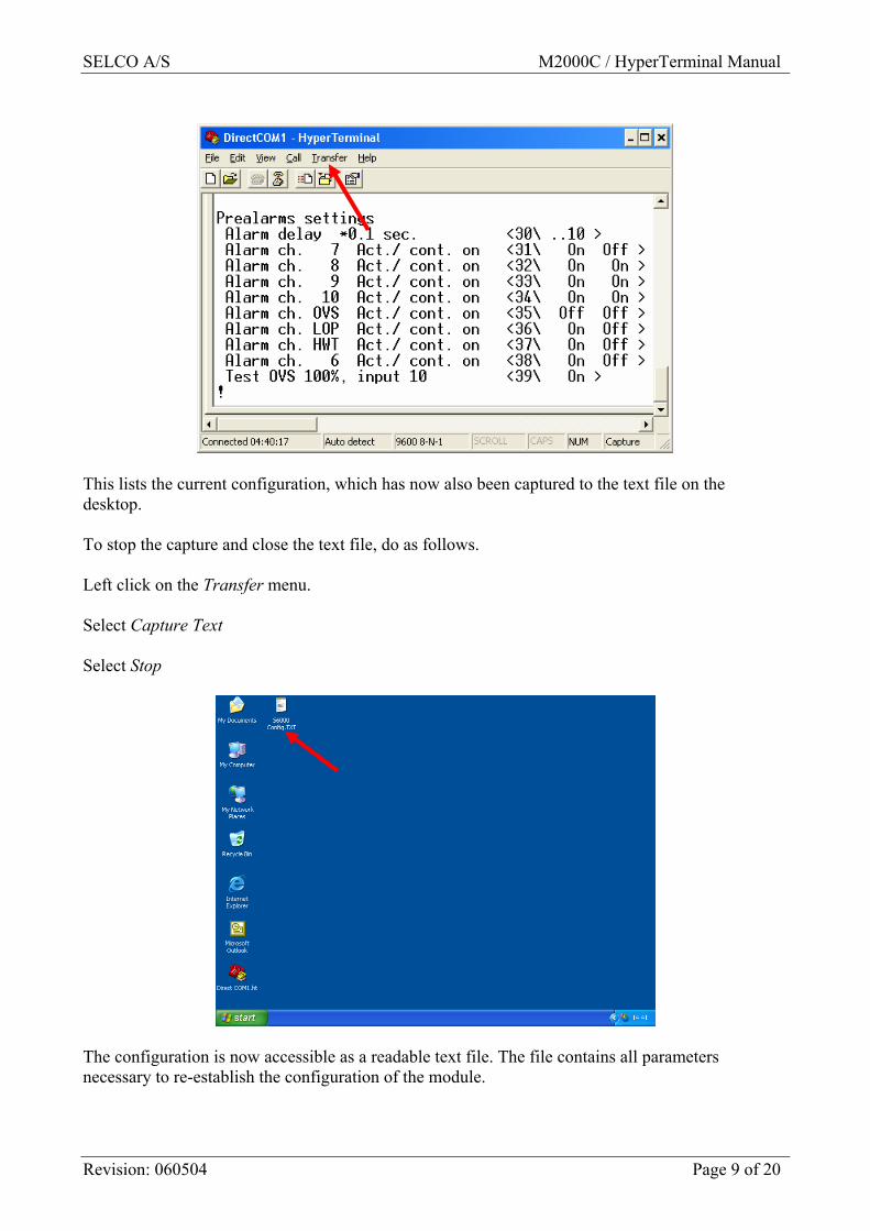
This lists the current configuration, which has now also been captured to the text file on the desktop. To stop the capture and close the text file, do as follows. Left click on the Transfer menu. Select Capture Text Select Stop
The configuration is now accessible as a readable text file. The file contains all parameters necessary to re-establish the configuration of the module.
SELCO A/S M2000C / HyperTerminal Manual
Revision: 060504 Page 10 of 20
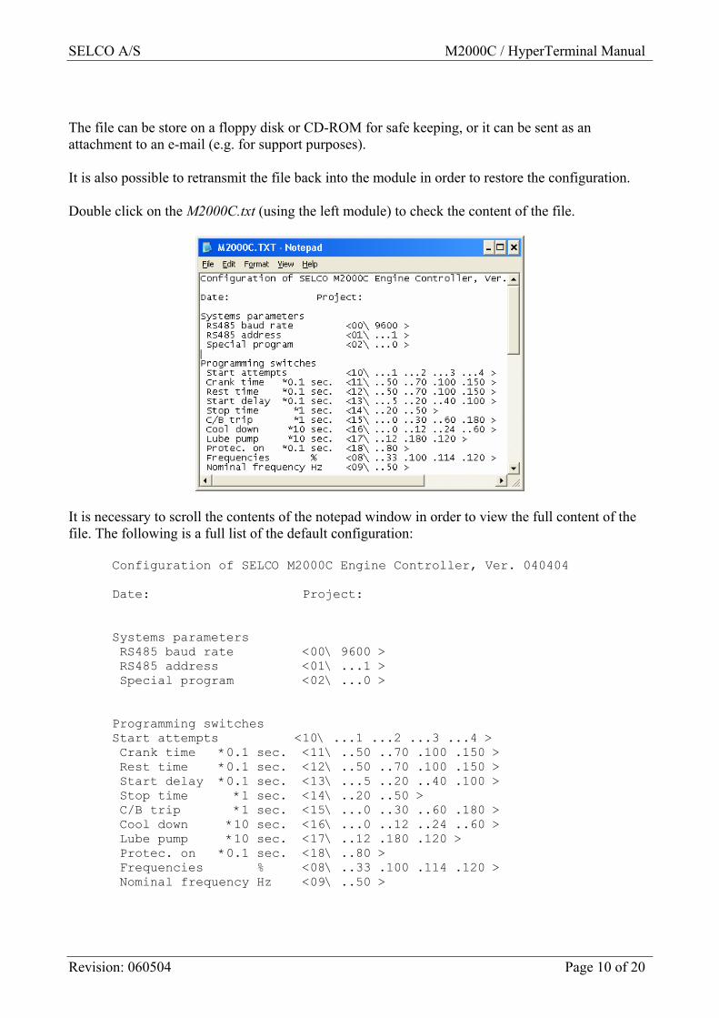
The file can be store on a floppy disk or CD-ROM for safe keeping, or it can be sent as an attachment to an e-mail (e.g. for support purposes). It is also possible to retransmit the file back into the module in order to restore the configuration. Double click on the M2000C.txt (using the left module) to check the content of the file.
It is necessary to scroll the contents of the notepad window in order to view the full content of the file. The following is a full list of the default configuration:
Configuration of SELCO M2000C Engine Controller, Ver. 040404 Date: Project: Systems parameters RS485 baud rate <00\ 9600 > RS485 address <01\ ...1 > Special program <02\ ...0 > Programming switches Start attempts <10\ ...1 ...2 ...3 ...4 > Crank time *0.1 sec. <11\ ..50 ..70 .100 .150 > Rest time *0.1 sec. <12\ ..50 ..70 .100 .150 > Start delay *0.1 sec. <13\ ...5 ..20 ..40 .100 > Stop time *1 sec. <14\ ..20 ..50 > C/B trip *1 sec. <15\ ...0 ..30 ..60 .180 > Cool down *10 sec. <16\ ...0 ..12 ..24 ..60 > Lube pump *10 sec. <17\ ..12 .180 .120 > Protec. on *0.1 sec. <18\ ..80 > Frequencies % <08\ ..33 .100 .114 .120 > Nominal frequency Hz <09\ ..50 >
SELCO A/S M2000C / HyperTerminal Manual
Revision: 060504 Page 11 of 20
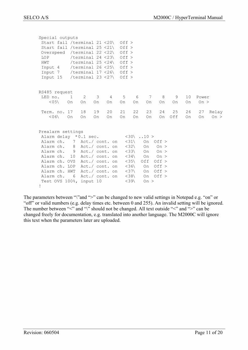
Special outputs Start fail /terminal 21 <20\ Off > Start fail /terminal 25 <21\ Off > Overspeed /terminal 22 <22\ Off > LOP /terminal 24 <23\ Off > HWT /terminal 25 <24\ Off > Input 4 /terminal 26 <25\ Off > Input 7 /terminal 17 <26\ Off > Input 15 /terminal 23 <27\ Off > RS485 request LED no. 1 2 3 4 5 6 7 8 9 10 Power <05\ On On On On On On On On On On On > Term. no. 17 18 19 20 21 22 23 24 25 26 27 Relay <06\ On On On On On On On On Off On On On > Prealarm settings Alarm delay *0.1 sec. <30\ ..10 > Alarm ch. 7 Act./ cont. on <31\ On Off > Alarm ch. 8 Act./ cont. on <32\ On On > Alarm ch. 9 Act./ cont. on <33\ On On > Alarm ch. 10 Act./ cont. on <34\ On On > Alarm ch. OVS Act./ cont. on <35\ Off Off > Alarm ch. LOP Act./ cont. on <36\ On Off > Alarm ch. HWT Act./ cont. on <37\ On Off > Alarm ch. 6 Act./ cont. on <38\ On Off > Test OVS 100%, input 10 <39\ On > !
The parameters between “\”and “>” can be changed to new valid settings in Notepad e.g. “on” or “off” or valid numbers (e.g. delay times etc. between 0 and 255). An invalid setting will be ignored. The number between “<” and “\” should not be changed. All text outside “<” and “>” can be changed freely for documentation, e.g. translated into another language. The M2000C will ignore this text when the parameters later are uploaded.
SELCO A/S M2000C / HyperTerminal Manual
Revision: 060504 Page 12 of 20
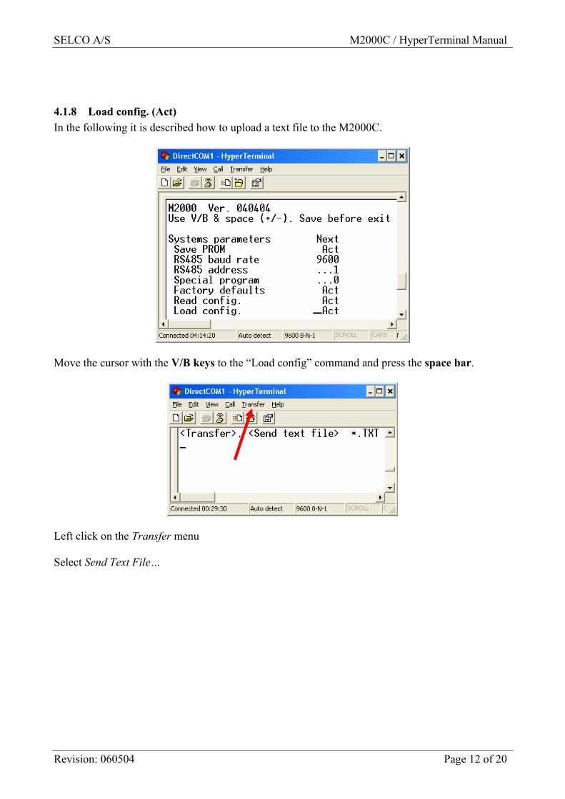
4.1.8 Load config. (Act) In the following it is described how to upload a text file to the M2000C.
Move the cursor with the V/B keys to the “Load config” command and press the space bar.
Left click on the Transfer menu Select Send Text File…
SELCO A/S M2000C / HyperTerminal Manual
Revision: 060504 Page 13 of 20
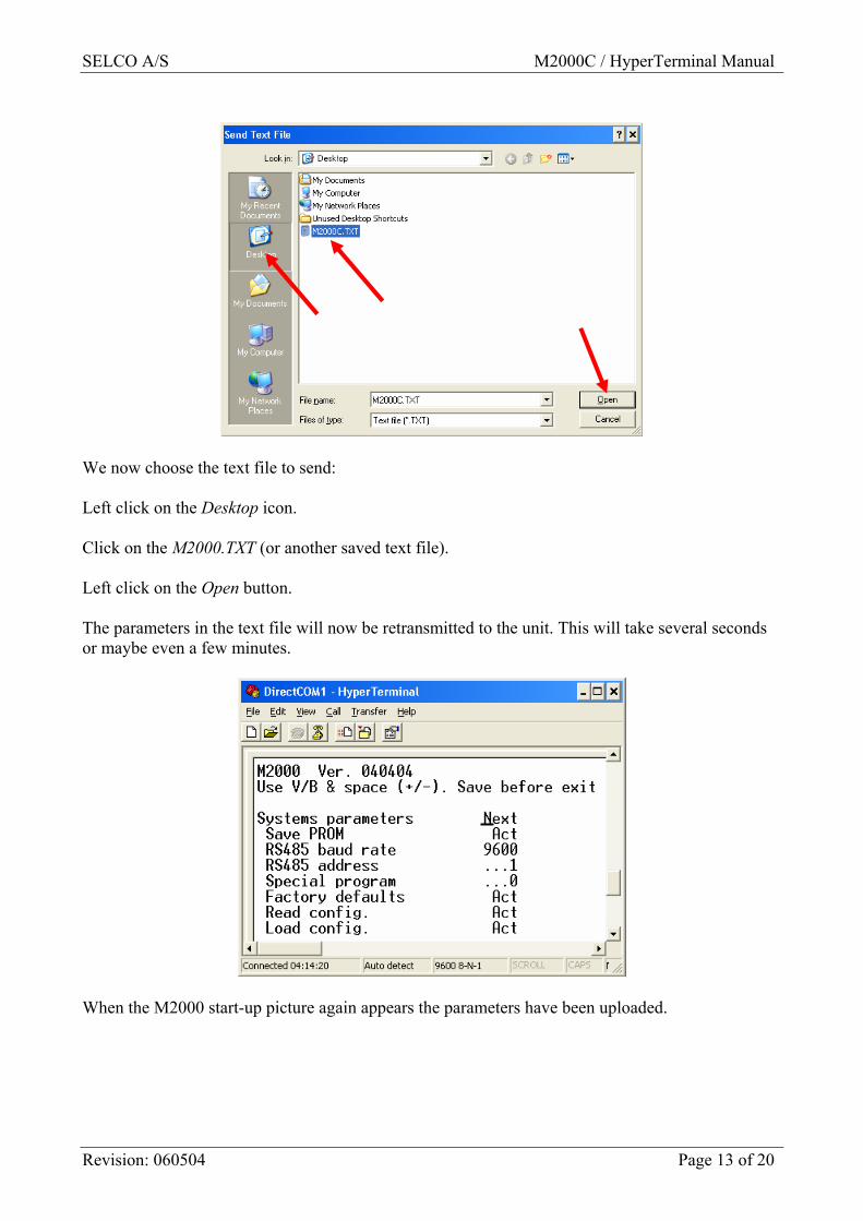
We now choose the text file to send: Left click on the Desktop icon. Click on the M2000.TXT (or another saved text file). Left click on the Open button. The parameters in the text file will now be retransmitted to the unit. This will take several seconds or maybe even a few minutes.
When the M2000 start-up picture again appears the parameters have been uploaded.
SELCO A/S M2000C / HyperTerminal Manual
Revision: 060504 Page 14 of 20
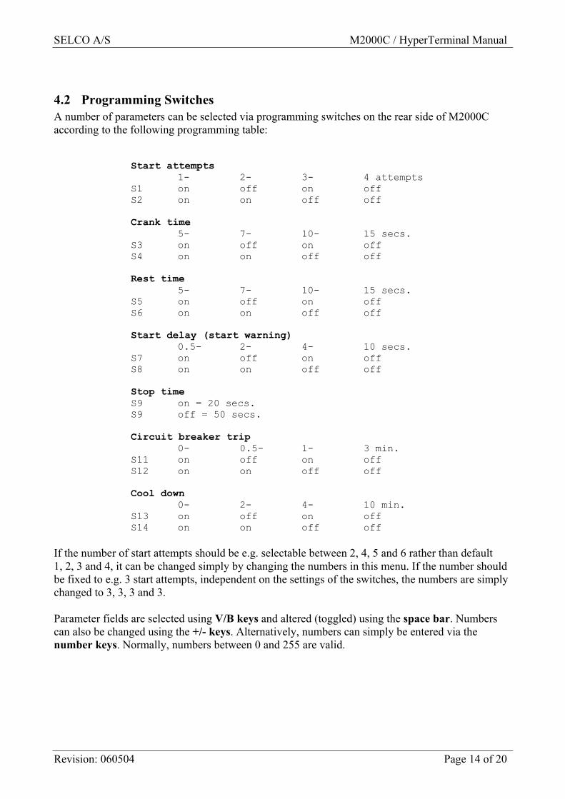
4.2 Programming Switches A number of parameters can be selected via programming switches on the rear side of M2000C according to the following programming table:
Start attempts 1- 2- 3- 4 attempts S1 on off on off S2 on on off off Crank time 5- 7- 10- 15 secs. S3 on off on off S4 on on off off Rest time 5- 7- 10- 15 secs. S5 on off on off S6 on on off off Start delay (start warning) 0.5- 2- 4- 10 secs. S7 on off on off S8 on on off off Stop time S9 on = 20 secs. S9 off = 50 secs. Circuit breaker trip 0- 0.5- 1- 3 min. S11 on off on off S12 on on off off Cool down 0- 2- 4- 10 min. S13 on off on off S14 on on off off
If the number of start attempts should be e.g. selectable between 2, 4, 5 and 6 rather than default 1, 2, 3 and 4, it can be changed simply by changing the numbers in this menu. If the number should be fixed to e.g. 3 start attempts, independent on the settings of the switches, the numbers are simply changed to 3, 3, 3 and 3. Parameter fields are selected using V/B keys and altered (toggled) using the space bar. Numbers can also be changed using the +/- keys. Alternatively, numbers can simply be entered via the number keys. Normally, numbers between 0 and 255 are valid.
SELCO A/S M2000C / HyperTerminal Manual
Revision: 060504 Page 15 of 20
4.2.1 Programming switches (Next) This can be used to toggle between parameter modes: System parameters, Programming switches, Special outputs, RS 485 request and Prealarm settings.
4.2.2 Save PROM (Act) Will save entered parameters in the PROM of 2000C.
4.2.3 Start attempts (1 to 255) Switches S1 & S2. Normally 1 - 4 start attempts can be selected. However, these numbers can be changed here.
4.2.4 Crank time (1 to 255) Switches S3 & S4. Here the crank duration can be programmed.
4.2.5 Rest time (1 to 255) Switches S5 & S6. Here the time between start attempts is programmed.
4.2.6 Start delay (1 to 255) Switches S7 & S8 (Start Warning). Here the time is programmed, from input 2 is activated until the
cranking begins. This is also the duration of the output on terminal 17 START WARNING.
4.2.7 Stop time (1 to 255) Switch S9. Here a long or a short stop time is selected on output 27 STOP SOLENOID.
SELCO A/S M2000C / HyperTerminal Manual
Revision: 060504 Page 16 of 20
4.2.8 C/B trip (0 to 255) Switches S11 & S12. With the engine running this is the time from input 2 is being deactivated until the generator circuit breaker is tripped via output 26. This is used in connection with emergency generator installations, where emergency supply is wanted for a pre-defined time after normal supply is restored.
4.2.9 Cool down (0 to 255) Switches S13 & S14. Here the time is programmed where the diesel engine runs without load before it is stopped.
4.2.10 Lube pump (0 to 255) Terminal 25 (AUXILIARY LUBE PUMP normally becomes active for 2 min every 30 min., when the engine is stopped. This is used for continuous lubrication. Immediately after stop, the first lubrication period is 20 min. These times of 12, 180 and 120 * 10 sec. can be changed to any number between 0 and 255 * 10 sec.
4.2.11 Protec. on (1 to 255) For a number of alarm inputs (terminals 4, 5, 6, 7, 13, 14 and 15) shut-down is enabled 8 sec. crank disconnect. This “protection on” time of 0.1 * 80 sec. can be changed using this parameter.
4.2.12 Frequencies Normally, when M2000C is used together with a tacho voltage detector or together with a magnetic pick-up, the frequency limits must be defined. “Crank disconnect” frequency is normally 33% of nominal speed. “Test overspeed” frequency is normally 100%. When terminal 10 (OVERSPEED) is connected to plus an overspeed test will be at 100%. Overspeed frequency is normally 114% 8 sec. after start (crank disconnect). Overspeed frequency is normally 120% the first 8.sec. after start (crank disconnect) These values of 33, 100, 114 and 120% can be changed with this parameter.
4.2.13 Nominal frequency (50 to 9999) When used together with a SELCO M0500 Tacho Detector Input Terminal 9 can be used to select a nominal frequency of 50Hz or 60Hz. When used directly with a magnetic pick-up, the nominal frequency of the pick-up can be entered via the RS232 interface using this parameter. Nominal frequencies up to 10 KHz are possible.
SELCO A/S M2000C / HyperTerminal Manual
Revision: 060504 Page 17 of 20
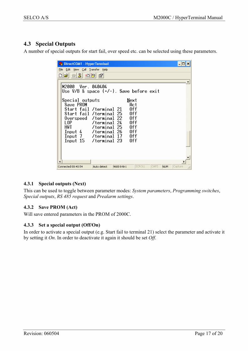
4.3 Special Outputs A number of special outputs for start fail, over speed etc. can be selected using these parameters.
4.3.1 Special outputs (Next) This can be used to toggle between parameter modes: System parameters, Programming switches, Special outputs, RS 485 request and Prealarm settings.
4.3.2 Save PROM (Act) Will save entered parameters in the PROM of 2000C.
4.3.3 Set a special output (Off/On) In order to activate a special output (e.g. Start fail to terminal 21) select the parameter and activate it by setting it On. In order to deactivate it again it should be set Off.
SELCO A/S M2000C / HyperTerminal Manual
Revision: 060504 Page 18 of 20
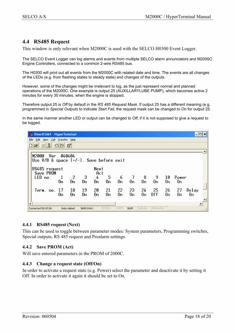
4.4 RS485 Request This window is only relevant when M2000C is used with the SELCO H0300 Event Logger. The SELCO Event Logger can log alarms and events from multiple SELCO alarm annunciators and M2000C Engine Controllers, connected to a common 2-wire RS485 bus. The H0300 will print out all events from the M2000C with related date and time. The events are all changes of the LEDs (e.g. from flashing states to steady state) and changes of the outputs. However, some of the changes might be irrelevant to log, as the just represent normal and planned operations of the M2000C. One example is output 25 (AUXILLARYLUBE PUMP), which becomes active 2 minutes for every 30 minutes, when the engine is stopped. Therefore output 25 is Off by default in the RS 485 Request Mask. If output 25 has a different meaning (e.g. programmed in Special Outputs to indicate Start Fail, the request mask can be changed to On for output 25. In the same manner another LED or output can be changed to Off, if it is not supposed to give a request to be logged.
4.4.1 RS485 request (Next) This can be used to toggle between parameter modes: System parameters, Programming switches, Special outputs, RS 485 request and Prealarm settings.
4.4.2 Save PROM (Act) Will save entered parameters in the PROM of 2000C.
4.4.3 Change a request state (Off/On) In order to activate a request state (e.g. Power) select the parameter and deactivate it by setting it Off. In order to activate it again it should be set to On.
SELCO A/S M2000C / HyperTerminal Manual
Revision: 060504 Page 19 of 20
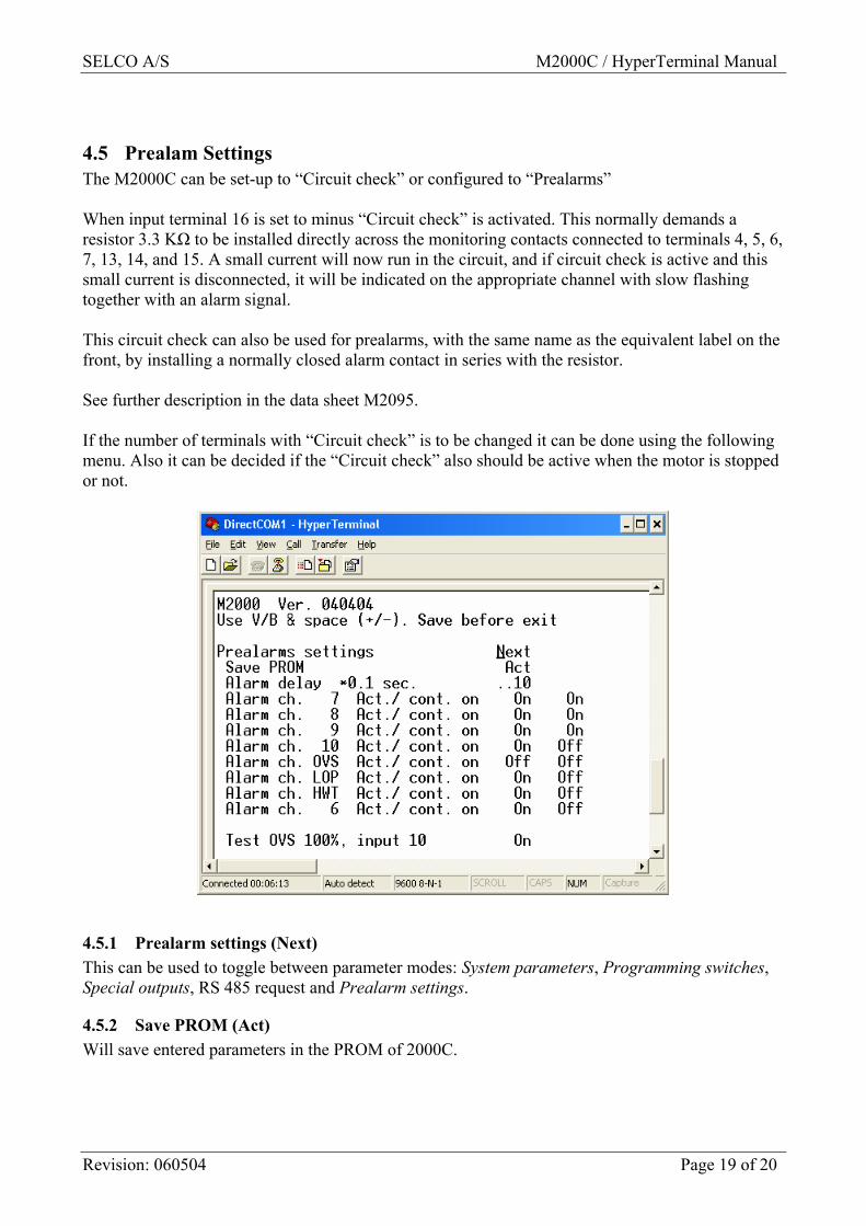
4.5 Prealam Settings The M2000C can be set-up to “Circuit check” or configured to “Prealarms” When input terminal 16 is set to minus “Circuit check” is activated. This normally demands a resistor 3.3 KΩ to be installed directly across the monitoring contacts connected to terminals 4, 5, 6, 7, 13, 14, and 15. A small current will now run in the circuit, and if circuit check is active and this small current is disconnected, it will be indicated on the appropriate channel with slow flashing together with an alarm signal. This circuit check can also be used for prealarms, with the same name as the equivalent label on the front, by installing a normally closed alarm contact in series with the resistor. See further description in the data sheet M2095. If the number of terminals with “Circuit check” is to be changed it can be done using the following menu. Also it can be decided if the “Circuit check” also should be active when the motor is stopped or not.
4.5.1 Prealarm settings (Next) This can be used to toggle between parameter modes: System parameters, Programming switches, Special outputs, RS 485 request and Prealarm settings.
4.5.2 Save PROM (Act) Will save entered parameters in the PROM of 2000C.
SELCO A/S M2000C / HyperTerminal Manual
Revision: 060504 Page 20 of 20
4.5.3 Alarm delay (1 to 255) Normally, the delay for alarms is 1 sec, (10 * 0.1 sec.). If a different delay is wanted it can be entered using this parameter.
4.5.4 Change a prealarm setting (Off/On) In order to include e.g. overspeed (OVS) as one of the inputs for prealarms, do the following: Choose “Alarm ch. OVS Act./ cont. on” and set in On at the first parameter. If the prealarm also should be active when the motor is stopped also the second parameter should be set to On.
4.5.5 Test OVS 100%, input 10 (Off/On) Normally, when used with the SELCO M0500 Thacho Detector or directly with a magnetic pick-up, input terminal 10 connected to plus will give an overspeed test will be obtained at 100% of nominal speed. If this test is to be avoided, the parameter should be set to Off.