Embed Size (px)
Citation preview
Delivering Breakthrough Datacenter System Innovation – Experience What’s Inside !
Intel® Server System M20MYP1UR
Technical Product Specification An overview of product features, functions,
architecture, and support specifications.
Rev 1.0
May 2020
M20MYP1UR

2
<Blank page>

Intel® Server System M20MYP1UR Technical Product Specification
1
Document Revision History
Date Revision Changes
May 2020 1.0 First release.

Intel® Server System M20MYP1UR Technical Product Specification
2
Disclaimers
Intel technologies’ features and benefits depend on system configuration and may require enabled hardware, software, or service
activation. Performance varies depending on system configuration. No computer system can be absolutely secure. Check with your
system manufacturer or retailer or learn more at intel.com.
You may not use or facilitate the use of this document in connection with any infringement or other legal analysis concerning Intel
products described herein. You agree to grant Intel a non-exclusive, royalty-free license to any patent claim thereafter drafted which
includes subject matter disclosed herein.
No license (express or implied, by estoppel or otherwise) to any intellectual property rights is granted by this document.
The products described may contain design defects or errors known as errata which may cause the product to deviate from
published specifications. Current characterized errata are available on request.
Intel disclaims all express and implied warranties, including without limitation, the implied warranties of merchantability, fitness
for a particular purpose, and non-infringement, as well as any warranty arising from course of performance, course of dealing, or
usage in trade.
Copies of documents which have an order number and are referenced in this document may be obtained by calling 1-800-548-4725
or by visiting www.intel.com/design/literature.htm.
Intel, the Intel logo, Xeon, and Intel Optane are trademarks of Intel Corporation or its subsidiaries in the U.S. and/or other countries.
*Other names and brands may be claimed as the property of others.
© Intel Corporation
Intel® Server System M20MYP1UR Technical Product Specification
3
Table of Contents
1. Introduction .................................................................................................................................................................. 8
2. Server System Family Overview............................................................................................................................... 9
2.1 Server System Features Set .......................................................................................................................................... 9
2.2 System Feature Identification ................................................................................................................................... 11
2.3 Server Board Features Overview ............................................................................................................................. 12
2.4 System Dimensional Data ........................................................................................................................................... 16
2.4.1 Chassis dimensions ....................................................................................................................................................... 16
2.4.2 Top Cover Emboss Dimensions ............................................................................................................................... 16
2.4.3 Pull-Out Tab Label Emboss Dimensions ..................................................................................................................... 17
2.5 System Cable Routing Channels .............................................................................................................................. 18
2.6 Available Rack and Cabinet Mounting Kit Options .......................................................................................... 18
2.7 System Level Environmental Limits ....................................................................................................................... 20
2.8 System Packaging .......................................................................................................................................................... 21
3. Processor Support .................................................................................................................................................... 22
3.1 Processor Heat Sink Module (PHM) Assembly and Processor Socket Assembly ............................... 22
3.2 Processor Thermal Design Power (TDP) Support ............................................................................................ 24
3.3 Processor Family Overview ........................................................................................................................................ 24
3.3.1 Supported Technologies ............................................................................................................................................ 26
3.4 Processor Population Rules ....................................................................................................................................... 26
3.5 Processor Initialization Error Summary ................................................................................................................ 27
4. Memory Support ....................................................................................................................................................... 29
4.1 Memory Subsystem Architecture ............................................................................................................................ 29
4.2 Supported Memory ....................................................................................................................................................... 29
4.3 General Support Rules for Memory ........................................................................................................................ 30
4.3.1 DIMM Population Guidelines for Best Performance ........................................................................................ 32
4.4 Memory RAS Features .................................................................................................................................................. 33
4.4.1 DIMM Population Rules and BIOS Setup for Memory RAS ........................................................................... 34
5. System Power ............................................................................................................................................................ 35
5.1 Closed Loop System Throttling (CLST) ................................................................................................................. 35
5.2 Smart Ride Through (SmaRT) Throttling .............................................................................................................. 35
5.3 Power Supply Specification Overview................................................................................................................... 35
5.3.1 Power Supply Module Efficiency ............................................................................................................................. 36
5.3.2 Power Cord Specifications ......................................................................................................................................... 36
5.4 AC Power Supply Features ......................................................................................................................................... 37
5.4.1 Power Supply Status LED ........................................................................................................................................... 37
5.4.2 Protection Circuits ......................................................................................................................................................... 37
6. Thermal Management ............................................................................................................................................. 38
6.1 Thermal Operation and Configuration Requirements .................................................................................... 38
6.1.1 Memory Slot Population Requirements ............................................................................................................... 38
6.2 Thermal Management Overview .............................................................................................................................. 40
Intel® Server System M20MYP1UR Technical Product Specification
4
6.3 System Fans ..................................................................................................................................................................... 40
6.4 Power Supply Module Fan ......................................................................................................................................... 41
6.5 FRUSDR Utility ................................................................................................................................................................. 41
7. Platform Management ............................................................................................................................................. 42
7.1 Management Feature Set Overview ....................................................................................................................... 42
7.1.1 IPMI 2.0 Features Overview ....................................................................................................................................... 42
7.1.2 Non-IPMI Features Overview..................................................................................................................................... 43
7.2 Platform Management Features and Functions ................................................................................................ 44
7.2.1 Power Subsystem .......................................................................................................................................................... 44
7.2.2 Advanced Configuration and Power Interface (ACPI) ..................................................................................... 44
7.2.3 Watchdog Timer ............................................................................................................................................................. 45
7.2.4 System Event Log (SEL) ............................................................................................................................................... 45
7.3 Sensor Monitoring ......................................................................................................................................................... 46
7.3.1 Sensor Re-arm Behavior ............................................................................................................................................. 46
7.3.2 Thermal Monitoring ...................................................................................................................................................... 46
7.4 Standard Fan Management ........................................................................................................................................ 47
7.4.1 Fan Domains ..................................................................................................................................................................... 47
7.4.2 Fan Redundancy Detection ........................................................................................................................................ 47
7.4.3 Thermal and Acoustic Management ...................................................................................................................... 48
7.4.4 Thermal Sensor Input to Fan Speed Control ..................................................................................................... 48
7.5 Memory Thermal Management ................................................................................................................................ 49
7.6 Power Management Bus (PMBus*) .......................................................................................................................... 50
7.7 Component Fault LED Control ................................................................................................................................. 50
8. PCI Express (PCIe*) Support ................................................................................................................................... 51
8.1 PCIe* Enumeration and Allocation ......................................................................................................................... 51
8.2 Non-Transparent Bridge ............................................................................................................................................. 52
9. System I/O ................................................................................................................................................................. 53
9.1 PCIe* Add-in Card Support ........................................................................................................................................ 53
9.2 System Storage ............................................................................................................................................................... 54
9.2.1 Front Drive Bay Support .............................................................................................................................................. 54
9.2.2 Hot Swap Drive Carriers .............................................................................................................................................. 54
9.2.3 Hot Swap Backplane Support ................................................................................................................................... 56
9.2.4 M.2 Storage Device Support ...................................................................................................................................... 58
9.2.5 SATA Support .................................................................................................................................................................. 60
9.2.6 Embedded Software RAID Support ........................................................................................................................ 62
9.3 Network Interface ........................................................................................................................................................... 64
9.4 USB Support ..................................................................................................................................................................... 65
9.4.1 Front USB Ports .............................................................................................................................................................. 65
9.4.2 Rear USB Ports ................................................................................................................................................................ 65
9.4.3 Internal USB 3.0 Type-A Connector ....................................................................................................................... 65
9.5 Video Support ................................................................................................................................................................. 66
10. Front Control Panel .................................................................................................................................................. 67
Intel® Server System M20MYP1UR Technical Product Specification
5
10.1 Control Panel Features ................................................................................................................................................ 67
Appendix A. Getting Help .......................................................................................................................................... 70
Appendix B. Integration and Usage Tips ................................................................................................................ 71
Appendix C. Post Code Diagnostic LED Decoder ................................................................................................. 72
C.1 Early POST Memory Initialization MRC Diagnostic Codes ............................................................................ 73
C.2 BIOS POST Progress Codes ....................................................................................................................................... 75
Appendix D. Post Code Errors .................................................................................................................................. 82
D.1 POST Error Beep Codes .............................................................................................................................................. 88
Appendix E. System Cable Routing Diagrams ...................................................................................................... 90
Appendix F. Statement of Volatility........................................................................................................................ 91
Appendix G. Product Regulatory Compliance....................................................................................................... 93
Appendix H. Reference Documents ......................................................................................................................... 98
Appendix I. Glossary ................................................................................................................................................. 99
List of Figures
Figure 1. Intel® Server System M20MYP1UR .................................................................................................................................... 8
Figure 2. System components overview.......................................................................................................................................... 11
Figure 3. Back panel feature identification ..................................................................................................................................... 11
Figure 4. Front control panel feature identification ................................................................................................................... 11
Figure 5. Intel® Server Board M20MYP1UR architectural block diagram .......................................................................... 12
Figure 6. Server board components overview .............................................................................................................................. 13
Figure 7. Intel® Light Guided Diagnostics - DIMM fault LEDs .................................................................................................. 14
Figure 8. Jumper block identification ............................................................................................................................................... 14
Figure 9. Intel® Light Guided Diagnostics – LED identification ............................................................................................... 15
Figure 10. Chassis dimensions ............................................................................................................................................................ 16
Figure 11. Top cover emboss dimensions ...................................................................................................................................... 16
Figure 12. Pull-out tab location .......................................................................................................................................................... 17
Figure 13. Pull-out tab label emboss dimensions ....................................................................................................................... 17
Figure 14. System cable routing channels...................................................................................................................................... 18
Figure 15. Processor socket assembly and protective dust cover ....................................................................................... 22
Figure 16. Processor heat sink module (PHM) component and processor socket reference diagram ................. 23
Figure 17. Processor heat sink module (PHM) sub-assembly ................................................................................................ 23
Figure 18. Fully assembled processor heat sink module (PHM) ........................................................................................... 23
Figure 19. Intel® Xeon® Processor Scalable Identification ....................................................................................................... 24
Figure 20. Memory sub-system architecture ................................................................................................................................. 29
Figure 21. Intel® Server System M20MYP1UR DIMM slot layout .......................................................................................... 31
Figure 22. DIMM population guidelines ........................................................................................................................................... 32
Figure 23. DIMM population example for memory rank sparing .......................................................................................... 34
Figure 24. DIMM population example for memory mirroring ................................................................................................ 34
Intel® Server System M20MYP1UR Technical Product Specification
6
Figure 25. Power supply module identification ........................................................................................................................... 35
Figure 26. AC power cord specification ........................................................................................................................................... 36
Figure 27. Thermal management system features ..................................................................................................................... 38
Figure 28. System DIMM population layout ................................................................................................................................... 39
Figure 29. DIMM Blank ............................................................................................................................................................................ 39
Figure 30. System Fans ........................................................................................................................................................................... 41
Figure 31. High-level fan speed control process ......................................................................................................................... 49
Figure 32. Two systems connected through an NTB ................................................................................................................. 52
Figure 33. PCIe* add-in card support ............................................................................................................................................... 53
Figure 34. Front hot swap drive bays................................................................................................................................................ 54
Figure 35. Drive carrier removal .......................................................................................................................................................... 54
Figure 36. 3.5” drive carrier assembly .............................................................................................................................................. 55
Figure 37. Mounting a 2.5" SSD to a 3.5" drive carrier ............................................................................................................... 55
Figure 38. Drive tray LED identification ........................................................................................................................................... 56
Figure 39. 4 x 3.5" hot swap backplane, front side ..................................................................................................................... 57
Figure 40. 4 x 3.5" hot swap backplane, back side ...................................................................................................................... 57
Figure 41. Backplane placement ........................................................................................................................................................ 57
Figure 42. M.2 connectors ..................................................................................................................................................................... 59
Figure 43. Mini-SAS HD connectors location ................................................................................................................................ 62
Figure 44. SATA ESRT2 RAID 5 upgrade key ................................................................................................................................. 64
Figure 45. Network interface connectors ........................................................................................................................................ 64
Figure 46. Network interface controller (NIC) port LED definition ....................................................................................... 64
Figure 47. Front USB ports .................................................................................................................................................................... 65
Figure 48. Rear USB connector ports ............................................................................................................................................... 65
Figure 49. Internal USB 3.0 Type-A Connector ............................................................................................................................ 65
Figure 50. Front control panel features ........................................................................................................................................... 67
Figure 51. POST diagnostic LED location and definition .......................................................................................................... 72
Figure 52. System cable routing diagram ....................................................................................................................................... 90
List of Tables
Table 1. Intel® Server System M20MYP1UR features ................................................................................................................... 9
Table 2. System environmental limits summary.......................................................................................................................... 20
Table 3. 1st Gen Intel® Xeon® Processor Scalable Family Feature Comparison .............................................................. 25
Table 4. 2nd Gen Intel® Xeon® Processor Scalable Family Feature Comparison ............................................................. 25
Table 5. Mixed processor configurations error summary ........................................................................................................ 28
Table 6. 1st Gen Intel® Xeon® Processor Scalable Family DDR4 SDRAM DIMM Support Guidelines ..................... 29
Table 7. 2nd Gen Intel® Xeon® Processor Scalable Family \DDR4 SDRAM DIMM Support Guidelines .................. 30
Table 8. Maximum Supported SDRAM DIMM Speeds by SKU Level in MT/s (Mega Transfers/second) .............. 30
Table 9. Memory RAS Features ........................................................................................................................................................... 33
Table 10. 750 W AC power supply option efficiency (80 PLUS* Platinum) ...................................................................... 36
Intel® Server System M20MYP1UR Technical Product Specification
7
Table 11. AC power cord specifications .......................................................................................................................................... 36
Table 12. LED indicators ........................................................................................................................................................................ 37
Table 13. Over current protection ..................................................................................................................................................... 37
Table 14. Over voltage protection (OVP) limits ............................................................................................................................ 37
Table 15. Power control sources ........................................................................................................................................................ 44
Table 16. ACPI power states ................................................................................................................................................................. 44
Table 17. Component fault LEDs ........................................................................................................................................................ 50
Table 18. CPU – PCIe* port routing ................................................................................................................................................... 51
Table 19. Riser root port mapping ..................................................................................................................................................... 53
Table 20. Drive status LED states ....................................................................................................................................................... 56
Table 21. Drive activity LED states ..................................................................................................................................................... 56
Table 22. SATA and sSATA Controller Feature Support .......................................................................................................... 60
Table 23. SATA and sSATA controller BIOS utility setup options ........................................................................................ 61
Table 24. Network interface controller (NIC) LED Definition .................................................................................................. 64
Table 25. Supported video resolutions ........................................................................................................................................... 66
Table 26. System status LED state definitions.............................................................................................................................. 68
Table 27. Power/sleep LED functional states ............................................................................................................................... 69
Table 28. POST progress code LED example ................................................................................................................................ 72
Table 29. MRC progress codes ............................................................................................................................................................ 73
Table 30. MRC Fatal Error Codes ........................................................................................................................................................ 74
Table 31. POST progress codes .......................................................................................................................................................... 75
Table 32. POST error codes and messages ................................................................................................................................... 83
Table 33. POST error beep codes ...................................................................................................................................................... 88
Table 34. Integrated BMC beep codes ............................................................................................................................................. 89
Table 35. Volatile and non-volatile components on the Server Board (IPC – MYP1USVB) ...................................... 91
Table 36. 1U 1-slot PCIe* riser card (iPN – H39531-xxx) ......................................................................................................... 91
Table 37. 1U 4 x 3.5” hot swap backplane (iPN – G97162-XXX)........................................................................................... 91
Table 38. Intel® Remote Management Module Lite accessory option (iPC – AXXRMM4LITE2) ............................... 91
Table 39. Reference documents ......................................................................................................................................................... 98
Intel® Server System M20MYP1UR Technical Product Specification
8
1. Introduction
This Technical Product Specification (TPS) provides a high-level overview of the features, functions,
architecture and support specifications of the Intel® Server System M20MYP1UR.
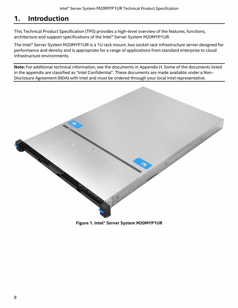
The Intel® Server System M20MYP1UR is a 1U rack mount, two socket rack infrastructure server designed for
performance and density and is appropriate for a range of applications from standard enterprise to cloud
infrastructure environments.
Note: For additional technical information, see the documents in Appendix H. Some of the documents listed
in the appendix are classified as “Intel Confidential”. These documents are made available under a Non-
Disclosure Agreement (NDA) with Intel and must be ordered through your local Intel representative.
Figure 1. Intel® Server System M20MYP1UR
Intel® Server System M20MYP1UR Technical Product Specification
9
2. Server System Family Overview
This chapter provides an overview of the system and chassis features, dimensions, and environmental and
packaging specifications.
2.1 Server System Features Set
The following table provides a high-level overview of the server system features and available options
supported by the Intel Server System M20MYP1UR.
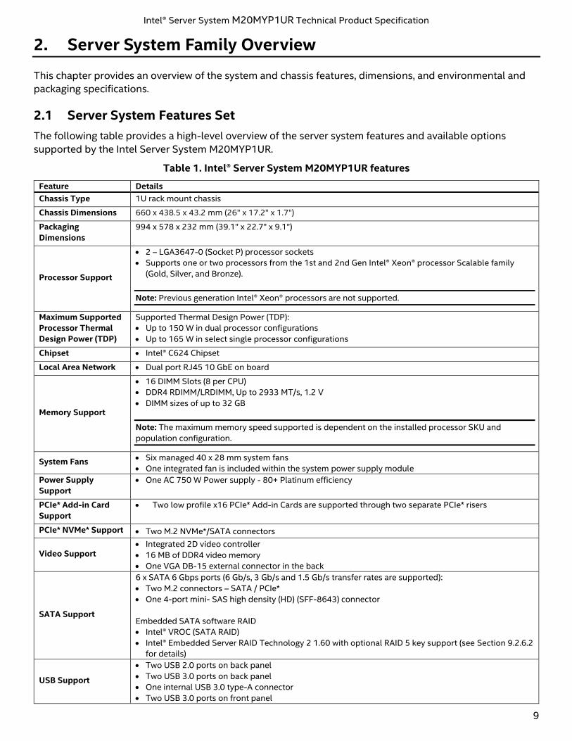
Table 1. Intel® Server System M20MYP1UR features
Feature Details
Chassis Type 1U rack mount chassis
Chassis Dimensions 660 x 438.5 x 43.2 mm (26” x 17.2” x 1.7”)
Packaging
Dimensions
994 x 578 x 232 mm (39.1” x 22.7” x 9.1”)
Processor Support
• 2 – LGA3647-0 (Socket P) processor sockets
• Supports one or two processors from the 1st and 2nd Gen Intel® Xeon® processor Scalable family
(Gold, Silver, and Bronze).
Note: Previous generation Intel® Xeon® processors are not supported.
Maximum Supported
Processor Thermal
Design Power (TDP)
Supported Thermal Design Power (TDP):
• Up to 150 W in dual processor configurations
• Up to 165 W in select single processor configurations
Chipset • Intel® C624 Chipset
Local Area Network • Dual port RJ45 10 GbE on board
Memory Support
• 16 DIMM Slots (8 per CPU)
• DDR4 RDIMM/LRDIMM, Up to 2933 MT/s, 1.2 V
• DIMM sizes of up to 32 GB
Note: The maximum memory speed supported is dependent on the installed processor SKU and
population configuration.
System Fans • Six managed 40 x 28 mm system fans
• One integrated fan is included within the system power supply module
Power Supply
Support
• One AC 750 W Power supply - 80+ Platinum efficiency
PCIe* Add-in Card
Support
• Two low profile x16 PCIe* Add-in Cards are supported through two separate PCIe* risers
PCIe* NVMe* Support • Two M.2 NVMe*/SATA connectors
Video Support • Integrated 2D video controller
• 16 MB of DDR4 video memory
• One VGA DB-15 external connector in the back
SATA Support
6 x SATA 6 Gbps ports (6 Gb/s, 3 Gb/s and 1.5 Gb/s transfer rates are supported):
• Two M.2 connectors – SATA / PCIe*
• One 4-port mini- SAS high density (HD) (SFF-8643) connector
Embedded SATA software RAID
• Intel® VROC (SATA RAID)
• Intel® Embedded Server RAID Technology 2 1.60 with optional RAID 5 key support (see Section 9.2.6.2
for details)
USB Support
• Two USB 2.0 ports on back panel
• Two USB 3.0 ports on back panel
• One internal USB 3.0 type-A connector
• Two USB 3.0 ports on front panel
Intel® Server System M20MYP1UR Technical Product Specification
10
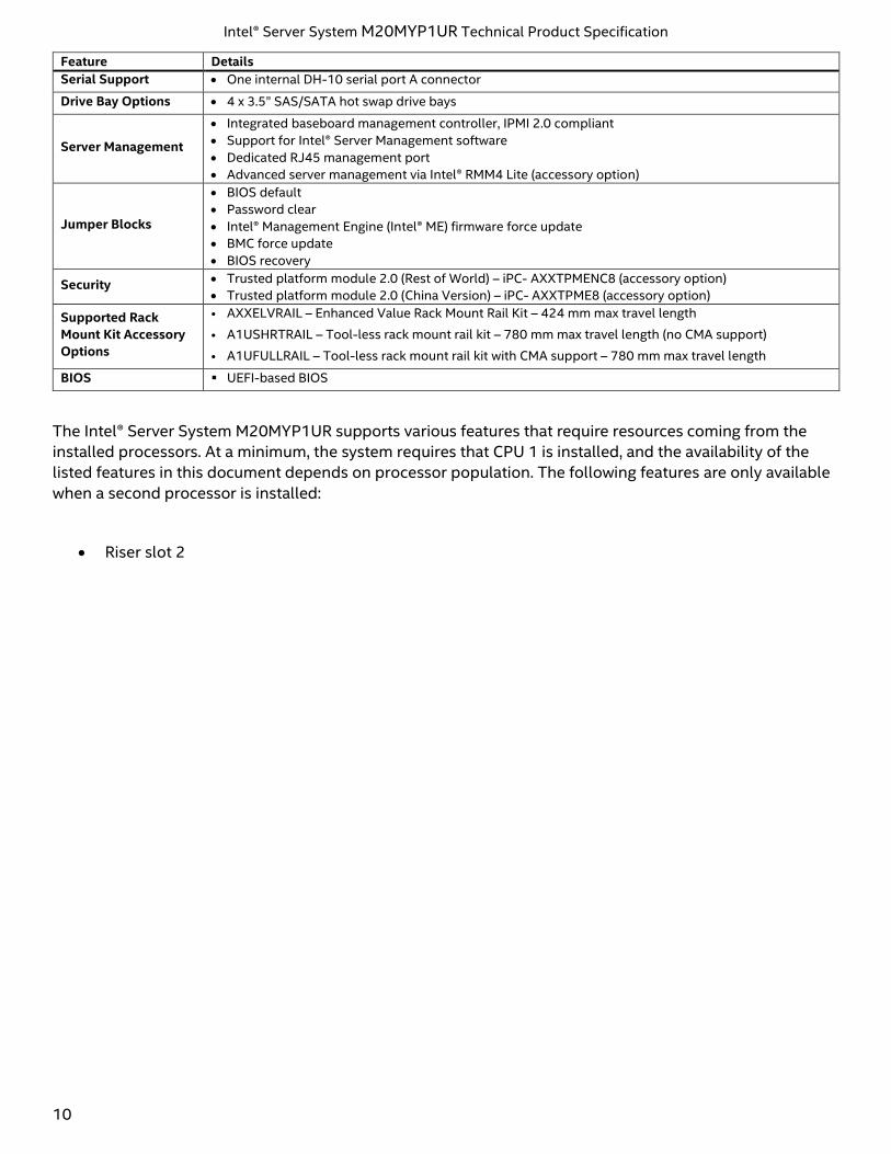
Feature Details
Serial Support • One internal DH-10 serial port A connector
Drive Bay Options • 4 x 3.5” SAS/SATA hot swap drive bays
Server Management
• Integrated baseboard management controller, IPMI 2.0 compliant
• Support for Intel® Server Management software
• Dedicated RJ45 management port
• Advanced server management via Intel® RMM4 Lite (accessory option)
Jumper Blocks
• BIOS default
• Password clear
• Intel® Management Engine (Intel® ME) firmware force update
• BMC force update
• BIOS recovery
Security • Trusted platform module 2.0 (Rest of World) – iPC- AXXTPMENC8 (accessory option)
• Trusted platform module 2.0 (China Version) – iPC- AXXTPME8 (accessory option)
Supported Rack
Mount Kit Accessory
Options
• AXXELVRAIL – Enhanced Value Rack Mount Rail Kit – 424 mm max travel length
• A1USHRTRAIL – Tool-less rack mount rail kit – 780 mm max travel length (no CMA support)
• A1UFULLRAIL – Tool-less rack mount rail kit with CMA support – 780 mm max travel length
BIOS ▪ UEFI-based BIOS
The Intel® Server System M20MYP1UR supports various features that require resources coming from the
installed processors. At a minimum, the system requires that CPU 1 is installed, and the availability of the
listed features in this document depends on processor population. The following features are only available
when a second processor is installed:
• Riser slot 2
Intel® Server System M20MYP1UR Technical Product Specification
11
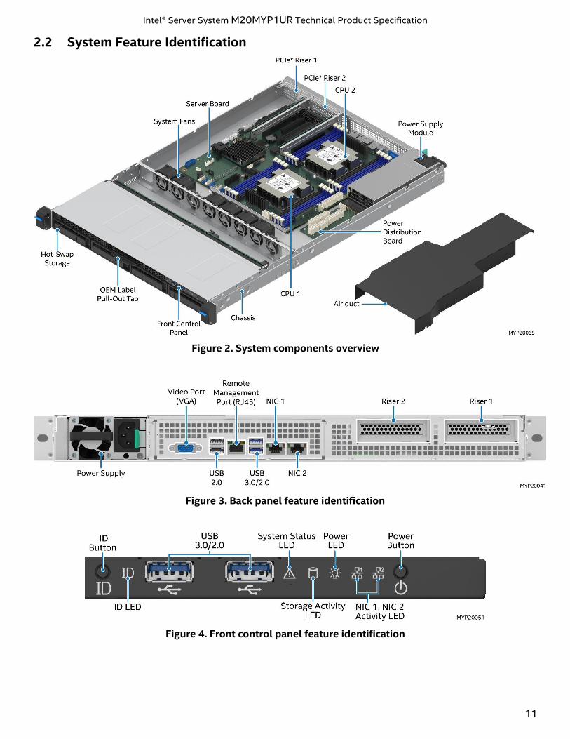
2.2 System Feature Identification
Figure 2. System components overview
Figure 3. Back panel feature identification
Figure 4. Front control panel feature identification
Intel® Server System M20MYP1UR Technical Product Specification
12
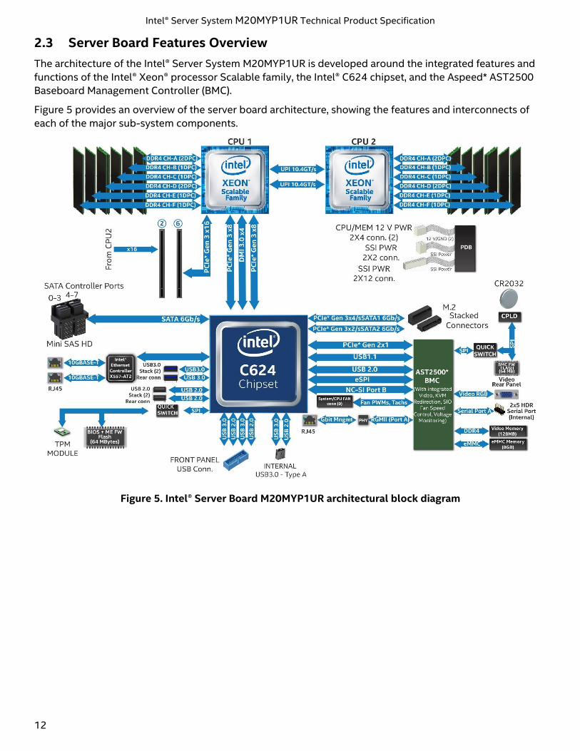
2.3 Server Board Features Overview
The architecture of the Intel® Server System M20MYP1UR is developed around the integrated features and
functions of the Intel® Xeon® processor Scalable family, the Intel® C624 chipset, and the Aspeed* AST2500
Baseboard Management Controller (BMC).
Figure 5 provides an overview of the server board architecture, showing the features and interconnects of
each of the major sub-system components.
Figure 5. Intel® Server Board M20MYP1UR architectural block diagram
Intel® Server System M20MYP1UR Technical Product Specification
13
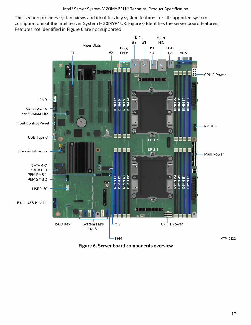
This section provides system views and identifies key system features for all supported system
configurations of the Intel Server System M20MYP1UR. Figure 6 Identifies the server board features.
Features not identified in Figure 6 are not supported.
Figure 6. Server board components overview
Intel® Server System M20MYP1UR Technical Product Specification
14
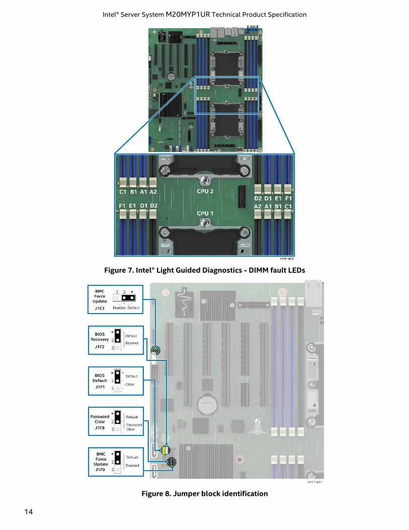
Figure 7. Intel® Light Guided Diagnostics - DIMM fault LEDs
Figure 8. Jumper block identification
Intel® Server System M20MYP1UR Technical Product Specification
15
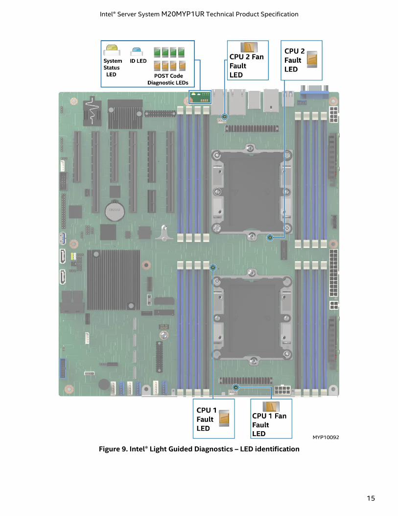
Figure 9. Intel® Light Guided Diagnostics – LED identification
Intel® Server System M20MYP1UR Technical Product Specification
16
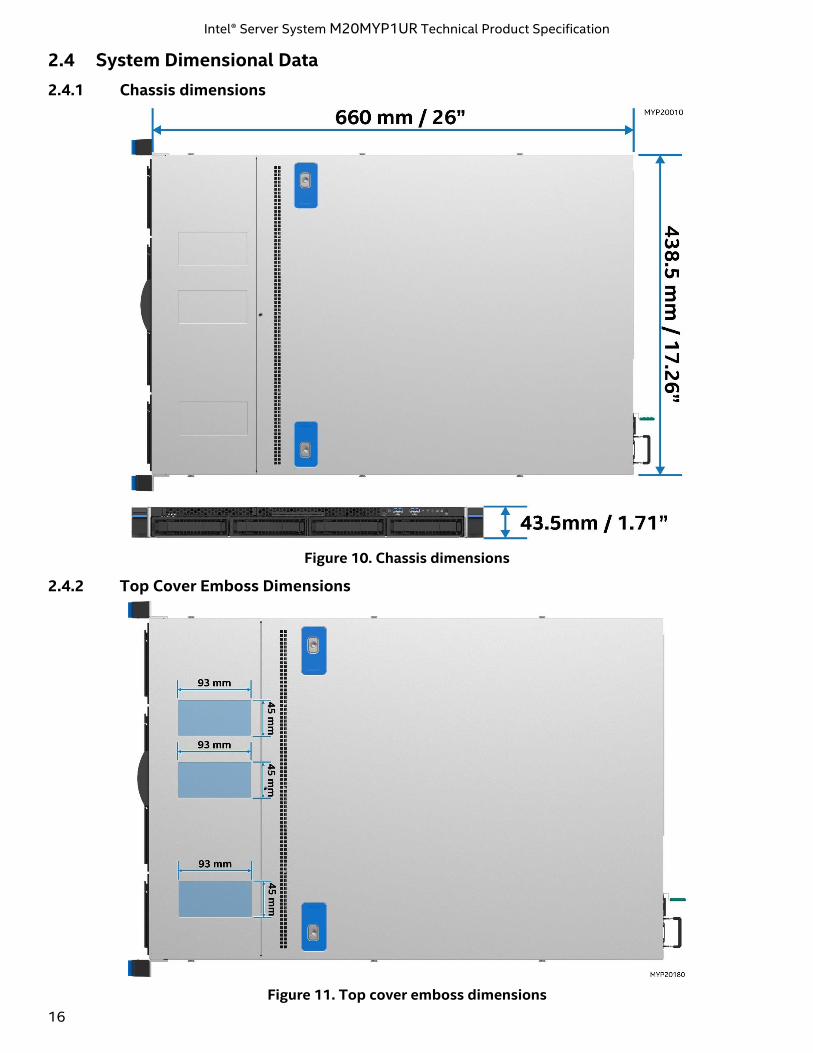
2.4 System Dimensional Data
2.4.1 Chassis dimensions
Figure 10. Chassis dimensions
2.4.2 Top Cover Emboss Dimensions
Figure 11. Top cover emboss dimensions
Intel® Server System M20MYP1UR Technical Product Specification
17
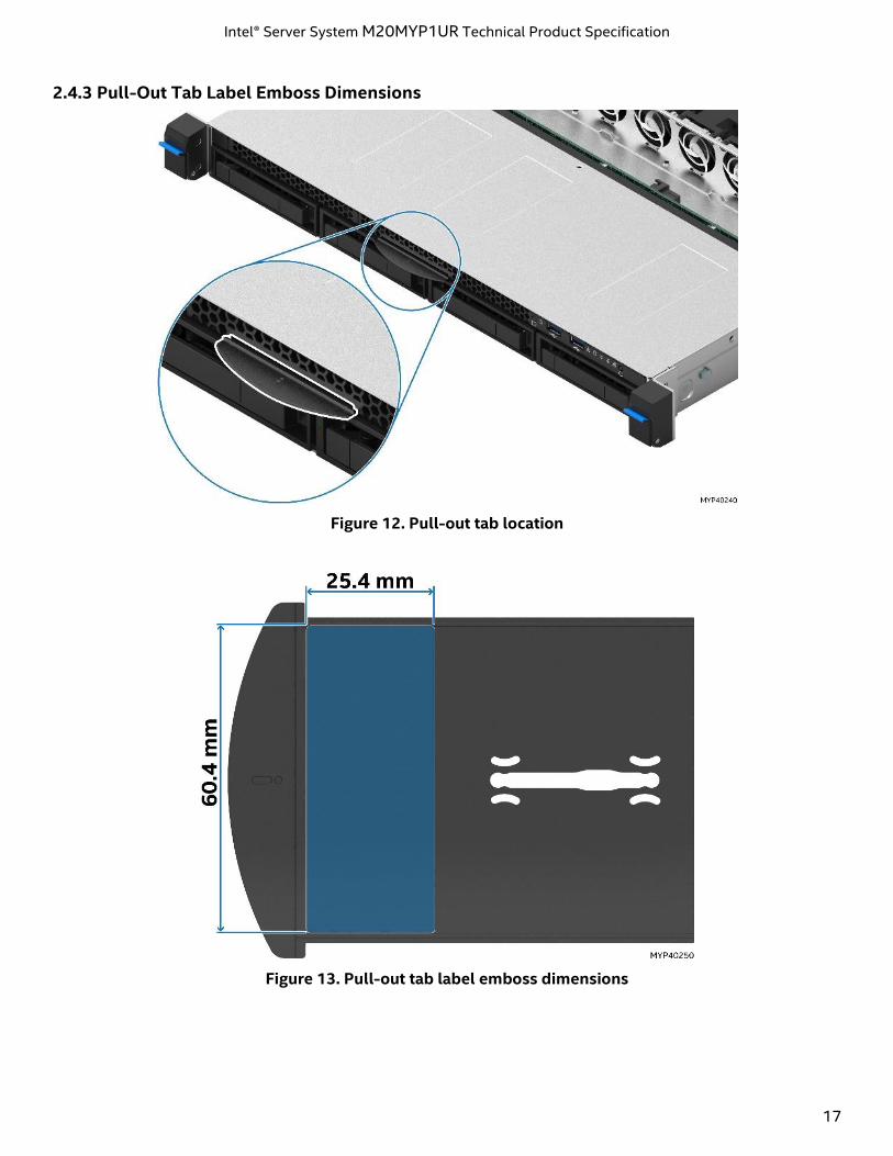
2.4.3 Pull-Out Tab Label Emboss Dimensions
Figure 12. Pull-out tab location
Figure 13. Pull-out tab label emboss dimensions
Intel® Server System M20MYP1UR Technical Product Specification
18
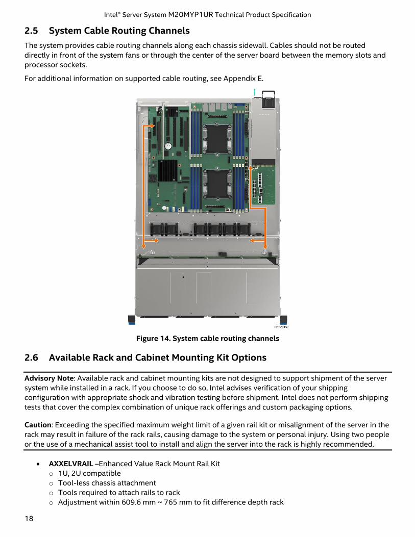
2.5 System Cable Routing Channels
The system provides cable routing channels along each chassis sidewall. Cables should not be routed
directly in front of the system fans or through the center of the server board between the memory slots and
processor sockets.
For additional information on supported cable routing, see Appendix E.
Figure 14. System cable routing channels
2.6 Available Rack and Cabinet Mounting Kit Options
Advisory Note: Available rack and cabinet mounting kits are not designed to support shipment of the server
system while installed in a rack. If you choose to do so, Intel advises verification of your shipping
configuration with appropriate shock and vibration testing before shipment. Intel does not perform shipping
tests that cover the complex combination of unique rack offerings and custom packaging options.
Caution: Exceeding the specified maximum weight limit of a given rail kit or misalignment of the server in the
rack may result in failure of the rack rails, causing damage to the system or personal injury. Using two people
or the use of a mechanical assist tool to install and align the server into the rack is highly recommended.
• AXXELVRAIL –Enhanced Value Rack Mount Rail Kit
o 1U, 2U compatible
o Tool-less chassis attachment
o Tools required to attach rails to rack
o Adjustment within 609.6 mm ~ 765 mm to fit difference depth rack
Intel® Server System M20MYP1UR Technical Product Specification
19
o 424.2 mm maximum travel length
o 130 lbs. (59 Kgs) max support weight
• A1USHRTRAIL – Premium Rail Kit with no cable management arm (CMA) support
o Tool-less installation
o Adjustment within 609.6 mm ~ 762 mm to fit difference depth rack
o 780 mm travel distance
o Tools required to attach rails to rack
o Full extension from rack
o 18 Kgs (39 lbs.) maximum supported weight
• A1UFULLRAIL – Premium Rail Kit with cable management arm (CMA) support
o Tool-less installation
o Adjustment within 609.6 mm ~ 762 mm to fit difference depth rack
o 780 mm travel distance
o Tools required to attach rails to rack
o Full extension from rack
o 18 Kgs (39 lbs.) maximum supported weight
o Compatible with Cable Management Arm AXX1U2UCMA
Intel® Server System M20MYP1UR Technical Product Specification
20
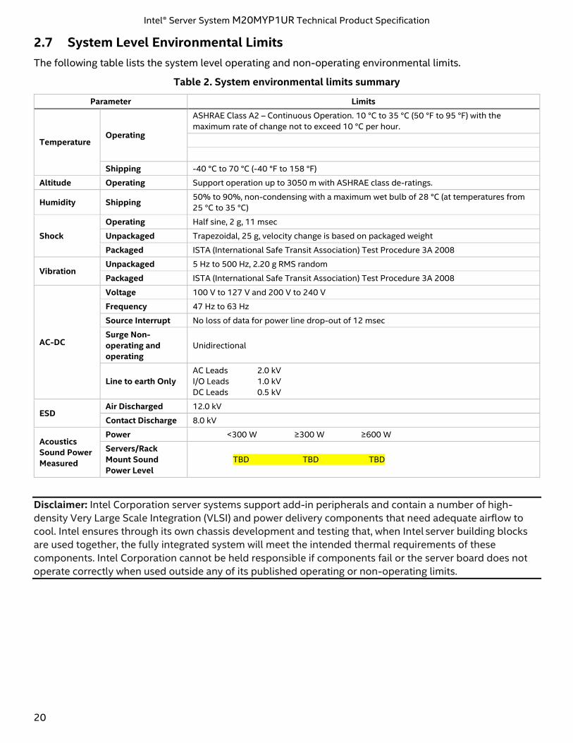
2.7 System Level Environmental Limits
The following table lists the system level operating and non-operating environmental limits.
Table 2. System environmental limits summary
Parameter Limits
Temperature Operating
ASHRAE Class A2 – Continuous Operation. 10 °C to 35 °C (50 °F to 95 °F) with the
maximum rate of change not to exceed 10 °C per hour.
Shipping -40 °C to 70 °C (-40 °F to 158 °F)
Altitude Operating Support operation up to 3050 m with ASHRAE class de-ratings.
Humidity Shipping 50% to 90%, non-condensing with a maximum wet bulb of 28 °C (at temperatures from
25 °C to 35 °C)
Shock
Operating Half sine, 2 g, 11 msec
Unpackaged Trapezoidal, 25 g, velocity change is based on packaged weight
Packaged ISTA (International Safe Transit Association) Test Procedure 3A 2008
Vibration Unpackaged 5 Hz to 500 Hz, 2.20 g RMS random
Packaged ISTA (International Safe Transit Association) Test Procedure 3A 2008
AC-DC
Voltage 100 V to 127 V and 200 V to 240 V
Frequency 47 Hz to 63 Hz
Source Interrupt No loss of data for power line drop-out of 12 msec
Surge Non-
operating and
operating
Unidirectional
Line to earth Only
AC Leads 2.0 kV
I/O Leads 1.0 kV
DC Leads 0.5 kV
ESD Air Discharged 12.0 kV
Contact Discharge 8.0 kV
Acoustics
Sound Power
Measured
Power <300 W ≥300 W ≥600 W
Servers/Rack
Mount Sound
Power Level
TBD TBD TBD
Disclaimer: Intel Corporation server systems support add-in peripherals and contain a number of high-
density Very Large Scale Integration (VLSI) and power delivery components that need adequate airflow to
cool. Intel ensures through its own chassis development and testing that, when Intel server building blocks
are used together, the fully integrated system will meet the intended thermal requirements of these
components. Intel Corporation cannot be held responsible if components fail or the server board does not
operate correctly when used outside any of its published operating or non-operating limits.
Intel® Server System M20MYP1UR Technical Product Specification
21
2.8 System Packaging
The original Intel packaging is designed to provide protection to a fully configured system and tested to
meet International Safe Transit Association (ISTA) Test Procedure 3A (2008). The packaging is also designed
to be re-used for shipment after system integration has been completed.
The original packaging includes two layers of boxes – an inner box and the outer shipping box – and various
protective inner packaging components. The boxes and packaging components are designed to function
together as a protective packaging system. When reused, all the original packaging material must be used,
including both boxes and each inner packaging component. In addition, all inner packaging components
must be reinstalled in the proper location to ensure adequate protection of the system for subsequent
shipment.
Note: The design of the inner packaging components does not prevent improper placement within the
packaging assembly. There is only one correct packaging assembly that allows the package to meet the ISTA
Test Procedure 3A (2008) limits. For complete packaging assembly instructions, see the Intel® Server System
M20MYP1UR System Integration and Service Guide.
Failure to follow the specified packaging assembly instructions may result in damage to the system during
shipment.
• Outer shipping box external dimensions
o Length: 994 mm
o Width: 592 mm
o Height: 260 mm
• Inner box internal dimension
o Length: 980 mm
o Width: 578 mm
o Height: 232 mm
Intel® Server System M20MYP1UR Technical Product Specification
22
3. Processor Support
The Intel® Server System M20MYP1UR includes two LGA3647-0 processor sockets supporting the 1st and 2nd
Gen Intel® Xeon® processor Scalable family (Gold, Silver, and Bronze) with a maximum Thermal Design Power
(TDP) of up to 150 W in dual processor configurations and up to 165 W in select single processor
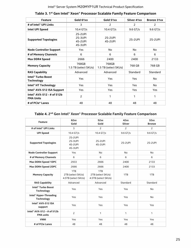
configurations. Table 3 and Table 4 list an overview of the different processor series features.
Note: Previous generations Intel® Xeon® processors are not compatible with this server system.
Visit http://www.intel.com/support for a complete list of supported processors.
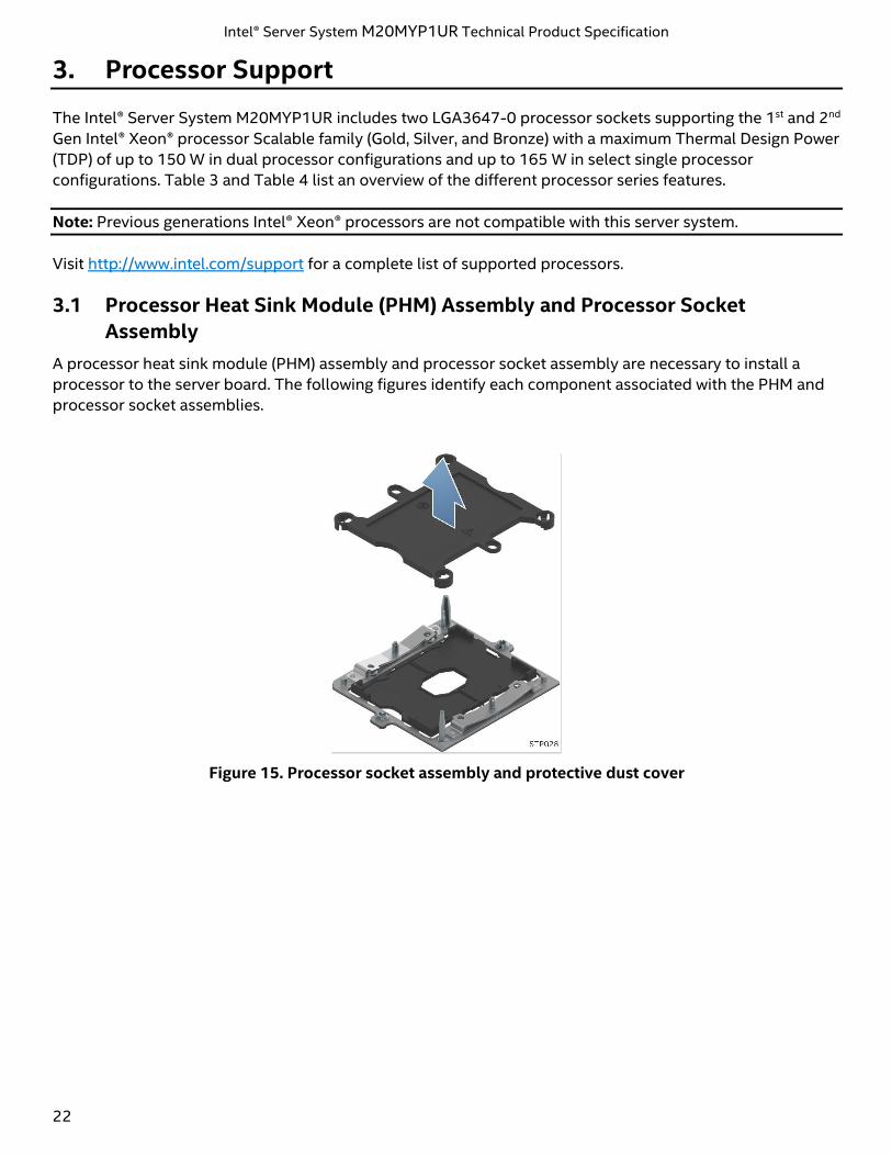
3.1 Processor Heat Sink Module (PHM) Assembly and Processor Socket
Assembly
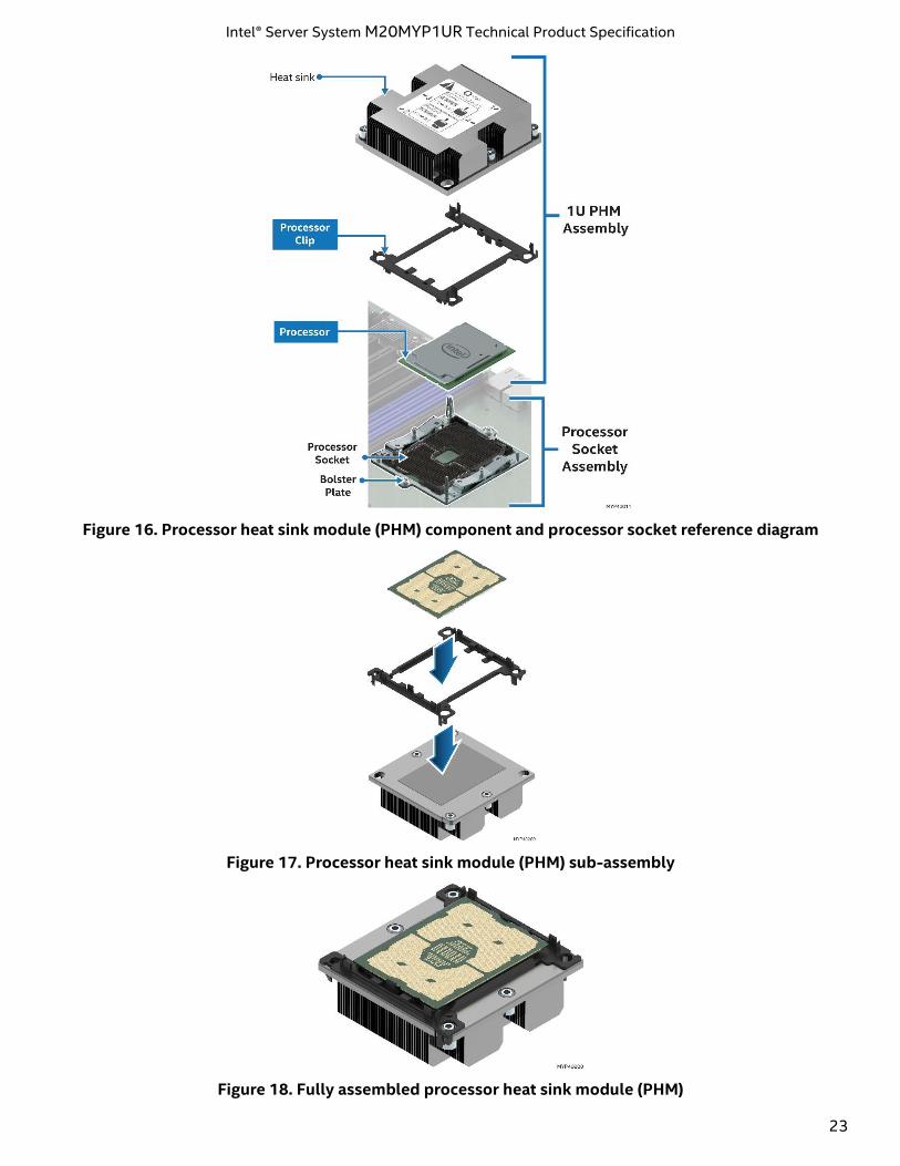
A processor heat sink module (PHM) assembly and processor socket assembly are necessary to install a
processor to the server board. The following figures identify each component associated with the PHM and
processor socket assemblies.
Figure 15. Processor socket assembly and protective dust cover
Intel® Server System M20MYP1UR Technical Product Specification
23
Figure 16. Processor heat sink module (PHM) component and processor socket reference diagram
Figure 17. Processor heat sink module (PHM) sub-assembly
Figure 18. Fully assembled processor heat sink module (PHM)
Intel® Server System M20MYP1UR Technical Product Specification
24
3.2 Processor Thermal Design Power (TDP) Support
To allow for optimal operation and provide for best long-term reliability of Intel processor-based systems,
the processor must remain within the defined minimum and maximum case temperature (TCASE)
specifications. Thermal solutions not designed to provide sufficient thermal capability may affect the long-
term reliability of the processor and system.
The server system described in this document is designed to support the Intel® Xeon® processor Scalable
family TDP guidelines up to and including 150 W in dual processor configurations, and up to 165 W in select
single processor configurations.
Disclaimer Note: Intel® Server Systems contain a number of high-density very large scale integration (VLSI)
and power delivery components that need adequate airflow to cool. Intel ensures, through its own chassis
development and testing, that when Intel server building blocks are used together, the fully integrated
system meets the intended thermal requirements of these components. It is the responsibility of system
integrators who choose not to use Intel developed server building blocks to consult vendor datasheets and
operating parameters to determine the amount of airflow required for their specific applications and
environmental conditions. Intel Corporation cannot be held responsible if components fail or the server
board does not operate correctly when used outside any of its published operating or non-operating limits.
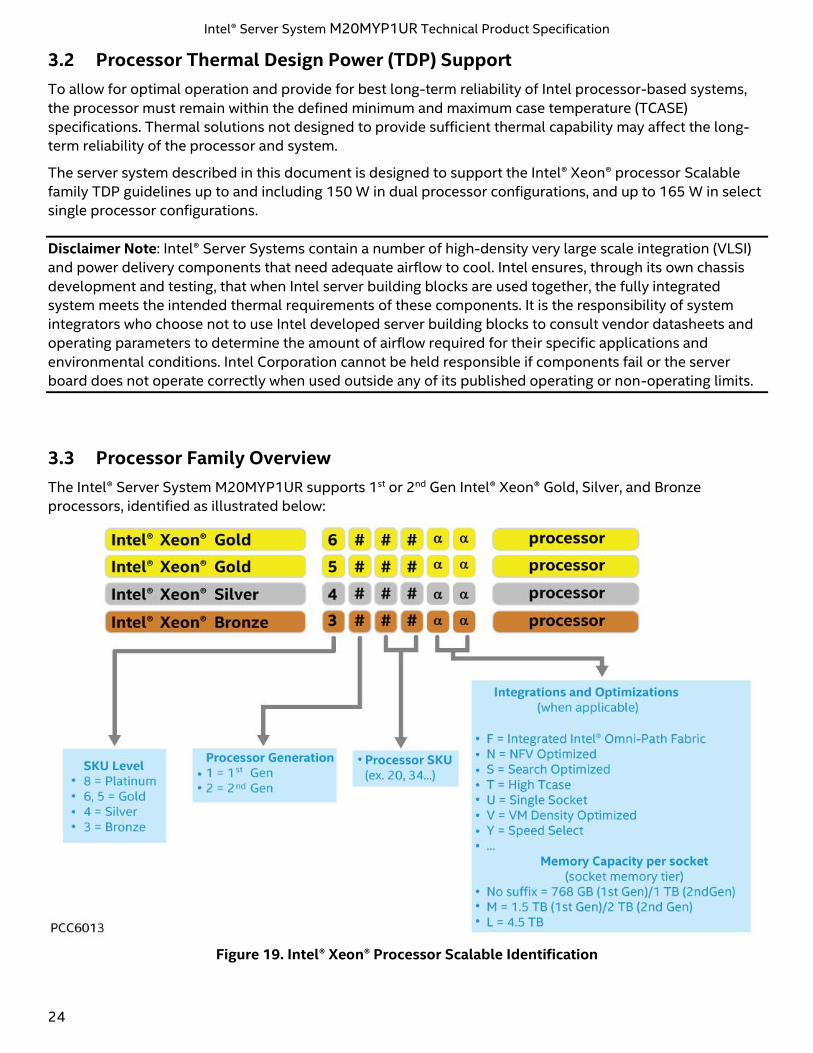
3.3 Processor Family Overview
The Intel® Server System M20MYP1UR supports 1st or 2nd Gen Intel® Xeon® Gold, Silver, and Bronze
processors, identified as illustrated below:
Figure 19. Intel® Xeon® Processor Scalable Identification
Intel® Server System M20MYP1UR Technical Product Specification
25
Table 3. 1st Gen Intel® Xeon® Processor Scalable Family Feature Comparison
Feature Gold 61xx Gold 51xx Silver 41xx Bronze 31xx
# of Intel® UPI Links 3 2 2 2
Intel UPI Speed 10.4 GT/s 10.4 GT/s 9.6 GT/s 9.6 GT/s
Supported Topologies
2S-2UPI
2S-3UPI
4S-2UPI
4S-3UPI
2S-2UPI
4S-2UPI 2S-2UPI 2S-2UPI
Node Controller Support Yes No No No
# of Memory Channels 6 6 6 6
Max DDR4 Speed 2666 2400 2400 2133
Memory Capacity 768GB
1.5 TB (select SKUs)
768GB
1.5 TB (select SKUs) 768 GB 768 GB
RAS Capability Advanced Advanced Standard Standard
Intel® Turbo Boost
Technology Yes Yes Yes No
Intel® HT Technology Yes Yes Yes No
Intel® AVX-512 ISA Support Yes Yes Yes Yes
Intel® AVX-512 - # of 512b
FMA Units 2 1 1 1
# of PCIe* Lanes 48 48 48 48
Table 4. 2nd Gen Intel® Xeon® Processor Scalable Family Feature Comparison
Feature 62xx
Gold
52xx
Gold
42xx
Silver
32xx
Bronze
# of Intel® UPI Links 3 2 2 2
UPI Speed 10.4 GT/s 10.4 GT/s 9.6 GT/s 9.6 GT/s
Supported Topologies
2S-2UPI
2S-3UPI
4S-2UPI
4S-3UPI
2S-2UPI
4S-2UPI 2S-2UPI 2S-2UPI
Node Controller Support Yes No No No
# of Memory Channels 6 6 6 6
Max DDR4 Speed 1DPC 2933 2666 2400 2133
Max DDR4 Speed 2DPC 2666 2666 2400 2133
Memory Capacity
1TB
2TB (select SKUs)
4.5TB (select SKUs)
1TB
2TB (select SKUs)
4.5TB (select SKUs)
1TB 1TB
RAS Capability Advanced Advanced Standard Standard
Intel® Turbo Boost
Technology Yes Yes Yes No
Intel® Hyper-Threading
Technology Yes Yes Yes No
Intel® AVX-512 ISA
support Yes Yes Yes Yes
Intel® AVX-512 – # of 512b
FMA units 2 1 1 1
VNNI Yes Yes Yes Yes
# of PCIe Lanes 48 48 48 48
Intel® Server System M20MYP1UR Technical Product Specification
26
3.3.1 Supported Technologies
The 1st and 2nd Gen Intel® Xeon® processor Scalable families combine several key system components into a
single processor package, including the CPU cores, Integrated Memory Controller (IMC), and Integrated IO
Module (IIO). The processor includes many core and uncore features and technologies described in the
following sections.
Core features:
• Intel® Ultra Path Interconnect (Intel® UPI) – up to 10.4 GT/s
• Intel® Speed Shift Technology
• Intel® 64 architecture
• Enhanced Intel SpeedStep® Technology
• Intel® Turbo Boost Technology 2.0
• Intel® Hyper-Threading Technology (Intel® HT Technology)
• Intel® Virtualization Technology for IA-32, Intel® 64 and Intel® Architecture (Intel® VT-x)
• Intel® Virtualization Technology for Directed I/O (Intel® VT-d)
• Execute Disable Bit
• Intel® Trusted Execution Technology (Intel® TXT)
• Intel® Advanced Vector Extensions 512 (Intel® AVX-512)
• Intel® Advanced Encryption Standard New Instructions (Intel® AES-NI)
Additional Core Features on 2nd Gen Intel® Xeon®:
• Intel® Deep Learning Boost through VNNI
• Intel® Speed Select Technology (select SKUs)
• Intel® Resource Director Technology
Uncore features:
• Up to 48 PCIe* 3.0 lanes per CPU – 79 GB/s bi-directional pipeline
• 6 DDR4 memory channels supported per CPU
• DMI3/PCIe 3.0 interface with a peak transfer rate of 8.0 GT/s.
• Non-Transparent Bridge (NTB) enhancements – three full duplex NTBs and 32 MSI-X vectors
• Intel® Volume Management Device (Intel® VMD) – manages CPU attached NVM Express* (NVMe*) solid
state drives (SSDs)
• Intel® Quick Data Technology
• Support for Intel® Node Manager 4.0
3.4 Processor Population Rules
Note: The server board may support dual-processor configurations consisting of different processors that
meet the following defined criteria. Figure 5 provides an architecture block diagram. However, Intel does not
perform validation testing of this configuration. In addition, Intel does not ensure that a server system
configured with unmatched processors will operate reliably. The system BIOS attempts to operate with
processors that are not matched but are generally compatible. For optimal system performance in dual-
processor configurations, Intel recommends that identical processors be installed.
When using a single processor configuration, the processor must be installed into the processor socket
labeled “CPU_1”.
Note: Some server board features may not be functional unless a second processor is installed.
Intel® Server System M20MYP1UR Technical Product Specification
27
When two processors are installed, the following population rules apply:
• Both processors must have identical model numbers.
• Both processors must have the same number of cores.
• Both processors must have the same cache sizes for all levels of processor cache memory.
• Both processors must support identical DDR4 memory frequencies.
Population rules are applicable to any combination of processors within the Intel Xeon processor Scalable
family.
Processors with different core frequencies can be mixed in a system if the prior conditions are met. If this
condition is detected, all processor core frequencies are set to the lowest common denominator (highest
common speed) and an error is reported.
Processor stepping within a common processor family can be mixed if it is listed in the processor
specification updates published by Intel. Mixing of stepping is only validated and supported between
processors that are plus or minus one stepping from each other.
For additional information on processor population rules, refer to the Intel® Server System BIOS EPS for Intel®
Xeon® processor Scalable Family.
3.5 Processor Initialization Error Summary
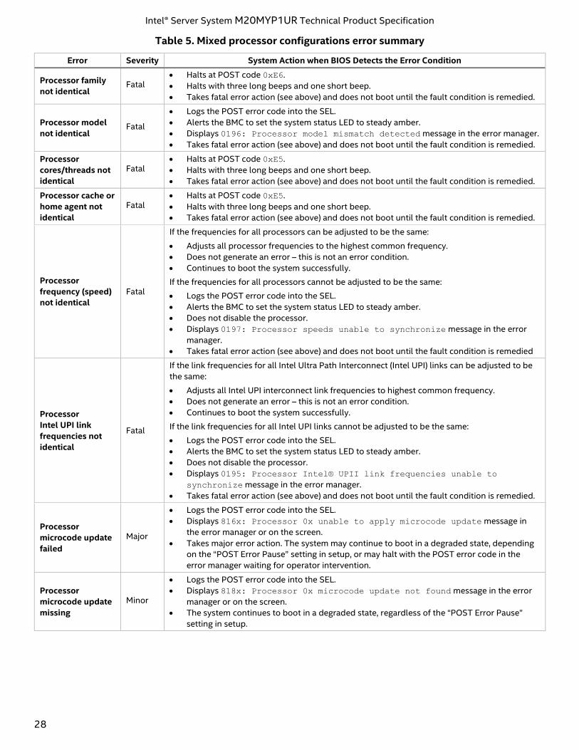
Table 5 describes mixed processor conditions and actions for all Intel server boards and Intel server systems
designed around the Intel Xeon processor Scalable family and Intel C620 series chipset architecture. The
errors fall into one of the following categories:
• Fatal: If the system cannot boot, POST halts and delivers the following error message to the BIOS
Setup Error Manager screen:
Unrecoverable fatal error found. System will not boot until the error is
resolved
Press <F2> to enter setup
When the <F2> key on the keyboard is pressed, the error message is displayed on the BIOS Setup
Error Manager screen and an error is logged to the system event log (SEL) with the POST error code.
The “POST Error Pause” option setting in the BIOS setup does not have any effect on this error.
If the system is not able to boot, the system generates a beep code consisting of three long beeps
and one short beep. The system cannot boot unless the error is resolved. The faulty component must
be replaced.
The system status LED is set to a steady amber color for all fatal errors that are detected during
processor initialization. A steady amber system status LED indicates that an unrecoverable system
failure condition has occurred.
• Major: An error message is displayed to the error manager screen and an error is logged to the SEL. If
the BIOS setup option “Post Error Pause” is enabled, operator intervention is required to continue
booting the system. If the BIOS setup option “POST Error Pause” is disabled, the system continues to
boot.
• Minor: An error message may display to the screen or to the BIOS setup error manager and the POST
error code is logged to the SEL. The system continues booting in a degraded state. The user may want
to replace the erroneous unit. The “POST Error Pause” option setting in the BIOS setup does not have
any effect on this error.
Intel® Server System M20MYP1UR Technical Product Specification
28
Table 5. Mixed processor configurations error summary
Error Severity System Action when BIOS Detects the Error Condition
Processor family
not identical Fatal
• Halts at POST code 0xE6.
• Halts with three long beeps and one short beep.
• Takes fatal error action (see above) and does not boot until the fault condition is remedied.
Processor model
not identical Fatal
• Logs the POST error code into the SEL.
• Alerts the BMC to set the system status LED to steady amber.
• Displays 0196: Processor model mismatch detected message in the error manager.
• Takes fatal error action (see above) and does not boot until the fault condition is remedied.
Processor
cores/threads not
identical
Fatal • Halts at POST code 0xE5.
• Halts with three long beeps and one short beep.
• Takes fatal error action (see above) and does not boot until the fault condition is remedied.
Processor cache or
home agent not
identical
Fatal • Halts at POST code 0xE5.
• Halts with three long beeps and one short beep.
• Takes fatal error action (see above) and does not boot until the fault condition is remedied.
Processor
frequency (speed)
not identical
Fatal
If the frequencies for all processors can be adjusted to be the same:
• Adjusts all processor frequencies to the highest common frequency.
• Does not generate an error – this is not an error condition.
• Continues to boot the system successfully.
If the frequencies for all processors cannot be adjusted to be the same:
• Logs the POST error code into the SEL.
• Alerts the BMC to set the system status LED to steady amber.
• Does not disable the processor.
• Displays 0197: Processor speeds unable to synchronize message in the error
manager.
• Takes fatal error action (see above) and does not boot until the fault condition is remedied
Processor
Intel UPI link
frequencies not
identical
Fatal
If the link frequencies for all Intel Ultra Path Interconnect (Intel UPI) links can be adjusted to be
the same:
• Adjusts all Intel UPI interconnect link frequencies to highest common frequency.
• Does not generate an error – this is not an error condition.
• Continues to boot the system successfully.
If the link frequencies for all Intel UPI links cannot be adjusted to be the same:
• Logs the POST error code into the SEL.
• Alerts the BMC to set the system status LED to steady amber.
• Does not disable the processor.
• Displays 0195: Processor Intel® UPII link frequencies unable to
synchronize message in the error manager.
• Takes fatal error action (see above) and does not boot until the fault condition is remedied.
Processor
microcode update
failed
Major
• Logs the POST error code into the SEL.
• Displays 816x: Processor 0x unable to apply microcode update message in
the error manager or on the screen.
• Takes major error action. The system may continue to boot in a degraded state, depending
on the “POST Error Pause” setting in setup, or may halt with the POST error code in the
error manager waiting for operator intervention.
Processor
microcode update
missing
Minor
• Logs the POST error code into the SEL.
• Displays 818x: Processor 0x microcode update not found message in the error
manager or on the screen.
• The system continues to boot in a degraded state, regardless of the “POST Error Pause”
setting in setup.
Intel® Server System M20MYP1UR Technical Product Specification
29
4. Memory Support
This chapter describes the architecture that drives the memory sub-system, supported memory types,
memory population rules, and supported memory reliability, availability, and serviceability (RAS) features.
4.1 Memory Subsystem Architecture
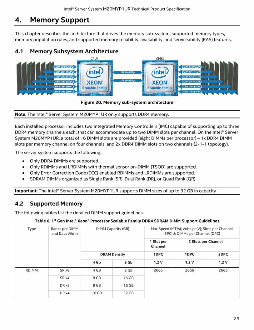
Figure 20. Memory sub-system architecture
Note: The Intel® Server System M20MYP1UR only supports DDR4 memory.
Each installed processor includes two Integrated Memory Controllers (IMC) capable of supporting up to three
DDR4 memory channels each, that can accommodate up to two DIMM slots per channel. On the Intel® Server
System M20MYP1UR, a total of 16 DIMM slots are provided (eight DIMMs per processor) – 1x DDR4 DIMM
slots per memory channel on four channels, and 2x DDR4 DIMM slots on two channels (2-1-1 topology).
The server system supports the following:
• Only DDR4 DIMMs are supported.
• Only RDIMMs and LRDIMMs with thermal sensor on-DIMM (TSOD) are supported.
• Only Error Correction Code (ECC) enabled RDIMMs and LRDIMMs are supported.
• SDRAM DIMMs organized as Single Rank (SR), Dual Rank (DR), or Quad Rank (QR)
Important: The Intel® Server System M20MYP1UR supports DIMM sizes of up to 32 GB in capacity
4.2 Supported Memory
The following tables list the detailed DIMM support guidelines:
Table 6. 1st Gen Intel® Xeon® Processor Scalable Family DDR4 SDRAM DIMM Support Guidelines
Type Ranks per DIMM
and Data Width
DIMM Capacity (GB) Max Speed (MT/s); Voltage (V); Slots per Channel
(SPC) & DIMMs per Channel (DPC)
1 Slot per
Channel
2 Slots per Channel
DRAM Density 1DPC 1DPC 2DPC
4 Gb 8 Gb 1.2 V 1.2 V 1.2 V
RDIMM SR x8 4 GB 8 GB 2666 2666 2666
SR x4 8 GB 16 GB
DR x8 8 GB 16 GB
DR x4 16 GB 32 GB
Intel® Server System M20MYP1UR Technical Product Specification
30
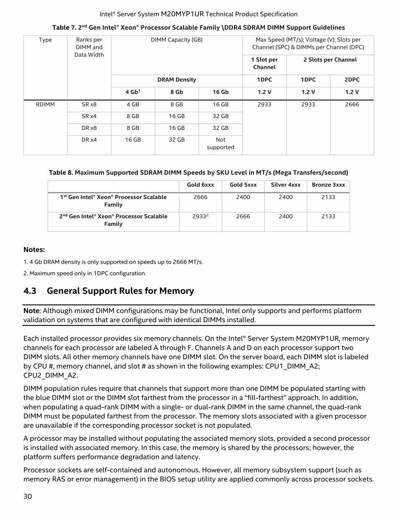
Table 7. 2nd Gen Intel® Xeon® Processor Scalable Family \DDR4 SDRAM DIMM Support Guidelines
Type Ranks per
DIMM and
Data Width
DIMM Capacity (GB) Max Speed (MT/s); Voltage (V); Slots per
Channel (SPC) & DIMMs per Channel (DPC)
1 Slot per
Channel
2 Slots per Channel
DRAM Density 1DPC 1DPC 2DPC
4 Gb1 8 Gb 16 Gb 1.2 V 1.2 V 1.2 V
RDIMM SR x8 4 GB 8 GB 16 GB 2933 2933 2666
SR x4 8 GB 16 GB 32 GB
DR x8 8 GB 16 GB 32 GB
DR x4 16 GB 32 GB Not
supported
Table 8. Maximum Supported SDRAM DIMM Speeds by SKU Level in MT/s (Mega Transfers/second)
Gold 6xxx Gold 5xxx Silver 4xxx Bronze 3xxx
1st Gen Intel® Xeon® Processor Scalable
Family
2666 2400 2400 2133
2nd Gen Intel® Xeon® Processor Scalable
Family
29332 2666 2400 2133
Notes:
1. 4 Gb DRAM density is only supported on speeds up to 2666 MT/s.
2. Maximum speed only in 1DPC configuration.
4.3 General Support Rules for Memory
Note: Although mixed DIMM configurations may be functional, Intel only supports and performs platform
validation on systems that are configured with identical DIMMs installed.
Each installed processor provides six memory channels. On the Intel® Server System M20MYP1UR, memory
channels for each processor are labeled A through F. Channels A and D on each processor support two
DIMM slots. All other memory channels have one DIMM slot. On the server board, each DIMM slot is labeled
by CPU #, memory channel, and slot # as shown in the following examples: CPU1_DIMM_A2;
CPU2_DIMM_A2.
DIMM population rules require that channels that support more than one DIMM be populated starting with
the blue DIMM slot or the DIMM slot farthest from the processor in a “fill-farthest” approach. In addition,
when populating a quad-rank DIMM with a single- or dual-rank DIMM in the same channel, the quad-rank
DIMM must be populated farthest from the processor. The memory slots associated with a given processor
are unavailable if the corresponding processor socket is not populated.
A processor may be installed without populating the associated memory slots, provided a second processor
is installed with associated memory. In this case, the memory is shared by the processors; however, the
platform suffers performance degradation and latency.
Processor sockets are self-contained and autonomous. However, all memory subsystem support (such as
memory RAS or error management) in the BIOS setup utility are applied commonly across processor sockets.
Intel® Server System M20MYP1UR Technical Product Specification
31
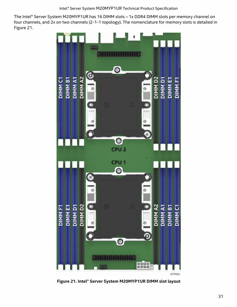
The Intel® Server System M20MYP1UR has 16 DIMM slots – 1x DDR4 DIMM slots per memory channel on
four channels, and 2x on two channels (2-1-1 topology). The nomenclature for memory slots is detailed in
Figure 21.
Figure 21. Intel® Server System M20MYP1UR DIMM slot layout
Intel® Server System M20MYP1UR Technical Product Specification
32
The DIMM population requirements are listed below.
• For multiple DIMMs per channel:
o For RDIMM, LRDIMM, 3DS RDIMM, or 3DS LRDIMM, always populate DIMMs with higher electrical
loading in the first slot of a channel (blue slot) followed by the second slot.
• When only one DIMM is used in the channels A or D, it must be populated in the BLUE DIMM slot.
o A maximum of 8 logical ranks can be used on any one channel, as well as a maximum of 10
physical ranks loaded on a channel.
• Mixing of DDR4 DIMM Types (RDIMM, LRDIMM, 3DS-RDIMM, 3DS-LRDIMM, NVDIMM) within channel
or socket or across sockets is not supported. This is a Fatal Error Halt in Memory Initialization.
• Mixing DIMMs of different frequencies and latencies is not supported within or across processor
sockets. If a mixed configuration is encountered, the BIOS attempts to operate at the highest
common frequency and the lowest latency possible.
• LRDIMM Rank Multiplication Mode and Direct Map Mode must not be mixed within or across
processor sockets. This is a Fatal Error Halt in Memory Initialization.
See Section 6.1.1 for thermal requirements for memory population.
4.3.1 DIMM Population Guidelines for Best Performance
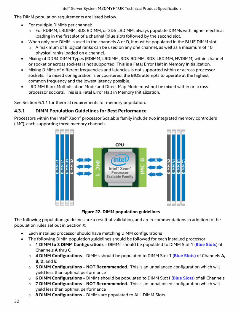
Processors within the Intel® Xeon® processor Scalable family include two integrated memory controllers
(IMC), each supporting three memory channels.
Figure 22. DIMM population guidelines
The following population guidelines are a result of validation, and are recommendations in addition to the
population rules set out in Section X:
• Each installed processor should have matching DIMM configurations
• The following DIMM population guidelines should be followed for each installed processor
o 1 DIMM to 3 DIMM Configurations – DIMMs should be populated to DIMM Slot 1 (Blue Slots) of
Channels A thru C
o 4 DIMM Configurations – DIMMs should be populated to DIMM Slot 1 (Blue Slots) of Channels A,
B, D, and E
o 5 DIMM Configurations – NOT Recommended. This is an unbalanced configuration which will
yield less than optimal performance
o 6 DIMM Configurations – DIMMs should be populated to DIMM Slot1 (Blue Slots) of all Channels
o 7 DIMM Configurations – NOT Recommended. This is an unbalanced configuration which will
yield less than optimal performance
o 8 DIMM Configurations – DIMMs are populated to ALL DIMM Slots
Intel® Server System M20MYP1UR Technical Product Specification
33
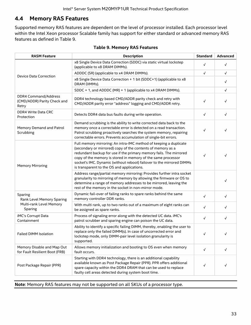
4.4 Memory RAS Features
Supported memory RAS features are dependent on the level of processor installed. Each processor level
within the Intel Xeon processor Scalable family has support for either standard or advanced memory RAS
features as defined in Table 9.
Table 9. Memory RAS Features
RASM Feature Description Standard Advanced
Device Data Correction
x8 Single Device Data Correction (SDDC) via static virtual lockstep
(applicable to x8 DRAM DIMMs). √ √
ADDDC (SR) (applicable to x4 DRAM DIMMs). √ √
x8 Single Device Data Correction + 1 bit (SDDC+1) (applicable to x8
DRAM DIMMs). √
SDDC + 1, and ADDDC (MR) + 1 (applicable to x4 DRAM DIMMs). √
DDR4 Command/Address
(CMD/ADDR) Parity Check and
Retry
DDR4 technology based CMD/ADDR parity check and retry with
CMD/ADDR parity error “address” logging and CMD/ADDR retry. √ √
DDR4 Write Data CRC
Protection Detects DDR4 data bus faults during write operation. √ √
Memory Demand and Patrol
Scrubbing
Demand scrubbing is the ability to write corrected data back to the
memory once a correctable error is detected on a read transaction.
Patrol scrubbing proactively searches the system memory, repairing
correctable errors. Prevents accumulation of single-bit errors.
√ √
Memory Mirroring
Full memory mirroring: An intra-IMC method of keeping a duplicate
(secondary or mirrored) copy of the contents of memory as a
redundant backup for use if the primary memory fails. The mirrored
copy of the memory is stored in memory of the same processor
socket's IMC. Dynamic (without reboot) failover to the mirrored DIMMs
is transparent to the OS and applications.
√ √
Address range/partial memory mirroring: Provides further intra socket
granularity to mirroring of memory by allowing the firmware or OS to
determine a range of memory addresses to be mirrored, leaving the
rest of the memory in the socket in non-mirror mode.
√
Sparing
Rank Level Memory Sparing
Multi-rank Level Memory
Sparing
Dynamic fail-over of failing ranks to spare ranks behind the same
memory controller DDR ranks. √ √
With multi rank, up to two ranks out of a maximum of eight ranks can
be assigned as spare ranks. √ √
iMC’s Corrupt Data
Containment
Process of signaling error along with the detected UC data. iMC's
patrol scrubber and sparing engine can poison the UC data. √ √
Failed DIMM Isolation
Ability to identify a specific failing DIMM, thereby, enabling the user to
replace only the failed DIMM(s). In case of uncorrected error and
lockstep mode, only DIMM-pair level isolation granularity is
supported.
√ √
Memory Disable and Map Out
for Fault Resilient Boot (FRB)
Allows memory initialization and booting to OS even when memory
fault occurs. √ √
Post Package Repair (PPR)
Starting with DDR4 technology, there is an additional capability
available known as Post Package Repair (PPR). PPR offers additional
spare capacity within the DDR4 DRAM that can be used to replace
faulty cell areas detected during system boot time.
√ √
Note: Memory RAS features may not be supported on all SKUs of a processor type.
Intel® Server System M20MYP1UR Technical Product Specification
34
4.4.1 DIMM Population Rules and BIOS Setup for Memory RAS
The following rules apply when enabling RAS features:
• Memory sparing and memory mirroring options are enabled in BIOS setup. Memory sparing and
memory mirroring options are mutually exclusive; only one operating mode may be selected in BIOS
setup.
• If a RAS mode has been enabled and the memory configuration is not able to support it during boot,
the system falls back to independent channel mode and log and display errors.
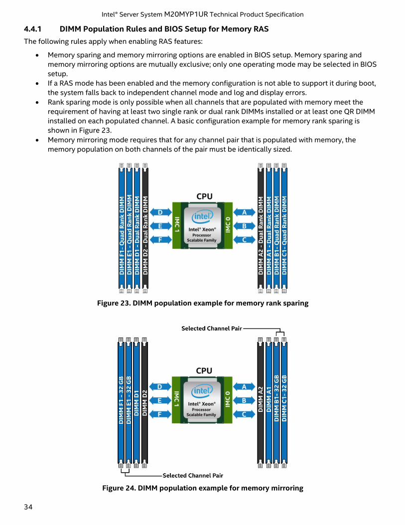
• Rank sparing mode is only possible when all channels that are populated with memory meet the
requirement of having at least two single rank or dual rank DIMMs installed or at least one QR DIMM
installed on each populated channel. A basic configuration example for memory rank sparing is
shown in Figure 23.
• Memory mirroring mode requires that for any channel pair that is populated with memory, the
memory population on both channels of the pair must be identically sized.
Figure 23. DIMM population example for memory rank sparing
Figure 24. DIMM population example for memory mirroring
Intel® Server System M20MYP1UR Technical Product Specification
35
5. System Power
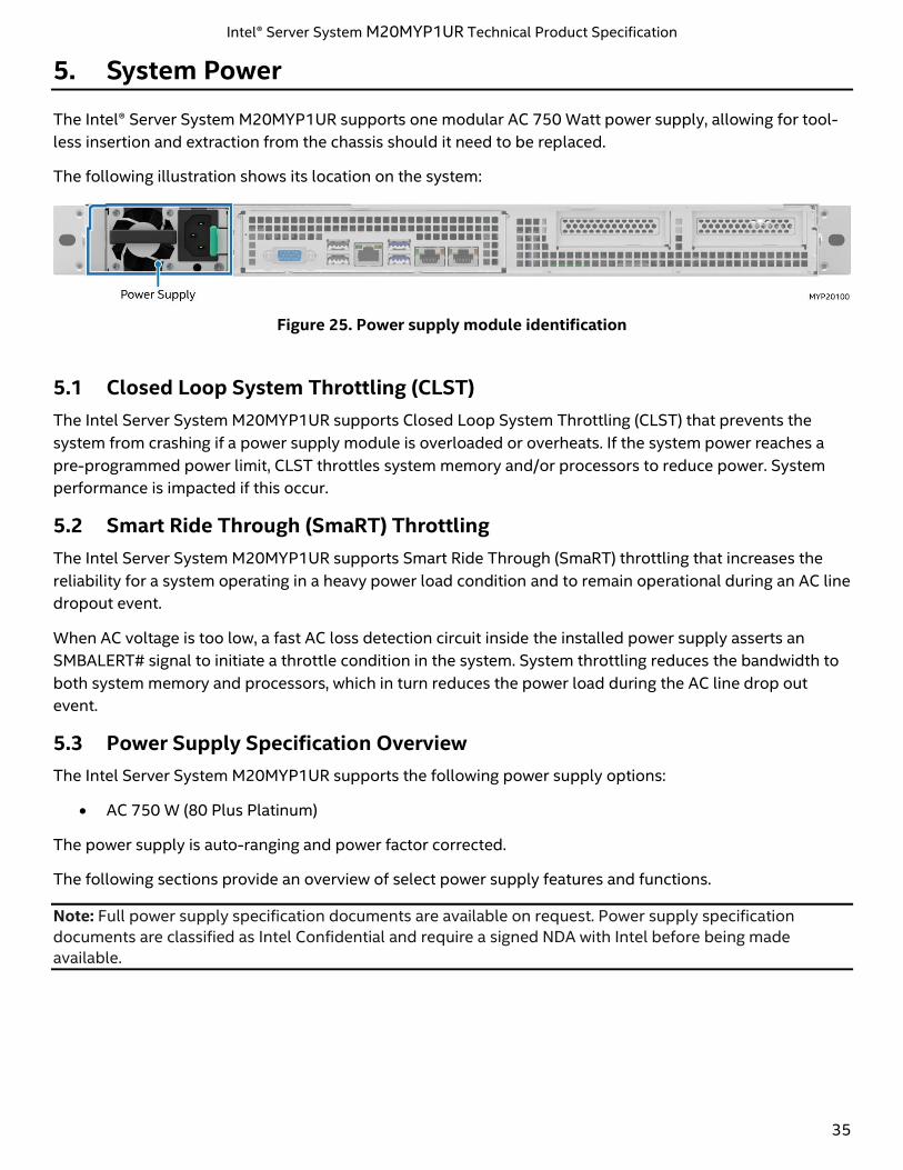
The Intel® Server System M20MYP1UR supports one modular AC 750 Watt power supply, allowing for tool-
less insertion and extraction from the chassis should it need to be replaced.
The following illustration shows its location on the system:
Figure 25. Power supply module identification
5.1 Closed Loop System Throttling (CLST)
The Intel Server System M20MYP1UR supports Closed Loop System Throttling (CLST) that prevents the
system from crashing if a power supply module is overloaded or overheats. If the system power reaches a
pre-programmed power limit, CLST throttles system memory and/or processors to reduce power. System
performance is impacted if this occur.
5.2 Smart Ride Through (SmaRT) Throttling
The Intel Server System M20MYP1UR supports Smart Ride Through (SmaRT) throttling that increases the
reliability for a system operating in a heavy power load condition and to remain operational during an AC line
dropout event.
When AC voltage is too low, a fast AC loss detection circuit inside the installed power supply asserts an
SMBALERT# signal to initiate a throttle condition in the system. System throttling reduces the bandwidth to
both system memory and processors, which in turn reduces the power load during the AC line drop out
event.
5.3 Power Supply Specification Overview
The Intel Server System M20MYP1UR supports the following power supply options:
• AC 750 W (80 Plus Platinum)
The power supply is auto-ranging and power factor corrected.
The following sections provide an overview of select power supply features and functions.
Note: Full power supply specification documents are available on request. Power supply specification
documents are classified as Intel Confidential and require a signed NDA with Intel before being made
available.
Intel® Server System M20MYP1UR Technical Product Specification
36
5.3.1 Power Supply Module Efficiency
The power supply is rated to meet specific power efficiency limits based on the 80-PLUS* Platinum power
efficiency rating.
The following table defines the required minimum power efficiency levels based on the 80-PLUS Platinum
efficiency rating at specified power load conditions: 100%, 50%, 20%, and 10%
The AC power supply efficiency is tested over an AC input voltage range of 115 VAC to 220 VAC.
Table 10. 750 W AC power supply option efficiency (80 PLUS* Platinum)
Loading 100% of maximum 50% of maximum 20% of maximum 10% of maximum
Minimum
Efficiency 92% 94% 92% 88%
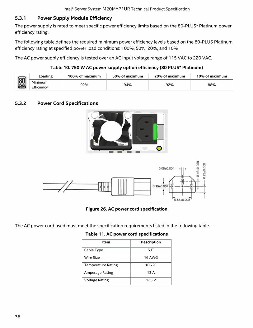
5.3.2 Power Cord Specifications
Figure 26. AC power cord specification
The AC power cord used must meet the specification requirements listed in the following table.
Table 11. AC power cord specifications
Item Description
Cable Type SJT
Wire Size 16 AWG
Temperature Rating 105 ºC
Amperage Rating 13 A
Voltage Rating 125 V
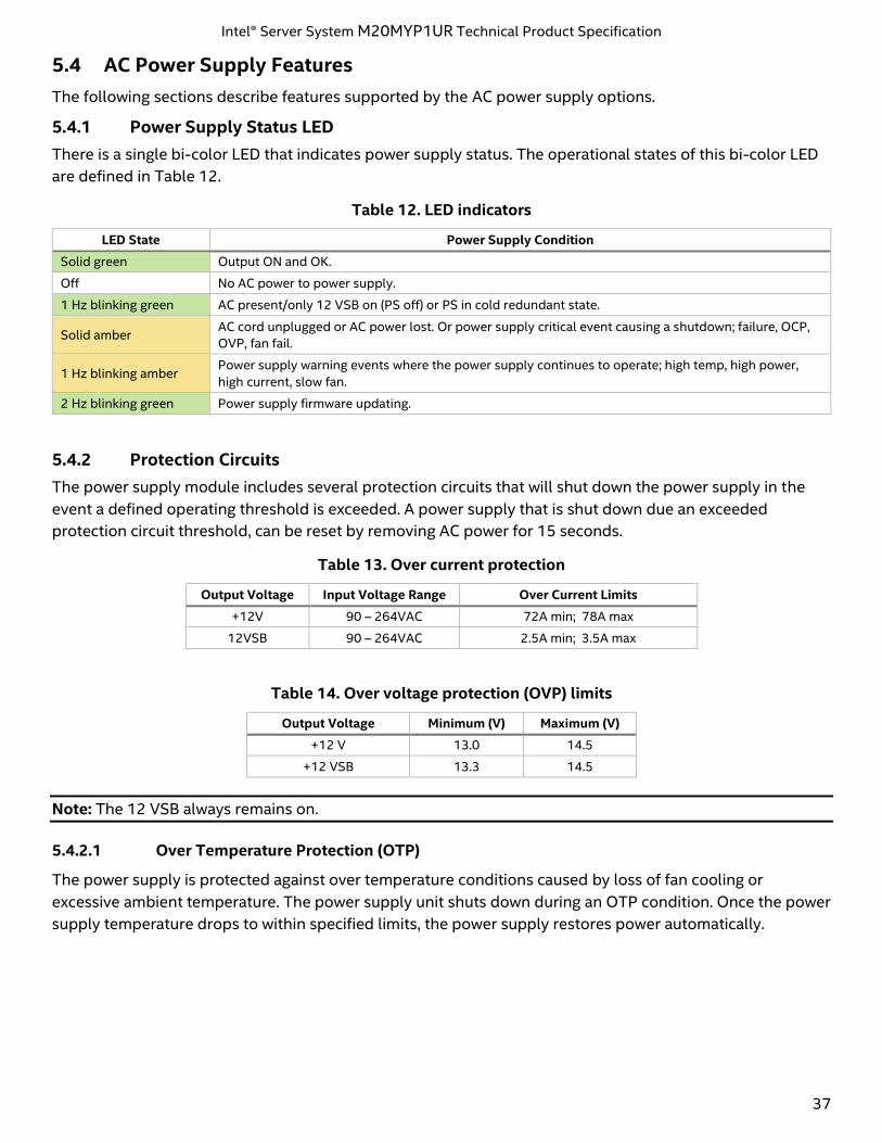
Intel® Server System M20MYP1UR Technical Product Specification
37
5.4 AC Power Supply Features
The following sections describe features supported by the AC power supply options.
5.4.1 Power Supply Status LED
There is a single bi-color LED that indicates power supply status. The operational states of this bi-color LED
are defined in Table 12.
Table 12. LED indicators
LED State Power Supply Condition
Solid green Output ON and OK.
Off No AC power to power supply.
1 Hz blinking green AC present/only 12 VSB on (PS off) or PS in cold redundant state.
Solid amber AC cord unplugged or AC power lost. Or power supply critical event causing a shutdown; failure, OCP,
OVP, fan fail.
1 Hz blinking amber Power supply warning events where the power supply continues to operate; high temp, high power,
high current, slow fan.
2 Hz blinking green Power supply firmware updating.
5.4.2 Protection Circuits
The power supply module includes several protection circuits that will shut down the power supply in the
event a defined operating threshold is exceeded. A power supply that is shut down due an exceeded
protection circuit threshold, can be reset by removing AC power for 15 seconds.
Table 13. Over current protection
Output Voltage Input Voltage Range Over Current Limits
+12V 90 – 264VAC 72A min; 78A max
12VSB 90 – 264VAC 2.5A min; 3.5A max
Table 14. Over voltage protection (OVP) limits
Output Voltage Minimum (V) Maximum (V)
+12 V 13.0 14.5
+12 VSB 13.3 14.5
Note: The 12 VSB always remains on.
5.4.2.1 Over Temperature Protection (OTP)
The power supply is protected against over temperature conditions caused by loss of fan cooling or
excessive ambient temperature. The power supply unit shuts down during an OTP condition. Once the power
supply temperature drops to within specified limits, the power supply restores power automatically.
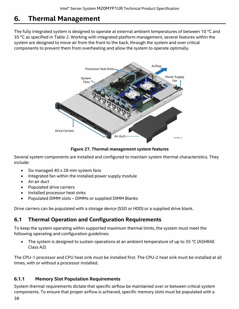
Intel® Server System M20MYP1UR Technical Product Specification
38
6. Thermal Management
The fully integrated system is designed to operate at external ambient temperatures of between 10 °C and
35 °C as specified in Table 2. Working with integrated platform management, several features within the
system are designed to move air from the front to the back, through the system and over critical
components to prevent them from overheating and allow the system to operate optimally.
Figure 27. Thermal management system features
Several system components are installed and configured to maintain system thermal characteristics. They
include:
• Six managed 40 x 28 mm system fans
• Integrated fan within the installed power supply module
• An air duct
• Populated drive carriers
• Installed processor heat sinks
• Populated DIMM slots – DIMMs or supplied DIMM Blanks
Drive carriers can be populated with a storage device (SSD or HDD) or a supplied drive blank.
6.1 Thermal Operation and Configuration Requirements
To keep the system operating within supported maximum thermal limits, the system must meet the
following operating and configuration guidelines:
• The system is designed to sustain operations at an ambient temperature of up to 35 °C (ASHRAE
Class A2)
The CPU-1 processor and CPU heat sink must be installed first. The CPU-2 heat sink must be installed at all
times, with or without a processor installed.
6.1.1 Memory Slot Population Requirements
System thermal requirements dictate that specific airflow be maintained over or between critical system
components. To ensure that proper airflow is achieved, specific memory slots must be populated with a
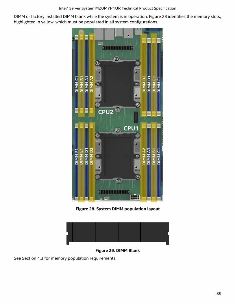
Intel® Server System M20MYP1UR Technical Product Specification
39
DIMM or factory installed DIMM blank while the system is in operation. Figure 28 identifies the memory slots,
highlighted in yellow, which must be populated in all system configurations.
Figure 28. System DIMM population layout
Figure 29. DIMM Blank
See Section 4.3 for memory population requirements.
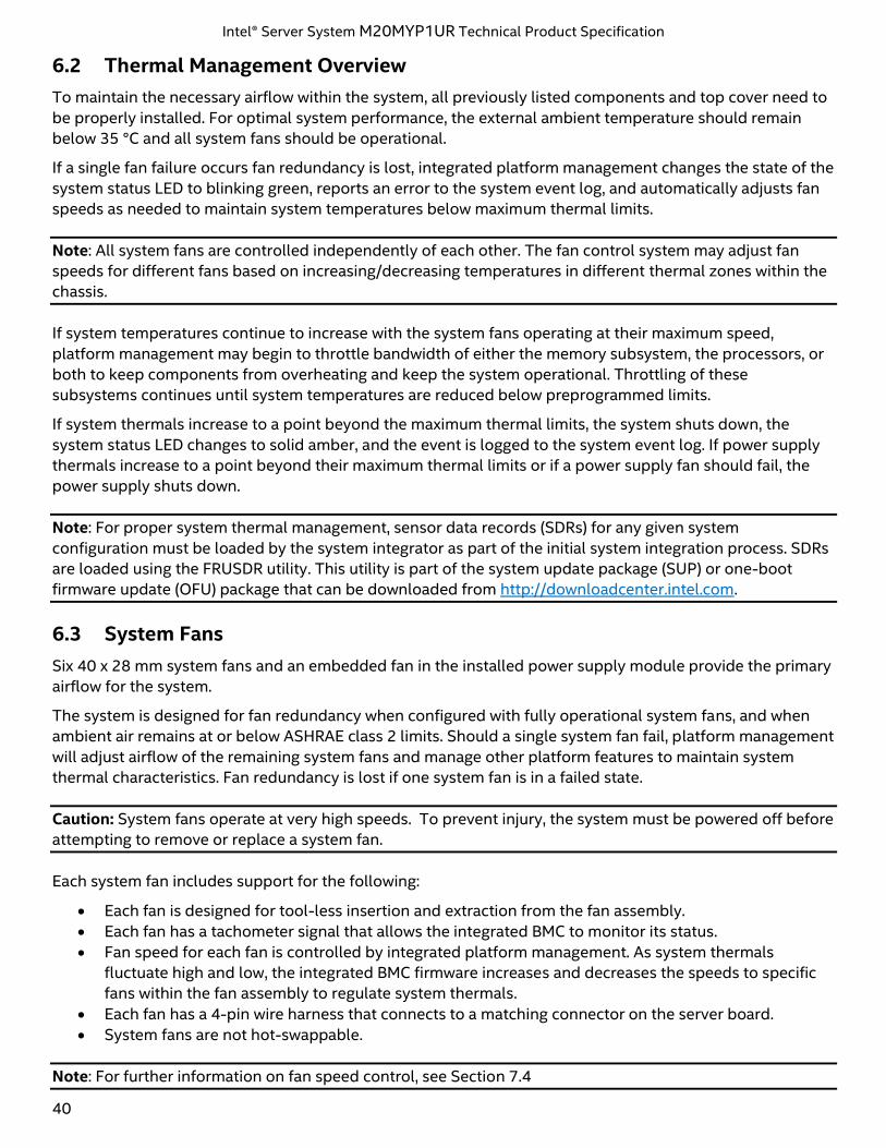
Intel® Server System M20MYP1UR Technical Product Specification
40
6.2 Thermal Management Overview
To maintain the necessary airflow within the system, all previously listed components and top cover need to
be properly installed. For optimal system performance, the external ambient temperature should remain
below 35 °C and all system fans should be operational.
If a single fan failure occurs fan redundancy is lost, integrated platform management changes the state of the
system status LED to blinking green, reports an error to the system event log, and automatically adjusts fan
speeds as needed to maintain system temperatures below maximum thermal limits.
Note: All system fans are controlled independently of each other. The fan control system may adjust fan
speeds for different fans based on increasing/decreasing temperatures in different thermal zones within the
chassis.
If system temperatures continue to increase with the system fans operating at their maximum speed,
platform management may begin to throttle bandwidth of either the memory subsystem, the processors, or
both to keep components from overheating and keep the system operational. Throttling of these
subsystems continues until system temperatures are reduced below preprogrammed limits.
If system thermals increase to a point beyond the maximum thermal limits, the system shuts down, the
system status LED changes to solid amber, and the event is logged to the system event log. If power supply
thermals increase to a point beyond their maximum thermal limits or if a power supply fan should fail, the
power supply shuts down.
Note: For proper system thermal management, sensor data records (SDRs) for any given system
configuration must be loaded by the system integrator as part of the initial system integration process. SDRs
are loaded using the FRUSDR utility. This utility is part of the system update package (SUP) or one-boot
firmware update (OFU) package that can be downloaded from http://downloadcenter.intel.com.
6.3 System Fans
Six 40 x 28 mm system fans and an embedded fan in the installed power supply module provide the primary
airflow for the system.
The system is designed for fan redundancy when configured with fully operational system fans, and when
ambient air remains at or below ASHRAE class 2 limits. Should a single system fan fail, platform management
will adjust airflow of the remaining system fans and manage other platform features to maintain system
thermal characteristics. Fan redundancy is lost if one system fan is in a failed state.
Caution: System fans operate at very high speeds. To prevent injury, the system must be powered off before
attempting to remove or replace a system fan.
Each system fan includes support for the following:
• Each fan is designed for tool-less insertion and extraction from the fan assembly.
• Each fan has a tachometer signal that allows the integrated BMC to monitor its status.
• Fan speed for each fan is controlled by integrated platform management. As system thermals
fluctuate high and low, the integrated BMC firmware increases and decreases the speeds to specific
fans within the fan assembly to regulate system thermals.
• Each fan has a 4-pin wire harness that connects to a matching connector on the server board.
• System fans are not hot-swappable.
Note: For further information on fan speed control, see Section 7.4
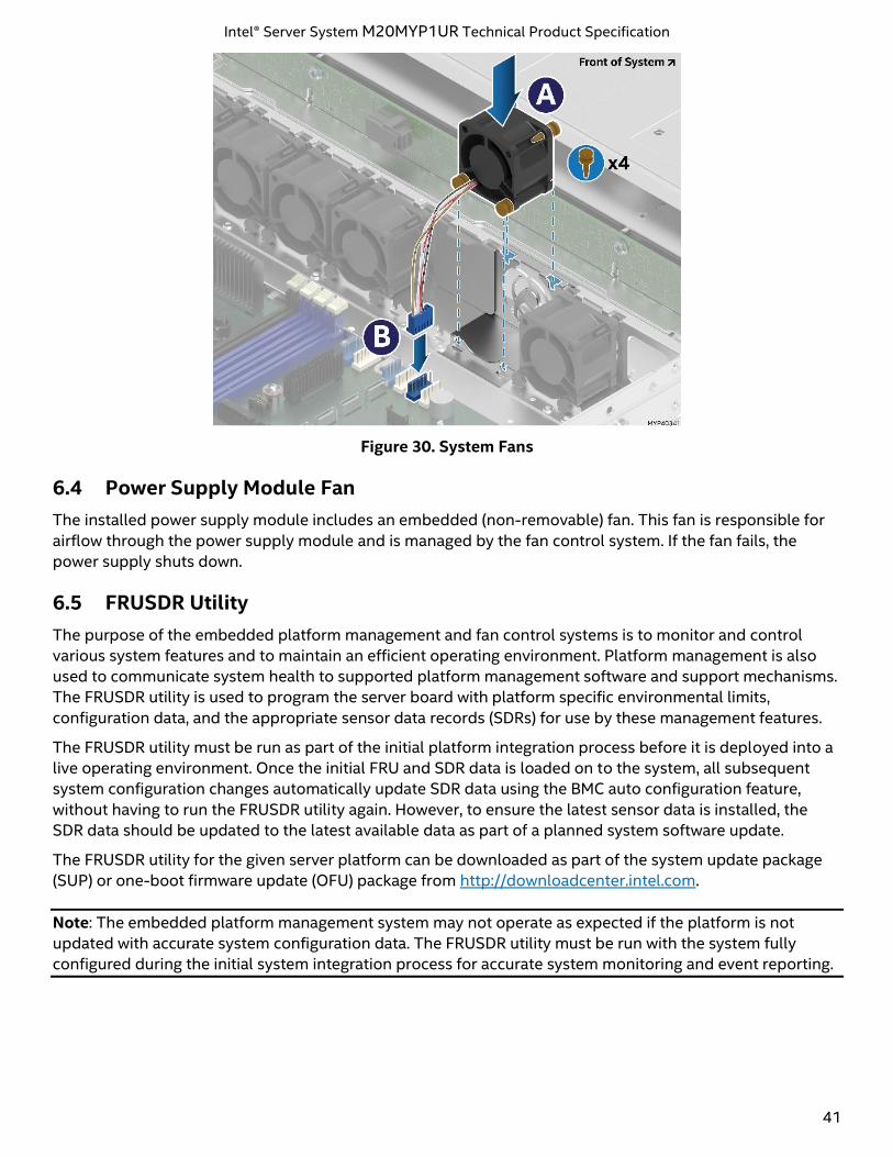
Intel® Server System M20MYP1UR Technical Product Specification
41
Figure 30. System Fans
6.4 Power Supply Module Fan
The installed power supply module includes an embedded (non-removable) fan. This fan is responsible for
airflow through the power supply module and is managed by the fan control system. If the fan fails, the
power supply shuts down.
6.5 FRUSDR Utility
The purpose of the embedded platform management and fan control systems is to monitor and control
various system features and to maintain an efficient operating environment. Platform management is also
used to communicate system health to supported platform management software and support mechanisms.
The FRUSDR utility is used to program the server board with platform specific environmental limits,
configuration data, and the appropriate sensor data records (SDRs) for use by these management features.
The FRUSDR utility must be run as part of the initial platform integration process before it is deployed into a
live operating environment. Once the initial FRU and SDR data is loaded on to the system, all subsequent
system configuration changes automatically update SDR data using the BMC auto configuration feature,
without having to run the FRUSDR utility again. However, to ensure the latest sensor data is installed, the
SDR data should be updated to the latest available data as part of a planned system software update.
The FRUSDR utility for the given server platform can be downloaded as part of the system update package
(SUP) or one-boot firmware update (OFU) package from http://downloadcenter.intel.com.
Note: The embedded platform management system may not operate as expected if the platform is not
updated with accurate system configuration data. The FRUSDR utility must be run with the system fully
configured during the initial system integration process for accurate system monitoring and event reporting.
Intel® Server System M20MYP1UR Technical Product Specification
42
7. Platform Management
This chapter provides a high-level overview of the platform management features and functionality
implemented on the server board.
Note: The Intel® Server System BMC Firmware External Product Specification (EPS) and the Intel® Server
System BIOS External Product Specification (EPS) for Intel® Server Products based on Intel® Xeon® processor
Scalable family should be referenced for more in-depth and design-level platform management information.
Platform management is supported by several hardware and software components integrated on the server
board that work together to:
• Control system functions – power system, ACPI, system reset control, system initialization, front panel
interface, system event log.
• Monitor various board and system sensors and regulate platform thermals and performance to
maintain (when possible) server functionality in the event of component failure and/or
environmentally stressed conditions.
• Monitor and report system health.
• Provide an interface for Intel® server management software applications.
7.1 Management Feature Set Overview
The following sections outline features that the integrated BMC firmware can support. Support and
utilization for some features is dependent on the server platform in which the server board is integrated and
any additional system level components and options that may be installed.
7.1.1 IPMI 2.0 Features Overview
The baseboard management controller (BMC) supports the following IPMI 2.0 features:
• IPMI watchdog timer.
• Messaging support, including command bridging and user/session support.
• Chassis device functionality, including power/reset control and BIOS boot flags support.
• Event receiver device to receive and process events from other platform subsystems.
• Access to system Field Replaceable Unit (FRU) devices using IPMI FRU commands.
• System Event Log (SEL) device functionality including SEL Severity Tracking and Extended SEL.
• Storage of and access to system Sensor Data Records (SDRs).
• Sensor device management and polling to monitor and report system health.
• IPMI interfaces:
o Host interfaces including system management software (SMS) with receive message queue
support and server management mode (SMM).
o Intelligent platform management bus (IPMB) interface.
o LAN interface that supports the IPMI-over-LAN protocol (RMCP, RMCP+).
• Serial-over-LAN (SOL).
• ACPI state synchronization to state changes provided by the BIOS.
• Initialization and runtime self-tests including making results available to external entities.
See also the Intelligent Platform Management Interface Specification Second Generation v2.0.
Intel® Server System M20MYP1UR Technical Product Specification
43
7.1.2 Non-IPMI Features Overview
The BMC supports the following non-IPMI features:
• In-circuit BMC firmware update.
• Fault resilient booting (FRB) including FRB2 supported by the watchdog timer functionality.
• Chassis intrusion detection (dependent on platform support).
• Fan speed control with SDR, fan redundancy monitoring, and support.
• Enhancements to fan speed control.
• Test commands for setting and getting platform signal states.
• Diagnostic beep codes for fault conditions.
• System globally unique identifier (GUID) storage and retrieval.
• Front panel management including system status LED and chassis ID LED (turned on using a front
panel button or command), secure lockout of certain front panel functionality, and button press
monitoring.
• Power state retention.
• Power fault analysis.
• Intel® Light-Guided Diagnostics.
• Power unit management including support for power unit sensor and handling of power-good
dropout conditions.
• DIMM temperature monitoring facilitating new sensors and improved acoustic management using the
closed-loop fan control algorithm, taking into account DIMM temperature readings.
• Sending and responding to Address Resolution Protocols (ARPs) (supported on embedded NICs).
• Dynamic Host Configuration Protocol (DHCP) (supported on embedded NICs).
• Platform environment control interface (PECI) thermal management support.
• Email alerting.
• Support for embedded web server UI in Basic Manageability feature set.
• Enhancements to embedded web server.
o Human-readable SEL.
o Additional system configurability.
o Additional system monitoring capability.
o Enhanced online help.
• Integrated keyboard, video, and mouse (KVM).
• Enhancements to KVM redirection.
o Support for higher resolution.
• Integrated Remote Media Redirection.
• Lightweight Directory Access Protocol (LDAP) support.
• Intel® Intelligent Power Node Manager support.
• Embedded platform debug feature which allows capture of detailed data for later analysis.
• Provisioning and inventory enhancements.
o Inventory data/system information export (partial SMBIOS table).
• DCMI 1.5 compliance (product SKU specific).
• Management support for Power Management Bus (PMBus*) 1.2 compliant power supplies.
• BMC data repository (managed data region feature).
• System airflow monitoring.
• Exit air temperature monitoring.
• Ethernet controller thermal monitoring.
• Global aggregate temperature margin sensor.
• Memory thermal management.
• Power supply fan sensors.
• ENERGY STAR* server support.
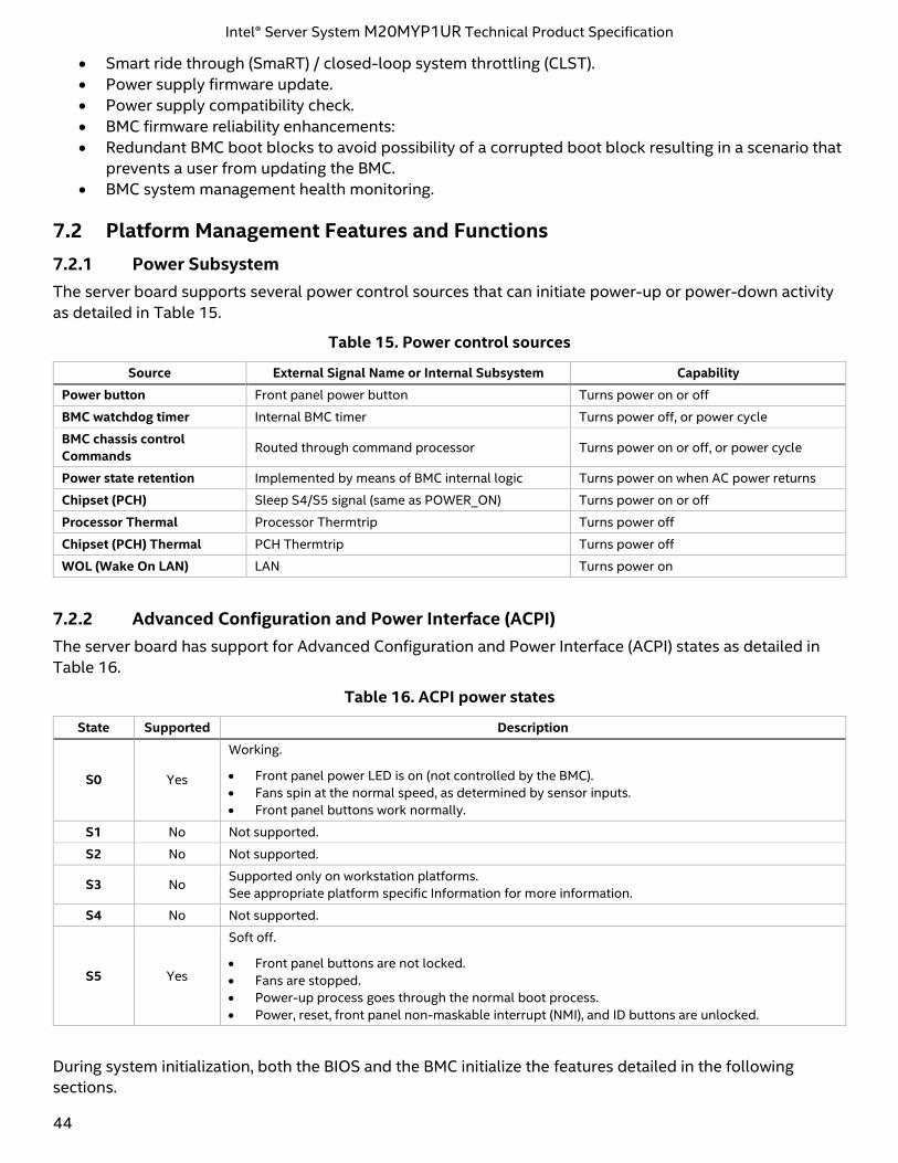
Intel® Server System M20MYP1UR Technical Product Specification
44
• Smart ride through (SmaRT) / closed-loop system throttling (CLST).
• Power supply firmware update.
• Power supply compatibility check.
• BMC firmware reliability enhancements:
• Redundant BMC boot blocks to avoid possibility of a corrupted boot block resulting in a scenario that
prevents a user from updating the BMC.
• BMC system management health monitoring.
7.2 Platform Management Features and Functions
7.2.1 Power Subsystem
The server board supports several power control sources that can initiate power-up or power-down activity
as detailed in Table 15.
Table 15. Power control sources
Source External Signal Name or Internal Subsystem Capability
Power button Front panel power button Turns power on or off
BMC watchdog timer Internal BMC timer Turns power off, or power cycle
BMC chassis control
Commands Routed through command processor Turns power on or off, or power cycle
Power state retention Implemented by means of BMC internal logic Turns power on when AC power returns
Chipset (PCH) Sleep S4/S5 signal (same as POWER_ON) Turns power on or off
Processor Thermal Processor Thermtrip Turns power off
Chipset (PCH) Thermal PCH Thermtrip Turns power off
WOL (Wake On LAN) LAN Turns power on
7.2.2 Advanced Configuration and Power Interface (ACPI)
The server board has support for Advanced Configuration and Power Interface (ACPI) states as detailed in
Table 16.
Table 16. ACPI power states
State Supported Description
S0 Yes
Working.
• Front panel power LED is on (not controlled by the BMC).
• Fans spin at the normal speed, as determined by sensor inputs.
• Front panel buttons work normally.
S1 No Not supported.
S2 No Not supported.
S3 No Supported only on workstation platforms.
See appropriate platform specific Information for more information.
S4 No Not supported.
S5 Yes
Soft off.
• Front panel buttons are not locked.
• Fans are stopped.
• Power-up process goes through the normal boot process.
• Power, reset, front panel non-maskable interrupt (NMI), and ID buttons are unlocked.
During system initialization, both the BIOS and the BMC initialize the features detailed in the following
sections.
Intel® Server System M20MYP1UR Technical Product Specification
45
7.2.2.1 Processor Tcontrol Setting
Processors used with this chipset implement a feature called Tcontrol that provides a processor-specific
value that can be used to adjust the fan-control behavior to achieve optimum cooling and acoustics. The
BMC reads these from the processor through a PECI proxy mechanism provided by the Intel® Management
Engine (Intel® ME). The BMC uses these values as part of the fan-speed-control algorithm.
7.2.2.2 Fault Resilient Booting (FRB)
Fault resilient booting (FRB) is a set of BIOS and BMC algorithms and hardware support that allow a
multiprocessor system to boot, even if the bootstrap processor (BSP) fails. Only FRB-2 is supported using
watchdog timer commands.
FRB-2 refers to the FRB algorithm that detects system failures during POST. The BIOS uses the BMC
watchdog timer to back up its operation during POST. The BIOS configures the watchdog timer to indicate
that the BIOS is using the timer for the FRB-2 phase of the boot operation.
After the BIOS has identified and saved the BSP information, it sets the FRB-2 timer use bit and loads the
watchdog timer with the new timeout interval.
If the watchdog timer expires while the watchdog use bit is set to FRB-2, the BMC (if so configured) logs a
watchdog expiration event showing the FRB-2 timeout in the event data bytes. The BMC then hard resets the
system, assuming the BIOS-selected reset as the watchdog timeout action.
The BIOS is responsible for disabling the FRB-2 timeout before initiating the option ROM scan and before
displaying a request for a boot password. If the processor fails and causes an FRB-2 timeout, the BMC resets
the system.
The BIOS gets the watchdog expiration status from the BMC. If the status shows an expired FRB-2 timer, the
BIOS enters the failure in the system event log (SEL). In the OEM bytes entry in the SEL, the last POST code
generated during the previous boot attempt is written. FRB-2 failure is not reflected in the processor status
sensor value.
The FRB-2 failure does not affect the front panel LEDs.
7.2.2.3 Post Code Display
The BMC, upon receiving standby power, initializes internal hardware to monitor port 80h (POST code)
writes. Data written to port 80h is output to the system POST LEDs.
The BMC will deactivate POST LEDs after POST completes.
7.2.3 Watchdog Timer
The BMC implements a fully IPMI 2.0 compatible watchdog timer. For details, see the Intelligent Platform
Management Interface Specification Second Generation v2.0. The NMI/diagnostic interrupt for an IPMI 2.0
watchdog timer is associated with an NMI. A watchdog pre-timeout SMI or equivalent signal assertion is not
supported.
7.2.4 System Event Log (SEL)
The BMC implements the system event log as specified in the Intelligent Platform Management Interface
Specification, Version 2.0. The SEL is accessible regardless of the system power state through the BMC's in-
band and out-of-band interfaces.
The BMC allocates 95,231 bytes (approximately 93 KB) of non-volatile storage space to store system events.
The SEL timestamps may not be in order. Up to 3,639 SEL records can be stored at a time. Because the SEL is
circular, any command that results in an overflow of the SEL beyond the allocated space overwrites the
oldest entries in the SEL, while setting the overflow flag.
Intel® Server System M20MYP1UR Technical Product Specification
46
7.3 Sensor Monitoring
The BMC monitors system hardware and reports system health. The information gathered from physical
sensors is translated into IPMI sensors as part of the IPMI sensor model. The BMC also reports various
system state changes by maintaining virtual sensors that are not specifically tied to physical hardware. This
section describes general aspects of BMC sensor management as well as describing how specific sensor
types are modeled. Unless otherwise specified, the term “sensor” refers to the IPMI sensor model definition
of a sensor.
• Sensor scanning
• BIOS event-only sensors
• Margin sensors
• IPMI watchdog sensor
• BMC watchdog sensor
• BMC system management health monitoring
• VR watchdog timer
• System airflow monitoring sensors - valid for Intel® Server Chassis only
• Fan monitoring sensors
• Thermal monitoring sensors
• Voltage monitoring sensors
• CATERR sensor
• LAN leash event monitoring
• CMOS battery monitoring
• NMI (diagnostic interrupt) sensor
7.3.1 Sensor Re-arm Behavior
Sensors can be re-armed, either manually or automatically. An automatic re-arm sensor re-arms (clears) the
assertion event state for a threshold or offset if that threshold or offset is de-asserted after having been
asserted. This allows a subsequent assertion of the threshold or an offset to generate a new event and
associated side-effect. An example side-effect is boosting fans due to an upper critical threshold crossing of
a temperature sensor. The event state and the input state (value) of the sensor track each other. Most
sensors are auto re-arm type.
A manual re-arm sensor does not clear the assertion state even when the threshold or offset becomes de-
asserted. In this case, the event state and the input state (value) of the sensor do not track each other. The
event assertion state is sticky. The following methods can be used to re-arm a sensor:
• Automatic re-arm – Only applies to sensors that are designated as auto re-arm.
• IPMI command – Re-arm sensor event.
• BMC internal method – The BMC may re-arm certain sensors due to a trigger condition. For example,
some sensors may be re-armed due to a system reset. A BMC reset re-arms all sensors.
• System reset or DC power cycle re-arms all system fan sensors.
7.3.2 Thermal Monitoring
The BMC provides monitoring of component and board temperature sensing devices. This monitoring
capability is instantiated in the form of IPMI analog/threshold or discrete sensors, depending on the nature
of the measurement.
For analog/threshold sensors, except for processor temperature sensors, critical and non-critical thresholds
(upper and lower) are set through SDRs and event generation enabled for both assertion and de-assertion
events.
For discrete sensors, both assertion and de-assertion event generation are enabled.
Intel® Server System M20MYP1UR Technical Product Specification
47
Mandatory monitoring of platform thermal sensors includes:
• Inlet temperature (physical sensor is typically on system front panel or hard disk drive (HDD)
backplane)
• Board ambient thermal sensors
• Processor temperature
• Memory (DIMM) temperature
• Processor Voltage Regulator-Down (VRD) hot monitoring
• Power supply unit (PSU) inlet temperature (only supported for PMBus*-compliant PSUs)
Additionally, the BMC firmware may create virtual sensors that are based on a combination or aggregation of
multiple physical thermal sensors and applications of a mathematical formula to thermal or power sensor
readings.
7.4 Standard Fan Management
The BMC controls and monitors the system fans. Each fan is associated with a fan speed sensor that detects
fan failure and may also be associated with a fan presence sensor. For redundant fan configurations, the fan
failure and presence status determines the fan redundancy sensor state.
The system fans are divided into fan domains, each of which has a separate fan speed control signal and a
separate configurable fan control policy. A fan domain can have a set of temperature and fan sensors
associated with it. These are used to determine the current fan domain state.
A fan domain has three states: sleep, boost, and nominal. The sleep and boost states have fixed (but
configurable through OEM SDRs) fan speeds associated with them. The nominal state has a variable speed
determined by the fan domain policy. An OEM SDR record is used to configure the fan domain policy.
The fan domain state is controlled by several factors. The factors for the boost state are listed below in order
of precedence, high to low.
• An associated fan is in a critical state or missing. The SDR describes which fan domains are boosted in
response to an increase in system temperature. If a fan is removed when the system is in fans-off
mode, it is not detected and there is not any fan boost until the system comes out of fans-off mode.
• Any associated temperature sensor is in a critical state. The SDR describes which temperature-
threshold violations cause fan boost for each fan domain.
• The BMC is in firmware update mode, or the operational firmware is corrupted.
If any of the above conditions apply, the fans are set to a fixed boost state speed.
A fan domain’s nominal fan speed can be configured as static (fixed value) or controlled by the state of one
or more associated temperature sensors.
7.4.1 Fan Domains
System fan speeds are controlled through pulse width modulation (PWM) signals that are driven separately
for each domain by integrated PWM hardware. Fan speed is changed by adjusting the duty cycle that is the
percentage of time the signal is driven high in each pulse.
The BMC controls the average duty cycle of each PWM signal through direct manipulation of the integrated
PWM control registers. The same device may drive multiple PWM signals.
7.4.2 Fan Redundancy Detection
The BMC supports redundant fan monitoring and implements a fan redundancy sensor. A fan redundancy
sensor generates events when its associated set of fans transitions between redundant and non-redundant
states, as determined by the number and health of the fans. The definition of fan redundancy is
Intel® Server System M20MYP1UR Technical Product Specification
48
configuration dependent. The BMC allows redundancy to be configured on a per fan redundancy sensor
basis through OEM SDR records.
A fan failure up to the number of redundant fans specified in the SDR in a fan configuration is a non-critical
failure and is reflected in the front panel status. A fan failure that exceeds the number of redundant fans is a
non-fatal, insufficient-resources condition and is reflected in the front panel status as a non-fatal error.
Redundancy is checked only when the system is in the DC-on state. Fan redundancy changes that occur
when the system is DC-off or when AC is removed are not logged until the system is turned on.
7.4.3 Thermal and Acoustic Management
This feature refers to enhanced fan management to keep the system optimally cooled while reducing the
amount of noise generated by the system fans. Aggressive acoustics standards might require a trade-off
between fan speed and system performance parameters that contribute to the cooling requirements,
primarily memory bandwidth. The BIOS, BMC, and SDRs work together to provide control over how this
trade-off is determined.
This capability requires the BMC to access temperature sensors on the individual memory DIMMs.
Additionally, closed-loop thermal throttling is only supported for DIMMs with temperature sensors.
7.4.4 Thermal Sensor Input to Fan Speed Control
The BMC uses various IPMI sensors as an input to the fan speed control. Some of the sensors are IPMI
models of actual physical sensors, whereas some are virtual sensors whose values are derived from physical
sensors using calculations and/or tabular information.
The following IPMI thermal sensors are used as the input to the fan speed control:
• Baseboard temperature sensors
• Processor digital thermal sensor (DTS)-specification margin sensors
• DIMM thermal margin sensors
• Exit air temperature sensor
• PCH temperature sensor
• Global aggregate thermal margin sensors
• SSB (Intel® C620 Series Chipset) temperature sensor
• Onboard Ethernet controller temperature sensors (support for this is specific to the Ethernet
controller being used)
• Onboard SAS controller temperature sensors (when available)
• CPU VR temperature sensor
• DIMM VR temperature sensor
• BMC temperature sensor
• DIMM VRM temperature sensor
The following figure shows a high-level representation of the fan speed control structure that determines fan
speed.
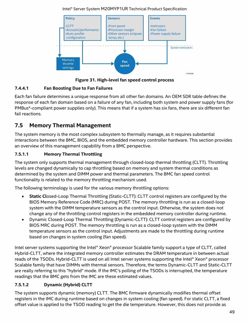
Intel® Server System M20MYP1UR Technical Product Specification
49
Figure 31. High-level fan speed control process
7.4.4.1 Fan Boosting Due to Fan Failures
Each fan failure determines a unique response from all other fan domains. An OEM SDR table defines the
response of each fan domain based on a failure of any fan, including both system and power supply fans (for
PMBus*-compliant power supplies only). This means that if a system has six fans, there are six different fan
fail reactions.
7.5 Memory Thermal Management
The system memory is the most complex subsystem to thermally manage, as it requires substantial
interactions between the BMC, BIOS, and the embedded memory controller hardware. This section provides
an overview of this management capability from a BMC perspective.
7.5.1.1 Memory Thermal Throttling
The system only supports thermal management through closed-loop thermal throttling (CLTT). Throttling
levels are changed dynamically to cap throttling based on memory and system thermal conditions as
determined by the system and DIMM power and thermal parameters. The BMC fan speed control
functionality is related to the memory throttling mechanism used.
The following terminology is used for the various memory throttling options:
• Static Closed-Loop Thermal Throttling (Static-CLTT): CLTT control registers are configured by the
BIOS Memory Reference Code (MRC) during POST. The memory throttling is run as a closed-loop
system with the DIMM temperature sensors as the control input. Otherwise, the system does not
change any of the throttling control registers in the embedded memory controller during runtime.
• Dynamic Closed-Loop Thermal Throttling (Dynamic-CLTT): CLTT control registers are configured by
BIOS MRC during POST. The memory throttling is run as a closed-loop system with the DIMM
temperature sensors as the control input. Adjustments are made to the throttling during runtime
based on changes in system cooling (fan speed).
Intel server systems supporting the Intel® Xeon® processor Scalable family support a type of CLTT, called
Hybrid-CLTT, where the integrated memory controller estimates the DRAM temperature in between actual
reads of the TSODs. Hybrid-CLTT is used on all Intel server systems supporting the Intel® Xeon® processor
Scalable family that have DIMMs with thermal sensors. Therefore, the terms Dynamic-CLTT and Static-CLTT
are really referring to this “hybrid” mode. If the IMC’s polling of the TSODs is interrupted, the temperature
readings that the BMC gets from the IMC are these estimated values.
7.5.1.2 Dynamic (Hybrid) CLTT
The system supports dynamic (memory) CLTT. The BMC firmware dynamically modifies thermal offset
registers in the IMC during runtime based on changes in system cooling (fan speed). For static CLTT, a fixed
offset value is applied to the TSOD reading to get the die temperature. However, this does not provide as
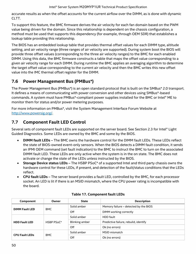
Intel® Server System M20MYP1UR Technical Product Specification
50
accurate results as when the offset accounts for the current airflow over the DIMM, as is done with dynamic
CLTT.
To support this feature, the BMC firmware derives the air velocity for each fan domain based on the PWM
value being driven for the domain. Since this relationship is dependent on the chassis configuration, a
method must be used that supports this dependency (for example, through OEM SDR) that establishes a
lookup table providing this relationship.
The BIOS has an embedded lookup table that provides thermal offset values for each DIMM type, altitude
setting, and air velocity range (three ranges of air velocity are supported). During system boot the BIOS will
provide three offset values (corresponding to the three air velocity ranges) to the BMC for each enabled
DIMM. Using this data, the BMC firmware constructs a table that maps the offset value corresponding to a
given air velocity range for each DIMM. During runtime the BMC applies an averaging algorithm to determine
the target offset value corresponding to the current air velocity and then the BMC writes this new offset
value into the IMC thermal offset register for the DIMM.
7.6 Power Management Bus (PMBus*)
The Power Management Bus (PMBus*) is an open standard protocol that is built on the SMBus* 2.0 transport.
It defines a means of communicating with power conversion and other devices using SMBus*-based
commands. A system must have PMBus*-compliant power supplies installed for the BMC or Intel® ME to
monitor them for status and/or power metering purposes.
For more information on PMBus*, visit the System Management Interface Forum Website at
http://www.powersig.org/.
7.7 Component Fault LED Control
Several sets of component fault LEDs are supported on the server board. See Section 2.3 for Intel® Light
Guided Diagnostics. Some LEDs are owned by the BMC and some by the BIOS.
• DIMM fault LEDs – The BMC owns the hardware control for the DIMM fault LEDs. These LEDs reflect
the state of BIOS-owned event-only sensors. When the BIOS detects a DIMM fault condition, it sends
an IPMI OEM command (set fault indication) to the BMC to instruct the BMC to turn on the associated
DIMM fault LED. These LEDs are only active when the system is in the on state. The BMC does not
activate or change the state of the LEDs unless instructed by the BIOS.
• Storage Device status LEDs – The HSBP PSoC* of a supported Intel and third party chassis owns the
hardware control for these LEDs, if present, and detection of the fault/status conditions that the LEDs
reflect.
• CPU fault LEDs – The server board provides a fault LED, controlled by the BMC, for each processor
socket. An LED is lit if there is an MSID mismatch, where the CPU power rating is incompatible with
the board.
Table 17. Component fault LEDs
Component Owner State Description
DIMM Fault LED BMC Solid amber Memory failure – detected by the BIOS
Off DIMM working correctly
HDD Fault LED HSBP PSoC*
Solid amber HDD fault
Blinking amber Predictive failure, rebuild, identify
Off Ok (no errors)
CPU Fault LEDs BMC Solid amber MSID mismatch
Off Ok (no errors)
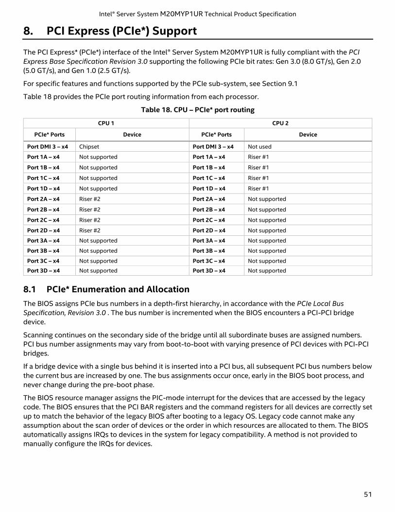
Intel® Server System M20MYP1UR Technical Product Specification
51
8. PCI Express (PCIe*) Support
The PCI Express* (PCIe*) interface of the Intel® Server System M20MYP1UR is fully compliant with the PCI
Express Base Specification Revision 3.0 supporting the following PCIe bit rates: Gen 3.0 (8.0 GT/s), Gen 2.0
(5.0 GT/s), and Gen 1.0 (2.5 GT/s).
For specific features and functions supported by the PCIe sub-system, see Section 9.1
Table 18 provides the PCIe port routing information from each processor.
Table 18. CPU – PCIe* port routing
CPU 1 CPU 2
PCIe* Ports Device PCIe* Ports Device
Port DMI 3 – x4 Chipset Port DMI 3 – x4 Not used
Port 1A – x4 Not supported Port 1A – x4 Riser #1
Port 1B – x4 Not supported Port 1B – x4 Riser #1
Port 1C – x4 Not supported Port 1C – x4 Riser #1
Port 1D – x4 Not supported Port 1D – x4 Riser #1
Port 2A – x4 Riser #2 Port 2A – x4 Not supported
Port 2B – x4 Riser #2 Port 2B – x4 Not supported
Port 2C – x4 Riser #2 Port 2C – x4 Not supported
Port 2D – x4 Riser #2 Port 2D – x4 Not supported
Port 3A – x4 Not supported Port 3A – x4 Not supported
Port 3B – x4 Not supported Port 3B – x4 Not supported
Port 3C – x4 Not supported Port 3C – x4 Not supported
Port 3D – x4 Not supported Port 3D – x4 Not supported
8.1 PCIe* Enumeration and Allocation
The BIOS assigns PCIe bus numbers in a depth-first hierarchy, in accordance with the PCIe Local Bus
Specification, Revision 3.0 . The bus number is incremented when the BIOS encounters a PCI-PCI bridge
device.
Scanning continues on the secondary side of the bridge until all subordinate buses are assigned numbers.
PCI bus number assignments may vary from boot-to-boot with varying presence of PCI devices with PCI-PCI
bridges.
If a bridge device with a single bus behind it is inserted into a PCI bus, all subsequent PCI bus numbers below
the current bus are increased by one. The bus assignments occur once, early in the BIOS boot process, and
never change during the pre-boot phase.
The BIOS resource manager assigns the PIC-mode interrupt for the devices that are accessed by the legacy
code. The BIOS ensures that the PCI BAR registers and the command registers for all devices are correctly set
up to match the behavior of the legacy BIOS after booting to a legacy OS. Legacy code cannot make any
assumption about the scan order of devices or the order in which resources are allocated to them. The BIOS
automatically assigns IRQs to devices in the system for legacy compatibility. A method is not provided to
manually configure the IRQs for devices.
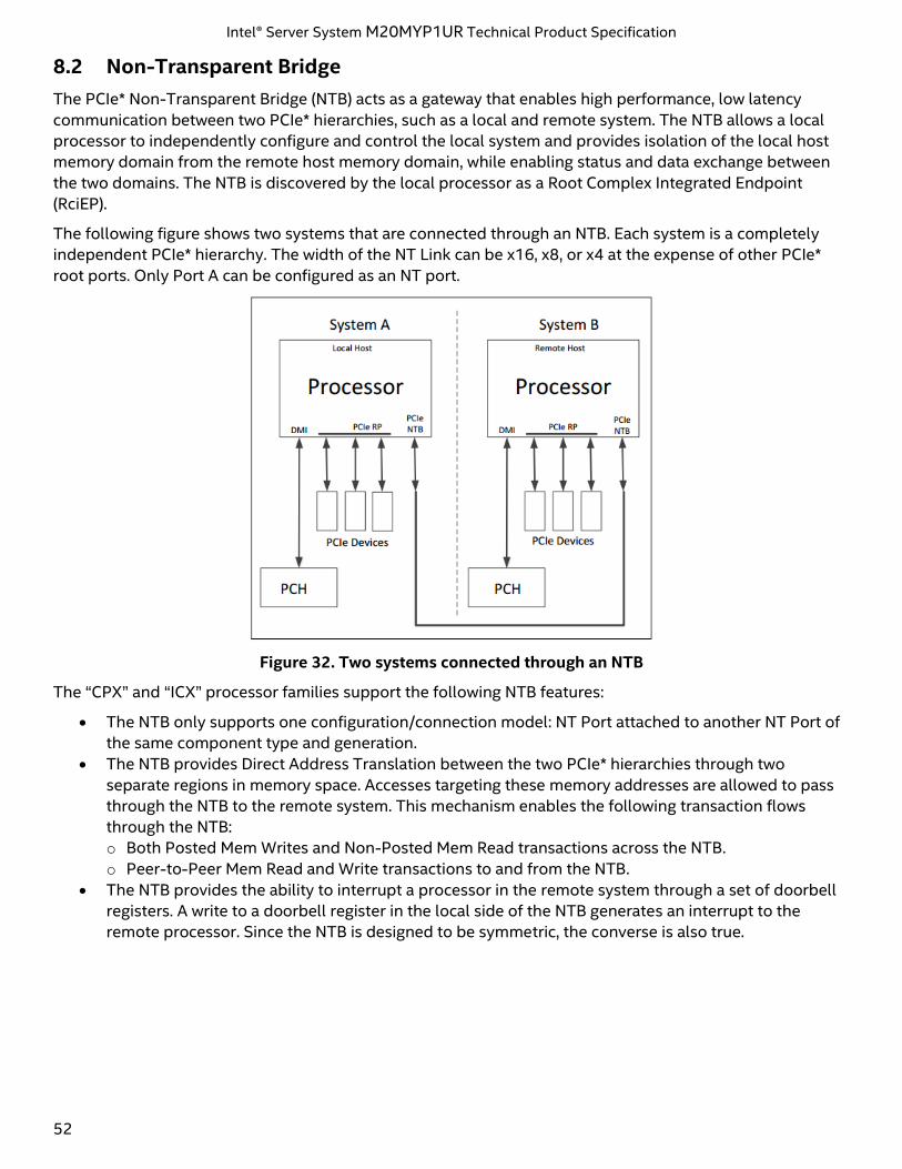
Intel® Server System M20MYP1UR Technical Product Specification
52
8.2 Non-Transparent Bridge
The PCIe* Non-Transparent Bridge (NTB) acts as a gateway that enables high performance, low latency
communication between two PCIe* hierarchies, such as a local and remote system. The NTB allows a local
processor to independently configure and control the local system and provides isolation of the local host
memory domain from the remote host memory domain, while enabling status and data exchange between
the two domains. The NTB is discovered by the local processor as a Root Complex Integrated Endpoint
(RciEP).
The following figure shows two systems that are connected through an NTB. Each system is a completely
independent PCIe* hierarchy. The width of the NT Link can be x16, x8, or x4 at the expense of other PCIe*
root ports. Only Port A can be configured as an NT port.
Figure 32. Two systems connected through an NTB
The “CPX” and “ICX” processor families support the following NTB features:
• The NTB only supports one configuration/connection model: NT Port attached to another NT Port of
the same component type and generation.
• The NTB provides Direct Address Translation between the two PCIe* hierarchies through two
separate regions in memory space. Accesses targeting these memory addresses are allowed to pass
through the NTB to the remote system. This mechanism enables the following transaction flows
through the NTB:
o Both Posted Mem Writes and Non-Posted Mem Read transactions across the NTB.
o Peer-to-Peer Mem Read and Write transactions to and from the NTB.
• The NTB provides the ability to interrupt a processor in the remote system through a set of doorbell
registers. A write to a doorbell register in the local side of the NTB generates an interrupt to the
remote processor. Since the NTB is designed to be symmetric, the converse is also true.
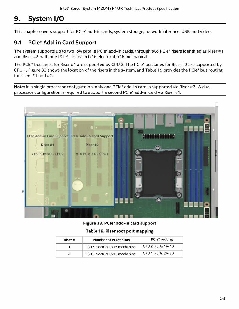
Intel® Server System M20MYP1UR Technical Product Specification
53
9. System I/O
This chapter covers support for PCIe* add-in cards, system storage, network interface, USB, and video.
9.1 PCIe* Add-in Card Support
The system supports up to two low profile PCIe* add-in cards, through two PCIe* risers identified as Riser #1
and Riser #2, with one PCIe* slot each (x16 electrical, x16 mechanical).
The PCIe* bus lanes for Riser #1 are supported by CPU 2. The PCIe* bus lanes for Riser #2 are supported by
CPU 1. Figure 33 shows the location of the risers in the system, and Table 19 provides the PCIe* bus routing
for risers #1 and #2.
Note: In a single processor configuration, only one PCIe* add-in card is supported via Riser #2. A dual
processor configuration is required to support a second PCIe* add-in card via Riser #1.
Figure 33. PCIe* add-in card support
Table 19. Riser root port mapping
Riser # Number of PCIe* Slots PCIe* routing
1 1 (x16 electrical, x16 mechanical CPU 2, Ports 1A-1D
2 1 (x16 electrical, x16 mechanical CPU 1, Ports 2A-2D
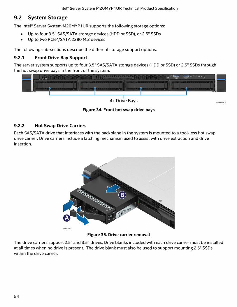
Intel® Server System M20MYP1UR Technical Product Specification
54
9.2 System Storage
The Intel® Server System M20MYP1UR supports the following storage options:
• Up to four 3.5” SAS/SATA storage devices (HDD or SSD), or 2.5” SSDs
• Up to two PCIe*/SATA 2280 M.2 devices
The following sub-sections describe the different storage support options.
9.2.1 Front Drive Bay Support
The server system supports up to four 3.5” SAS/SATA storage devices (HDD or SSD) or 2.5” SSDs through
the hot swap drive bays in the front of the system.
Figure 34. Front hot swap drive bays
9.2.2 Hot Swap Drive Carriers
Each SAS/SATA drive that interfaces with the backplane in the system is mounted to a tool-less hot swap
drive carrier. Drive carriers include a latching mechanism used to assist with drive extraction and drive
insertion.
Figure 35. Drive carrier removal
The drive carriers support 2.5” and 3.5” drives. Drive blanks included with each drive carrier must be installed
at all times when no drive is present. The drive blank must also be used to support mounting 2.5” SSDs
within the drive carrier.
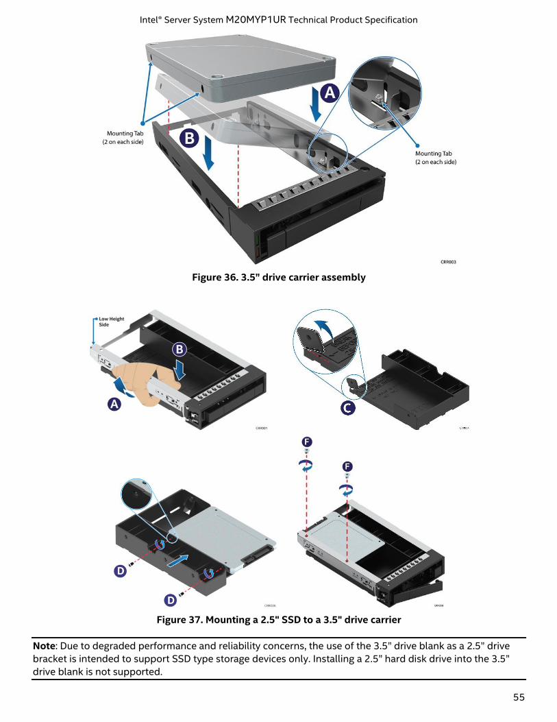
Intel® Server System M20MYP1UR Technical Product Specification
55
Figure 36. 3.5” drive carrier assembly
Figure 37. Mounting a 2.5" SSD to a 3.5" drive carrier
Note: Due to degraded performance and reliability concerns, the use of the 3.5” drive blank as a 2.5” drive
bracket is intended to support SSD type storage devices only. Installing a 2.5” hard disk drive into the 3.5”
drive blank is not supported.
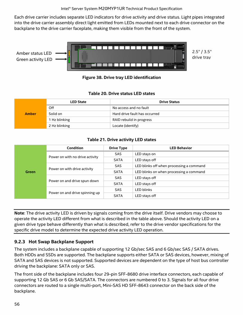
Intel® Server System M20MYP1UR Technical Product Specification
56
Each drive carrier includes separate LED indicators for drive activity and drive status. Light pipes integrated
into the drive carrier assembly direct light emitted from LEDs mounted next to each drive connector on the
backplane to the drive carrier faceplate, making them visible from the front of the system.
Figure 38. Drive tray LED identification
Table 20. Drive status LED states
Amber
LED State Drive Status
Off No access and no fault
Solid on Hard drive fault has occurred
1 Hz blinking RAID rebuild in progress
2 Hz blinking Locate (identify)
Table 21. Drive activity LED states
Green
Condition Drive Type LED Behavior
Power on with no drive activity SAS LED stays on
SATA LED stays off
Power on with drive activity SAS LED blinks off when processing a command
SATA LED blinks on when processing a command
Power on and drive spun down SAS LED stays off
SATA LED stays off
Power on and drive spinning up SAS LED blinks
SATA LED stays off
Note: The drive activity LED is driven by signals coming from the drive itself. Drive vendors may choose to
operate the activity LED different from what is described in the table above. Should the activity LED on a
given drive type behave differently than what is described, refer to the drive vendor specifications for the
specific drive model to determine the expected drive activity LED operation.
9.2.3 Hot Swap Backplane Support
The system includes a backplane capable of supporting 12 Gb/sec SAS and 6 Gb/sec SAS / SATA drives.
Both HDDs and SSDs are supported. The backplane supports either SATA or SAS devices, however, mixing of
SATA and SAS devices is not supported. Supported devices are dependent on the type of host bus controller
driving the backplane: SATA only or SAS.
The front side of the backplane includes four 29-pin SFF-8680 drive interface connectors, each capable of
supporting 12 Gb SAS or 6 Gb SAS/SATA. The connectors are numbered 0 to 3. Signals for all four drive
connectors are routed to a single multi-port, Mini-SAS HD SFF-8643 connector on the back side of the
backplane.
Amber status LED
Green activity LED
2.5” / 3.5”
drive tray
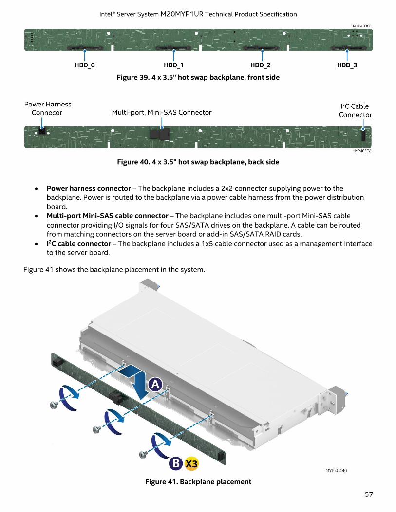
Intel® Server System M20MYP1UR Technical Product Specification
57
Figure 39. 4 x 3.5" hot swap backplane, front side
Figure 40. 4 x 3.5" hot swap backplane, back side
• Power harness connector – The backplane includes a 2x2 connector supplying power to the
backplane. Power is routed to the backplane via a power cable harness from the power distribution
board.
• Multi-port Mini-SAS cable connector – The backplane includes one multi-port Mini-SAS cable
connector providing I/O signals for four SAS/SATA drives on the backplane. A cable can be routed
from matching connectors on the server board or add-in SAS/SATA RAID cards.
• I2C cable connector – The backplane includes a 1x5 cable connector used as a management interface
to the server board.
Figure 41 shows the backplane placement in the system.
Figure 41. Backplane placement
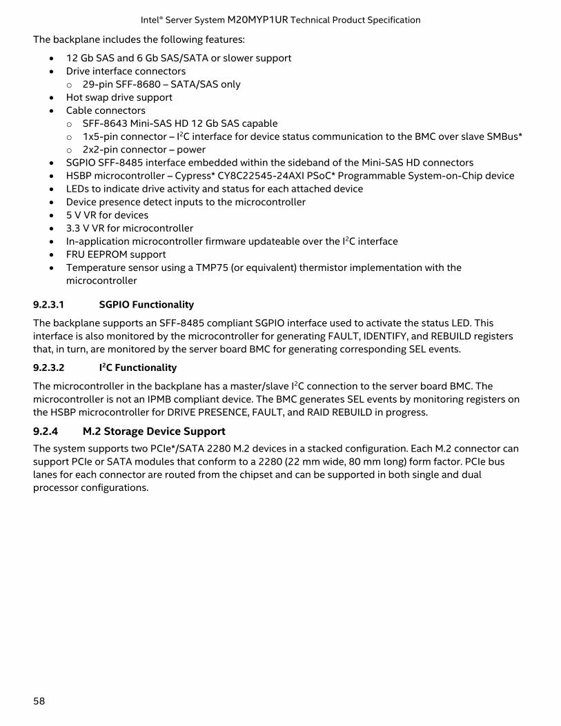
Intel® Server System M20MYP1UR Technical Product Specification
58
The backplane includes the following features:
• 12 Gb SAS and 6 Gb SAS/SATA or slower support
• Drive interface connectors
o 29-pin SFF-8680 – SATA/SAS only
• Hot swap drive support
• Cable connectors
o SFF-8643 Mini-SAS HD 12 Gb SAS capable
o 1x5-pin connector – I2C interface for device status communication to the BMC over slave SMBus*
o 2x2-pin connector – power
• SGPIO SFF-8485 interface embedded within the sideband of the Mini-SAS HD connectors
• HSBP microcontroller – Cypress* CY8C22545-24AXI PSoC* Programmable System-on-Chip device
• LEDs to indicate drive activity and status for each attached device
• Device presence detect inputs to the microcontroller
• 5 V VR for devices
• 3.3 V VR for microcontroller
• In-application microcontroller firmware updateable over the I2C interface
• FRU EEPROM support
• Temperature sensor using a TMP75 (or equivalent) thermistor implementation with the
microcontroller
9.2.3.1 SGPIO Functionality
The backplane supports an SFF-8485 compliant SGPIO interface used to activate the status LED. This
interface is also monitored by the microcontroller for generating FAULT, IDENTIFY, and REBUILD registers
that, in turn, are monitored by the server board BMC for generating corresponding SEL events.
9.2.3.2 I2C Functionality
The microcontroller in the backplane has a master/slave I2C connection to the server board BMC. The
microcontroller is not an IPMB compliant device. The BMC generates SEL events by monitoring registers on
the HSBP microcontroller for DRIVE PRESENCE, FAULT, and RAID REBUILD in progress.
9.2.4 M.2 Storage Device Support
The system supports two PCIe*/SATA 2280 M.2 devices in a stacked configuration. Each M.2 connector can
support PCIe or SATA modules that conform to a 2280 (22 mm wide, 80 mm long) form factor. PCIe bus
lanes for each connector are routed from the chipset and can be supported in both single and dual
processor configurations.
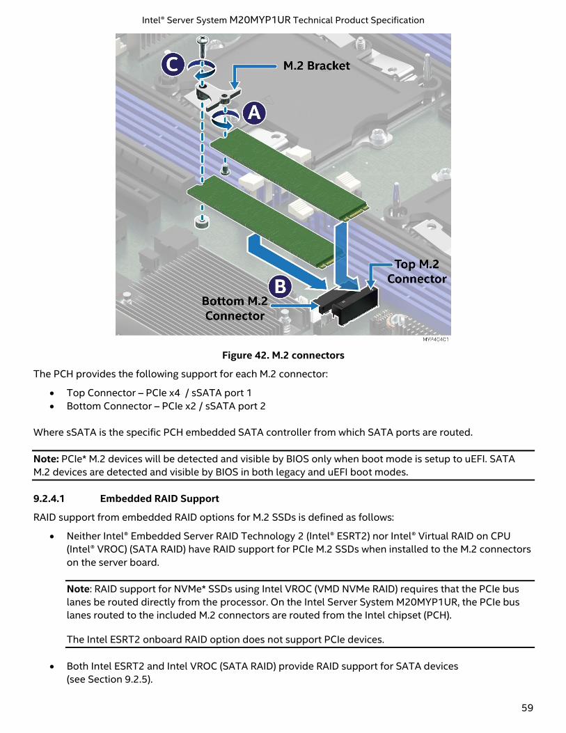
Intel® Server System M20MYP1UR Technical Product Specification
59
Figure 42. M.2 connectors
The PCH provides the following support for each M.2 connector:
• Top Connector – PCIe x4 / sSATA port 1
• Bottom Connector – PCIe x2 / sSATA port 2
Where sSATA is the specific PCH embedded SATA controller from which SATA ports are routed.
Note: PCIe* M.2 devices will be detected and visible by BIOS only when boot mode is setup to uEFI. SATA
M.2 devices are detected and visible by BIOS in both legacy and uEFI boot modes.
9.2.4.1 Embedded RAID Support
RAID support from embedded RAID options for M.2 SSDs is defined as follows:
• Neither Intel® Embedded Server RAID Technology 2 (Intel® ESRT2) nor Intel® Virtual RAID on CPU
(Intel® VROC) (SATA RAID) have RAID support for PCIe M.2 SSDs when installed to the M.2 connectors
on the server board.
Note: RAID support for NVMe* SSDs using Intel VROC (VMD NVMe RAID) requires that the PCIe bus
lanes be routed directly from the processor. On the Intel Server System M20MYP1UR, the PCIe bus
lanes routed to the included M.2 connectors are routed from the Intel chipset (PCH).
The Intel ESRT2 onboard RAID option does not support PCIe devices.
• Both Intel ESRT2 and Intel VROC (SATA RAID) provide RAID support for SATA devices
(see Section 9.2.5).
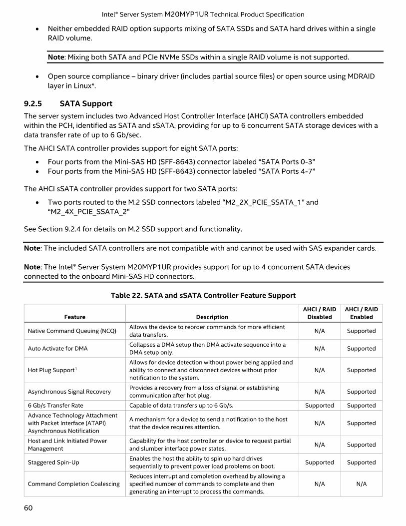
Intel® Server System M20MYP1UR Technical Product Specification
60
• Neither embedded RAID option supports mixing of SATA SSDs and SATA hard drives within a single
RAID volume.
Note: Mixing both SATA and PCIe NVMe SSDs within a single RAID volume is not supported.
• Open source compliance – binary driver (includes partial source files) or open source using MDRAID
layer in Linux*.
9.2.5 SATA Support
The server system includes two Advanced Host Controller Interface (AHCI) SATA controllers embedded
within the PCH, identified as SATA and sSATA, providing for up to 6 concurrent SATA storage devices with a
data transfer rate of up to 6 Gb/sec.
The AHCI SATA controller provides support for eight SATA ports:
• Four ports from the Mini-SAS HD (SFF-8643) connector labeled “SATA Ports 0-3”
• Four ports from the Mini-SAS HD (SFF-8643) connector labeled “SATA Ports 4-7”
The AHCI sSATA controller provides support for two SATA ports:
• Two ports routed to the M.2 SSD connectors labeled “M2_2X_PCIE_SSATA_1” and
“M2_4X_PCIE_SSATA_2”
See Section 9.2.4 for details on M.2 SSD support and functionality.
Note: The included SATA controllers are not compatible with and cannot be used with SAS expander cards.
Note: The Intel® Server System M20MYP1UR provides support for up to 4 concurrent SATA devices
connected to the onboard Mini-SAS HD connectors.
Table 22. SATA and sSATA Controller Feature Support
Feature Description
AHCI / RAID
Disabled
AHCI / RAID
Enabled
Native Command Queuing (NCQ) Allows the device to reorder commands for more efficient
data transfers. N/A Supported
Auto Activate for DMA Collapses a DMA setup then DMA activate sequence into a
DMA setup only. N/A Supported
Hot Plug Support1
Allows for device detection without power being applied and
ability to connect and disconnect devices without prior
notification to the system.
N/A Supported
Asynchronous Signal Recovery Provides a recovery from a loss of signal or establishing
communication after hot plug. N/A Supported
6 Gb/s Transfer Rate Capable of data transfers up to 6 Gb/s. Supported Supported
Advance Technology Attachment
with Packet Interface (ATAPI)
Asynchronous Notification
A mechanism for a device to send a notification to the host
that the device requires attention. N/A Supported
Host and Link Initiated Power
Management
Capability for the host controller or device to request partial
and slumber interface power states. N/A Supported
Staggered Spin-Up Enables the host the ability to spin up hard drives
sequentially to prevent power load problems on boot. Supported Supported
Command Completion Coalescing
Reduces interrupt and completion overhead by allowing a
specified number of commands to complete and then
generating an interrupt to process the commands.
N/A N/A
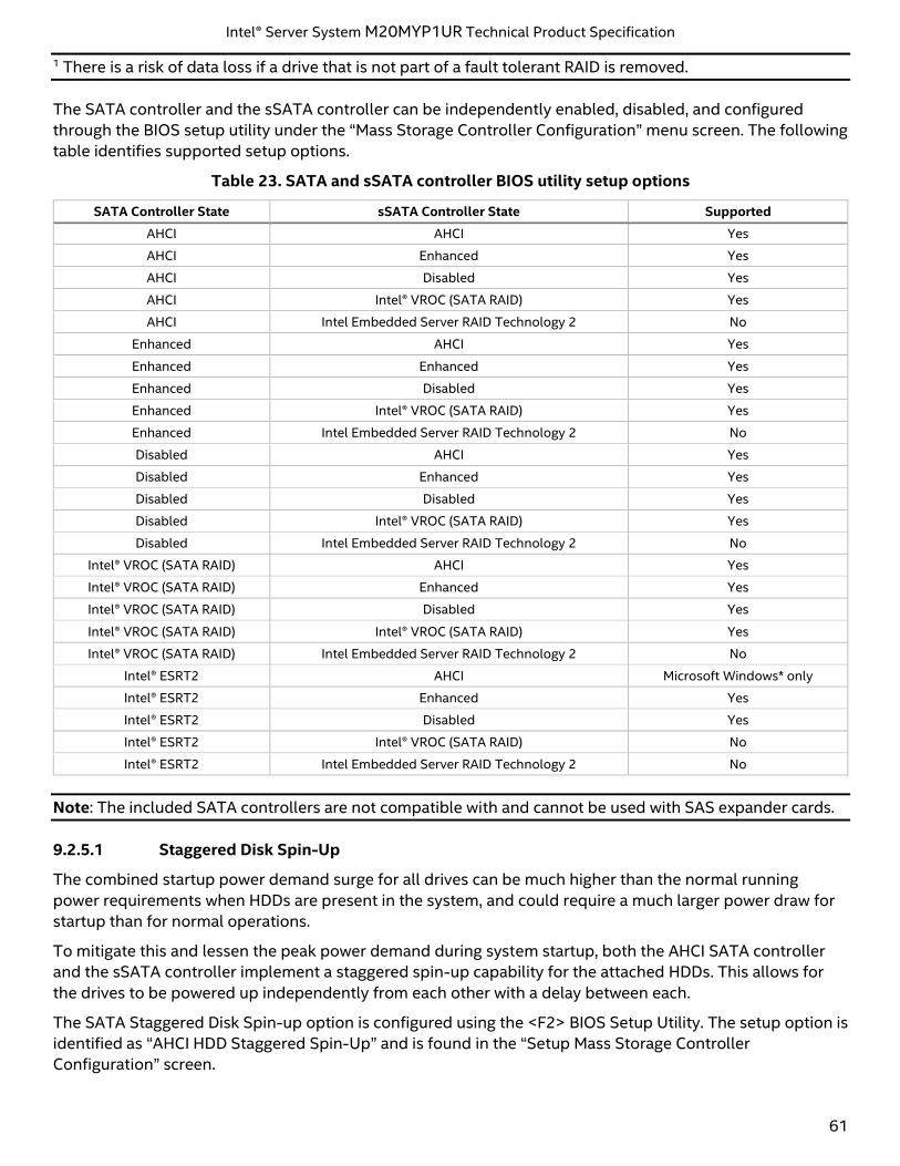
Intel® Server System M20MYP1UR Technical Product Specification
61
1 There is a risk of data loss if a drive that is not part of a fault tolerant RAID is removed.
The SATA controller and the sSATA controller can be independently enabled, disabled, and configured
through the BIOS setup utility under the “Mass Storage Controller Configuration” menu screen. The following
table identifies supported setup options.
Table 23. SATA and sSATA controller BIOS utility setup options
SATA Controller State sSATA Controller State Supported
AHCI AHCI Yes
AHCI Enhanced Yes
AHCI Disabled Yes
AHCI Intel® VROC (SATA RAID) Yes
AHCI Intel Embedded Server RAID Technology 2 No
Enhanced AHCI Yes
Enhanced Enhanced Yes
Enhanced Disabled Yes
Enhanced Intel® VROC (SATA RAID) Yes
Enhanced Intel Embedded Server RAID Technology 2 No
Disabled AHCI Yes
Disabled Enhanced Yes
Disabled Disabled Yes
Disabled Intel® VROC (SATA RAID) Yes
Disabled Intel Embedded Server RAID Technology 2 No
Intel® VROC (SATA RAID) AHCI Yes
Intel® VROC (SATA RAID) Enhanced Yes
Intel® VROC (SATA RAID) Disabled Yes
Intel® VROC (SATA RAID) Intel® VROC (SATA RAID) Yes
Intel® VROC (SATA RAID) Intel Embedded Server RAID Technology 2 No
Intel® ESRT2 AHCI Microsoft Windows* only
Intel® ESRT2 Enhanced Yes
Intel® ESRT2 Disabled Yes
Intel® ESRT2 Intel® VROC (SATA RAID) No
Intel® ESRT2 Intel Embedded Server RAID Technology 2 No
Note: The included SATA controllers are not compatible with and cannot be used with SAS expander cards.
9.2.5.1 Staggered Disk Spin-Up
The combined startup power demand surge for all drives can be much higher than the normal running
power requirements when HDDs are present in the system, and could require a much larger power draw for
startup than for normal operations.
To mitigate this and lessen the peak power demand during system startup, both the AHCI SATA controller
and the sSATA controller implement a staggered spin-up capability for the attached HDDs. This allows for
the drives to be powered up independently from each other with a delay between each.
The SATA Staggered Disk Spin-up option is configured using the <F2> BIOS Setup Utility. The setup option is
identified as “AHCI HDD Staggered Spin-Up” and is found in the “Setup Mass Storage Controller
Configuration” screen.
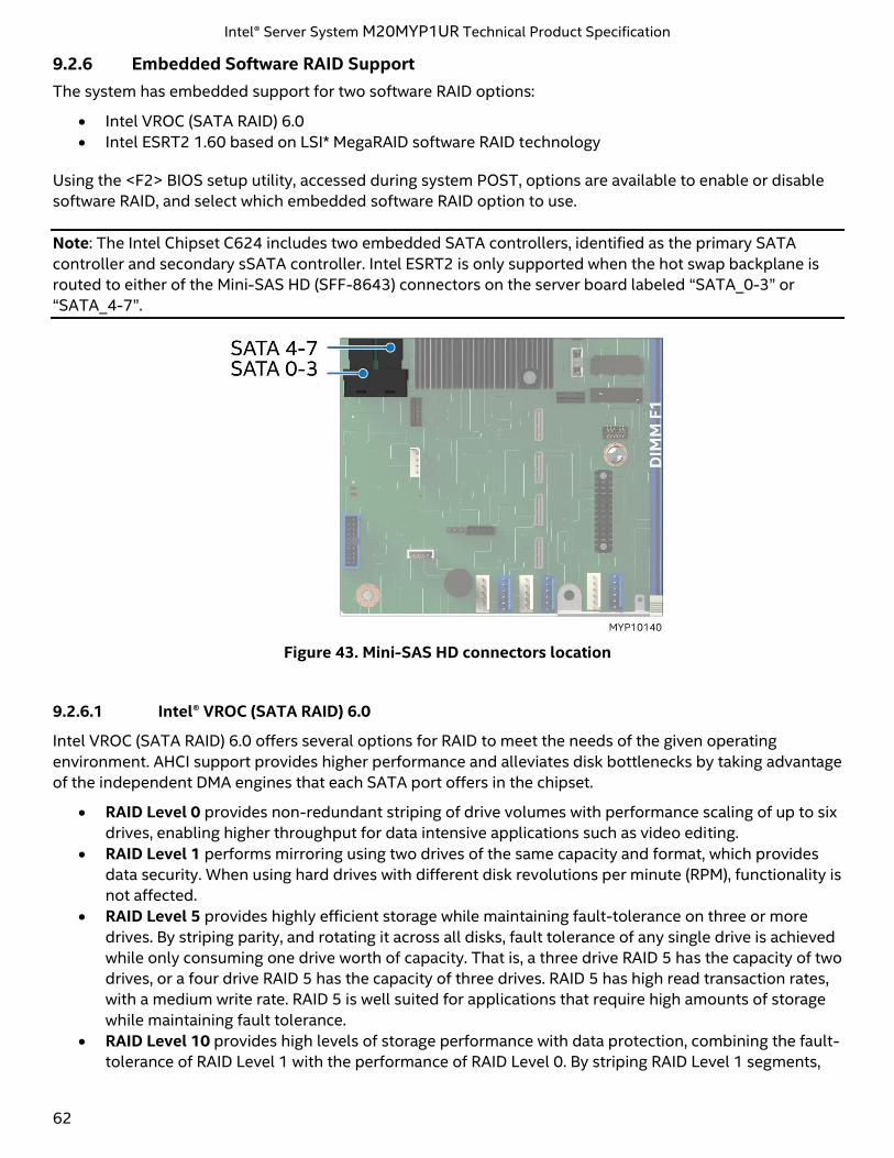
Intel® Server System M20MYP1UR Technical Product Specification
62
9.2.6 Embedded Software RAID Support
The system has embedded support for two software RAID options:
• Intel VROC (SATA RAID) 6.0
• Intel ESRT2 1.60 based on LSI* MegaRAID software RAID technology
Using the <F2> BIOS setup utility, accessed during system POST, options are available to enable or disable
software RAID, and select which embedded software RAID option to use.
Note: The Intel Chipset C624 includes two embedded SATA controllers, identified as the primary SATA
controller and secondary sSATA controller. Intel ESRT2 is only supported when the hot swap backplane is
routed to either of the Mini-SAS HD (SFF-8643) connectors on the server board labeled “SATA_0-3” or
“SATA_4-7”.
Figure 43. Mini-SAS HD connectors location
9.2.6.1 Intel® VROC (SATA RAID) 6.0
Intel VROC (SATA RAID) 6.0 offers several options for RAID to meet the needs of the given operating
environment. AHCI support provides higher performance and alleviates disk bottlenecks by taking advantage
of the independent DMA engines that each SATA port offers in the chipset.
• RAID Level 0 provides non-redundant striping of drive volumes with performance scaling of up to six
drives, enabling higher throughput for data intensive applications such as video editing.
• RAID Level 1 performs mirroring using two drives of the same capacity and format, which provides
data security. When using hard drives with different disk revolutions per minute (RPM), functionality is
not affected.
• RAID Level 5 provides highly efficient storage while maintaining fault-tolerance on three or more
drives. By striping parity, and rotating it across all disks, fault tolerance of any single drive is achieved
while only consuming one drive worth of capacity. That is, a three drive RAID 5 has the capacity of two
drives, or a four drive RAID 5 has the capacity of three drives. RAID 5 has high read transaction rates,
with a medium write rate. RAID 5 is well suited for applications that require high amounts of storage
while maintaining fault tolerance.
• RAID Level 10 provides high levels of storage performance with data protection, combining the fault-
tolerance of RAID Level 1 with the performance of RAID Level 0. By striping RAID Level 1 segments,
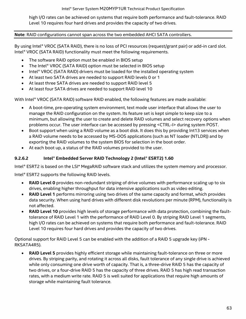
Intel® Server System M20MYP1UR Technical Product Specification
63
high I/O rates can be achieved on systems that require both performance and fault-tolerance. RAID
Level 10 requires four hard drives and provides the capacity of two drives.
Note: RAID configurations cannot span across the two embedded AHCI SATA controllers.
By using Intel® VROC (SATA RAID), there is no loss of PCI resources (request/grant pair) or add-in card slot.
Intel® VROC (SATA RAID) functionality must meet the following requirements.
• The software RAID option must be enabled in BIOS setup
• The Intel® VROC (SATA RAID) option must be selected in BIOS setup
• Intel® VROC (SATA RAID) drivers must be loaded for the installed operating system
• At least two SATA drives are needed to support RAID levels 0 or 1
• At least three SATA drives are needed to support RAID level 5
• At least four SATA drives are needed to support RAID level 10
With Intel® VROC (SATA RAID) software RAID enabled, the following features are made available:
• A boot-time, pre-operating system environment, text mode user interface that allows the user to
manage the RAID configuration on the system. Its feature set is kept simple to keep size to a
minimum, but allowing the user to create and delete RAID volumes and select recovery options when
problems occur. The user interface can be accessed by pressing <CTRL-I> during system POST.
• Boot support when using a RAID volume as a boot disk. It does this by providing Int13 services when
a RAID volume needs to be accessed by MS-DOS applications (such as NT loader (NTLDR)) and by
exporting the RAID volumes to the system BIOS for selection in the boot order.
• At each boot up, a status of the RAID volumes provided to the user.
9.2.6.2 Intel® Embedded Server RAID Technology 2 (Intel® ESRT2) 1.60
Intel® ESRT2 is based on the LSI* MegaRAID software stack and utilizes the system memory and processor.
Intel® ESRT2 supports the following RAID levels.
• RAID Level 0 provides non-redundant striping of drive volumes with performance scaling up to six
drives, enabling higher throughput for data intensive applications such as video editing.
• RAID Level 1 performs mirroring using two drives of the same capacity and format, which provides
data security. When using hard drives with different disk revolutions per minute (RPM), functionality is
not affected.
• RAID Level 10 provides high levels of storage performance with data protection, combining the fault-
tolerance of RAID Level 1 with the performance of RAID Level 0. By striping RAID Level 1 segments,
high I/O rates can be achieved on systems that require both performance and fault-tolerance. RAID
Level 10 requires four hard drives and provides the capacity of two drives.
Optional support for RAID Level 5 can be enabled with the addition of a RAID 5 upgrade key (iPN -
RKSATA4R5).
• RAID Level 5 provides highly efficient storage while maintaining fault-tolerance on three or more
drives. By striping parity, and rotating it across all disks, fault tolerance of any single drive is achieved
while only consuming one drive worth of capacity. That is, a three-drive RAID 5 has the capacity of
two drives, or a four-drive RAID 5 has the capacity of three drives. RAID 5 has high read transaction
rates, with a medium write rate. RAID 5 is well suited for applications that require high amounts of
storage while maintaining fault tolerance.
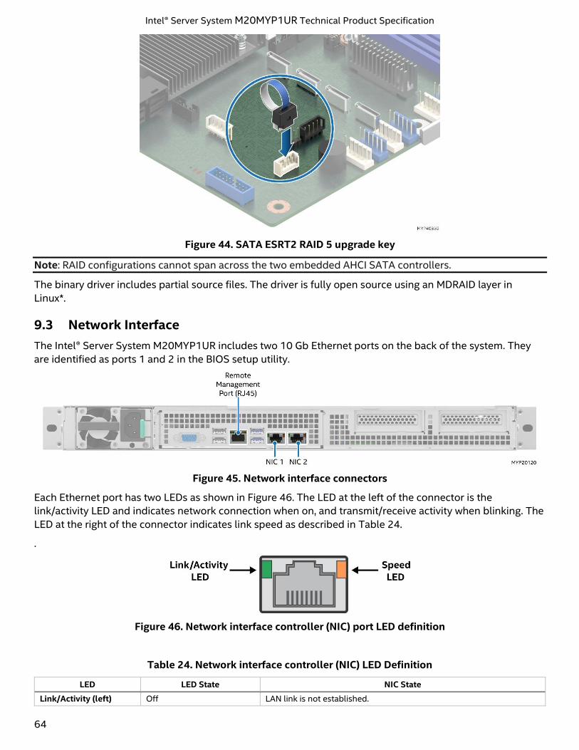
Intel® Server System M20MYP1UR Technical Product Specification
64
Figure 44. SATA ESRT2 RAID 5 upgrade key
Note: RAID configurations cannot span across the two embedded AHCI SATA controllers.
The binary driver includes partial source files. The driver is fully open source using an MDRAID layer in
Linux*.
9.3 Network Interface
The Intel® Server System M20MYP1UR includes two 10 Gb Ethernet ports on the back of the system. They
are identified as ports 1 and 2 in the BIOS setup utility.
Figure 45. Network interface connectors
Each Ethernet port has two LEDs as shown in Figure 46. The LED at the left of the connector is the
link/activity LED and indicates network connection when on, and transmit/receive activity when blinking. The
LED at the right of the connector indicates link speed as described in Table 24.
.
Figure 46. Network interface controller (NIC) port LED definition
Table 24. Network interface controller (NIC) LED Definition
LED LED State NIC State
Link/Activity (left) Off LAN link is not established.
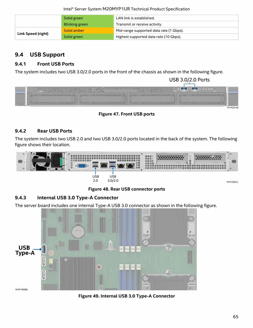
Intel® Server System M20MYP1UR Technical Product Specification
65
Solid green LAN link is established.
Blinking green Transmit or receive activity.
Link Speed (right) Solid amber Mid-range supported data rate (1 Gbps).
Solid green Highest supported data rate (10 Gbps).
9.4 USB Support
9.4.1 Front USB Ports
The system includes two USB 3.0/2.0 ports in the front of the chassis as shown in the following figure.
Figure 47. Front USB ports
9.4.2 Rear USB Ports
The system includes two USB 2.0 and two USB 3.0/2.0 ports located in the back of the system. The following
figure shows their location.
Figure 48. Rear USB connector ports
9.4.3 Internal USB 3.0 Type-A Connector
The server board includes one internal Type-A USB 3.0 connector as shown in the following figure.
Figure 49. Internal USB 3.0 Type-A Connector
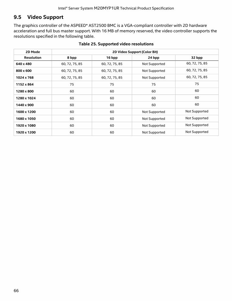
Intel® Server System M20MYP1UR Technical Product Specification
66
9.5 Video Support
The graphics controller of the ASPEED* AST2500 BMC is a VGA-compliant controller with 2D hardware
acceleration and full bus master support. With 16 MB of memory reserved, the video controller supports the
resolutions specified in the following table.
Table 25. Supported video resolutions
2D Mode 2D Video Support (Color Bit)
Resolution 8 bpp 16 bpp 24 bpp 32 bpp
640 x 480 60, 72, 75, 85 60, 72, 75, 85 Not Supported 60, 72, 75, 85
800 x 600 60, 72, 75, 85 60, 72, 75, 85 Not Supported 60, 72, 75, 85
1024 x 768 60, 72, 75, 85 60, 72, 75, 85 Not Supported 60, 72, 75, 85
1152 x 864 75 75 75 75
1280 x 800 60 60 60 60
1280 x 1024 60 60 60 60
1440 x 900 60 60 60 60
1600 x 1200 60 60 Not Supported Not Supported
1680 x 1050 60 60 Not Supported Not Supported
1920 x 1080 60 60 Not Supported Not Supported
1920 x 1200 60 60 Not Supported Not Supported
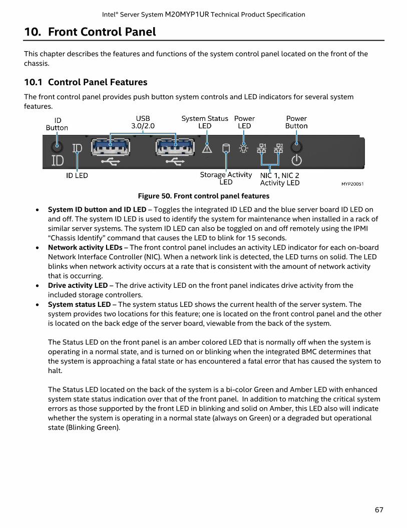
Intel® Server System M20MYP1UR Technical Product Specification
67
10. Front Control Panel
This chapter describes the features and functions of the system control panel located on the front of the
chassis.
10.1 Control Panel Features
The front control panel provides push button system controls and LED indicators for several system
features.
Figure 50. Front control panel features
• System ID button and ID LED – Toggles the integrated ID LED and the blue server board ID LED on
and off. The system ID LED is used to identify the system for maintenance when installed in a rack of
similar server systems. The system ID LED can also be toggled on and off remotely using the IPMI
“Chassis Identify” command that causes the LED to blink for 15 seconds.
• Network activity LEDs – The front control panel includes an activity LED indicator for each on-board
Network Interface Controller (NIC). When a network link is detected, the LED turns on solid. The LED
blinks when network activity occurs at a rate that is consistent with the amount of network activity
that is occurring.
• Drive activity LED – The drive activity LED on the front panel indicates drive activity from the
included storage controllers.
• System status LED – The system status LED shows the current health of the server system. The
system provides two locations for this feature; one is located on the front control panel and the other
is located on the back edge of the server board, viewable from the back of the system.
The Status LED on the front panel is an amber colored LED that is normally off when the system is
operating in a normal state, and is turned on or blinking when the integrated BMC determines that
the system is approaching a fatal state or has encountered a fatal error that has caused the system to
halt.
The Status LED located on the back of the system is a bi-color Green and Amber LED with enhanced
system state status indication over that of the front panel. In addition to matching the critical system
errors as those supported by the front LED in blinking and solid on Amber, this LED also will indicate
whether the system is operating in a normal state (always on Green) or a degraded but operational
state (Blinking Green).
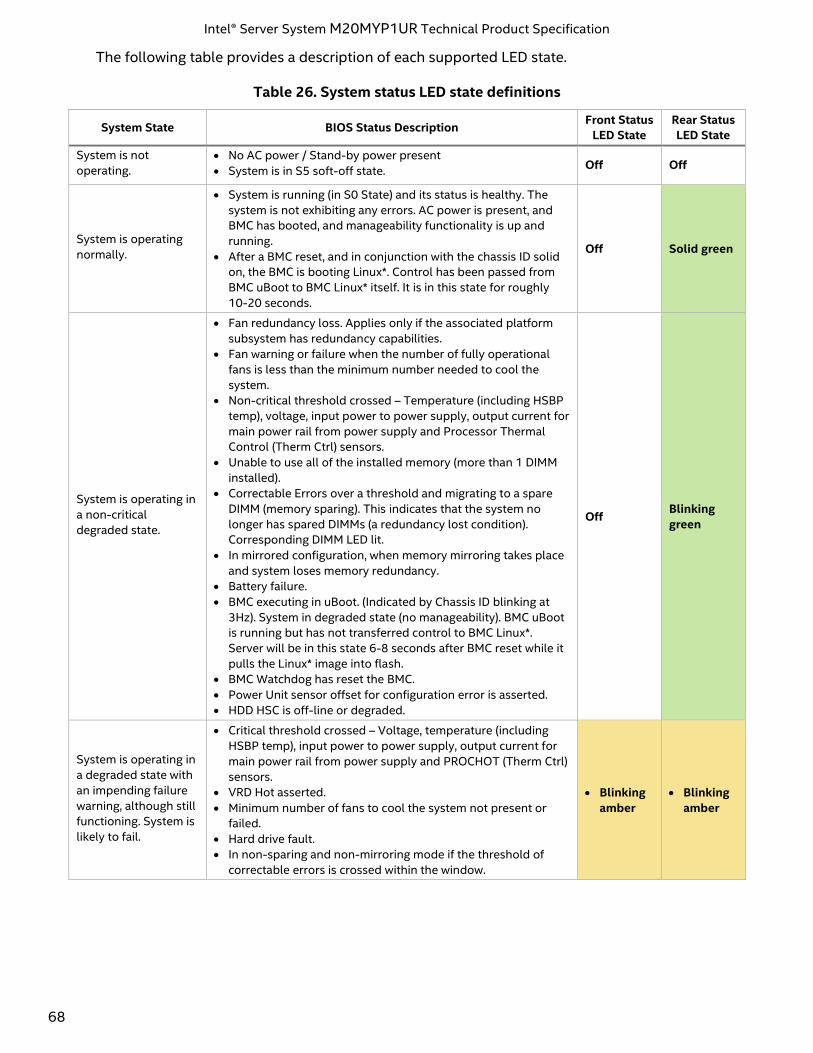
Intel® Server System M20MYP1UR Technical Product Specification
68
The following table provides a description of each supported LED state.
Table 26. System status LED state definitions
System State BIOS Status Description Front Status
LED State
Rear Status
LED State
System is not
operating.
• No AC power / Stand-by power present
• System is in S5 soft-off state. Off Off
System is operating
normally.
• System is running (in S0 State) and its status is healthy. The
system is not exhibiting any errors. AC power is present, and
BMC has booted, and manageability functionality is up and
running.
• After a BMC reset, and in conjunction with the chassis ID solid
on, the BMC is booting Linux*. Control has been passed from
BMC uBoot to BMC Linux* itself. It is in this state for roughly
10-20 seconds.
Off Solid green
System is operating in
a non-critical
degraded state.
• Fan redundancy loss. Applies only if the associated platform
subsystem has redundancy capabilities.
• Fan warning or failure when the number of fully operational
fans is less than the minimum number needed to cool the
system.
• Non-critical threshold crossed – Temperature (including HSBP
temp), voltage, input power to power supply, output current for
main power rail from power supply and Processor Thermal
Control (Therm Ctrl) sensors.
• Unable to use all of the installed memory (more than 1 DIMM
installed).
• Correctable Errors over a threshold and migrating to a spare
DIMM (memory sparing). This indicates that the system no
longer has spared DIMMs (a redundancy lost condition).
Corresponding DIMM LED lit.
• In mirrored configuration, when memory mirroring takes place
and system loses memory redundancy.
• Battery failure.
• BMC executing in uBoot. (Indicated by Chassis ID blinking at
3Hz). System in degraded state (no manageability). BMC uBoot
is running but has not transferred control to BMC Linux*.
Server will be in this state 6-8 seconds after BMC reset while it
pulls the Linux* image into flash.
• BMC Watchdog has reset the BMC.
• Power Unit sensor offset for configuration error is asserted.
• HDD HSC is off-line or degraded.
Off Blinking
green
System is operating in
a degraded state with
an impending failure
warning, although still
functioning. System is
likely to fail.
• Critical threshold crossed – Voltage, temperature (including
HSBP temp), input power to power supply, output current for
main power rail from power supply and PROCHOT (Therm Ctrl)
sensors.
• VRD Hot asserted.
• Minimum number of fans to cool the system not present or
failed.
• Hard drive fault.
• In non-sparing and non-mirroring mode if the threshold of
correctable errors is crossed within the window.
• Blinking
amber
• Blinking
amber
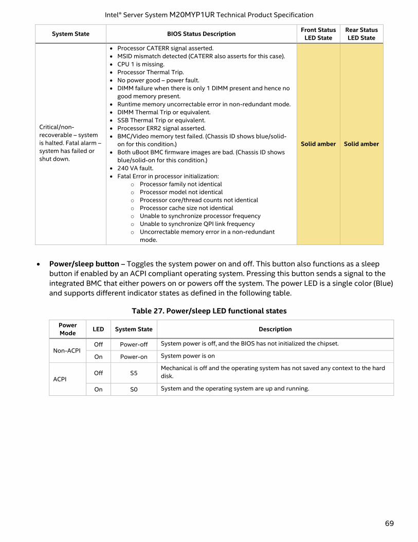
Intel® Server System M20MYP1UR Technical Product Specification
69
System State BIOS Status Description Front Status
LED State
Rear Status
LED State
Critical/non-
recoverable – system
is halted. Fatal alarm –
system has failed or
shut down.
• Processor CATERR signal asserted.
• MSID mismatch detected (CATERR also asserts for this case).
• CPU 1 is missing.
• Processor Thermal Trip.
• No power good – power fault.
• DIMM failure when there is only 1 DIMM present and hence no
good memory present.
• Runtime memory uncorrectable error in non-redundant mode.
• DIMM Thermal Trip or equivalent.
• SSB Thermal Trip or equivalent.
• Processor ERR2 signal asserted.
• BMC/Video memory test failed. (Chassis ID shows blue/solid-
on for this condition.)
• Both uBoot BMC firmware images are bad. (Chassis ID shows
blue/solid-on for this condition.)
• 240 VA fault.
• Fatal Error in processor initialization:
o Processor family not identical
o Processor model not identical
o Processor core/thread counts not identical
o Processor cache size not identical
o Unable to synchronize processor frequency
o Unable to synchronize QPI link frequency
o Uncorrectable memory error in a non-redundant
mode.
Solid amber Solid amber
• Power/sleep button – Toggles the system power on and off. This button also functions as a sleep
button if enabled by an ACPI compliant operating system. Pressing this button sends a signal to the
integrated BMC that either powers on or powers off the system. The power LED is a single color (Blue)
and supports different indicator states as defined in the following table.
Table 27. Power/sleep LED functional states
Power
Mode LED System State Description
Non-ACPI Off Power-off System power is off, and the BIOS has not initialized the chipset.
On Power-on System power is on
ACPI Off S5
Mechanical is off and the operating system has not saved any context to the hard
disk.
On S0 System and the operating system are up and running.
Intel® Server System M20MYP1UR Technical Product Specification
70
Appendix A. Getting Help
To obtain support for an issue with the server system, follow these steps:
1. Visit the following Intel support web page: http://www.intel.com/support/
This web page provides 24x7 support when you need it to get the latest and most complete technical
support information on all Intel® Enterprise Server and Storage Platforms. Information available at the
support site includes:
• Latest BIOS, firmware, drivers, and utilities
• Product documentation, setup, and service guides
• Full product specifications, technical advisories, and errata
• Compatibility documentation for memory, hardware add-in cards, and operating systems
• Server and chassis accessory parts list for ordering upgrades or spare parts
• A searchable knowledgebase to search for product information throughout the support site
2. If a solution cannot be found at Intel’s support site, send an email to Intel’s technical support center
using the online form available at http://www.intel.com/p/en_US/support/contactsupport.
3. Lastly, contact an Intel support representative using one of the support phone numbers available at
http://www.intel.com/support/feedback.htm?group=server (charges may apply).
Intel also offers Channel Program members around-the-clock 24x7 technical phone support on Intel server
boards, server chassis, server RAID controller cards, and Intel Server Management at:
http://www.intel.com/reseller/.
Note: Access to the 24x7 number requires a login to the reseller site.
Warranty Information
To obtain warranty information, visit http://www.intel.com/p/en_US/support/warranty.
Intel® Server System M20MYP1UR Technical Product Specification
71
Appendix B. Integration and Usage Tips
This appendix provides a list of useful information that is unique to the Intel® Server System M20MYP1UR
and should be kept in mind while configuring your server system.
• Intel strongly recommends that system integrators and system service personnel refer to the Intel®
Server System M20MYP1UR System Integration and Service Guide for complete system assembly and
component installation and removal instructions.
• When adding or removing components or peripherals, power cords must be disconnected from the
server. With power applied to the server, standby voltages are still present even though the server
board is powered off.
• Processors must be installed in order. CPU 1 must be populated for the server board to operate. The
CPU-2 heat sink must be installed at all times, with or without a processor installed.
• The maximum memory speed supported is dependent on the installed processor SKU and
population configuration.
• For the best performance, the number of DDR4 DIMMs installed should be balanced across both
processor sockets and memory channels.
• On the back of the system are eight diagnostic LEDs that display a sequence of amber and green
POST codes during the boot process. If the system hangs during POST, the LEDs display the last
POST event run before the hang.
• The system status LED is set to solid amber for all fatal errors that are detected during processor
initialization. A solid amber system status LED indicates that an unrecoverable system failure
condition has occurred.
• RAID partitions created using Intel® VROC (SATA RAID) cannot span across the two embedded SATA
controllers. Only drives attached to a common SATA controller can be included in a RAID partition.
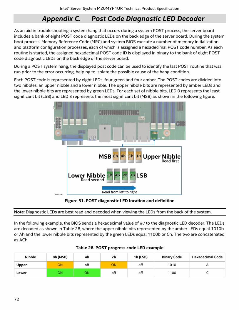
Intel® Server System M20MYP1UR Technical Product Specification
72
Appendix C. Post Code Diagnostic LED Decoder
As an aid in troubleshooting a system hang that occurs during a system POST process, the server board
includes a bank of eight POST code diagnostic LEDs on the back edge of the server board. During the system
boot process, Memory Reference Code (MRC) and system BIOS execute a number of memory initialization
and platform configuration processes, each of which is assigned a hexadecimal POST code number. As each
routine is started, the assigned hexadecimal POST code ID is displayed in binary to the bank of eight POST
code diagnostic LEDs on the back edge of the server board.
During a POST system hang, the displayed post code can be used to identify the last POST routine that was
run prior to the error occurring, helping to isolate the possible cause of the hang condition.
Each POST code is represented by eight LEDs, four green and four amber. The POST codes are divided into
two nibbles, an upper nibble and a lower nibble. The upper nibble bits are represented by amber LEDs and
the lower nibble bits are represented by green LEDs. For each set of nibble bits, LED 0 represents the least
significant bit (LSB) and LED 3 represents the most significant bit (MSB) as shown in the following figure.
Figure 51. POST diagnostic LED location and definition
Note: Diagnostic LEDs are best read and decoded when viewing the LEDs from the back of the system.
In the following example, the BIOS sends a hexadecimal value of AC to the diagnostic LED decoder. The LEDs
are decoded as shown in Table 28, where the upper nibble bits represented by the amber LEDs equal 1010b
or Ah and the lower nibble bits represented by the green LEDs equal 1100b or Ch. The two are concatenated
as ACh.
Table 28. POST progress code LED example
Nibble 8h (MSB) 4h 2h 1h (LSB) Binary Code Hexadecimal Code
Upper ON off ON off 1010 A
Lower ON ON off off 1100 C
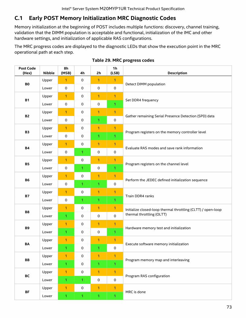
Intel® Server System M20MYP1UR Technical Product Specification
73
C.1 Early POST Memory Initialization MRC Diagnostic Codes
Memory initialization at the beginning of POST includes multiple functions: discovery, channel training,
validation that the DIMM population is acceptable and functional, initialization of the IMC and other
hardware settings, and initialization of applicable RAS configurations.
The MRC progress codes are displayed to the diagnostic LEDs that show the execution point in the MRC
operational path at each step.
Table 29. MRC progress codes
Post Code
(Hex) Nibble
8h
(MSB) 4h 2h
1h
(LSB) Description
B0 Upper 1 0 1 1
Detect DIMM population Lower 0 0 0 0
B1 Upper 1 0 1 1
Set DDR4 frequency Lower 0 0 0 1
B2 Upper 1 0 1 1
Gather remaining Serial Presence Detection (SPD) data Lower 0 0 1 0
B3 Upper 1 0 1 1
Program registers on the memory controller level Lower 0 0 1 1
B4 Upper 1 0 1 1
Evaluate RAS modes and save rank information Lower 0 1 0 0
B5 Upper 1 0 1 1
Program registers on the channel level Lower 0 1 0 1
B6 Upper 1 0 1 1
Perform the JEDEC defined initialization sequence Lower 0 1 1 0
B7 Upper 1 0 1 1
Train DDR4 ranks Lower 0 1 1 1
B8 Upper 1 0 1 1 Initialize closed-loop thermal throttling (CLTT) / open-loop
thermal throttling (OLTT) Lower 1 0 0 0
B9 Upper 1 0 1 1
Hardware memory test and initialization Lower 1 0 0 1
BA Upper 1 0 1 1
Execute software memory initialization Lower 1 0 1 0
BB Upper 1 0 1 1
Program memory map and interleaving Lower 1 0 1 1
BC Upper 1 0 1 1
Program RAS configuration Lower 1 1 0 0
BF Upper 1 0 1 1
MRC is done Lower 1 1 1 1
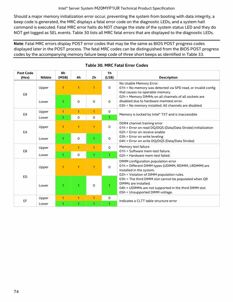
Intel® Server System M20MYP1UR Technical Product Specification
74
Should a major memory initialization error occur, preventing the system from booting with data integrity, a
beep code is generated, the MRC displays a fatal error code on the diagnostic LEDs, and a system halt
command is executed. Fatal MRC error halts do NOT change the state of the system status LED and they do
NOT get logged as SEL events. Table 30 lists all MRC fatal errors that are displayed to the diagnostic LEDs.
Note: Fatal MRC errors display POST error codes that may be the same as BIOS POST progress codes
displayed later in the POST process. The fatal MRC codes can be distinguished from the BIOS POST progress
codes by the accompanying memory failure beep code of three short beeps as identified in Table 33.
Table 30. MRC Fatal Error Codes
Post Code
(Hex) Nibble
8h
(MSB) 4h 2h
1h
(LSB) Description
E8
Upper 1 1 1 0 No Usable Memory Error:
01h = No memory was detected via SPD read, or invalid config
that causes no operable memory.
02h = Memory DIMMs on all channels of all sockets are
disabled due to hardware memtest error.
03h = No memory installed. All channels are disabled. Lower 1 0 0 0
E9 Upper 1 1 1 0
Memory is locked by Intel® TXT and is inaccessible Lower 1 0 0 1
EA
Upper 1 1 1 0 DDR4 channel training error
01h = Error on read DQ/DQS (Data/Data Strobe) initialization
02h = Error on receive enable
03h = Error on write leveling
04h = Error on write DQ/DQS (Data/Data Strobe) Lower 1 0 1 0
EB Upper 1 1 1 0 Memory test failure
01h = Software mem-test failure.
02h = Hardware mem-test failed. Lower 1 0 1 1
ED
Upper 1 1 1 0
DIMM configuration population error
01h = Different DIMM types (UDIMM, RDIMM, LRDIMM) are
installed in the system.
02h = Violation of DIMM population rules.
03h = The third DIMM slot cannot be populated when QR
DIMMs are installed.
04h = UDIMMs are not supported in the third DIMM slot.
05h = Unsupported DIMM voltage.
Lower 1 1 0 1
EF Upper 1 1 1 0
Indicates a CLTT table structure error Lower 1 1 1 1
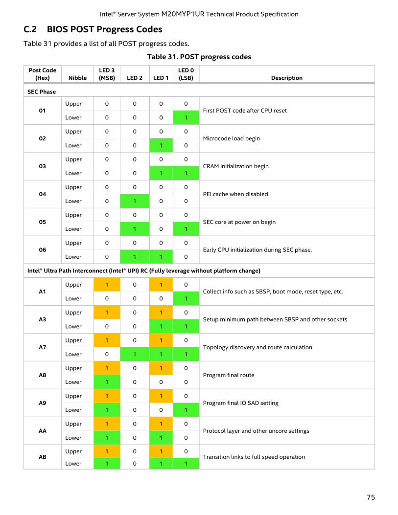
Intel® Server System M20MYP1UR Technical Product Specification
75
C.2 BIOS POST Progress Codes
Table 31 provides a list of all POST progress codes.
Table 31. POST progress codes
Post Code
(Hex) Nibble
LED 3
(MSB) LED 2 LED 1
LED 0
(LSB) Description
SEC Phase
01 Upper 0 0 0 0
First POST code after CPU reset Lower 0 0 0 1
02 Upper 0 0 0 0
Microcode load begin Lower 0 0 1 0
03 Upper 0 0 0 0
CRAM initialization begin Lower 0 0 1 1
04 Upper 0 0 0 0
PEI cache when disabled Lower 0 1 0 0
05 Upper 0 0 0 0
SEC core at power on begin Lower 0 1 0 1
06 Upper 0 0 0 0
Early CPU initialization during SEC phase. Lower 0 1 1 0
Intel® Ultra Path Interconnect (Intel® UPI) RC (Fully leverage without platform change)
A1 Upper 1 0 1 0
Collect info such as SBSP, boot mode, reset type, etc. Lower 0 0 0 1
A3 Upper 1 0 1 0
Setup minimum path between SBSP and other sockets Lower 0 0 1 1
A7 Upper 1 0 1 0
Topology discovery and route calculation Lower 0 1 1 1
A8 Upper 1 0 1 0
Program final route Lower 1 0 0 0
A9 Upper 1 0 1 0
Program final IO SAD setting Lower 1 0 0 1
AA Upper 1 0 1 0
Protocol layer and other uncore settings Lower 1 0 1 0
AB Upper 1 0 1 0
Transition links to full speed operation Lower 1 0 1 1
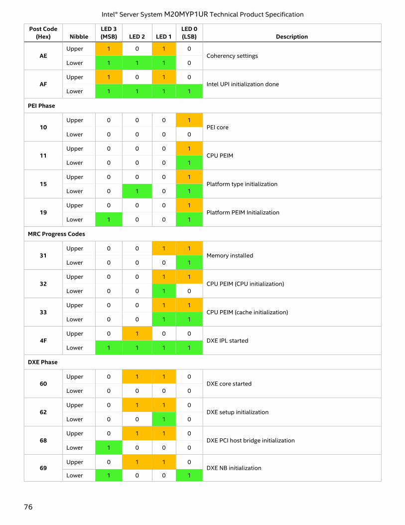
Intel® Server System M20MYP1UR Technical Product Specification
76
Post Code
(Hex) Nibble
LED 3
(MSB) LED 2 LED 1
LED 0
(LSB) Description
AE Upper 1 0 1 0
Coherency settings Lower 1 1 1 0
AF Upper 1 0 1 0
Intel UPI initialization done Lower 1 1 1 1
PEI Phase
10 Upper 0 0 0 1
PEI core Lower 0 0 0 0
11 Upper 0 0 0 1
CPU PEIM Lower 0 0 0 1
15 Upper 0 0 0 1
Platform type initialization Lower 0 1 0 1
19 Upper 0 0 0 1
Platform PEIM Initialization Lower 1 0 0 1
MRC Progress Codes
31 Upper 0 0 1 1
Memory installed Lower 0 0 0 1
32 Upper 0 0 1 1
CPU PEIM (CPU initialization) Lower 0 0 1 0
33 Upper 0 0 1 1
CPU PEIM (cache initialization) Lower 0 0 1 1
4F Upper 0 1 0 0
DXE IPL started Lower 1 1 1 1
DXE Phase
60 Upper 0 1 1 0
DXE core started Lower 0 0 0 0
62 Upper 0 1 1 0
DXE setup initialization Lower 0 0 1 0
68 Upper 0 1 1 0
DXE PCI host bridge initialization Lower 1 0 0 0
69 Upper 0 1 1 0
DXE NB initialization Lower 1 0 0 1
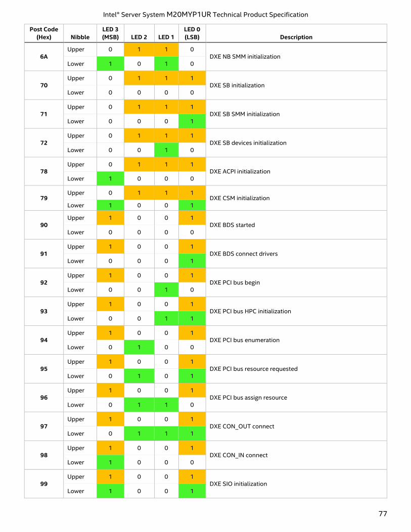
Intel® Server System M20MYP1UR Technical Product Specification
77
Post Code
(Hex) Nibble
LED 3
(MSB) LED 2 LED 1
LED 0
(LSB) Description
6A Upper 0 1 1 0
DXE NB SMM initialization Lower 1 0 1 0
70 Upper 0 1 1 1
DXE SB initialization Lower 0 0 0 0
71 Upper 0 1 1 1
DXE SB SMM initialization Lower 0 0 0 1
72 Upper 0 1 1 1
DXE SB devices initialization Lower 0 0 1 0
78 Upper 0 1 1 1
DXE ACPI initialization Lower 1 0 0 0
79 Upper 0 1 1 1
DXE CSM initialization Lower 1 0 0 1
90 Upper 1 0 0 1
DXE BDS started Lower 0 0 0 0
91 Upper 1 0 0 1
DXE BDS connect drivers Lower 0 0 0 1
92 Upper 1 0 0 1
DXE PCI bus begin Lower 0 0 1 0
93 Upper 1 0 0 1
DXE PCI bus HPC initialization Lower 0 0 1 1
94 Upper 1 0 0 1
DXE PCI bus enumeration Lower 0 1 0 0
95 Upper 1 0 0 1
DXE PCI bus resource requested Lower 0 1 0 1
96 Upper 1 0 0 1
DXE PCI bus assign resource Lower 0 1 1 0
97 Upper 1 0 0 1
DXE CON_OUT connect Lower 0 1 1 1
98 Upper 1 0 0 1
DXE CON_IN connect Lower 1 0 0 0
99 Upper 1 0 0 1
DXE SIO initialization Lower 1 0 0 1
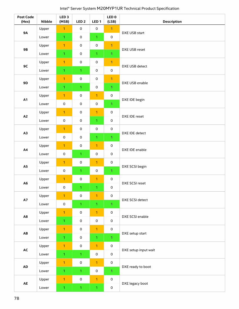
Intel® Server System M20MYP1UR Technical Product Specification
78
Post Code
(Hex) Nibble
LED 3
(MSB) LED 2 LED 1
LED 0
(LSB) Description
9A Upper 1 0 0 1
DXE USB start Lower 1 0 1 0
9B Upper 1 0 0 1
DXE USB reset Lower 1 0 1 1
9C Upper 1 0 0 1
DXE USB detect Lower 1 1 0 0
9D Upper 1 0 0 1
DXE USB enable Lower 1 1 0 1
A1 Upper 1 0 1 0
DXE IDE begin Lower 0 0 0 1
A2 Upper 1 0 1 0
DXE IDE reset Lower 0 0 1 0
A3 Upper 1 0 0 0
DXE IDE detect Lower 0 0 1 1
A4 Upper 1 0 1 0
DXE IDE enable Lower 0 1 0 0
A5 Upper 1 0 1 0
DXE SCSI begin Lower 0 1 0 1
A6 Upper 1 0 1 0
DXE SCSI reset Lower 0 1 1 0
A7 Upper 1 0 1 0
DXE SCSI detect Lower 0 1 1 1
A8 Upper 1 0 1 0
DXE SCSI enable Lower 1 0 0 0
AB Upper 1 0 1 0
DXE setup start Lower 1 0 1 1
AC Upper 1 0 1 0
DXE setup input wait Lower 1 1 0 0
AD Upper 1 0 1 0
DXE ready to boot Lower 1 1 0 1
AE Upper 1 0 1 0
DXE legacy boot Lower 1 1 1 0
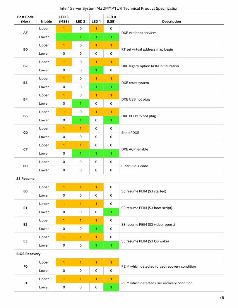
Intel® Server System M20MYP1UR Technical Product Specification
79
Post Code
(Hex) Nibble
LED 3
(MSB) LED 2 LED 1
LED 0
(LSB) Description
AF Upper 1 0 1 0
DXE exit boot services Lower 1 1 1 1
B0 Upper 1 0 1 1
RT set virtual address map begin Lower 0 0 0 0
B2 Upper 1 0 1 1
DXE legacy option ROM initialization Lower 0 0 1 0
B3 Upper 1 0 1 1
DXE reset system Lower 0 0 1 1
B4 Upper 1 0 1 1
DXE USB hot plug Lower 0 1 0 0
B5 Upper 1 0 1 1
DXE PCI BUS hot plug Lower 0 1 0 1
C0 Upper 1 1 0 0
End of DXE Lower 0 0 0 0
C7 Upper 1 1 0 0
DXE ACPI enable Lower 0 1 1 1
00 Upper 0 0 0 0
Clear POST code Lower 0 0 0 0
S3 Resume
E0 Upper 1 1 1 0
S3 resume PEIM (S3 started) Lower 0 0 0 0
E1 Upper 1 1 1 0
S3 resume PEIM (S3 boot script) Lower 0 0 0 1
E2 Upper 1 1 1 0
S3 resume PEIM (S3 video repost) Lower 0 0 1 0
E3 Upper 1 1 1 0
S3 resume PEIM (S3 OS wake) Lower 0 0 1 1
BIOS Recovery
F0 Upper 1 1 1 1
PEIM which detected forced recovery condition Lower 0 0 0 0
F1 Upper 1 1 1 1
PEIM which detected user recovery condition Lower 0 0 0 1
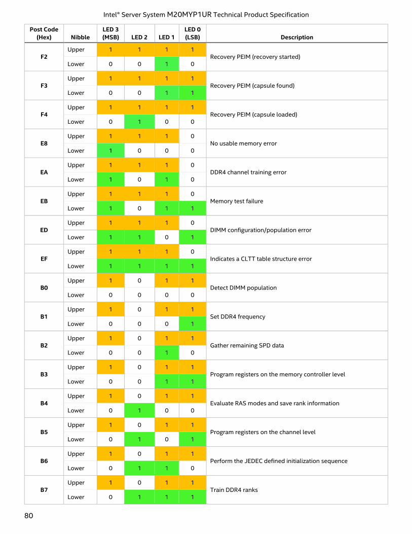
Intel® Server System M20MYP1UR Technical Product Specification
80
Post Code
(Hex) Nibble
LED 3
(MSB) LED 2 LED 1
LED 0
(LSB) Description
F2 Upper 1 1 1 1
Recovery PEIM (recovery started) Lower 0 0 1 0
F3 Upper 1 1 1 1
Recovery PEIM (capsule found) Lower 0 0 1 1
F4 Upper 1 1 1 1
Recovery PEIM (capsule loaded) Lower 0 1 0 0
E8 Upper 1 1 1 0
No usable memory error Lower 1 0 0 0
EA Upper 1 1 1 0
DDR4 channel training error Lower 1 0 1 0
EB Upper 1 1 1 0
Memory test failure Lower 1 0 1 1
ED Upper 1 1 1 0
DIMM configuration/population error Lower 1 1 0 1
EF Upper 1 1 1 0
Indicates a CLTT table structure error Lower 1 1 1 1
B0 Upper 1 0 1 1
Detect DIMM population Lower 0 0 0 0
B1 Upper 1 0 1 1
Set DDR4 frequency Lower 0 0 0 1
B2 Upper 1 0 1 1
Gather remaining SPD data Lower 0 0 1 0
B3 Upper 1 0 1 1
Program registers on the memory controller level Lower 0 0 1 1
B4 Upper 1 0 1 1
Evaluate RAS modes and save rank information Lower 0 1 0 0
B5 Upper 1 0 1 1
Program registers on the channel level Lower 0 1 0 1
B6 Upper 1 0 1 1
Perform the JEDEC defined initialization sequence Lower 0 1 1 0
B7 Upper 1 0 1 1
Train DDR4 ranks Lower 0 1 1 1
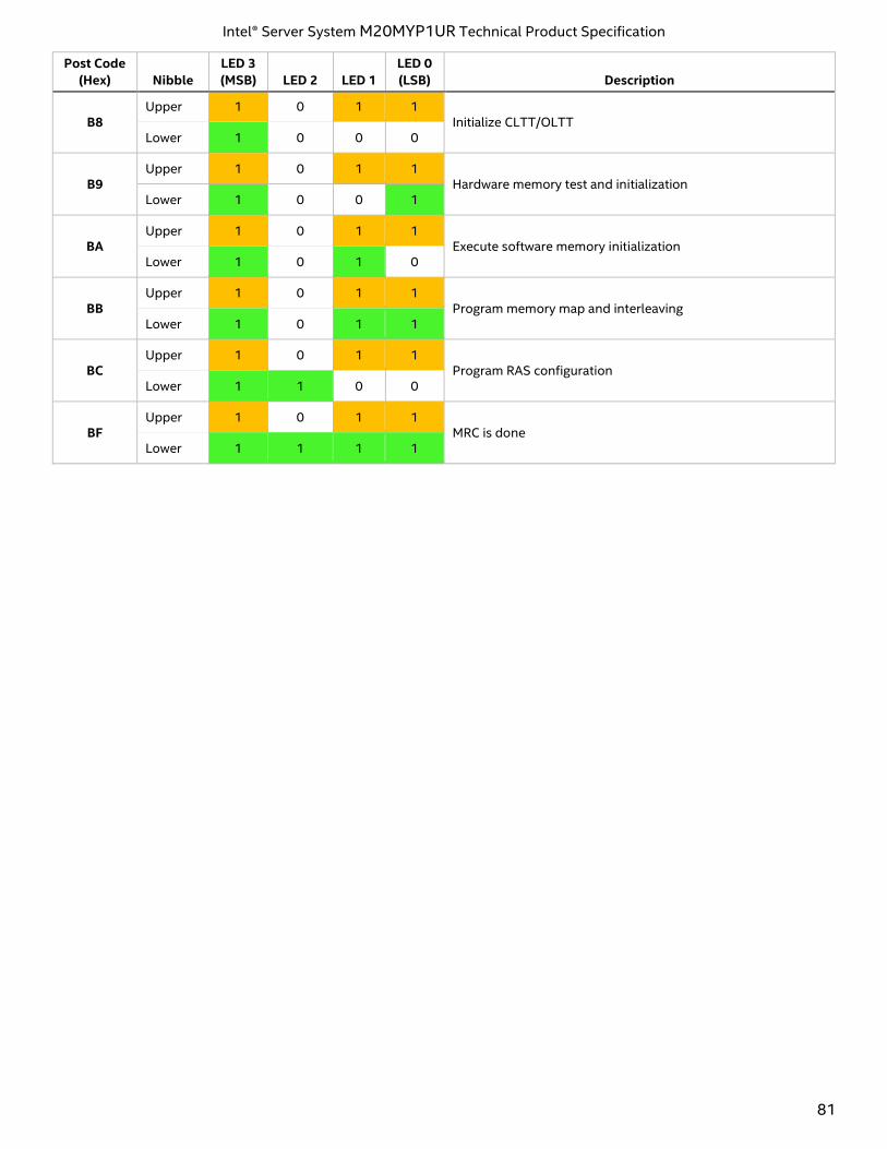
Intel® Server System M20MYP1UR Technical Product Specification
81
Post Code
(Hex) Nibble
LED 3
(MSB) LED 2 LED 1
LED 0
(LSB) Description
B8 Upper 1 0 1 1
Initialize CLTT/OLTT Lower 1 0 0 0
B9 Upper 1 0 1 1
Hardware memory test and initialization Lower 1 0 0 1
BA Upper 1 0 1 1
Execute software memory initialization Lower 1 0 1 0
BB Upper 1 0 1 1
Program memory map and interleaving Lower 1 0 1 1
BC Upper 1 0 1 1
Program RAS configuration Lower 1 1 0 0
BF Upper 1 0 1 1
MRC is done Lower 1 1 1 1
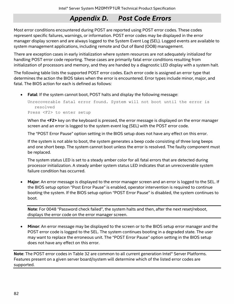
Intel® Server System M20MYP1UR Technical Product Specification
82
Appendix D. Post Code Errors
Most error conditions encountered during POST are reported using POST error codes. These codes
represent specific failures, warnings, or information. POST error codes may be displayed in the error
manager display screen and are always logged to the System Event Log (SEL). Logged events are available to
system management applications, including remote and Out of Band (OOB) management.
There are exception cases in early initialization where system resources are not adequately initialized for
handling POST error code reporting. These cases are primarily fatal error conditions resulting from
initialization of processors and memory, and they are handed by a diagnostic LED display with a system halt.
The following table lists the supported POST error codes. Each error code is assigned an error type that
determines the action the BIOS takes when the error is encountered. Error types include minor, major, and
fatal. The BIOS action for each is defined as follows:
• Fatal: If the system cannot boot, POST halts and display the following message:
Unrecoverable fatal error found. System will not boot until the error is
resolved
Press <F2> to enter setup
When the <F2> key on the keyboard is pressed, the error message is displayed on the error manager
screen and an error is logged to the system event log (SEL) with the POST error code.
The “POST Error Pause” option setting in the BIOS setup does not have any effect on this error.
If the system is not able to boot, the system generates a beep code consisting of three long beeps
and one short beep. The system cannot boot unless the error is resolved. The faulty component must
be replaced.
The system status LED is set to a steady amber color for all fatal errors that are detected during
processor initialization. A steady amber system status LED indicates that an unrecoverable system
failure condition has occurred.
• Major: An error message is displayed to the error manager screen and an error is logged to the SEL. If
the BIOS setup option “Post Error Pause” is enabled, operator intervention is required to continue
booting the system. If the BIOS setup option “POST Error Pause” is disabled, the system continues to
boot.
Note: For 0048 “Password check failed”, the system halts and then, after the next reset/reboot,
displays the error code on the error manager screen.
• Minor: An error message may be displayed to the screen or to the BIOS setup error manager and the
POST error code is logged to the SEL. The system continues booting in a degraded state. The user
may want to replace the erroneous unit. The “POST Error Pause” option setting in the BIOS setup
does not have any effect on this error.
Note: The POST error codes in Table 32 are common to all current generation Intel® Server Platforms.
Features present on a given server board/system will determine which of the listed error codes are
supported.
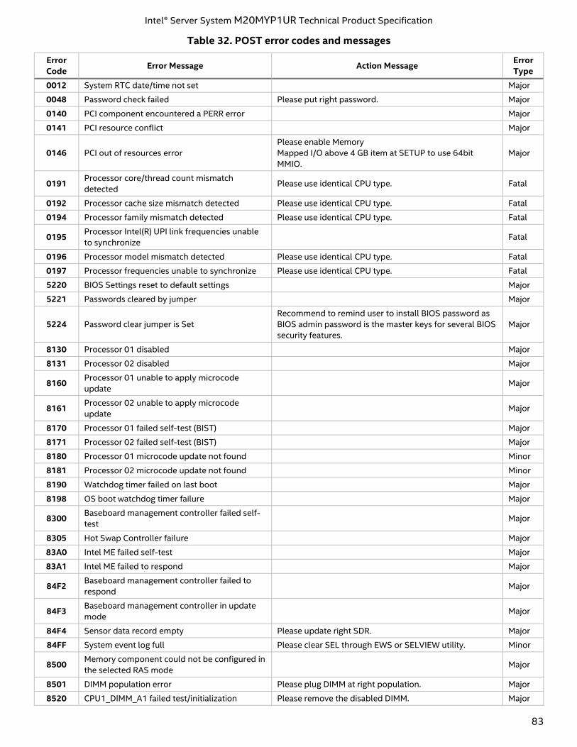
Intel® Server System M20MYP1UR Technical Product Specification
83
Table 32. POST error codes and messages
Error
Code Error Message Action Message
Error
Type
0012 System RTC date/time not set Major
0048 Password check failed Please put right password. Major
0140 PCI component encountered a PERR error Major
0141 PCI resource conflict Major
0146 PCI out of resources error
Please enable Memory
Mapped I/O above 4 GB item at SETUP to use 64bit
MMIO.
Major
0191 Processor core/thread count mismatch
detected Please use identical CPU type. Fatal
0192 Processor cache size mismatch detected Please use identical CPU type. Fatal
0194 Processor family mismatch detected Please use identical CPU type. Fatal
0195 Processor Intel(R) UPI link frequencies unable
to synchronize Fatal
0196 Processor model mismatch detected Please use identical CPU type. Fatal
0197 Processor frequencies unable to synchronize Please use identical CPU type. Fatal
5220 BIOS Settings reset to default settings Major
5221 Passwords cleared by jumper Major
5224 Password clear jumper is Set
Recommend to remind user to install BIOS password as
BIOS admin password is the master keys for several BIOS
security features.
Major
8130 Processor 01 disabled Major
8131 Processor 02 disabled Major
8160 Processor 01 unable to apply microcode
update Major
8161 Processor 02 unable to apply microcode
update Major
8170 Processor 01 failed self-test (BIST) Major
8171 Processor 02 failed self-test (BIST) Major
8180 Processor 01 microcode update not found Minor
8181 Processor 02 microcode update not found Minor
8190 Watchdog timer failed on last boot Major
8198 OS boot watchdog timer failure Major
8300 Baseboard management controller failed self-
test Major
8305 Hot Swap Controller failure Major
83A0 Intel ME failed self-test Major
83A1 Intel ME failed to respond Major
84F2 Baseboard management controller failed to
respond Major
84F3 Baseboard management controller in update
mode Major
84F4 Sensor data record empty Please update right SDR. Major
84FF System event log full Please clear SEL through EWS or SELVIEW utility. Minor
8500 Memory component could not be configured in
the selected RAS mode Major
8501 DIMM population error Please plug DIMM at right population. Major
8520 CPU1_DIMM_A1 failed test/initialization Please remove the disabled DIMM. Major
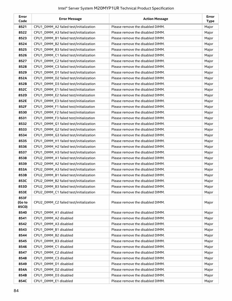
Intel® Server System M20MYP1UR Technical Product Specification
84
Error
Code Error Message Action Message
Error
Type
8521 CPU1_DIMM_A2 failed test/initialization Please remove the disabled DIMM. Major
8522 CPU1_DIMM_A3 failed test/initialization Please remove the disabled DIMM. Major
8523 CPU1_DIMM_B1 failed test/initialization Please remove the disabled DIMM. Major
8524 CPU1_DIMM_B2 failed test/initialization Please remove the disabled DIMM. Major
8525 CPU1_DIMM_B3 failed test/initialization Please remove the disabled DIMM. Major
8526 CPU1_DIMM_C1 failed test/initialization Please remove the disabled DIMM. Major
8527 CPU1_DIMM_C2 failed test/initialization Please remove the disabled DIMM. Major
8528 CPU1_DIMM_C3 failed test/initialization Please remove the disabled DIMM. Major
8529 CPU1_DIMM_D1 failed test/initialization Please remove the disabled DIMM. Major
852A CPU1_DIMM_D2 failed test/initialization Please remove the disabled DIMM. Major
852B CPU1_DIMM_D3 failed test/initialization Please remove the disabled DIMM. Major
852C CPU1_DIMM_E1 failed test/initialization Please remove the disabled DIMM. Major
852D CPU1_DIMM_E2 failed test/initialization Please remove the disabled DIMM. Major
852E CPU1_DIMM_E3 failed test/initialization Please remove the disabled DIMM. Major
852F CPU1_DIMM_F1 failed test/initialization Please remove the disabled DIMM. Major
8530 CPU1_DIMM_F2 failed test/initialization Please remove the disabled DIMM. Major
8531 CPU1_DIMM_F3 failed test/initialization Please remove the disabled DIMM. Major
8532 CPU1_DIMM_G1 failed test/initialization Please remove the disabled DIMM. Major
8533 CPU1_DIMM_G2 failed test/initialization Please remove the disabled DIMM. Major
8534 CPU1_DIMM_G3 failed test/initialization Please remove the disabled DIMM. Major
8535 CPU1_DIMM_H1 failed test/initialization Please remove the disabled DIMM. Major
8536 CPU1_DIMM_H2 failed test/initialization Please remove the disabled DIMM. Major
8537 CPU1_DIMM_H3 failed test/initialization Please remove the disabled DIMM. Major
8538 CPU2_DIMM_A1 failed test/initialization Please remove the disabled DIMM. Major
8539 CPU2_DIMM_A2 failed test/initialization Please remove the disabled DIMM. Major
853A CPU2_DIMM_A3 failed test/initialization Please remove the disabled DIMM. Major
853B CPU2_DIMM_B1 failed test/initialization Please remove the disabled DIMM. Major
853C CPU2_DIMM_B2 failed test/initialization Please remove the disabled DIMM. Major
853D CPU2_DIMM_B3 failed test/initialization Please remove the disabled DIMM. Major
853E CPU2_DIMM_C1 failed test/initialization Please remove the disabled DIMM. Major
853F
(Go to
85C0)
CPU2_DIMM_C2 failed test/initialization Please remove the disabled DIMM. Major
8540 CPU1_DIMM_A1 disabled Please remove the disabled DIMM. Major
8541 CPU1_DIMM_A2 disabled Please remove the disabled DIMM. Major
8542 CPU1_DIMM_A3 disabled Please remove the disabled DIMM. Major
8543 CPU1_DIMM_B1 disabled Please remove the disabled DIMM. Major
8544 CPU1_DIMM_B2 disabled Please remove the disabled DIMM. Major
8545 CPU1_DIMM_B3 disabled Please remove the disabled DIMM. Major
8546 CPU1_DIMM_C1 disabled Please remove the disabled DIMM. Major
8547 CPU1_DIMM_C2 disabled Please remove the disabled DIMM. Major
8548 CPU1_DIMM_C3 disabled Please remove the disabled DIMM. Major
8549 CPU1_DIMM_D1 disabled Please remove the disabled DIMM. Major
854A CPU1_DIMM_D2 disabled Please remove the disabled DIMM. Major
854B CPU1_DIMM_D3 disabled Please remove the disabled DIMM. Major
854C CPU1_DIMM_E1 disabled Please remove the disabled DIMM. Major
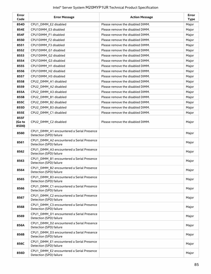
Intel® Server System M20MYP1UR Technical Product Specification
85
Error
Code Error Message Action Message
Error
Type
854D CPU1_DIMM_E2 disabled Please remove the disabled DIMM. Major
854E CPU1DIMM_E3 disabled Please remove the disabled DIMM. Major
854F CPU1DIMM_F1 disabled Please remove the disabled DIMM. Major
8550 CPU1DIMM_F2 disabled Please remove the disabled DIMM. Major
8551 CPU1DIMM_F3 disabled Please remove the disabled DIMM. Major
8552 CPU1DIMM_G1 disabled Please remove the disabled DIMM. Major
8553 CPU1DIMM_G2 disabled Please remove the disabled DIMM. Major
8554 CPU1DIMM_G3 disabled Please remove the disabled DIMM. Major
8555 CPU1DIMM_H1 disabled Please remove the disabled DIMM. Major
8556 CPU1DIMM_H2 disabled Please remove the disabled DIMM. Major
8557 CPU1DIMM_H3 disabled Please remove the disabled DIMM. Major
8558 CPU2_DIMM_A1 disabled Please remove the disabled DIMM. Major
8559 CPU2_DIMM_A2 disabled Please remove the disabled DIMM. Major
855A CPU2_DIMM_A3 disabled Please remove the disabled DIMM. Major
855B CPU2_DIMM_B1 disabled Please remove the disabled DIMM. Major
855C CPU2_DIMM_B2 disabled Please remove the disabled DIMM. Major
855D CPU2_DIMM_B3 disabled Please remove the disabled DIMM. Major
855E CPU2_DIMM_C1 disabled Please remove the disabled DIMM. Major
855F
(Go to
85D0)
CPU2_DIMM_C2 disabled Please remove the disabled DIMM. Major
8560 CPU1_DIMM_A1 encountered a Serial Presence
Detection (SPD) failure Major
8561 CPU1_DIMM_A2 encountered a Serial Presence
Detection (SPD) failure Major
8562 CPU1_DIMM_A3 encountered a Serial Presence
Detection (SPD) failure Major
8563 CPU1_DIMM_B1 encountered a Serial Presence
Detection (SPD) failure Major
8564 CPU1_DIMM_B2 encountered a Serial Presence
Detection (SPD) failure Major
8565 CPU1_DIMM_B3 encountered a Serial Presence
Detection (SPD) failure Major
8566 CPU1_DIMM_C1 encountered a Serial Presence
Detection (SPD) failure Major
8567 CPU1_DIMM_C2 encountered a Serial Presence
Detection (SPD) failure Major
8568 CPU1_DIMM_C3 encountered a Serial Presence
Detection (SPD) failure Major
8569 CPU1_DIMM_D1 encountered a Serial Presence
Detection (SPD) failure Major
856A CPU1_DIMM_D2 encountered a Serial Presence
Detection (SPD) failure Major
856B CPU1_DIMM_D3 encountered a Serial Presence
Detection (SPD) failure Major
856C CPU1_DIMM_E1 encountered a Serial Presence
Detection (SPD) failure Major
856D CPU1_DIMM_E2 encountered a Serial Presence
Detection (SPD) failure Major
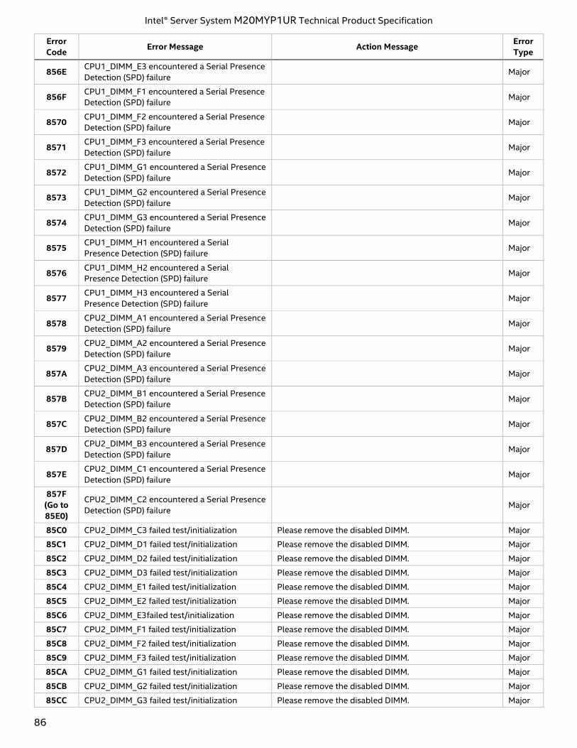
Intel® Server System M20MYP1UR Technical Product Specification
86
Error
Code Error Message Action Message
Error
Type
856E CPU1_DIMM_E3 encountered a Serial Presence
Detection (SPD) failure Major
856F CPU1_DIMM_F1 encountered a Serial Presence
Detection (SPD) failure Major
8570 CPU1_DIMM_F2 encountered a Serial Presence
Detection (SPD) failure Major
8571 CPU1_DIMM_F3 encountered a Serial Presence
Detection (SPD) failure Major
8572 CPU1_DIMM_G1 encountered a Serial Presence
Detection (SPD) failure Major
8573 CPU1_DIMM_G2 encountered a Serial Presence
Detection (SPD) failure Major
8574 CPU1_DIMM_G3 encountered a Serial Presence
Detection (SPD) failure Major
8575 CPU1_DIMM_H1 encountered a Serial
Presence Detection (SPD) failure Major
8576 CPU1_DIMM_H2 encountered a Serial
Presence Detection (SPD) failure Major
8577 CPU1_DIMM_H3 encountered a Serial
Presence Detection (SPD) failure Major
8578 CPU2_DIMM_A1 encountered a Serial Presence
Detection (SPD) failure Major
8579 CPU2_DIMM_A2 encountered a Serial Presence
Detection (SPD) failure Major
857A CPU2_DIMM_A3 encountered a Serial Presence
Detection (SPD) failure Major
857B CPU2_DIMM_B1 encountered a Serial Presence
Detection (SPD) failure Major
857C CPU2_DIMM_B2 encountered a Serial Presence
Detection (SPD) failure Major
857D CPU2_DIMM_B3 encountered a Serial Presence
Detection (SPD) failure Major
857E CPU2_DIMM_C1 encountered a Serial Presence
Detection (SPD) failure Major
857F
(Go to
85E0)
CPU2_DIMM_C2 encountered a Serial Presence
Detection (SPD) failure Major
85C0 CPU2_DIMM_C3 failed test/initialization Please remove the disabled DIMM. Major
85C1 CPU2_DIMM_D1 failed test/initialization Please remove the disabled DIMM. Major
85C2 CPU2_DIMM_D2 failed test/initialization Please remove the disabled DIMM. Major
85C3 CPU2_DIMM_D3 failed test/initialization Please remove the disabled DIMM. Major
85C4 CPU2_DIMM_E1 failed test/initialization Please remove the disabled DIMM. Major
85C5 CPU2_DIMM_E2 failed test/initialization Please remove the disabled DIMM. Major
85C6 CPU2_DIMM_E3failed test/initialization Please remove the disabled DIMM. Major
85C7 CPU2_DIMM_F1 failed test/initialization Please remove the disabled DIMM. Major
85C8 CPU2_DIMM_F2 failed test/initialization Please remove the disabled DIMM. Major
85C9 CPU2_DIMM_F3 failed test/initialization Please remove the disabled DIMM. Major
85CA CPU2_DIMM_G1 failed test/initialization Please remove the disabled DIMM. Major
85CB CPU2_DIMM_G2 failed test/initialization Please remove the disabled DIMM. Major
85CC CPU2_DIMM_G3 failed test/initialization Please remove the disabled DIMM. Major
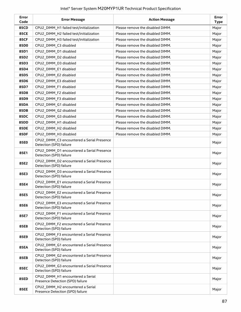
Intel® Server System M20MYP1UR Technical Product Specification
87
Error
Code Error Message Action Message
Error
Type
85CD CPU2_DIMM_H1 failed test/initialization Please remove the disabled DIMM. Major
85CE CPU2_DIMM_H2 failed test/initialization Please remove the disabled DIMM. Major
85CF CPU2_DIMM_H3 failed test/initialization Please remove the disabled DIMM. Major
85D0 CPU2_DIMM_C3 disabled Please remove the disabled DIMM. Major
85D1 CPU2_DIMM_D1 disabled Please remove the disabled DIMM. Major
85D2 CPU2_DIMM_D2 disabled Please remove the disabled DIMM. Major
85D3 CPU2_DIMM_D3 disabled Please remove the disabled DIMM. Major
85D4 CPU2_DIMM_E1 disabled Please remove the disabled DIMM. Major
85D5 CPU2_DIMM_E2 disabled Please remove the disabled DIMM. Major
85D6 CPU2_DIMM_E3 disabled Please remove the disabled DIMM. Major
85D7 CPU2_DIMM_F1 disabled Please remove the disabled DIMM. Major
85D8 CPU2_DIMM_F2 disabled Please remove the disabled DIMM. Major
85D9 CPU2_DIMM_F3 disabled Please remove the disabled DIMM. Major
85DA CPU2_DIMM_G1 disabled Please remove the disabled DIMM. Major
85DB CPU2_DIMM_G2 disabled Please remove the disabled DIMM. Major
85DC CPU2_DIMM_G3 disabled Please remove the disabled DIMM. Major
85DD CPU2_DIMM_H1 disabled Please remove the disabled DIMM. Major
85DE CPU2_DIMM_H2 disabled Please remove the disabled DIMM. Major
85DF CPU2_DIMM_H3 disabled Please remove the disabled DIMM. Major
85E0 CPU2_DIMM_C3 encountered a Serial Presence
Detection (SPD) failure Major
85E1 CPU2_DIMM_D1 encountered a Serial Presence
Detection (SPD) failure Major
85E2 CPU2_DIMM_D2 encountered a Serial Presence
Detection (SPD) failure Major
85E3 CPU2_DIMM_D3 encountered a Serial Presence
Detection (SPD) failure Major
85E4 CPU2_DIMM_E1 encountered a Serial Presence
Detection (SPD) failure Major
85E5 CPU2_DIMM_E2 encountered a Serial Presence
Detection (SPD) failure Major
85E6 CPU2_DIMM_E3 encountered a Serial Presence
Detection (SPD) failure Major
85E7 CPU2_DIMM_F1 encountered a Serial Presence
Detection (SPD) failure Major
85E8 CPU2_DIMM_F2 encountered a Serial Presence
Detection (SPD) failure Major
85E9 CPU2_DIMM_F3 encountered a Serial Presence
Detection (SPD) failure Major
85EA CPU2_DIMM_G1 encountered a Serial Presence
Detection (SPD) failure Major
85EB CPU2_DIMM_G2 encountered a Serial Presence
Detection (SPD) failure Major
85EC CPU2_DIMM_G3 encountered a Serial Presence
Detection (SPD) failure Major
85ED CPU2_DIMM_H1 encountered a Serial
Presence Detection (SPD) failure Major
85EE CPU2_DIMM_H2 encountered a Serial
Presence Detection (SPD) failure Major
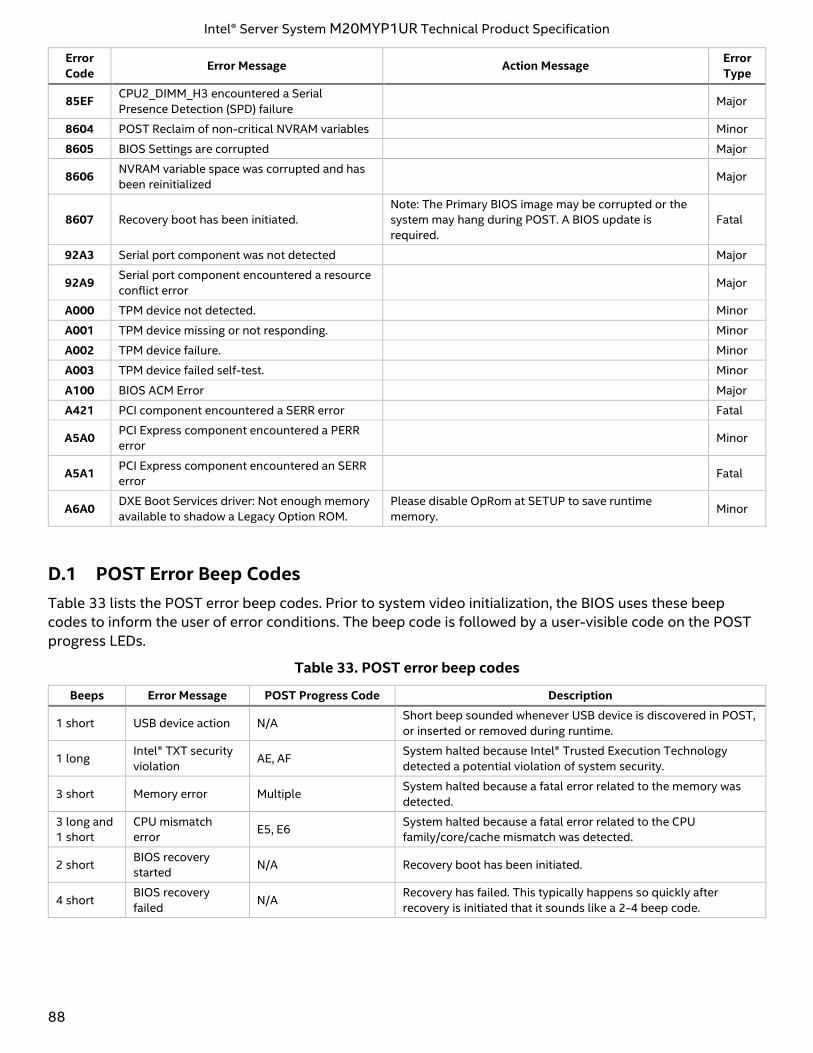
Intel® Server System M20MYP1UR Technical Product Specification
88
Error
Code Error Message Action Message
Error
Type
85EF CPU2_DIMM_H3 encountered a Serial
Presence Detection (SPD) failure Major
8604 POST Reclaim of non-critical NVRAM variables Minor
8605 BIOS Settings are corrupted Major
8606 NVRAM variable space was corrupted and has
been reinitialized Major
8607 Recovery boot has been initiated.
Note: The Primary BIOS image may be corrupted or the
system may hang during POST. A BIOS update is
required.
Fatal
92A3 Serial port component was not detected Major
92A9 Serial port component encountered a resource
conflict error Major
A000 TPM device not detected. Minor
A001 TPM device missing or not responding. Minor
A002 TPM device failure. Minor
A003 TPM device failed self-test. Minor
A100 BIOS ACM Error Major
A421 PCI component encountered a SERR error Fatal
A5A0 PCI Express component encountered a PERR
error Minor
A5A1 PCI Express component encountered an SERR
error Fatal
A6A0 DXE Boot Services driver: Not enough memory
available to shadow a Legacy Option ROM.
Please disable OpRom at SETUP to save runtime
memory. Minor
D.1 POST Error Beep Codes
Table 33 lists the POST error beep codes. Prior to system video initialization, the BIOS uses these beep
codes to inform the user of error conditions. The beep code is followed by a user-visible code on the POST
progress LEDs.
Table 33. POST error beep codes
Beeps Error Message POST Progress Code Description
1 short USB device action N/A Short beep sounded whenever USB device is discovered in POST,
or inserted or removed during runtime.
1 long Intel® TXT security
violation AE, AF
System halted because Intel® Trusted Execution Technology
detected a potential violation of system security.
3 short Memory error Multiple System halted because a fatal error related to the memory was
detected.
3 long and
1 short
CPU mismatch
error E5, E6
System halted because a fatal error related to the CPU
family/core/cache mismatch was detected.
2 short BIOS recovery
started N/A Recovery boot has been initiated.
4 short BIOS recovery
failed N/A
Recovery has failed. This typically happens so quickly after
recovery is initiated that it sounds like a 2-4 beep code.
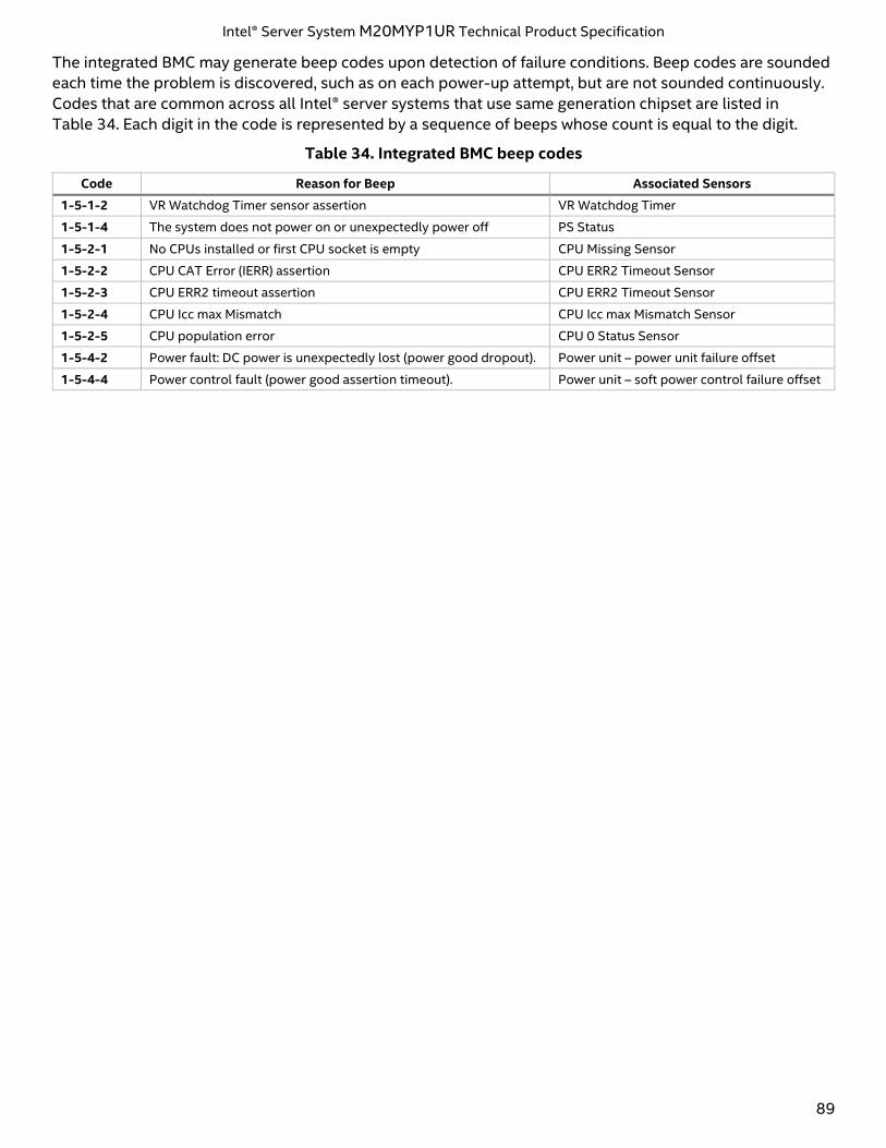
Intel® Server System M20MYP1UR Technical Product Specification
89
The integrated BMC may generate beep codes upon detection of failure conditions. Beep codes are sounded
each time the problem is discovered, such as on each power-up attempt, but are not sounded continuously.
Codes that are common across all Intel® server systems that use same generation chipset are listed in
Table 34. Each digit in the code is represented by a sequence of beeps whose count is equal to the digit.
Table 34. Integrated BMC beep codes
Code Reason for Beep Associated Sensors
1-5-1-2 VR Watchdog Timer sensor assertion VR Watchdog Timer
1-5-1-4 The system does not power on or unexpectedly power off PS Status
1-5-2-1 No CPUs installed or first CPU socket is empty CPU Missing Sensor
1-5-2-2 CPU CAT Error (IERR) assertion CPU ERR2 Timeout Sensor
1-5-2-3 CPU ERR2 timeout assertion CPU ERR2 Timeout Sensor
1-5-2-4 CPU Icc max Mismatch CPU Icc max Mismatch Sensor
1-5-2-5 CPU population error CPU 0 Status Sensor
1-5-4-2 Power fault: DC power is unexpectedly lost (power good dropout). Power unit – power unit failure offset
1-5-4-4 Power control fault (power good assertion timeout). Power unit – soft power control failure offset
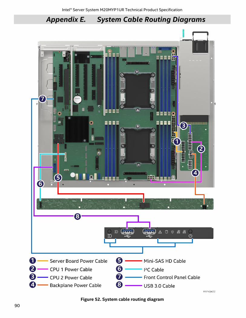
Intel® Server System M20MYP1UR Technical Product Specification
90
Appendix E. System Cable Routing Diagrams
Figure 52. System cable routing diagram
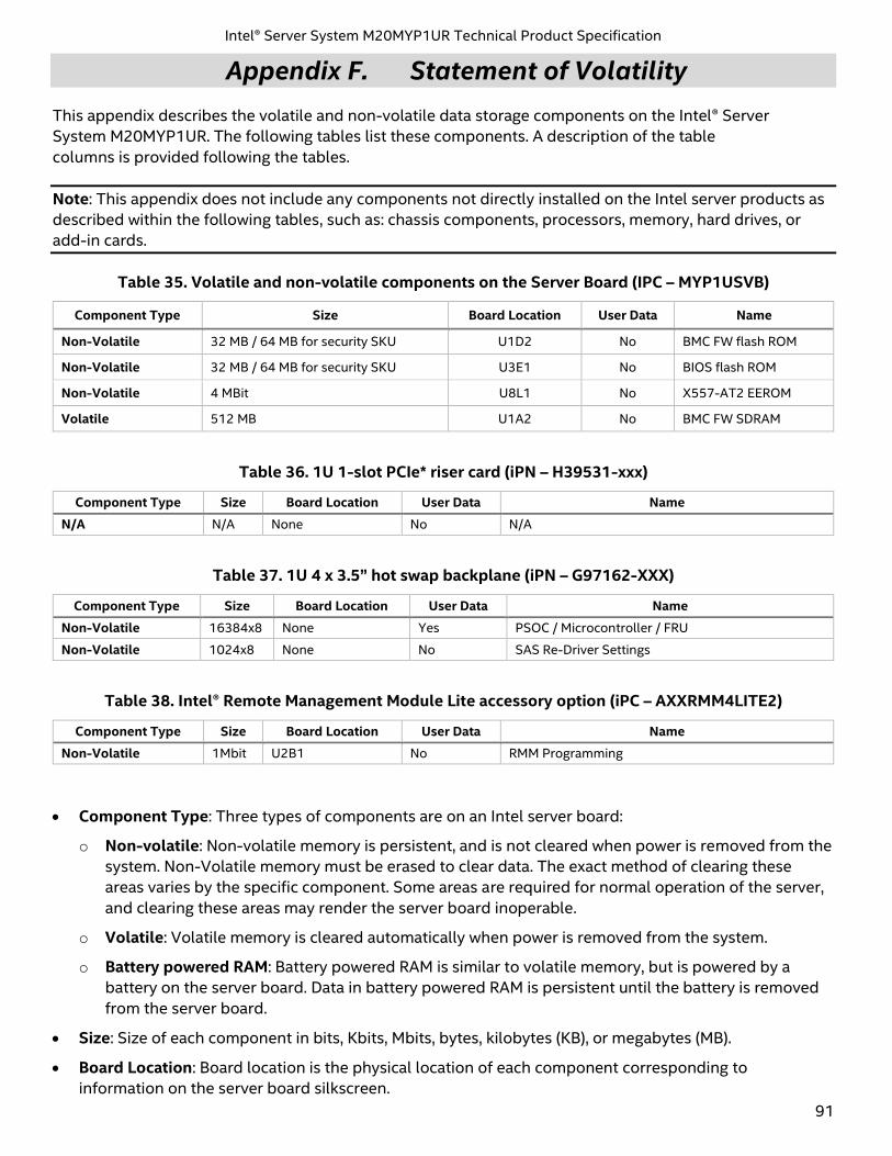
Intel® Server System M20MYP1UR Technical Product Specification
91
Appendix F. Statement of Volatility
This appendix describes the volatile and non-volatile data storage components on the Intel® Server
System M20MYP1UR. The following tables list these components. A description of the table
columns is provided following the tables.
Note: This appendix does not include any components not directly installed on the Intel server products as
described within the following tables, such as: chassis components, processors, memory, hard drives, or
add-in cards.
Table 35. Volatile and non-volatile components on the Server Board (IPC – MYP1USVB)
Component Type Size Board Location User Data Name
Non-Volatile 32 MB / 64 MB for security SKU U1D2 No BMC FW flash ROM
Non-Volatile 32 MB / 64 MB for security SKU U3E1 No BIOS flash ROM
Non-Volatile 4 MBit U8L1 No X557-AT2 EEROM
Volatile 512 MB U1A2 No BMC FW SDRAM
Table 36. 1U 1-slot PCIe* riser card (iPN – H39531-xxx)
Component Type Size Board Location User Data Name
N/A N/A None No N/A
Table 37. 1U 4 x 3.5” hot swap backplane (iPN – G97162-XXX)
Component Type Size Board Location User Data Name
Non-Volatile 16384x8 None Yes PSOC / Microcontroller / FRU
Non-Volatile 1024x8 None No SAS Re-Driver Settings
Table 38. Intel® Remote Management Module Lite accessory option (iPC – AXXRMM4LITE2)
Component Type Size Board Location User Data Name
Non-Volatile 1Mbit U2B1 No RMM Programming
• Component Type: Three types of components are on an Intel server board:
o Non-volatile: Non-volatile memory is persistent, and is not cleared when power is removed from the
system. Non-Volatile memory must be erased to clear data. The exact method of clearing these
areas varies by the specific component. Some areas are required for normal operation of the server,
and clearing these areas may render the server board inoperable.
o Volatile: Volatile memory is cleared automatically when power is removed from the system.
o Battery powered RAM: Battery powered RAM is similar to volatile memory, but is powered by a
battery on the server board. Data in battery powered RAM is persistent until the battery is removed
from the server board.
• Size: Size of each component in bits, Kbits, Mbits, bytes, kilobytes (KB), or megabytes (MB).
• Board Location: Board location is the physical location of each component corresponding to
information on the server board silkscreen.
Intel® Server System M20MYP1UR Technical Product Specification
92
• User Data: The flash components on the server board do not store user data from the operating system.
No operating system level data is retained in any listed components after AC power is removed. The
persistence of information written to each component is determined by its type as described in the
table.
Each component stores data specific to its function. Some components may contain passwords that
provide access to that device’s configuration or functionality. These passwords are specific to the device
and are unique and unrelated to operating system passwords. The specific components that may
contain password data are:
o BIOS: The server board BIOS provides the capability to prevent unauthorized users from configuring
BIOS settings when a BIOS password is set. This password is stored in BIOS flash, and is only used to
set BIOS configuration access restrictions.
o BMC: The server boards support an Intelligent Platform Management Interface (IPMI) 2.0 conformant
baseboard management controller (BMC). The BMC provides health monitoring, alerting and remote
power control capabilities for the Intel server board. The BMC does not have access to operating
system level data.
The BMC supports the capability for remote software to connect over the network and perform
health monitoring and power control. This access can be configured to require authentication by a
password. If configured, the BMC maintains user passwords to control this access. These passwords
are stored in the BMC flash.
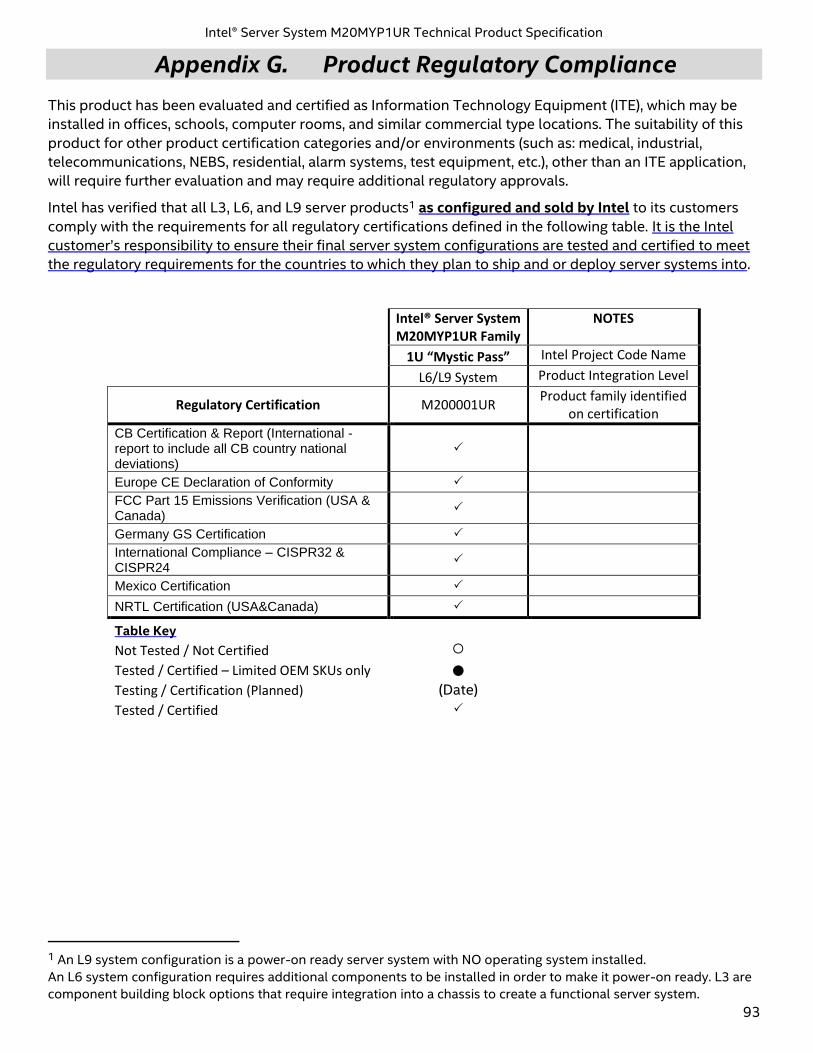
Intel® Server System M20MYP1UR Technical Product Specification
93
Appendix G. Product Regulatory Compliance
This product has been evaluated and certified as Information Technology Equipment (ITE), which may be
installed in offices, schools, computer rooms, and similar commercial type locations. The suitability of this
product for other product certification categories and/or environments (such as: medical, industrial,
telecommunications, NEBS, residential, alarm systems, test equipment, etc.), other than an ITE application,
will require further evaluation and may require additional regulatory approvals.
Intel has verified that all L3, L6, and L9 server products1 as configured and sold by Intel to its customers
comply with the requirements for all regulatory certifications defined in the following table. It is the Intel
customer’s responsibility to ensure their final server system configurations are tested and certified to meet
the regulatory requirements for the countries to which they plan to ship and or deploy server systems into.
Intel® Server System M20MYP1UR Family
NOTES
1U “Mystic Pass” Intel Project Code Name
L6/L9 System Product Integration Level
Regulatory Certification M200001UR Product family identified
on certification
CB Certification & Report (International - report to include all CB country national deviations)
Europe CE Declaration of Conformity
FCC Part 15 Emissions Verification (USA & Canada)
Germany GS Certification
International Compliance – CISPR32 & CISPR24
Mexico Certification
NRTL Certification (USA&Canada)
Table Key
Not Tested / Not Certified
Tested / Certified – Limited OEM SKUs only
Testing / Certification (Planned) (Date)
Tested / Certified
1 An L9 system configuration is a power-on ready server system with NO operating system installed.
An L6 system configuration requires additional components to be installed in order to make it power-on ready. L3 are
component building block options that require integration into a chassis to create a functional server system.
Intel® Server System M20MYP1UR Technical Product Specification
94
EU Directive 2019/424 (Lot 9) Beginning on March 1, 2020, an additional component of the European Union (EU) regulatory CE marking
scheme, identified as EU Directive 2019/424 (Lot 9), will go into effect. After this date, all new server
systems shipped into or deployed within the EU must meet the full CE marking requirements including
those defined by the additional EU Lot 9 regulations.
Intel has verified that all L6, and L9 server products as configured and sold by Intel to its customers
comply with the full CE regulatory requirements for the given product type, including those defined by EU
Lot 9. It is the Intel customer’s responsibility to ensure their final server system configurations are Spec®
SERT™ tested and meet the new CE regulatory requirements.
Visit the following website for additional EU Directive 2019/424 (Lot9) information:
https://eur-lex.europa.eu/legal-content/EN/TXT/?uri=CELEX:32019R0424
In compliance with the EU Directive 2019/424 (Lot 9) materials efficiency requirements, Intel makes
available all necessary product collaterals as identified below:
• Product Serviceability Instructions
o Intel® Server System M20MYP1UR System Integration and Service Guide
o TBD
• Product Specifications
o Intel® Server System M20MYP1UR Technical Product Specification (This document)
o https://www.intel.com/content/www/us/en/support/articles/000056397.html
• System BIOS/Firmware and Security Updates – Intel® Server System M20MYP1UR
o System Update Package (SUP) – uEFI only
o Intel® One Boot Flash Update (OFU) – Various OS Support
o TBD
• Intel Solid State Drive (SSD) Secure Data Deletion and Firmware Updates
o Note: for system configurations that may be configured with an Intel SSD
o Intel® Solid State Drive Toolbox
o https://downloadcenter.intel.com/download/29205?v=t
• Intel® RAID Controller Firmware Updates and other support collaterals
o Note: for system configurations that may be configured with an Intel® RAID Controller
https://www.intel.com/content/www/us/en/support/products/43732/server-products/raid-products.html
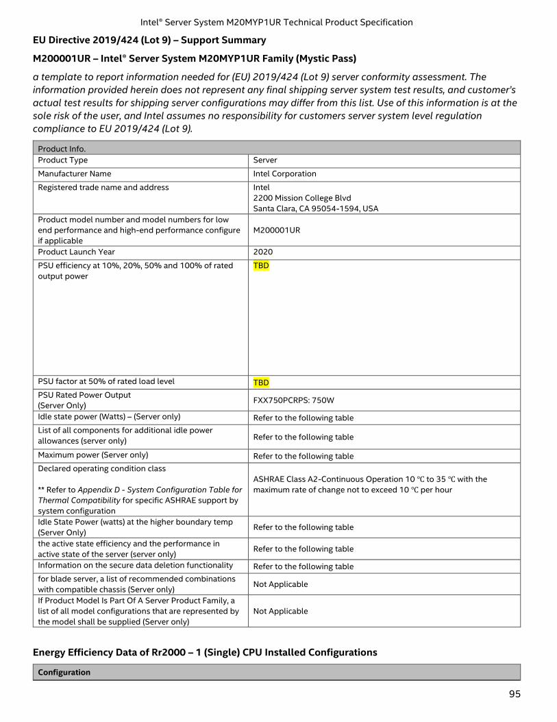
Intel® Server System M20MYP1UR Technical Product Specification
95
EU Directive 2019/424 (Lot 9) – Support Summary
M200001UR – Intel® Server System M20MYP1UR Family (Mystic Pass)
a template to report information needed for (EU) 2019/424 (Lot 9) server conformity assessment. The
information provided herein does not represent any final shipping server system test results, and customer’s
actual test results for shipping server configurations may differ from this list. Use of this information is at the
sole risk of the user, and Intel assumes no responsibility for customers server system level regulation
compliance to EU 2019/424 (Lot 9).
Product Info.
Product Type Server
Manufacturer Name Intel Corporation
Registered trade name and address Intel
2200 Mission College Blvd
Santa Clara, CA 95054-1594, USA
Product model number and model numbers for low
end performance and high-end performance configure
if applicable
M200001UR
Product Launch Year 2020
PSU efficiency at 10%, 20%, 50% and 100% of rated
output power
TBD
PSU factor at 50% of rated load level TBD
PSU Rated Power Output
(Server Only) FXX750PCRPS: 750W
Idle state power (Watts) – (Server only) Refer to the following table
List of all components for additional idle power
allowances (server only) Refer to the following table
Maximum power (Server only) Refer to the following table
Declared operating condition class
** Refer to Appendix D - System Configuration Table for
Thermal Compatibility for specific ASHRAE support by
system configuration
ASHRAE Class A2-Continuous Operation 10 ℃ to 35 ℃ with the
maximum rate of change not to exceed 10 ℃ per hour
Idle State Power (watts) at the higher boundary temp
(Server Only) Refer to the following table
the active state efficiency and the performance in
active state of the server (server only) Refer to the following table
Information on the secure data deletion functionality Refer to the following table
for blade server, a list of recommended combinations
with compatible chassis (Server only) Not Applicable
If Product Model Is Part Of A Server Product Family, a
list of all model configurations that are represented by
the model shall be supplied (Server only)
Not Applicable
Energy Efficiency Data of Rr2000 – 1 (Single) CPU Installed Configurations
Configuration
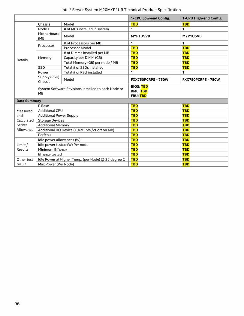
Intel® Server System M20MYP1UR Technical Product Specification
96
1-CPU Low-end Config. 1-CPU High-end Config.
Details
Chassis Model TBD TBD
Node /
Motherboard
(MB)
# of MBs installed in system 1 1
Model MYP1USVB MYP1USVB
Processor # of Processors per MB 1 1
Processor Model TBD TBD
Memory
# of DIMMs installed per MB TBD TBD
Capacity per DIMM (GB) TBD TBD
Total Memory (GB) per node / MB TBD TBD
SSD Total # of SSDs installed TBD TBD
Power
Supply (PSU)
Chassis
Total # of PSU installed 1 1
Model FXX750PCRPS - 750W FXX750PCRPS - 750W
System Software Revisions installed to each Node or
MB
BIOS: TBD
BMC: TBD
FRU: TBD
Data Summary
Measured
and
Calculated
Server
Allowance
P Base TBD TBD
Additional CPU TBD TBD
Additional Power Supply TBD TBD
Storage Devices TBD TBD
Additional Memory TBD TBD
Additional I/O Device (10Gx 15W/2Port on MB) TBD TBD
Perfcpu TBD TBD
Limits/
Results
Idle power allowances (W) TBD TBD
Idle power tested (W) Per node TBD TBD
Minimum EffACTIVE TBD TBD
EffACTIVE tested TBD TBD
Other test
result
Idle Power at Higher Temp. (per Node) @ 35 degree C TBD TBD
Max Power (Per Node) TBD TBD
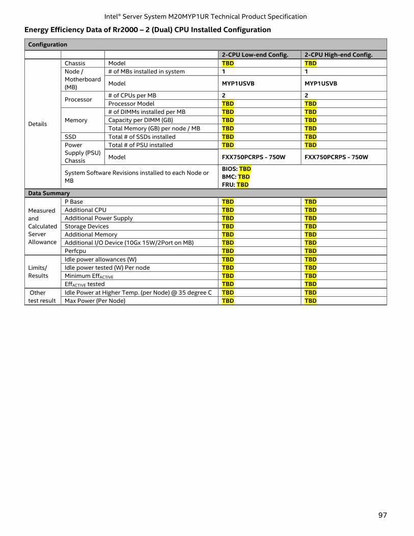
Intel® Server System M20MYP1UR Technical Product Specification
97
Energy Efficiency Data of Rr2000 – 2 (Dual) CPU Installed Configuration
Configuration
2-CPU Low-end Config. 2-CPU High-end Config.
Details
Chassis Model TBD TBD
Node /
Motherboard
(MB)
# of MBs installed in system 1 1
Model MYP1USVB MYP1USVB
Processor # of CPUs per MB 2 2
Processor Model TBD TBD
Memory
# of DIMMs installed per MB TBD TBD
Capacity per DIMM (GB) TBD TBD
Total Memory (GB) per node / MB TBD TBD
SSD Total # of SSDs installed TBD TBD
Power
Supply (PSU)
Chassis
Total # of PSU installed TBD TBD
Model FXX750PCRPS - 750W FXX750PCRPS - 750W
System Software Revisions installed to each Node or
MB
BIOS: TBD
BMC: TBD
FRU: TBD
Data Summary
Measured
and
Calculated
Server
Allowance
P Base TBD TBD
Additional CPU TBD TBD
Additional Power Supply TBD TBD
Storage Devices TBD TBD
Additional Memory TBD TBD
Additional I/O Device (10Gx 15W/2Port on MB) TBD TBD
Perfcpu TBD TBD
Limits/
Results
Idle power allowances (W) TBD TBD
Idle power tested (W) Per node TBD TBD
Minimum EffACTIVE TBD TBD
EffACTIVE tested TBD TBD
Other
test result
Idle Power at Higher Temp. (per Node) @ 35 degree C TBD TBD
Max Power (Per Node) TBD TBD
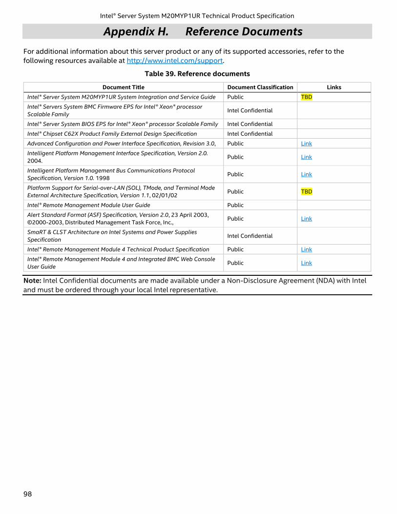
Intel® Server System M20MYP1UR Technical Product Specification
98
Appendix H. Reference Documents
For additional information about this server product or any of its supported accessories, refer to the
following resources available at http://www.intel.com/support.
Table 39. Reference documents
Document Title Document Classification Links
Intel® Server System M20MYP1UR System Integration and Service Guide Public TBD
Intel® Servers System BMC Firmware EPS for Intel® Xeon® processor
Scalable Family Intel Confidential
Intel® Server System BIOS EPS for Intel® Xeon® processor Scalable Family Intel Confidential
Intel® Chipset C62X Product Family External Design Specification Intel Confidential
Advanced Configuration and Power Interface Specification, Revision 3.0, Public Link
Intelligent Platform Management Interface Specification, Version 2.0.
2004. Public Link
Intelligent Platform Management Bus Communications Protocol
Specification, Version 1.0. 1998 Public Link
Platform Support for Serial-over-LAN (SOL), TMode, and Terminal Mode
External Architecture Specification, Version 1.1, 02/01/02 Public TBD
Intel® Remote Management Module User Guide Public
Alert Standard Format (ASF) Specification, Version 2.0, 23 April 2003,
©2000-2003, Distributed Management Task Force, Inc., Public Link
SmaRT & CLST Architecture on Intel Systems and Power Supplies
Specification Intel Confidential
Intel® Remote Management Module 4 Technical Product Specification Public Link
Intel® Remote Management Module 4 and Integrated BMC Web Console
User Guide Public Link
Note: Intel Confidential documents are made available under a Non-Disclosure Agreement (NDA) with Intel
and must be ordered through your local Intel representative.
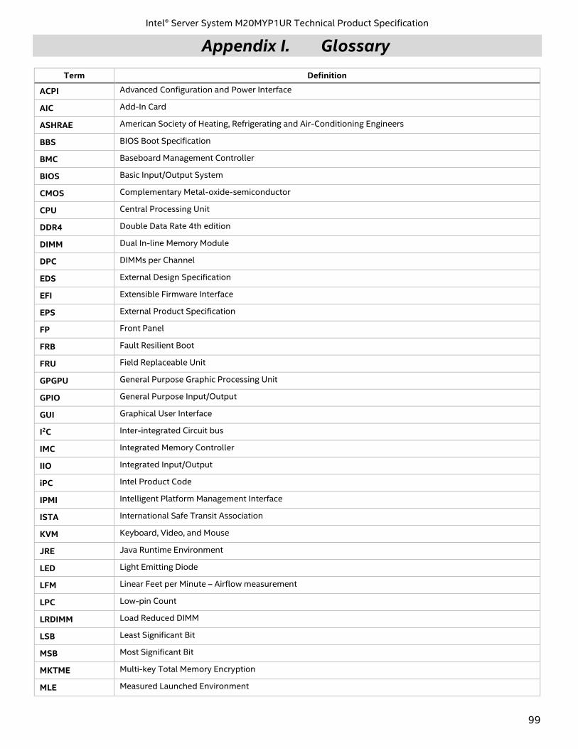
Intel® Server System M20MYP1UR Technical Product Specification
99
Appendix I. Glossary
Term Definition
ACPI Advanced Configuration and Power Interface
AIC Add-In Card
ASHRAE American Society of Heating, Refrigerating and Air-Conditioning Engineers
BBS BIOS Boot Specification
BMC Baseboard Management Controller
BIOS Basic Input/Output System
CMOS Complementary Metal-oxide-semiconductor
CPU Central Processing Unit
DDR4 Double Data Rate 4th edition
DIMM Dual In-line Memory Module
DPC DIMMs per Channel
EDS External Design Specification
EFI Extensible Firmware Interface
EPS External Product Specification
FP Front Panel
FRB Fault Resilient Boot
FRU Field Replaceable Unit
GPGPU General Purpose Graphic Processing Unit
GPIO General Purpose Input/Output
GUI Graphical User Interface
I2C Inter-integrated Circuit bus
IMC Integrated Memory Controller
IIO Integrated Input/Output
iPC Intel Product Code
IPMI Intelligent Platform Management Interface
ISTA International Safe Transit Association
KVM Keyboard, Video, and Mouse
JRE Java Runtime Environment
LED Light Emitting Diode
LFM Linear Feet per Minute – Airflow measurement
LPC Low-pin Count
LRDIMM Load Reduced DIMM
LSB Least Significant Bit
MSB Most Significant Bit
MKTME Multi-key Total Memory Encryption
MLE Measured Launched Environment
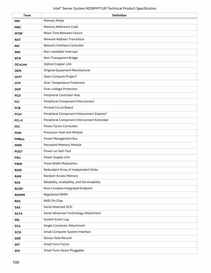
Intel® Server System M20MYP1UR Technical Product Specification
100
Term Definition
MM Memory Mode
MRC Memory Reference Code
MTBF Mean Time Between Failure
NAT Network Address Translation
NIC Network Interface Controller
NMI Non-maskable Interrupt
NTB Non-Transparent Bridge
OCuLink Optical Copper Link
OEM Original Equipment Manufacturer
OCP* Open Compute Project*
OTP Over Temperature Protection
OVP Over-voltage Protection
PCH Peripheral Controller Hub
PCI Peripheral Component Interconnect
PCB Printed Circuit Board
PCIe* Peripheral Component Interconnect Express*
PCI-X Peripheral Component Interconnect Extended
PFC Power Factor Correction
PHM Processor Heat sink Module
PMBus Power Management Bus
PMM Persistent Memory Module
POST Power-on Self-Test
PSU Power Supply Unit
PWM Pulse Width Modulation
RAID Redundant Array of Independent Disks
RAM Random Access Memory
RAS Reliability, Availability, and Serviceability
RCiEP Root Complex Integrated Endpoint
RDIMM Registered DIMM
ROC RAID On Chip
SAS Serial Attached SCSI
SATA Serial Advanced Technology Attachment
SEL System Event Log
SCA Single Connector Attachment
SCSI Small Computer System Interface
SDR Sensor Data Record
SFF Small Form Factor
SFP Small Form-factor Pluggable
Intel® Server System M20MYP1UR Technical Product Specification
101
Term Definition
SMBus System Management Bus
SSD Solid State Device
TCG Trusted Computing Group
TDP Thermal Design Power
TPM Trusted Platform Module
TPS Technical Product Specification
Intel® TXT Intel® Trusted Execution Technology
VLSI Very Large Scale Integration
VSB Voltage Standby
Intel® VROC Intel® Virtual RAID on CPU