Embed Size (px)
Citation preview
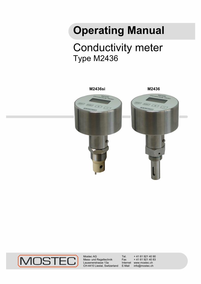
Operating Manual
Conductivity meter Type M2436
M2436si M2436
Mostec AG Mess- und Regeltechnik Lausenerstrasse 13a CH-4410 Liestal, Switzerland
Tel. + 41 61 921 40 90 Fax + 41 61 921 40 83 Internet www.mostec.ch E-Mail [email protected]

V1.06 © 30.11.2010 MOSTEC AG, CH-4410 Liestal 2
M2436 Operating Manual
V1.06 © 30.11.2010 MOSTEC AG, CH-4410 Liestal 2
Warranty Mostec warrants this product to be free of manufacturing defects for a 2-year period after the original date of purchase. Within this period, defective products will be repaired free of charge provided that the defect occurred during normal operation. This warranty does not cover damage to the product resulting from ordinary usage such as front panel scratches, broken control elements and corrosion, etc. The customer is responsible for shipping and packing charges for products returned under warranty to Mostec. Mostec warrants this product beyond the 2-year warranty period for an additional 2 years in case of long term damages due to improper manufacturing. Such damages as poorly soldered joints or other assembly problems are also covered by the warranty. Transportation damages are not covered by the warranty and should be referred to the respective delivery service. Technical description The M2436 conductivity meter is mounted in +/-180° turnable, water resistant, stainless steel case. Any commercially available conductivity cell’s, K-factor 0.01, 0.1, 1.0 and 10.0, which cover a dynamic range from 0.01µS to 20mS full scale can be used. The cell is simply assembled to the desired measuring unit and directly attached to the M2436. The conductivity meter is suitable for water, waste water or ultrapure water conditioning in continuous or batch-type operating modes, for liquid chromatography or for general chemical process monitoring. Temperature coefficient of the cell is compensated either manually or automatically by a Pt-100 platinum probe within the range of 0°C to 130°C. The 8x2 LCD character display shows the currently measured conductivity and the process temperature. These values are available at two galvanic isolated outputs of 0...20mA or 4...20mA. The M2436 is powered by either 24VAC or DC. Optionally, all measuring ranges are externally selectable with digital control wires during the measurement process. Two isolated, free limit contacts are also optionally available to control valves or other control elements. Supply lines and all other lines, either from or to the conductivity meter, are protected by internal noise filters against HF-noise. A cable of either 2m or 5m is used to connect the M2436si signals and power supply.
V1.06 © 30.11.2010 MOSTEC AG, CH-4410 Liestal 3
M2436 Operating Manual
V1.06 © 30.11.2010 MOSTEC AG, CH-4410 Liestal 3
Index: Page A. Front panel control 4 B. How to change the cell’s K-factor 4 C. How to change the measurement range by menu 4/5 D. How to change the measurement range by external control ** 5 E. How to change the temperature compensation to Pt100 6 F. How to change the temperature compensation to manual 6 G. How to change the temperature slope %/ºC 6 H. How to change the cell correction factor 7 J. How to change the current output for conductivity 7 K. How to change the current output for temperature 8 L. How to adjust the limit contacts ** 9 M. Menu protection with access code 9 N. Error codes 10 O. Technical data 11 P. Dimensions 12 Q. Installation note 12 ** Note: This function is an option
V1.06 © 30.11.2010 MOSTEC AG, CH-4410 Liestal 4
M2436 Operating Manual
V1.06 © 30.11.2010 MOSTEC AG, CH-4410 Liestal 4
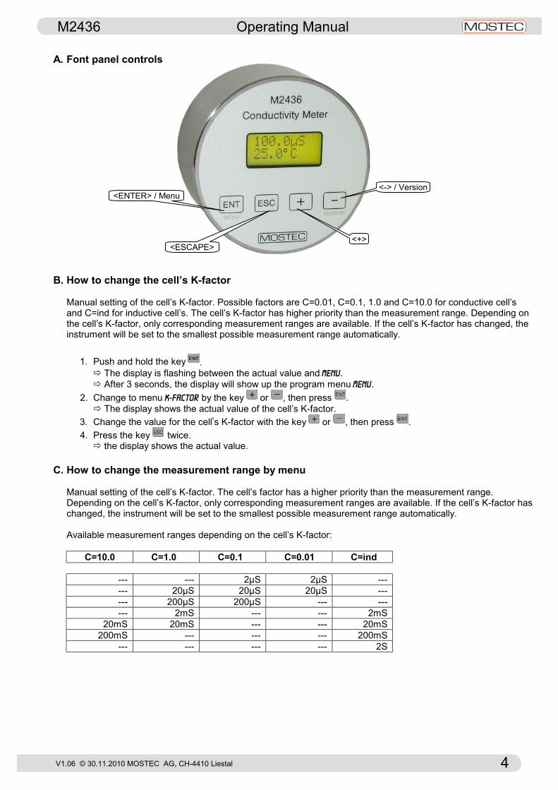
A. Font panel controls
B. How to change the cell’s K-factor
Manual setting of the cell’s K-factor. Possible factors are C=0.01, C=0.1, 1.0 and C=10.0 for conductive cell’s and C=ind for inductive cell’s. The cell’s K-factor has higher priority than the measurement range. Depending on the cell’s K-factor, only corresponding measurement ranges are available. If the cell’s K-factor has changed, the instrument will be set to the smallest possible measurement range automatically.
1. Push and hold the key . ð The display is flashing between the actual value and MENU. ð After 3 seconds, the display will show up the program menu MENU.
2. Change to menu K-factor by the key or , then press . ð The display shows the actual value of the cell’s K-factor.
3. Change the value for the cell’s K-factor with the key or , then press . 4. Press the key twice.
ð the display shows the actual value. C. How to change the measurement range by menu
Manual setting of the cell’s K-factor. The cell’s factor has a higher priority than the measurement range. Depending on the cell’s K-factor, only corresponding measurement ranges are available. If the cell’s K-factor has changed, the instrument will be set to the smallest possible measurement range automatically. Available measurement ranges depending on the cell’s K-factor:
C=10.0 C=1.0 C=0.1 C=0.01 C=ind
--- --- 2µS 2µS --- --- 20µS 20µS 20µS --- --- 200µS 200µS --- --- --- 2mS --- --- 2mS
20mS 20mS --- --- 20mS 200mS --- --- --- 200mS
--- --- --- --- 2S
<ENTER> / Menu
<ESCAPE>
<-> / Version
<+>

V1.06 © 30.11.2010 MOSTEC AG, CH-4410 Liestal 5
M2436 Operating Manual
V1.06 © 30.11.2010 MOSTEC AG, CH-4410 Liestal 5
1. Push and hold the key . ð The display is flashing between the actual value and MENU. ð After 3 seconds, the display will show up the program menu MENU.
2. press ð The display shows the actual value of the measurement range.
3. Change the value for the measurement range with the key or , then press . 4. Press the key twice.
ð the display shows the actual value. D. How to change the measurement range with externally control wires
Optionally, all measuring ranges are externally selectable with digital control wires during the measuring process. The measurement range will be set by signals on the connector St2 with external 24V supply and digital control wires. Depending on the cell’s K-factor, only corresponding measurement ranges are available. If the selected cell’s K-factor is not possible, the instrument indicates an error code (see chapter M, page 9). If no digital control wires are connected, the instrument select’s the internal measurement range automatically. Available measurement ranges set by external control wires:
St2 (white) St2 (brown) St2 (yellow) St2 (blue) Range kond. Range ind.
GND 0V 0V 0V intern intern GND +24V +24V +24V 2uS 2mS GND 0V +24V +24V 20uS 20mS GND +24V 0V +24V 200uS 200mS GND 0V 0V +24V 2mS 2S GND +24V +24V 0V 20mS --- GND 0V +24V 0V 200mS ---
Available measurement ranges depending on the cell’s K-factor:
C=10.0 C=1.0 C=0.1 C=0.01 C=ind
--- --- 2µS 2µS --- --- 20µS 20µS 20µS --- --- 200µS 200µS --- --- --- 2mS --- --- 2mS
20mS 20mS --- --- 20mS 200mS --- --- --- 200mS
--- --- --- --- 2S

V1.06 © 30.11.2010 MOSTEC AG, CH-4410 Liestal 6
M2436 Operating Manual
V1.06 © 30.11.2010 MOSTEC AG, CH-4410 Liestal 6
E. How to change the temperature compensation to Pt100
If the M2436 is set to Pt100 and the Pt100 sensor is not connected, damaged, or the temperature is higher than 135ºC, the processor internally uses a temperature value of 135ºC and the display value is flashing. If the temperature is lower than -10°C, the processor internally uses a temperature value of -10ºC and the display value is flashing. If a inductive cell is used and the temperature is higher than 125ºC, the instrument indicates an error code (see chapter M, page 9). Because no correct signals are possible at this high temperature.
1. Push and hold the key . ð The display is flashing between the actual value and MENU. ð After 3 seconds, the display will show up the program menu MENU. 2. Change to menu Man/Auto by the key or , then press . 3. Change the value to AUTO with the key or , then press .
4. Press the key twice. ð the display shows the actual value. F. How to change the temperature compensation to manual 1. Push and hold the key . ð The display is flashing between the actual value and MENU. ð After 3 seconds, the display will show up the program menu MENU.
2. Change to menu Temp.Man by the key or , then press . ð The display shows the actual value of the manual temperature.
3. Change the value for the temperature with the key or , then press . 4. Change to menu Man/Auto by the key or , then press . 3. Change the value to MAN with the key or , then press .
4. Press the key . ð the display shows the actual value. G. How to change the temperature slope %/ºC
All liquids have a positive temperature coefficient, expressed in %/ºC conductivity change. The higher the temperature the lower the electrical resistance which is equal to higher siemens values. Water has a slope of about 2.25%/ºC. The temperature slope should be set in such a way, to display a constant conductivity value when the temperature only changes. Example: The conductivity is 15.5µS at a temperature of 20ºC. Now increase the temperature to 30ºC, without chemically changing the medium. The conductivity must still show 15.5µS. When the displayed conductivity value changes, the temperature slope requires readjustment. Measuring the absolute conductivity at 25ºC: You may switch off the temperature compensation by simply selecting slope 0.0%/ºC. The indicated values are now not temperature compensated.
1. Push and hold the key . ð The display is flashing between the actual value and MENU. ð After 3 seconds, the display will show up the program menu MENU. 2. Change to menu Slope by the key or , then press .
ð The display shows the actual value of the temperature slope. 3. Change the value for the temperature slope with the key or , then press .
4. Press the key . ð the display shows the actual value.
V1.06 © 30.11.2010 MOSTEC AG, CH-4410 Liestal 7
M2436 Operating Manual
V1.06 © 30.11.2010 MOSTEC AG, CH-4410 Liestal 7
H. How to change the cell correction factor If the conductivity cell has a special K-factor outside of K=1.0, K=0.1 and K=0.01, the value can be adjusted with the cell correction factor. Factory set value of K is 1.000. If you have to change this value, the calibration of the M2136 is maintained, but the displayed conductivity value is no longer the standard calibration.
1. Push and hold the key . ð The display is flashing between the actual value and MENU. ð After 3 seconds, the display will show up the program menu MENU.
2. Change to menu GAIn by the key or , then press . ð The display shows the actual value of cell correction factor.
3. Change the value for the correction factor with the key or , then press . 4. Press the key .
ð the display shows the actual value. J. How to change the current output for conductivity
The current output relates to the selected measurement range and can be set in the range of 0…20mA.
1. Push and hold the key . ð The display is flashing between the actual value and MENU. ð After 3 seconds, the display will show up the program menu MENU.
2. Change to menu Out–LW by the key or , then press . 3. Change Zero for the lower current value, or GAIN for the upper value by the key or , then press . 4. Change the value for the current output with the key or , then press .
5. Press the key twice. ð the display shows the actual value.
In addition, the current span can be set in percent for the conductivity measurement. Example: current span = 100.0% (standart), range = 0…2mS, current output = 4…20mA
ð 0…2mS = 4…20mA new current span = 50.0%, range = 0…2mS, current output = 4…20mA
ð 0…1mS = 4…20mA
1. Push and hold the key . ð The display is flashing between the actual value and MENU. ð After 3 seconds, the display will show up the program menu MENU.
2. Change to menu Range LW by the key or , then press . ð the display shows End Val, then press .
3. Change the value for the current span output (10…100.0%) with the key or , then press . 4. Press the key twice.
ð the display shows the actual value.
V1.06 © 30.11.2010 MOSTEC AG, CH-4410 Liestal 8
M2436 Operating Manual
V1.06 © 30.11.2010 MOSTEC AG, CH-4410 Liestal 8
K. How to change the signal current output for temperature
The current output relates to the measurement range of 0…130ºC and can be set in the range of 0…20mA.
1. Push and hold the key . ð The display is flashing between the actual value and MENU. ð After 3 seconds, the display will show up the program menu MENU.
2. Change to menu Out–TEMP by the key or , then press . 3. Change Zero for the lower current value, or GAIN for the upper value by the key or , then press . 4. Change the value for the current output with the key or , then press .
5. Press the key twice. ð the display shows the actual value.
In addition, the current span can be set for the temperature measurement. Example: current span = 130.0ºC (standart), current output = 4…20mA
ð 0…130.0ºC = 4…20mA new current span = 100.0ºC, current output = 4…20mA
ð 0…100.0ºC = 4…20mA
1. Push and hold the key . ð The display is flashing between the actual value and MENU. ð After 3 seconds, the display will show up the program menu MENU.
2. Change to menu Range TP by the key or , then press . ð the display shows End Val, then press .
3. Change the value for the current span output (10…130ºC) with the key or , then press . 4. Press the key twice.
ð the display shows the actual value.
V1.06 © 30.11.2010 MOSTEC AG, CH-4410 Liestal 9
M2436 Operating Manual
V1.06 © 30.11.2010 MOSTEC AG, CH-4410 Liestal 9
L. How to adjust the limit contacts The instrument is available with 2 limit contacts. They can be set over the intire measurement range. If the measurement range changes, the limit contacts for all other measurement ranges will be set to the new value automatically.
ð E.g. the measurement range is set to 20.00 µS and the limit contact is set to 10.00 µS. If the measurement range changes to 200.0 µS, the limit contact will be set to 100.0 µS. 1. Push and hold the key . ð The display is flashing between the actual value and MENU. ð After 3 seconds, the display will show up the program menu MENU.
2. Change to menu SP1 for limit contact 1 or SP2 for limit contact 2 by the key or , then press . ð the display shows the actual value.
3. Change the value for the limit contact with the key or , then press . 4. Change to menu HYS1 for limit contact 1 or HYS2 for limit contact 2 by the key or , then press . ð the display shows the actual value.
5. Change the value for the hysteresis with the key or , then press . 6. Change to menu REL1 for limit contact 1 or REL2 for limit contact 2 by the key or , then press. ð the display shows the actual value.
7. Change the value for the switching method of the relays with the key or , then press . "nor": Relays ON, when input > limit contact value (normally open) "inv": Relays ON, when input < limit contact value (normally closed)
8. Press the key twice. ð the display shows the actual value. M. Menu protection with access code The contents in the user menus can be protected from unintended access, using an access code. After activating the access code, menu values can be displayed but no longer modified. To modify setpoints and other parameters, the access code has to be set to the value 0. If the code has a value different from 0, writing to the user menu is suppressed. Call Mostec if the access code is lost or unavailable.
Set the access code: 1. Push and hold the key .
ð The display is flashing between the actual value and MENU. ð After 3 seconds, the display will show up the program menu MENU.
2. Now navigate to the Code menu item by the key , then press . a) A code has already been entered: The display shows Code ON. Enter now the valid access code with the keys and and confirm with the key. If the code is wrong, the display shows wrong!. If the code is correct, the display shows CODE OFF and 0. It the can be modified with the keys and , or in order to make changes to the user menu, set to 0, then confirm with the key. b) No code has been entered: The display shows 0. A code can be entered with the keys and ,
then confirm with the key. If you do not need the user menu protection, leave the value 0 unchanged and quit the menu with the key. The entered code should be placed on a save place to have access to it long time periods later.

V1.06 © 30.11.2010 MOSTEC AG, CH-4410 Liestal 10
M2436 Operating Manual
V1.06 © 30.11.2010 MOSTEC AG, CH-4410 Liestal 10
N. Error codes Error codes with conductive cell and external range control:
With the external range control, the range can be set to a impossible range. LCD Display: Reason: - The range is too low for the corresponding programmed cell’s K-factor. à current output conductivity = <4, (<0) mA - The range is too high for the corresponding programmed cell’s K-factor.
à current output conductivity > 22mA
Select range between 20.00µS and 20.00mS Error codes with inductive cell and external range control:
With the external range control, the range can be set to an impossible range. At a measured temperature higher than 125.0°C, no accurate measurement is possible anymore.
LCD Display: Reason
- The range is not possible for the corresponding programmed cell’s K-factor. à current output conductivity > 22mA Select range with digital control wires! Lower or cool down the medium temperature!
Error!
Err 123
Error!
Err 322
Error!
Err 322
V1.06 © 30.11.2010 MOSTEC AG, CH-4410 Liestal 11
M2436 Operating Manual
V1.06 © 30.11.2010 MOSTEC AG, CH-4410 Liestal 11
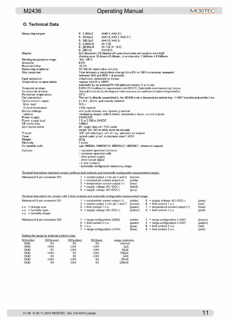
O. Technical Data
V1.06 © 30.11.2010 MOSTEC AG, CH-4410 Liestal 12
M2436 Operating Manual
V1.06 © 30.11.2010 MOSTEC AG, CH-4410 Liestal 12
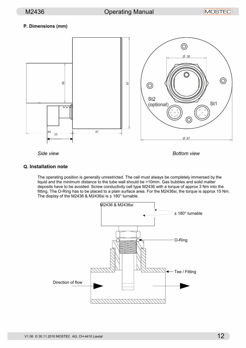
P. Dimensions (mm)
Q. Installation note The operating position is generally unrestricted. The cell must always be completely immersed by the liquid and the minimum distance to the tube wall should be >10mm. Gas bubbles and solid matter
deposits have to be avoided. Screw conductivity cell type M2436 with a torque of approx 3 Nm into the fitting. The O-Ring has to be placed to a plain surface area. For the M2436si, the torque is approx 15 Nm. The display of the M2436 & M2436si is ± 180° turnable.
V1.04 03.09.2010 © 2002 MOSTEC AG
35
M2436 & M2436si
Direction of flow
Tee / Fitting
O-Ring
± 180° turnable
Side view Bottom view