Embed Size (px)
Citation preview
M2794.0027 Introduction to RoboticsMidterm Examination11-12pm, 2020 May 14
CLOSED BOOK, CLOSED NOTES
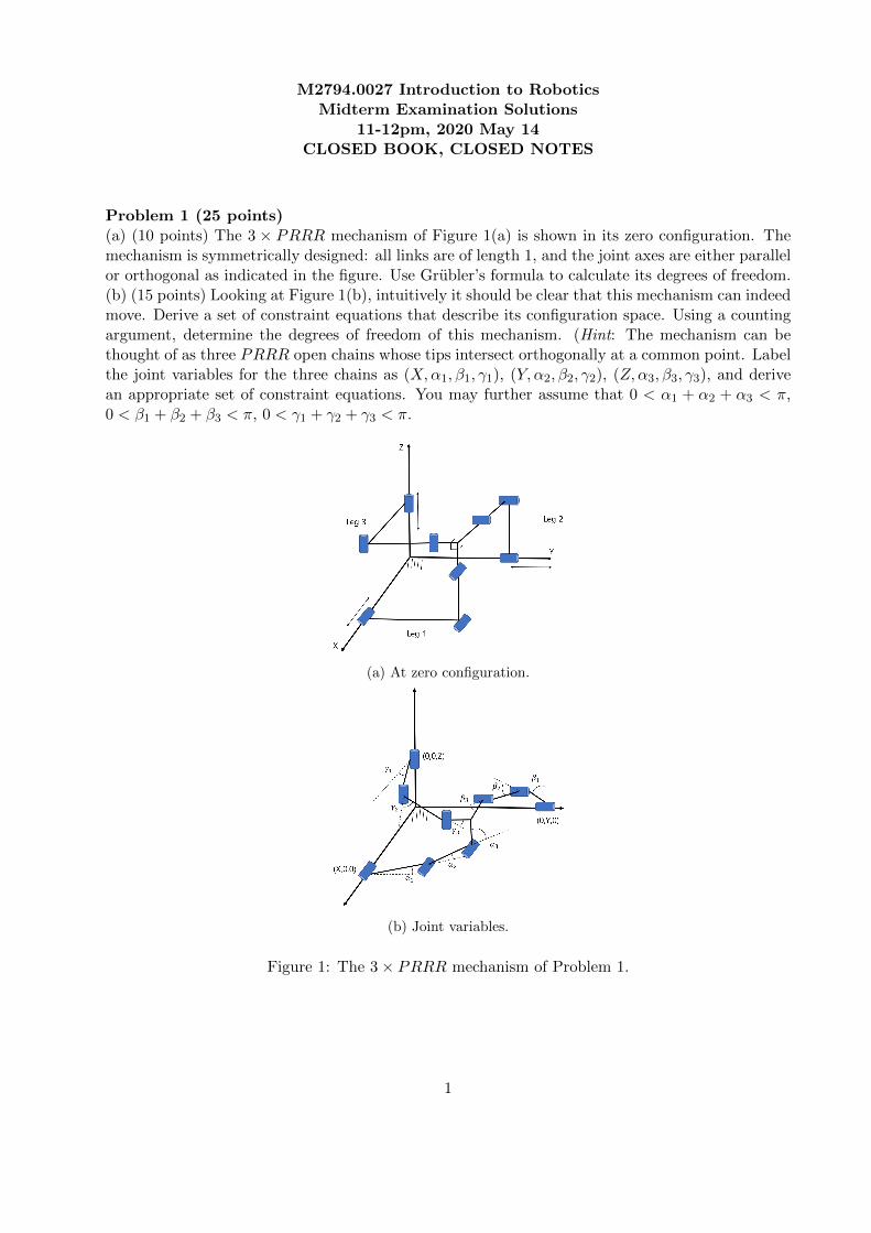
Problem 1 (25 points)(a) (10 points) The 3 × PRRR mechanism of Figure 1(a) is shown in its zero configuration. Themechanism is symmetrically designed: all links are of length 1, and the joint axes are either parallelor orthogonal as indicated in the figure. Use Grubler’s formula to calculate its degrees of freedom.(b) (15 points) Looking at Figure 1(b), intuitively it should be clear that this mechanism can indeedmove. Derive a set of constraint equations that describe its configuration space. Using a countingargument, determine the degrees of freedom of this mechanism. (Hint: The mechanism can bethought of as three PRRR open chains whose tips intersect orthogonally at a common point. Labelthe joint variables for the three chains as (X,α1, β1, γ1), (Y, α2, β2, γ2), (Z,α3, β3, γ3), and derivean appropriate set of constraint equations. You may further assume that 0 < α1 + α2 + α3 < π,0 < β1 + β2 + β3 < π, 0 < γ1 + γ2 + γ3 < π.
(a) At zero configuration.
(b) Joint variables.
Figure 1: The 3× PRRR mechanism of Problem 1.
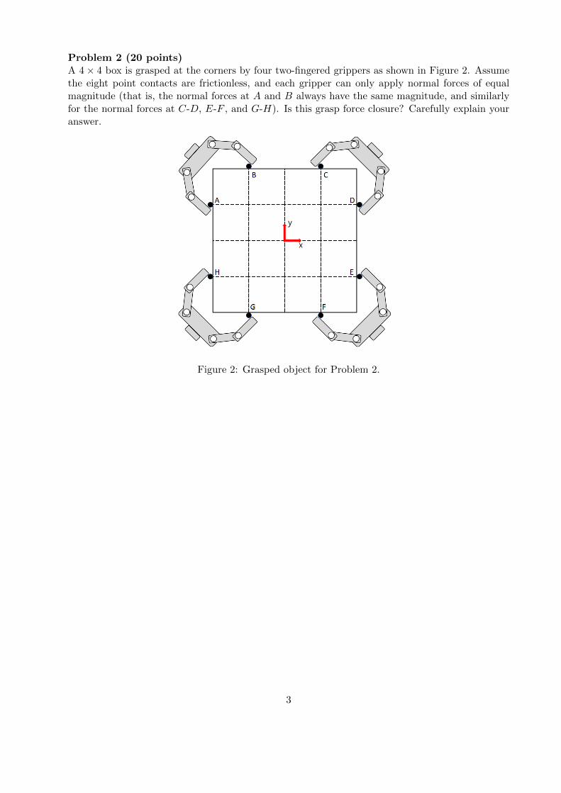
Problem 2 (20 points)A 4× 4 box is grasped at the corners by four two-fingered grippers as shown in Figure 2. Assume
1
the eight point contacts are frictionless, and each gripper can only apply normal forces of equalmagnitude (that is, the normal forces at A and B always have the same magnitude, and similarlyfor the normal forces at C-D, E-F , and G-H). Is this grasp force closure? Carefully explain youranswer.
Figure 2: Grasped object for Problem 2.
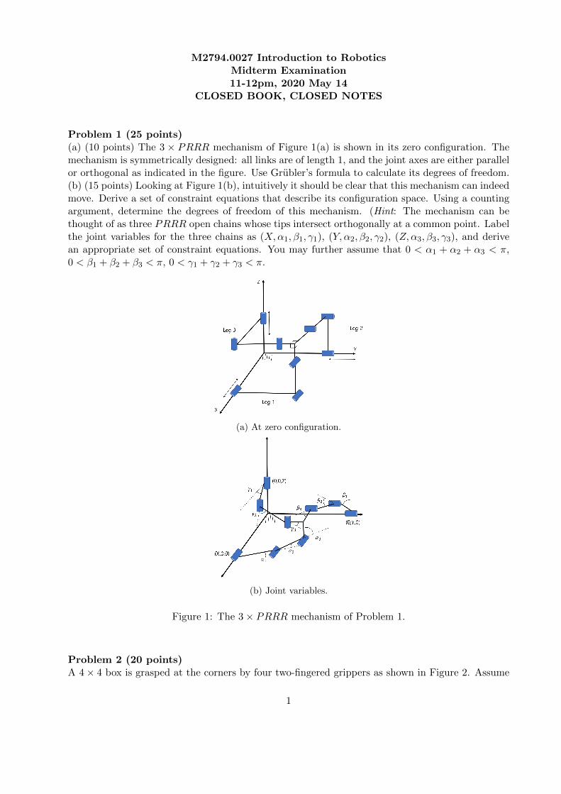
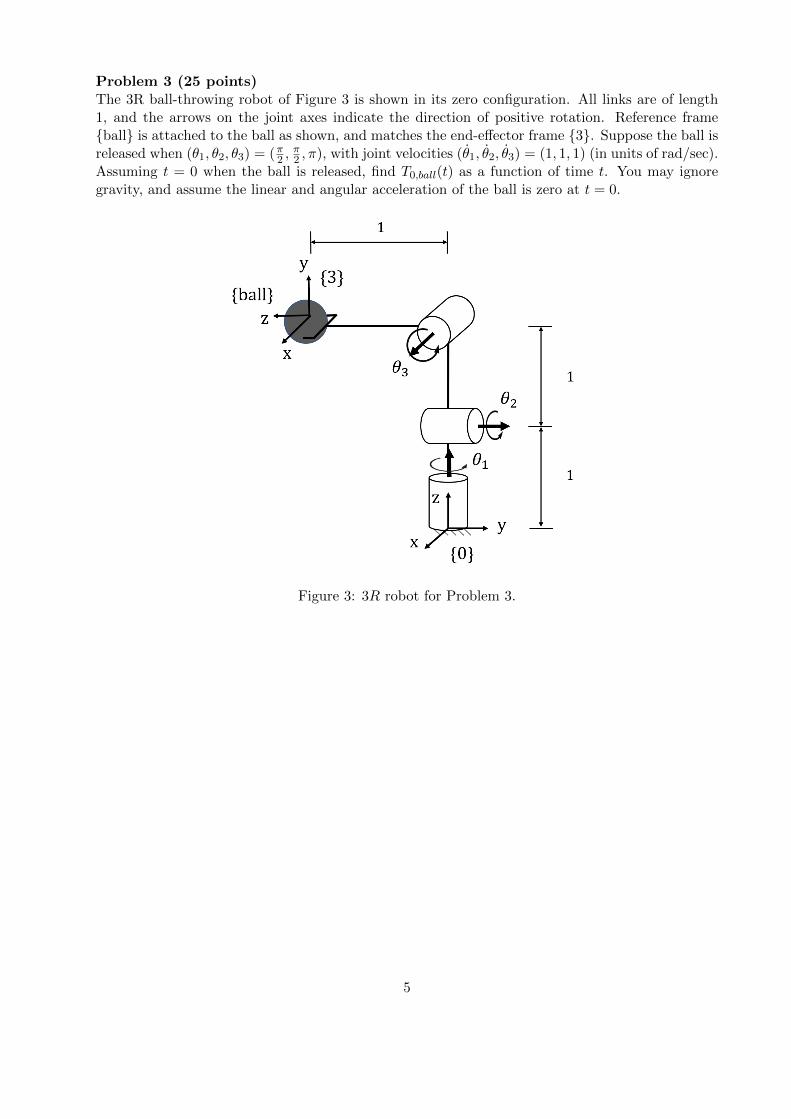
Problem 3 (25 points)The 3R ball-throwing robot of Figure 3 is shown in its zero configuration. All links are of length1, and the arrows on the joint axes indicate the direction of positive rotation. Reference frame{ball} is attached to the ball as shown, and matches the end-effector frame {3}. Suppose the ball isreleased when (θ1, θ2, θ3) = (π2 ,
π2 , π), with joint velocities (θ1, θ2, θ3) = (1, 1, 1) (in units of rad/sec).
Assuming t = 0 when the ball is released, find T0,ball(t) as a function of time t. You may ignoregravity, and assume the linear and angular acceleration of the ball is zero at t = 0.
2
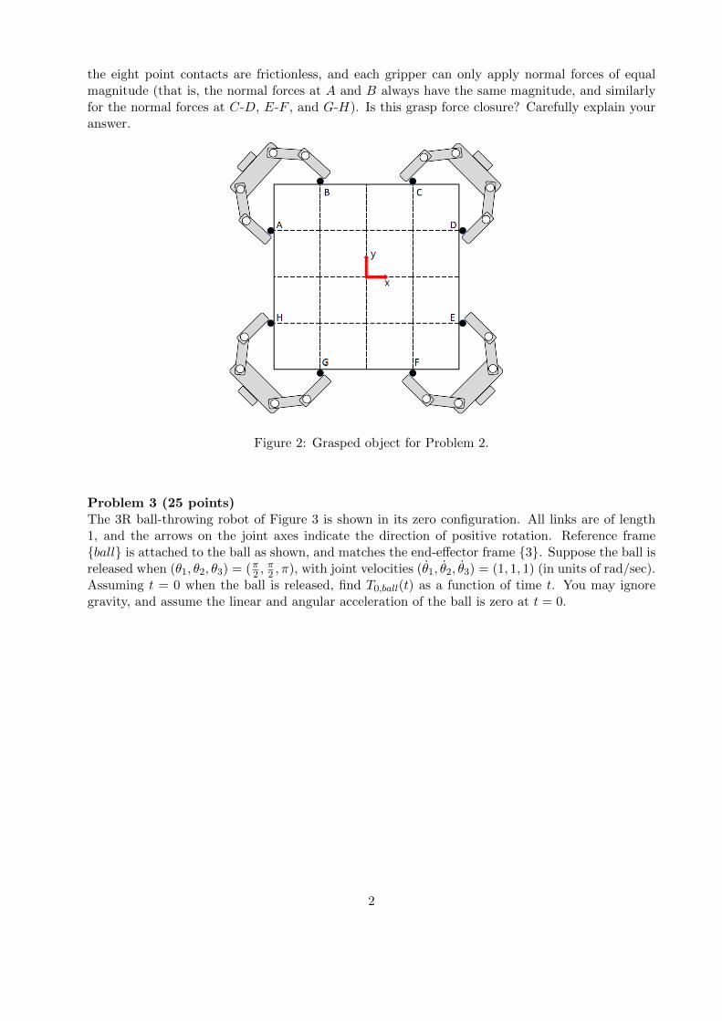
Problem 4 (30 points)
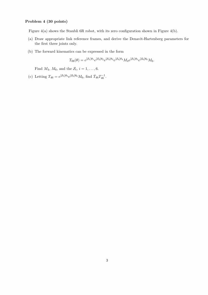
Figure 4(a) shows the Staubli 6R robot, with its zero configuration shown in Figure 4(b).
(a) Draw appropriate link reference frames, and derive the Denavit-Hartenberg parameters forthe first three joints only.
(b) The forward kinematics can be expressed in the form
T06(θ) = e[S1]θ1e[S2]θ2e[S3]θ3e[S4]θ4M4e[S5]θ5e[S6]θ6M6.
Find M4, M6, and the Si, i = 1, . . . , 6.
(c) Letting T46 = e[S5]θ5e[S6]θ6M6, find T46T−146 .
3
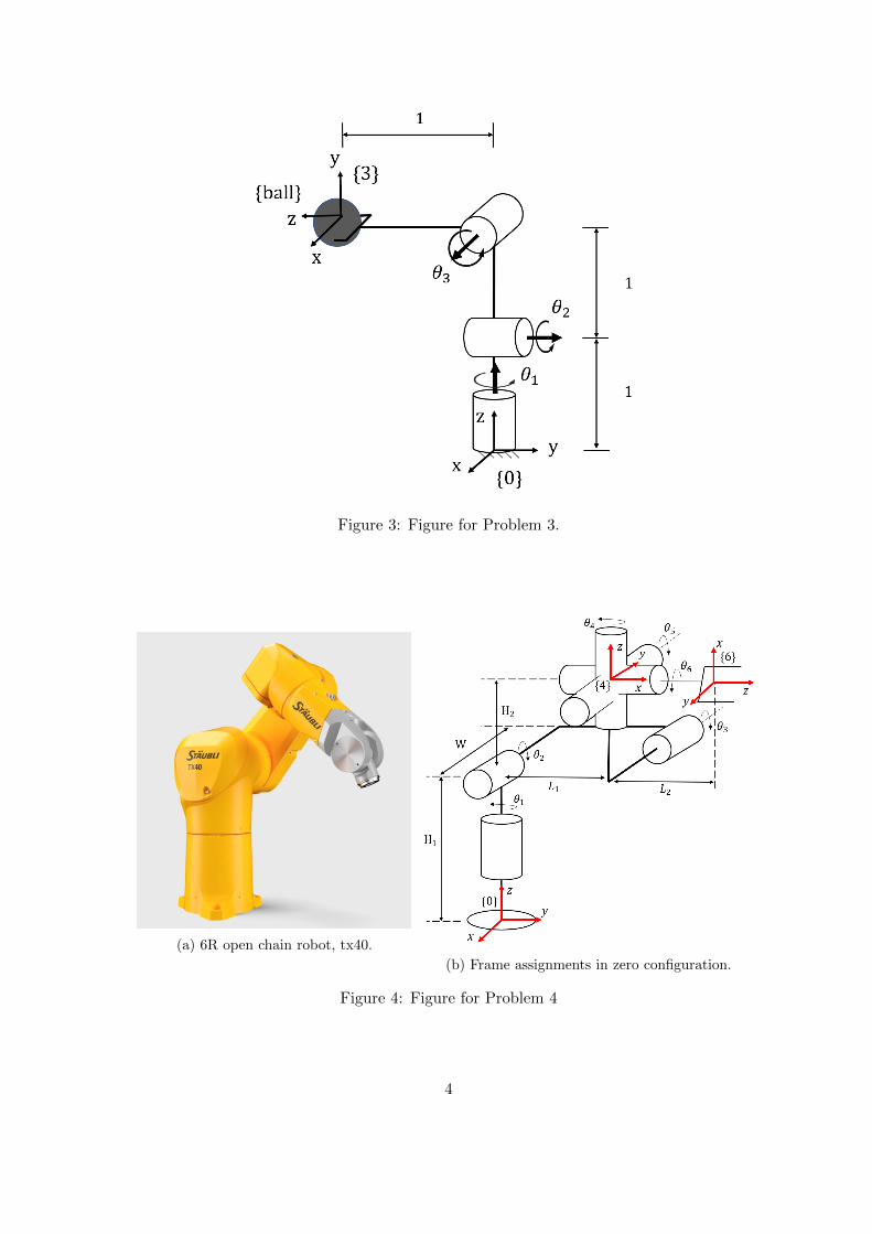
Figure 3: Figure for Problem 3.
(a) 6R open chain robot, tx40.
(b) Frame assignments in zero configuration.
Figure 4: Figure for Problem 4
4
M2794.0027 Introduction to RoboticsMidterm Examination Solutions
11-12pm, 2020 May 14CLOSED BOOK, CLOSED NOTES
Problem 1 (25 points)(a) (10 points) The 3 × PRRR mechanism of Figure 1(a) is shown in its zero configuration. Themechanism is symmetrically designed: all links are of length 1, and the joint axes are either parallelor orthogonal as indicated in the figure. Use Grubler’s formula to calculate its degrees of freedom.(b) (15 points) Looking at Figure 1(b), intuitively it should be clear that this mechanism can indeedmove. Derive a set of constraint equations that describe its configuration space. Using a countingargument, determine the degrees of freedom of this mechanism. (Hint: The mechanism can bethought of as three PRRR open chains whose tips intersect orthogonally at a common point. Labelthe joint variables for the three chains as (X,α1, β1, γ1), (Y, α2, β2, γ2), (Z,α3, β3, γ3), and derivean appropriate set of constraint equations. You may further assume that 0 < α1 + α2 + α3 < π,0 < β1 + β2 + β3 < π, 0 < γ1 + γ2 + γ3 < π.
(a) At zero configuration.
(b) Joint variables.
Figure 1: The 3× PRRR mechanism of Problem 1.
1
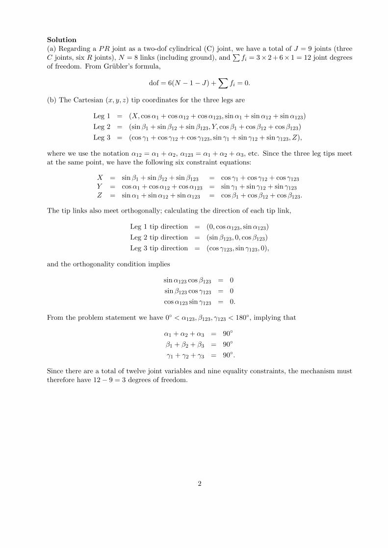
Solution(a) Regarding a PR joint as a two-dof cylindrical (C) joint, we have a total of J = 9 joints (threeC joints, six R joints), N = 8 links (including ground), and
∑fi = 3× 2 + 6× 1 = 12 joint degrees
of freedom. From Grubler’s formula,
dof = 6(N − 1− J) +∑
fi = 0.
(b) The Cartesian (x, y, z) tip coordinates for the three legs are
Leg 1 = (X, cosα1 + cosα12 + cosα123, sinα1 + sinα12 + sinα123)
Leg 2 = (sinβ1 + sinβ12 + sinβ123, Y, cosβ1 + cosβ12 + cosβ123)
Leg 3 = (cos γ1 + cos γ12 + cos γ123, sin γ1 + sin γ12 + sin γ123, Z),
where we use the notation α12 = α1 + α2, α123 = α1 + α2 + α3, etc. Since the three leg tips meetat the same point, we have the following six constraint equations:
X = sinβ1 + sinβ12 + sinβ123 = cos γ1 + cos γ12 + cos γ123Y = cosα1 + cosα12 + cosα123 = sin γ1 + sin γ12 + sin γ123Z = sinα1 + sinα12 + sinα123 = cosβ1 + cosβ12 + cosβ123.
The tip links also meet orthogonally; calculating the direction of each tip link,
Leg 1 tip direction = (0, cosα123, sinα123)
Leg 2 tip direction = (sinβ123, 0, cosβ123)
Leg 3 tip direction = (cos γ123, sin γ123, 0),
and the orthogonality condition implies
sinα123 cosβ123 = 0
sinβ123 cos γ123 = 0
cosα123 sin γ123 = 0.
From the problem statement we have 0◦ < α123, β123, γ123 < 180◦, implying that
α1 + α2 + α3 = 90◦
β1 + β2 + β3 = 90◦
γ1 + γ2 + γ3 = 90◦.
Since there are a total of twelve joint variables and nine equality constraints, the mechanism musttherefore have 12− 9 = 3 degrees of freedom.
2
Problem 2 (20 points)A 4× 4 box is grasped at the corners by four two-fingered grippers as shown in Figure 2. Assumethe eight point contacts are frictionless, and each gripper can only apply normal forces of equalmagnitude (that is, the normal forces at A and B always have the same magnitude, and similarlyfor the normal forces at C-D, E-F , and G-H). Is this grasp force closure? Carefully explain youranswer.
Figure 2: Grasped object for Problem 2.
3
SolutionLet nA be the inward-pointing unit vector normal to the grasped object at contact A. The contactforce at A is then fA = fAnA, where fA ≥ 0 is the magnitude of fA. Let rA be the vector from thereference frame origin to A. From the force-moment equilibrium equations,
[nA nB · · · nG nH
rA × nA rB × nB · · · rG × nG rH × nH
]fAfB...fGfH
=
−fext
−mext
,
where fext and mext respectively denote the two-dimensional external force and one-dimensional(scalar) external moment applied to the object. From the problem statement we have fA = fB,fC = fD, fE = fF , and fG = fH , so that the force-moment equilibrium equation can be rewritten
[nA nB · · · nG nH
rA × nA rB × nB · · · rG × nG rH × nH
]fAfA...fGfG
=
−fext
−mext
,
or equivalently,
[nA + nB nC + nD nE + nF nG + nG
rA × nA + rB × nB rC × nC + rD × nD rE × nE + rF × nF rG × nG + rH × nH
]fAfCfEfG
=
−fext
−mext
.Choosing the reference frame at the object center as shown in the figure, the force-moment equi-librium condition becomes 1 −1 −1 1
−1 −1 1 10 0 0 0
fAfCfEfG
=
−fext
−mext
.Recalling that the grasp is force closure if and only if, for any arbitrary fext ∈ R2 and mext ∈ R,there exists nonnegative values for (fA, fC , fE , fG) such that the above equality is always satisfied,this grasp is clearly not force closure; the last row of zeros implies that arbitrary external momentscannot be resisted by the grasp.
4
Problem 3 (25 points)The 3R ball-throwing robot of Figure 3 is shown in its zero configuration. All links are of length1, and the arrows on the joint axes indicate the direction of positive rotation. Reference frame{ball} is attached to the ball as shown, and matches the end-effector frame {3}. Suppose the ball isreleased when (θ1, θ2, θ3) = (π2 ,
π2 , π), with joint velocities (θ1, θ2, θ3) = (1, 1, 1) (in units of rad/sec).
Assuming t = 0 when the ball is released, find T0,ball(t) as a function of time t. You may ignoregravity, and assume the linear and angular acceleration of the ball is zero at t = 0.
Figure 3: 3R robot for Problem 3.
5
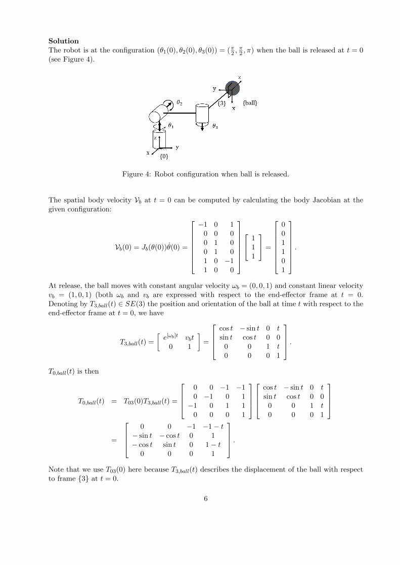
SolutionThe robot is at the configuration (θ1(0), θ2(0), θ3(0)) = (π2 ,
π2 , π) when the ball is released at t = 0
(see Figure 4).
Figure 4: Robot configuration when ball is released.
The spatial body velocity Vb at t = 0 can be computed by calculating the body Jacobian at thegiven configuration:
Vb(0) = Jb(θ(0))θ(0) =
−1 0 10 0 00 1 00 1 01 0 −11 0 0
1
11
=
001101
.
At release, the ball moves with constant angular velocity ωb = (0, 0, 1) and constant linear velocityvb = (1, 0, 1) (both ωb and vb are expressed with respect to the end-effector frame at t = 0.Denoting by T3,ball(t) ∈ SE(3) the position and orientation of the ball at time t with respect to theend-effector frame at t = 0, we have
T3,ball(t) =
[e[ωb]t vbt
0 1
]=
cos t − sin t 0 tsin t cos t 0 0
0 0 1 t0 0 0 1
.T0,ball(t) is then
T0,ball(t) = T03(0)T3,ball(t) =
0 0 −1 −10 −1 0 1−1 0 1 1
0 0 0 1
cos t − sin t 0 tsin t cos t 0 0
0 0 1 t0 0 0 1
=
0 0 −1 −1− t
− sin t − cos t 0 1− cos t sin t 0 1− t
0 0 0 1
.Note that we use T03(0) here because T3,ball(t) describes the displacement of the ball with respectto frame {3} at t = 0.
6

Problem 4 (30 points)Figure 5(a) shows the Staubli 6R robot, with its zero configuration shown in Figure 5(b).(a) Draw appropriate link reference frames, and derive the Denavit-Hartenberg parameters for thefirst three joints only.(b) The forward kinematics can be expressed in the form
T06(θ) = e[S1]θ1e[S2]θ2e[S3]θ3e[S4]θ4M4e[S5]θ5e[S6]θ6M6.
Find M4, M6, and the Si, i = 1, . . . , 6.(c) Letting T46 = e[S5]θ5e[S6]θ6M6, find T46T
−146 .
(a) 6R open chain robot, tx40.
(b) Frame assignments in zero configuration.
Figure 5: Figure for Problem 4
7
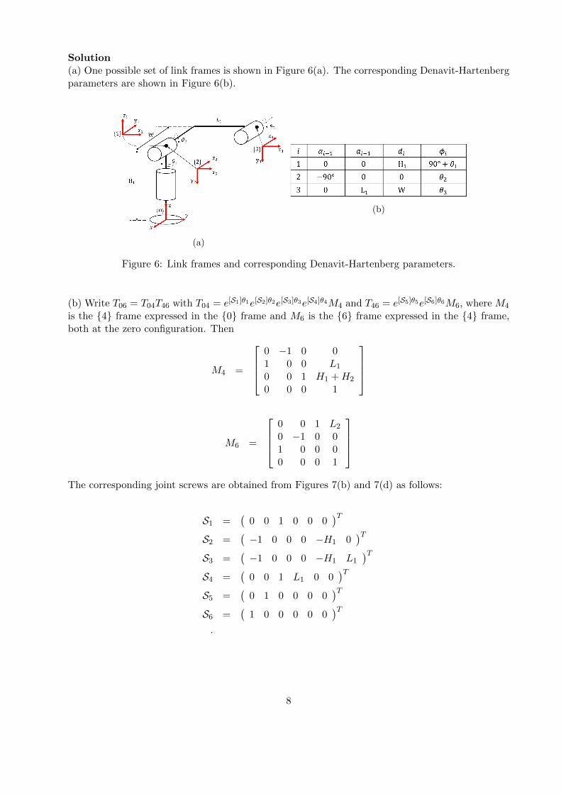
Solution(a) One possible set of link frames is shown in Figure 6(a). The corresponding Denavit-Hartenbergparameters are shown in Figure 6(b).
(a)
(b)
Figure 6: Link frames and corresponding Denavit-Hartenberg parameters.
(b) Write T06 = T04T46 with T04 = e[S1]θ1e[S2]θ2e[S3]θ3e[S4]θ4M4 and T46 = e[S5]θ5e[S6]θ6M6, where M4
is the {4} frame expressed in the {0} frame and M6 is the {6} frame expressed in the {4} frame,both at the zero configuration. Then
M4 =
0 −1 0 01 0 0 L1
0 0 1 H1 +H2
0 0 0 1
M6 =
0 0 1 L2
0 −1 0 01 0 0 00 0 0 1
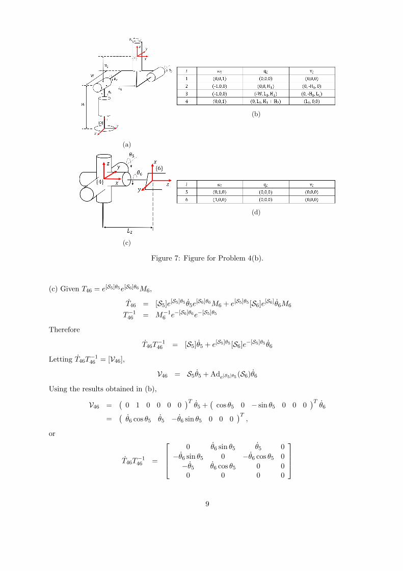
The corresponding joint screws are obtained from Figures 7(b) and 7(d) as follows:
S1 =(
0 0 1 0 0 0)T
S2 =(−1 0 0 0 −H1 0
)TS3 =
(−1 0 0 0 −H1 L1
)TS4 =
(0 0 1 L1 0 0
)TS5 =
(0 1 0 0 0 0
)TS6 =
(1 0 0 0 0 0
)T.
8
(a)
(b)
(c)
(d)
Figure 7: Figure for Problem 4(b).
(c) Given T46 = e[S5]θ5e[S6]θ6M6,
T46 = [S5]e[S5]θ5 θ5e[S6]θ6M6 + e[S5]θ5 [S6]e[S6]θ6M6
T−146 = M−16 e−[S6]θ6e−[S5]θ5
Therefore
T46T−146 = [S5]θ5 + e[S5]θ5 [S6]e−[S5]θ5 θ6
Letting T46T−146 = [V46],
V46 = S5θ5 + Ade[S5]θ5 (S6)θ6
Using the results obtained in (b),
V46 =(
0 1 0 0 0 0)Tθ5 +
(cos θ5 0 − sin θ5 0 0 0
)Tθ6
=(θ6 cos θ5 θ5 −θ6 sin θ5 0 0 0
)T,
or
T46T−146 =
0 θ6 sin θ5 θ5 0
−θ6 sin θ5 0 −θ6 cos θ5 0
−θ5 θ6 cos θ5 0 00 0 0 0
9
M2794.0027 Introduction to RoboticsFinal Examination
6-9 PM, June 5, 2020CLOSED BOOK, CLOSED NOTES
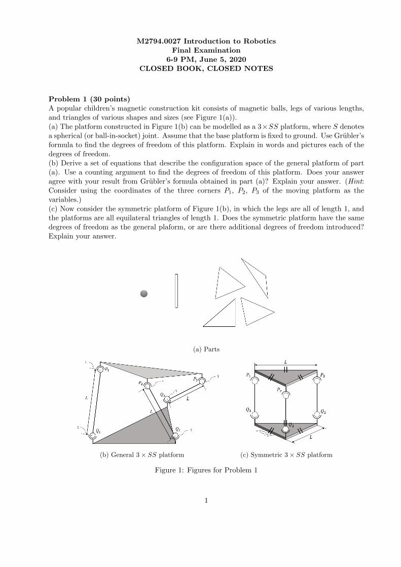
Problem 1 (30 points)A popular children’s magnetic construction kit consists of magnetic balls, legs of various lengths,and triangles of various shapes and sizes (see Figure 1(a)).(a) The platform constructed in Figure 1(b) can be modelled as a 3×SS platform, where S denotesa spherical (or ball-in-socket) joint. Assume that the base platform is fixed to ground. Use Grubler’sformula to find the degrees of freedom of this platform. Explain in words and pictures each of thedegrees of freedom.(b) Derive a set of equations that describe the configuration space of the general platform of part(a). Use a counting argument to find the degrees of freedom of this platform. Does your answeragree with your result from Grubler’s formula obtained in part (a)? Explain your answer. (Hint:Consider using the coordinates of the three corners P1, P2, P3 of the moving platform as thevariables.)(c) Now consider the symmetric platform of Figure 1(b), in which the legs are all of length 1, andthe platforms are all equilateral triangles of length 1. Does the symmetric platform have the samedegrees of freedom as the general plaform, or are there additional degrees of freedom introduced?Explain your answer.
(a) Parts
(b) General 3× SS platform (c) Symmetric 3× SS platform
Figure 1: Figures for Problem 1
1
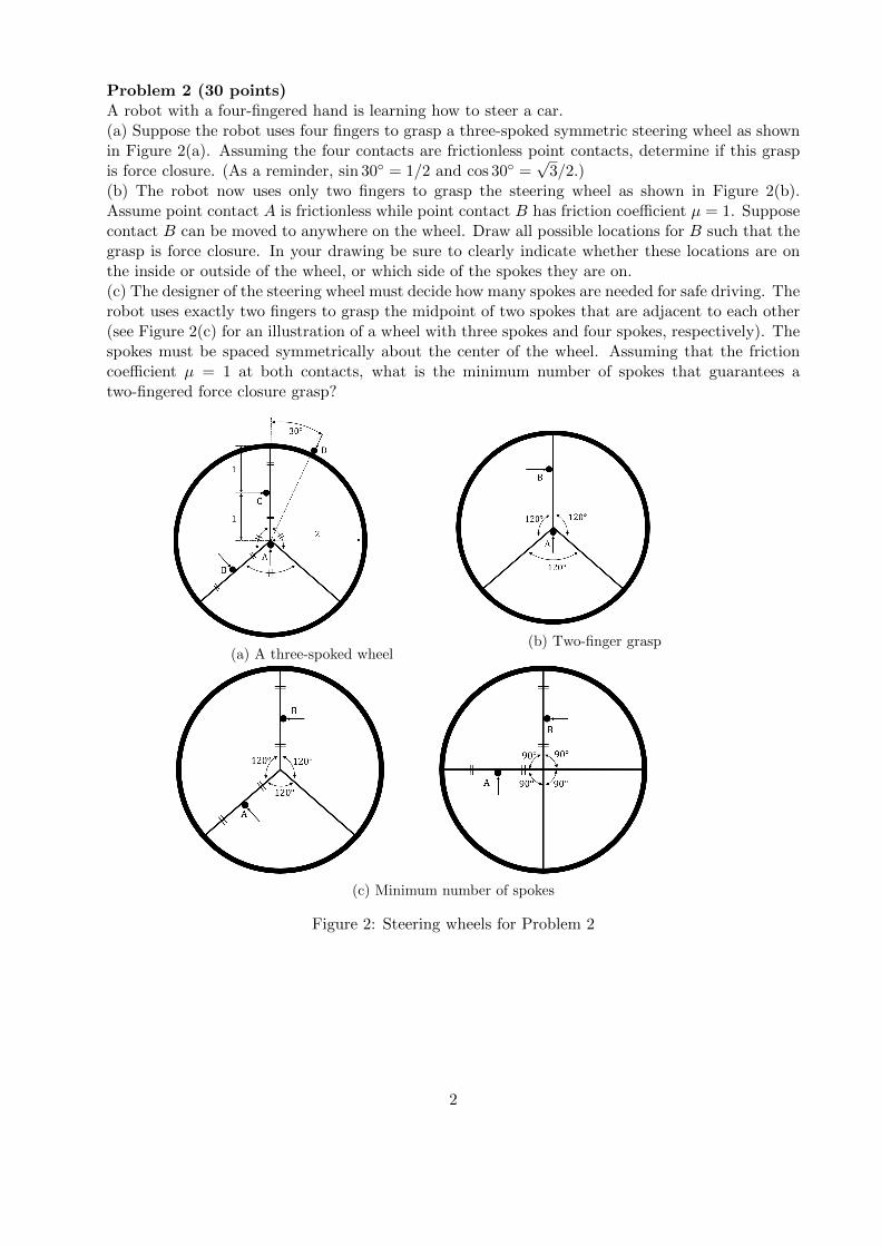
Problem 2 (30 points)A robot with a four-fingered hand is learning how to steer a car.(a) Suppose the robot uses four fingers to grasp a three-spoked symmetric steering wheel as shownin Figure 2(a). Assuming the four contacts are frictionless point contacts, determine if this graspis force closure. (As a reminder, sin 30◦ = 1/2 and cos 30◦ =
√3/2.)
(b) The robot now uses only two fingers to grasp the steering wheel as shown in Figure 2(b).Assume point contact A is frictionless while point contact B has friction coefficient µ = 1. Supposecontact B can be moved to anywhere on the wheel. Draw all possible locations for B such that thegrasp is force closure. In your drawing be sure to clearly indicate whether these locations are onthe inside or outside of the wheel, or which side of the spokes they are on.(c) The designer of the steering wheel must decide how many spokes are needed for safe driving. Therobot uses exactly two fingers to grasp the midpoint of two spokes that are adjacent to each other(see Figure 2(c) for an illustration of a wheel with three spokes and four spokes, respectively). Thespokes must be spaced symmetrically about the center of the wheel. Assuming that the frictioncoefficient µ = 1 at both contacts, what is the minimum number of spokes that guarantees atwo-fingered force closure grasp?
(a) A three-spoked wheel(b) Two-finger grasp
(c) Minimum number of spokes
Figure 2: Steering wheels for Problem 2
2

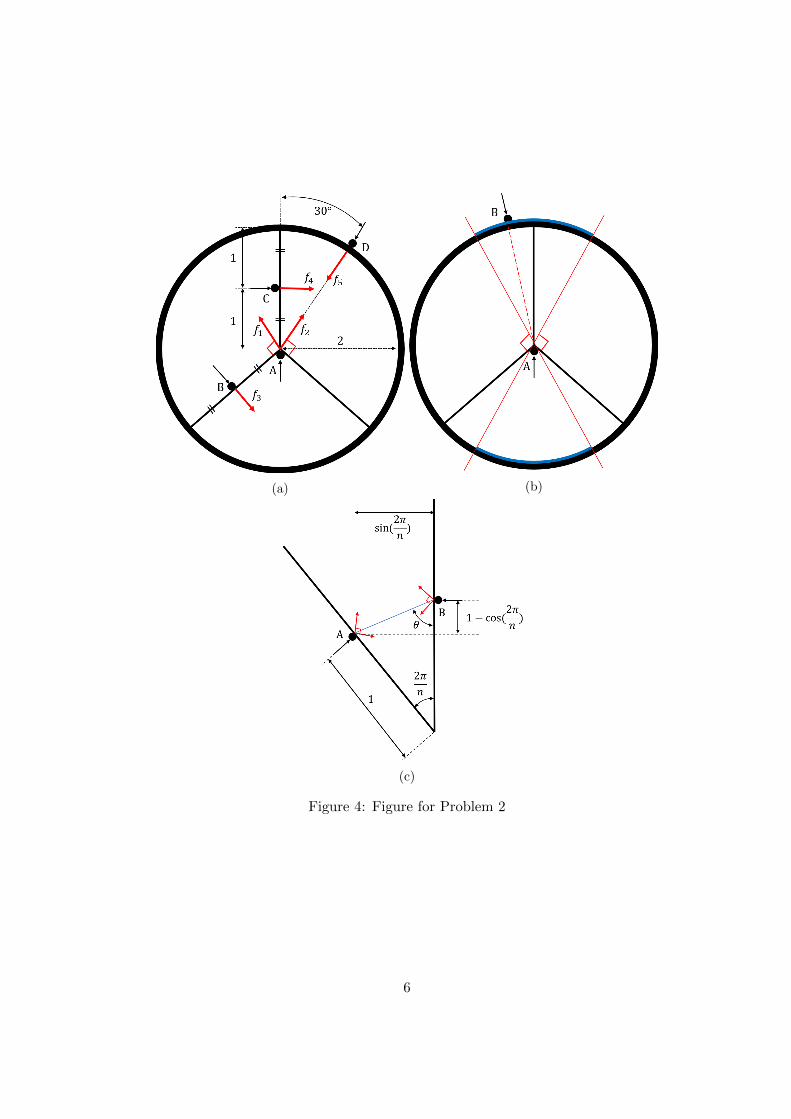
Problem 3 (30 points)DJI Robomasters is a popular robot competition in which teams of wheeled mobile robots anddrones cooperate to shoot down moving targets. Referring to Figure 3, let {s} be the fixed frame,{r} be a frame attached to the wheeled mobile robot, {c} be a frame attached to the robot cannon,{d} be a frame attached to the drone, and {t} be a frame attached to the target.(a) Let Rsr(t) ∈ SO(3) and psr(t) ∈ R3 be the orientation and position of the robot frame {r} withrespect to the fixed frame {s}. The robot is being escorted by a drone that rotates at 1 rad/secabout the z-axis of the robot {r} frame. Suppose the orientation Rsd(0) and position psd(0) of thedrone at time t = 0 are known. Find Rsd(t) and psd(t) as a function of time t.(b) Now suppose that the drone also slowly rotates about its own {d} frame z-axis at a rate of-1 rad/sec while circling the robot as explained in part (a). Suppose the orientation Rsd(0) andposition psd(0) of the drone at time t = 0 are known. Find Rsd(t) and psd(t) as a function of timet.(c) The robot now uses its cannon to fire a ball at the target frame {t}. Let {b} be a frame attachedto the ball, and let the motion of {b} be given by
Tcb =
[I pcb0 1
]∈ SE(3), pcb = (0, 0, t), t ≥ 0.
Suppose the target is described by the ellipsoid x2+y2+4z2 ≤ 1 in frame {t} coordinates. Determinewhether the ball hits the target when the motions of the cannon and target frame are given by
Tsc =
1 0 0 00 − 1√
21√2
0
0 − 1√2− 1√
2
√2
0 0 0 1
, Tst =
1√2− 1√
20
√2t
1√2
1√2
0 0
0 0 1 − 1√2t+ 3
√2
0 0 0 1
.
Figure 3: Figure for Problem 1.
3
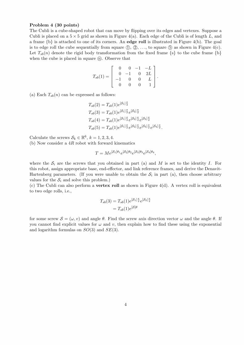
Problem 4 (30 points)The Cubli is a cube-shaped robot that can move by flipping over its edges and vertexes. Suppose aCubli is placed on a 5× 5 grid as shown in Figure 4(a). Each edge of the Cubli is of length L, anda frame {b} is attached to one of its corners. An edge roll is illustrated in Figure 4(b). The goalis to edge roll the cube sequentially from square 1©, 2©, . . ., to square 5© as shown in Figure 4(c).Let Tsb(n) denote the rigid body transformation from the fixed frame {s} to the cube frame {b}when the cube is placed in square n©. Observe that
Tsb(1) =
0 0 −1 −L0 −1 0 2L−1 0 0 L
0 0 0 1
.(a) Each Tsb(n) can be expressed as follows:
Tsb(2) = Tsb(1)e[S1]π2
Tsb(3) = Tsb(1)e[S1]π2 e[S2]
π2
Tsb(4) = Tsb(1)e[S1]π2 e[S2]
π2 e[S3]
π2
Tsb(5) = Tsb(1)e[S1]π2 e[S2]
π2 e[S3]
π2 e[S4]
π2 .
Calculate the screws Sk ∈ R6, k = 1, 2, 3, 4.(b) Now consider a 4R robot with forward kinematics
T = Me[S1]θ1e[S2]θ2e[S3]θ3e[S4]θ4 ,
where the Si are the screws that you obtained in part (a) and M is set to the identity I. Forthis robot, assign appropriate base, end-effector, and link reference frames, and derive the Denavit-Hartenberg parameters. (If you were unable to obtain the Si in part (a), then choose arbitraryvalues for the Si and solve this problem.)(c) The Cubli can also perform a vertex roll as shown in Figure 4(d). A vertex roll is equivalentto two edge rolls, i.e.,
Tsb(3) = Tsb(1)e[S1]π2 e[S2]
π2
= Tsb(1)e[S]θ
for some screw S = (ω, v) and angle θ. Find the screw axis direction vector ω and the angle θ. Ifyou cannot find explicit values for ω and v, then explain how to find these using the exponentialand logarithm formulas on SO(3) and SE(3).
4

(a)
(b)
(c)
(d)
Figure 4
5
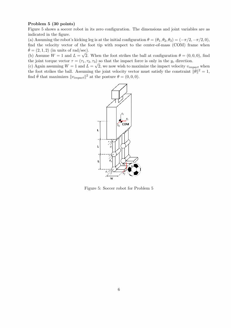
Problem 5 (30 points)Figure 5 shows a soccer robot in its zero configuration. The dimensions and joint variables are asindicated in the figure.(a) Assuming the robot’s kicking leg is at the initial configuration θ = (θ1, θ2, θ3) = (−π/2,−π/2, 0),find the velocity vector of the foot tip with respect to the center-of-mass (COM) frame whenθ = (2, 1, 2) (in units of rad/sec).(b) Assume W = 1 and L =
√2. When the foot strikes the ball at configuration θ = (0, 0, 0), find
the joint torque vector τ = (τ1, τ2, τ3) so that the impact force is only in the yc direction.(c) Again assuming W = 1 and L =
√2, we now wish to maximize the impact velocity vimpact when
the foot strikes the ball. Assuming the joint velocity vector must satisfy the constraint ‖θ‖2 = 1,find θ that maximizes ‖vimpact‖2 at the posture θ = (0, 0, 0).
Figure 5: Soccer robot for Problem 5
6
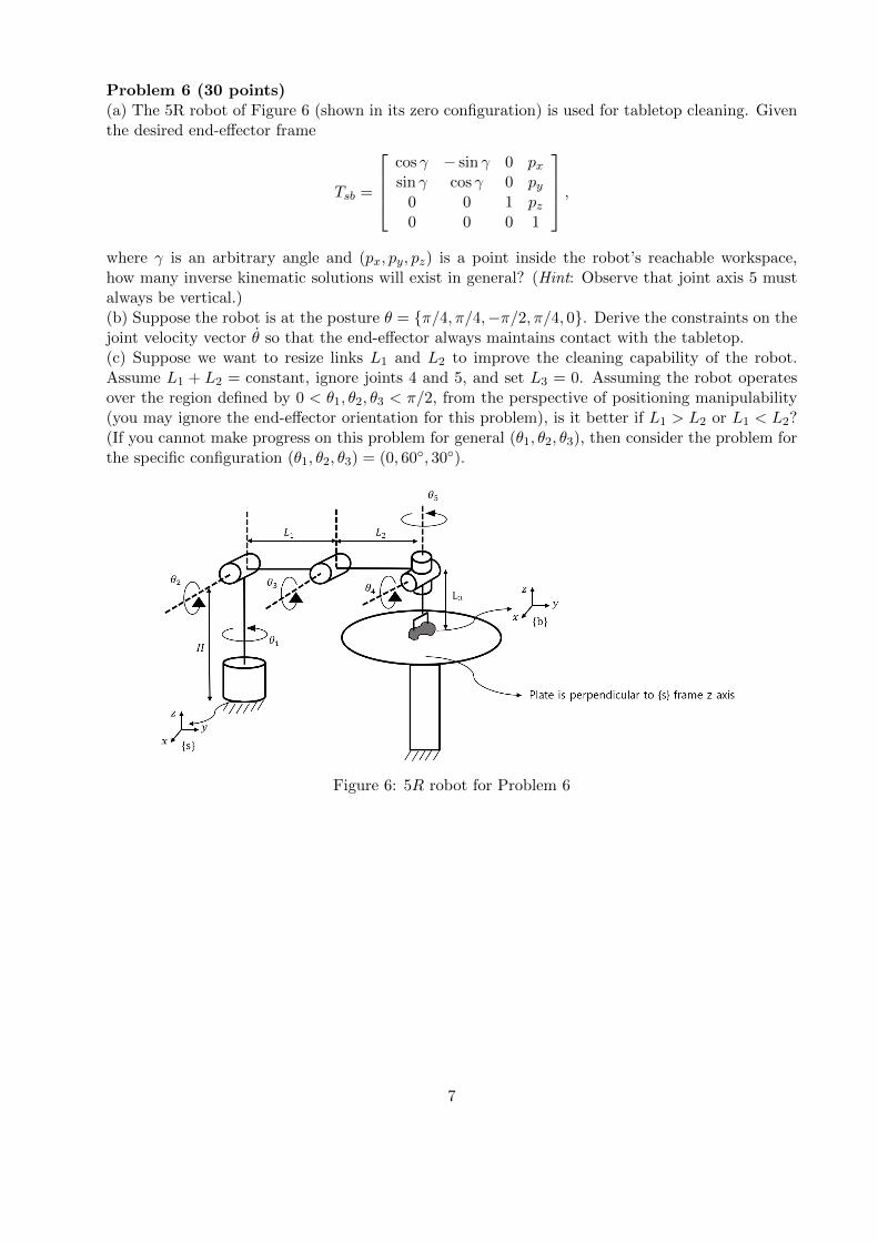
Problem 6 (30 points)(a) The 5R robot of Figure 6 (shown in its zero configuration) is used for tabletop cleaning. Giventhe desired end-effector frame
Tsb =
cos γ − sin γ 0 pxsin γ cos γ 0 py
0 0 1 pz0 0 0 1
,where γ is an arbitrary angle and (px, py, pz) is a point inside the robot’s reachable workspace,how many inverse kinematic solutions will exist in general? (Hint: Observe that joint axis 5 mustalways be vertical.)(b) Suppose the robot is at the posture θ = {π/4, π/4,−π/2, π/4, 0}. Derive the constraints on thejoint velocity vector θ so that the end-effector always maintains contact with the tabletop.(c) Suppose we want to resize links L1 and L2 to improve the cleaning capability of the robot.Assume L1 + L2 = constant, ignore joints 4 and 5, and set L3 = 0. Assuming the robot operatesover the region defined by 0 < θ1, θ2, θ3 < π/2, from the perspective of positioning manipulability(you may ignore the end-effector orientation for this problem), is it better if L1 > L2 or L1 < L2?(If you cannot make progress on this problem for general (θ1, θ2, θ3), then consider the problem forthe specific configuration (θ1, θ2, θ3) = (0, 60◦, 30◦).
Figure 6: 5R robot for Problem 6
7

M2794.0027 Introduction to RoboticsFinal Examination Solutions
6-9 PM, June 5, 2020CLOSED BOOK, CLOSED NOTES
Problem 1 (30 points)A popular children’s magnetic construction kit consists of magnetic balls, legs of various lengths,and triangles of various shapes and sizes (see Figure 2(a)).(a) The platform constructed in Figure 2(b) can be modelled as a 3×SS platform, where S denotesa spherical (or ball-in-socket) joint. Assume that the base platform is fixed to ground. Use Grubler’sformula to find the degrees of freedom of this platform. Explain in words and pictures each of thedegrees of freedom.(b) Derive a set of equations that describe the configuration space of the general platform of part(a). Use a counting argument to find the degrees of freedom of this platform. Does your answeragree with your result from Grubler’s formula obtained in part (a)? Explain your answer. (Hint:Consider using the coordinates of the three corners P1, P2, P3 of the moving platform as thevariables.)(c) Now consider the symmetric platform of Figure 2(b), in which the legs are all of length 1, andthe platforms are all equilateral triangles of length 1. Does the symmetric platform have the samedegrees of freedom as the general plaform, or are there additional degrees of freedom introduced?Explain your answer.
(a) Parts
(b) General 3× SS platform (c) Symmetric 3× SS platform
Figure 1: Figures for Problem 1
1
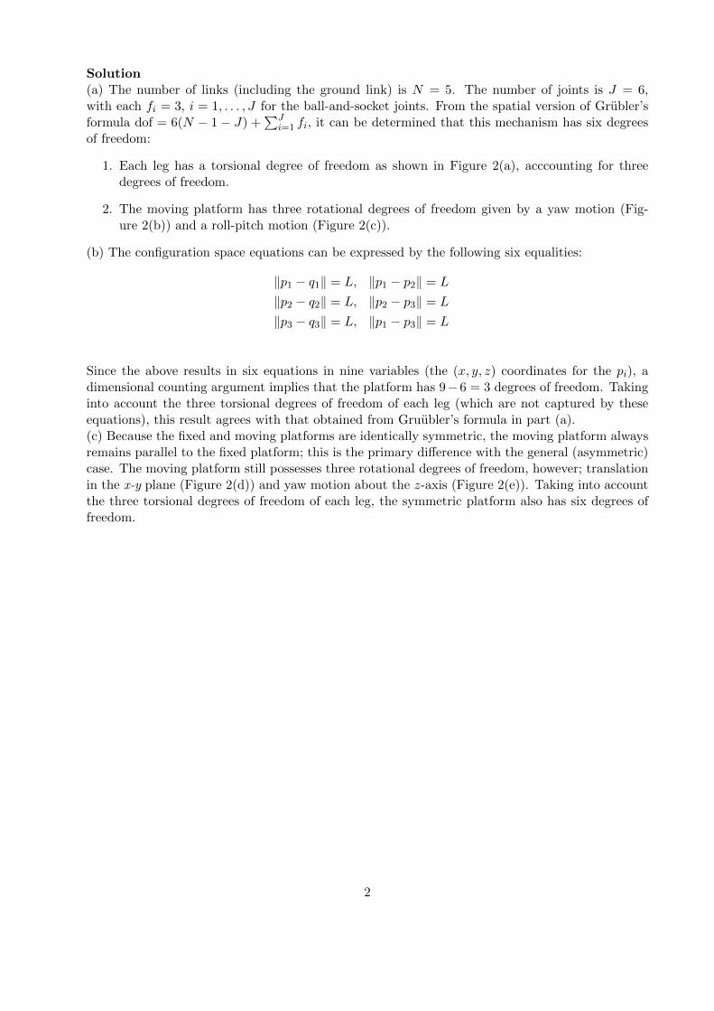
Solution(a) The number of links (including the ground link) is N = 5. The number of joints is J = 6,with each fi = 3, i = 1, . . . , J for the ball-and-socket joints. From the spatial version of Grubler’sformula dof = 6(N − 1 − J) +
∑Ji=1 fi, it can be determined that this mechanism has six degrees
of freedom:
1. Each leg has a torsional degree of freedom as shown in Figure 2(a), acccounting for threedegrees of freedom.
2. The moving platform has three rotational degrees of freedom given by a yaw motion (Fig-ure 2(b)) and a roll-pitch motion (Figure 2(c)).
(b) The configuration space equations can be expressed by the following six equalities:
‖p1 − q1‖ = L, ‖p1 − p2‖ = L
‖p2 − q2‖ = L, ‖p2 − p3‖ = L
‖p3 − q3‖ = L, ‖p1 − p3‖ = L
Since the above results in six equations in nine variables (the (x, y, z) coordinates for the pi), adimensional counting argument implies that the platform has 9− 6 = 3 degrees of freedom. Takinginto account the three torsional degrees of freedom of each leg (which are not captured by theseequations), this result agrees with that obtained from Gruubler’s formula in part (a).(c) Because the fixed and moving platforms are identically symmetric, the moving platform alwaysremains parallel to the fixed platform; this is the primary difference with the general (asymmetric)case. The moving platform still possesses three rotational degrees of freedom, however; translationin the x-y plane (Figure 2(d)) and yaw motion about the z-axis (Figure 2(e)). Taking into accountthe three torsional degrees of freedom of each leg, the symmetric platform also has six degrees offreedom.
2
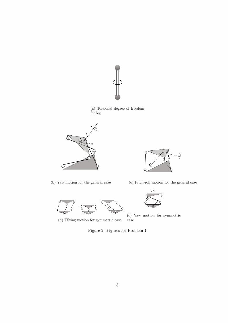
(a) Torsional degree of freedomfor leg
(b) Yaw motion for the general case (c) Pitch-roll motion for the general case
(d) Tilting motion for symmetric case(e) Yaw motion for symmetriccase
Figure 2: Figures for Problem 1
3

Problem 2 (30 points)A robot with a four-fingered hand is learning how to steer a car.(a) Suppose the robot uses four fingers to grasp a three-spoked symmetric steering wheel as shownin Figure 3(a). Assuming the four contacts are frictionless point contacts, determine if this graspis force closure. (As a reminder, sin 30◦ = 1/2 and cos 30◦ =
√3/2.)
(b) The robot now uses only two fingers to grasp the steering wheel as shown in Figure 3(b).Assume point contact A is frictionless while point contact B has friction coefficient µ = 1. Supposecontact B can be moved to anywhere on the wheel. Draw all possible locations for B such that thegrasp is force closure. In your drawing be sure to clearly indicate whether these locations are onthe inside or outside of the wheel, or which side of the spokes they are on.(c) The designer of the steering wheel must decide how many spokes are needed for safe driving. Therobot uses exactly two fingers to grasp the midpoint of two spokes that are adjacent to each other(see Figure 3(c) for an illustration of a wheel with three spokes and four spokes, respectively). Thespokes must be spaced symmetrically about the center of the wheel. Assuming that the frictioncoefficient µ = 1 at both contacts, what is the minimum number of spokes that guarantees atwo-fingered force closure grasp?
(a) A three-spoked wheel(b) Two-finger grasp
(c) Minimum number of spokes
Figure 3: Steering wheels for Problem 2
4
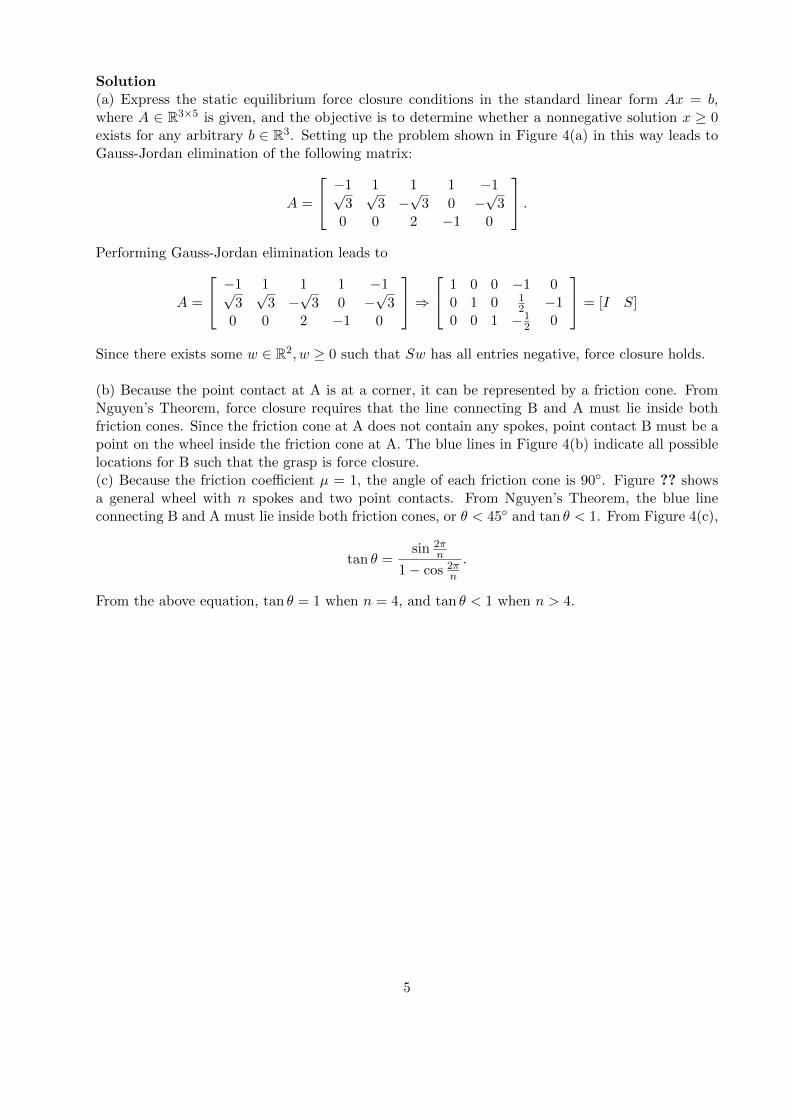
Solution(a) Express the static equilibrium force closure conditions in the standard linear form Ax = b,where A ∈ R3×5 is given, and the objective is to determine whether a nonnegative solution x ≥ 0exists for any arbitrary b ∈ R3. Setting up the problem shown in Figure 4(a) in this way leads toGauss-Jordan elimination of the following matrix:
A =
−1 1 1 1 −1√3√
3 −√
3 0 −√
30 0 2 −1 0
.Performing Gauss-Jordan elimination leads to
A =
−1 1 1 1 −1√3√
3 −√
3 0 −√
30 0 2 −1 0
⇒ 1 0 0 −1 0
0 1 0 12 −1
0 0 1 −12 0
= [I S]
Since there exists some w ∈ R2, w ≥ 0 such that Sw has all entries negative, force closure holds.
(b) Because the point contact at A is at a corner, it can be represented by a friction cone. FromNguyen’s Theorem, force closure requires that the line connecting B and A must lie inside bothfriction cones. Since the friction cone at A does not contain any spokes, point contact B must be apoint on the wheel inside the friction cone at A. The blue lines in Figure 4(b) indicate all possiblelocations for B such that the grasp is force closure.(c) Because the friction coefficient µ = 1, the angle of each friction cone is 90◦. Figure ?? showsa general wheel with n spokes and two point contacts. From Nguyen’s Theorem, the blue lineconnecting B and A must lie inside both friction cones, or θ < 45◦ and tan θ < 1. From Figure 4(c),
tan θ =sin 2π
n
1− cos 2πn
.
From the above equation, tan θ = 1 when n = 4, and tan θ < 1 when n > 4.
5
(a) (b)
(c)
Figure 4: Figure for Problem 2
6
Problem 3 (30 points)DJI Robomasters is a popular robot competition in which teams of wheeled mobile robots anddrones cooperate to shoot down moving targets. Referring to Figure 5, let {s} be the fixed frame,{r} be a frame attached to the wheeled mobile robot, {c} be a frame attached to the robot cannon,{d} be a frame attached to the drone, and {t} be a frame attached to the target.(a) Let Rsr(t) ∈ SO(3) and psr(t) ∈ R3 be the orientation and position of the robot frame {r} withrespect to the fixed frame {s}. The robot is being escorted by a drone that rotates at 1 rad/secabout the z-axis of the robot {r} frame. Suppose the orientation Rsd(0) and position psd(0) of thedrone at time t = 0 are known. Find Rsd(t) and psd(t) as a function of time t.(b) Now suppose that the drone also slowly rotates about its own {d} frame z-axis at a rate of-1 rad/sec while circling the robot as explained in part (a). Suppose the orientation Rsd(0) andposition psd(0) of the drone at time t = 0 are known. Find Rsd(t) and psd(t) as a function of timet.(c) The robot now uses its cannon to fire a ball at the target frame {t}. Let {b} be a frame attachedto the ball, and let the motion of {b} be given by
Tcb =
[I pcb0 1
]∈ SE(3), pcb = (0, 0, t), t ≥ 0.
Suppose the target is described by the ellipsoid x2+y2+4z2 ≤ 1 in frame {t} coordinates. Determinewhether the ball hits the target when the motions of the cannon and target frame are given by
Tsc =
1 0 0 00 − 1√
21√2
0
0 − 1√2− 1√
2
√2
0 0 0 1
, Tst =
1√2− 1√
20
√2t
1√2
1√2
0 0
0 0 1 − 1√2t+ 3
√2
0 0 0 1
.
Figure 5: Figure for Problem 1.
7
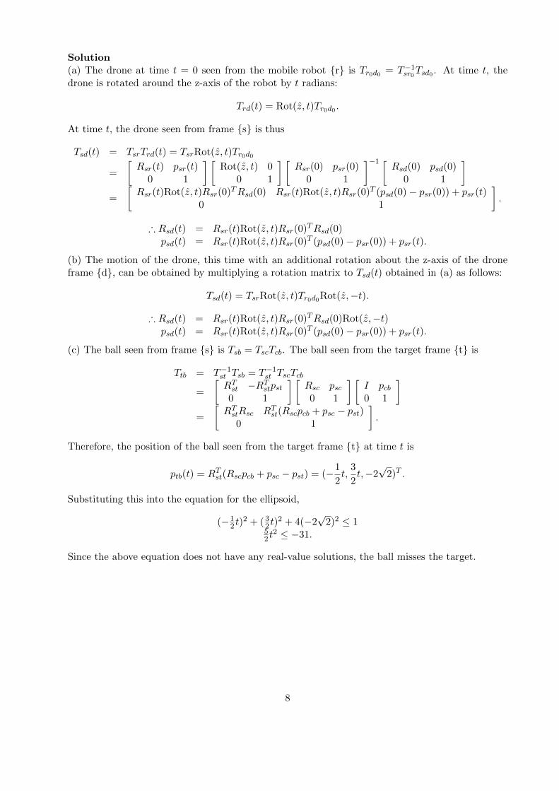
Solution(a) The drone at time t = 0 seen from the mobile robot {r} is Tr0d0 = T−1sr0Tsd0 . At time t, thedrone is rotated around the z-axis of the robot by t radians:
Trd(t) = Rot(z, t)Tr0d0 .
At time t, the drone seen from frame {s} is thus
Tsd(t) = TsrTrd(t) = TsrRot(z, t)Tr0d0
=
[Rsr(t) psr(t)
0 1
] [Rot(z, t) 0
0 1
] [Rsr(0) psr(0)
0 1
]−1 [Rsd(0) psd(0)
0 1
]=
[Rsr(t)Rot(z, t)Rsr(0)TRsd(0) Rsr(t)Rot(z, t)Rsr(0)T (psd(0)− psr(0)) + psr(t)
0 1
].
∴ Rsd(t) = Rsr(t)Rot(z, t)Rsr(0)TRsd(0)psd(t) = Rsr(t)Rot(z, t)Rsr(0)T (psd(0)− psr(0)) + psr(t).
(b) The motion of the drone, this time with an additional rotation about the z-axis of the droneframe {d}, can be obtained by multiplying a rotation matrix to Tsd(t) obtained in (a) as follows:
Tsd(t) = TsrRot(z, t)Tr0d0Rot(z,−t).
∴ Rsd(t) = Rsr(t)Rot(z, t)Rsr(0)TRsd(0)Rot(z,−t)psd(t) = Rsr(t)Rot(z, t)Rsr(0)T (psd(0)− psr(0)) + psr(t).
(c) The ball seen from frame {s} is Tsb = TscTcb. The ball seen from the target frame {t} is
Ttb = T−1st Tsb = T−1st TscTcb
=
[RTst −RTstpst0 1
] [Rsc psc0 1
] [I pcb0 1
]=
[RTstRsc RTst(Rscpcb + psc − pst)
0 1
].
Therefore, the position of the ball seen from the target frame {t} at time t is
ptb(t) = RTst(Rscpcb + psc − pst) = (−1
2t,
3
2t,−2
√2)T .
Substituting this into the equation for the ellipsoid,
(−12 t)
2 + (32 t)2 + 4(−2
√2)2 ≤ 1
52 t
2 ≤ −31.
Since the above equation does not have any real-value solutions, the ball misses the target.
8

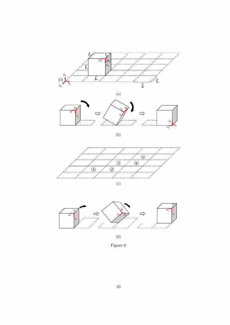
Problem 4 (30 points)The Cubli is a cube-shaped robot that can move by flipping over its edges and vertexes. Suppose aCubli is placed on a 5× 5 grid as shown in Figure 6(a). Each edge of the Cubli is of length L, anda frame {b} is attached to one of its corners. An edge roll is illustrated in Figure 6(b). The goalis to edge roll the cube sequentially from square 1©, 2©, . . ., to square 5© as shown in Figure 6(c).Let Tsb(n) denote the rigid body transformation from the fixed frame {s} to the cube frame {b}when the cube is placed in square n©. Observe that
Tsb(1) =
0 0 −1 −L0 −1 0 2L−1 0 0 L
0 0 0 1
.(a) Each Tsb(n) can be expressed as follows:
Tsb(2) = Tsb(1)e[S1]π2
Tsb(3) = Tsb(1)e[S1]π2 e[S2]
π2
Tsb(4) = Tsb(1)e[S1]π2 e[S2]
π2 e[S3]
π2
Tsb(5) = Tsb(1)e[S1]π2 e[S2]
π2 e[S3]
π2 e[S4]
π2 .
Calculate the screws Sk ∈ R6, k = 1, 2, 3, 4.(b) Now consider a 4R robot with forward kinematics
T = Me[S1]θ1e[S2]θ2e[S3]θ3e[S4]θ4 ,
where the Si are the screws that you obtained in part (a) and M is set to the identity I. Forthis robot, assign appropriate base, end-effector, and link reference frames, and derive the Denavit-Hartenberg parameters. (If you were unable to obtain the Si in part (a), then choose arbitraryvalues for the Si and solve this problem.)(c) The Cubli can also perform a vertex roll as shown in Figure 6(d). A vertex roll is equivalentto two edge rolls, i.e.,
Tsb(3) = Tsb(1)e[S1]π2 e[S2]
π2
= Tsb(1)e[S]θ
for some screw S = (ω, v) and angle θ. Find the screw axis direction vector ω and the angle θ. Ifyou cannot find explicit values for ω and v, then explain how to find these using the exponentialand logarithm formulas on SO(3) and SE(3).
9
(a)
(b)
(c)
(d)
Figure 6
10
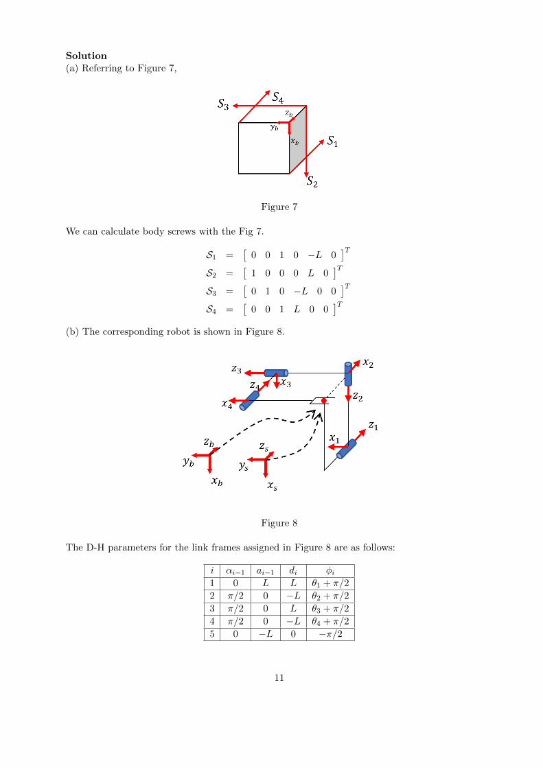
Solution(a) Referring to Figure 7,
Figure 7
We can calculate body screws with the Fig 7.
S1 =[
0 0 1 0 −L 0]T
S2 =[
1 0 0 0 L 0]T
S3 =[
0 1 0 −L 0 0]T
S4 =[
0 0 1 L 0 0]T
(b) The corresponding robot is shown in Figure 8.
Figure 8
The D-H parameters for the link frames assigned in Figure 8 are as follows:
i αi−1 ai−1 di φi1 0 L L θ1 + π/2
2 π/2 0 −L θ2 + π/2
3 π/2 0 L θ3 + π/2
4 π/2 0 −L θ4 + π/2
5 0 −L 0 −π/2
11
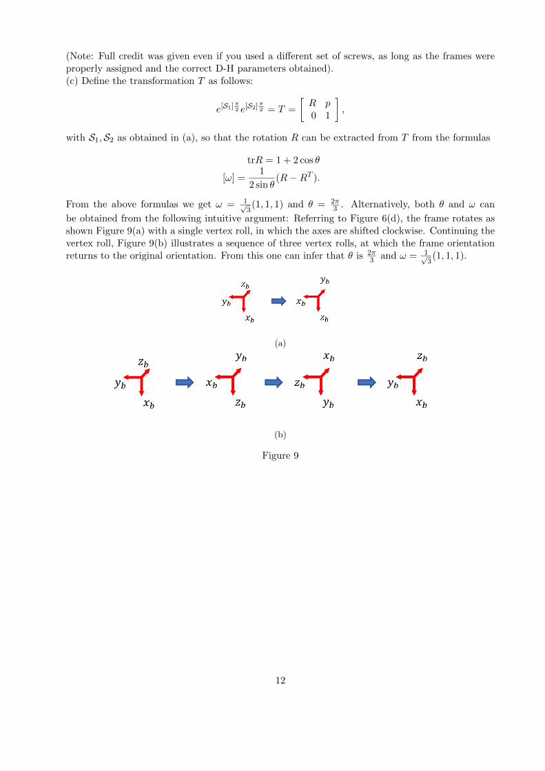
(Note: Full credit was given even if you used a different set of screws, as long as the frames wereproperly assigned and the correct D-H parameters obtained).(c) Define the transformation T as follows:
e[S1]π2 e[S2]
π2 = T =
[R p0 1
],
with S1,S2 as obtained in (a), so that the rotation R can be extracted from T from the formulas
trR = 1 + 2 cos θ
[ω] =1
2 sin θ(R−RT ).
From the above formulas we get ω = 1√3(1, 1, 1) and θ = 2π
3 . Alternatively, both θ and ω can
be obtained from the following intuitive argument: Referring to Figure 6(d), the frame rotates asshown Figure 9(a) with a single vertex roll, in which the axes are shifted clockwise. Continuing thevertex roll, Figure 9(b) illustrates a sequence of three vertex rolls, at which the frame orientationreturns to the original orientation. From this one can infer that θ is 2π
3 and ω = 1√3(1, 1, 1).
(a)
(b)
Figure 9
12

Problem 5 (30 points)Figure 5 shows a soccer robot in its zero configuration. The dimensions and joint variables are asindicated in the figure.(a) Assuming the robot’s kicking leg is at the initial configuration θ = (θ1, θ2, θ3) = (−π/2,−π/2, 0),find the velocity vector of the foot tip with respect to the center-of-mass (COM) frame whenθ = (2, 1, 2) (in units of rad/sec).(b) Assume W = 1 and L =
√2. When the foot strikes the ball at configuration θ = (0, 0, 0), find
the joint torque vector τ = (τ1, τ2, τ3) so that the impact force is only in the yc direction.(c) Again assuming W = 1 and L =
√2, we now wish to maximize the impact velocity vimpact when
the foot strikes the ball. Assuming the joint velocity vector must satisfy the constraint ‖θ‖2 = 1,find θ that maximizes ‖vimpact‖2 at the posture θ = (0, 0, 0).
Figure 10: Soccer robot for Problem 5
13
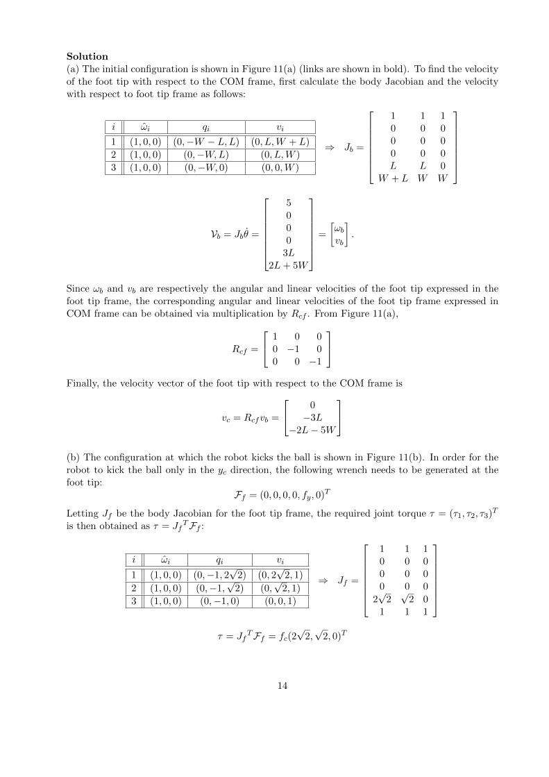
Solution(a) The initial configuration is shown in Figure 11(a) (links are shown in bold). To find the velocityof the foot tip with respect to the COM frame, first calculate the body Jacobian and the velocitywith respect to foot tip frame as follows:
i ωi qi vi
1 (1, 0, 0) (0,−W − L,L) (0, L,W + L)
2 (1, 0, 0) (0,−W,L) (0, L,W )
3 (1, 0, 0) (0,−W, 0) (0, 0,W )
⇒ Jb =
1 1 10 0 00 0 00 0 0L L 0
W + L W W
Vb = Jbθ =
5000
3L2L+ 5W
=
[ωbvb
].
Since ωb and vb are respectively the angular and linear velocities of the foot tip expressed in thefoot tip frame, the corresponding angular and linear velocities of the foot tip frame expressed inCOM frame can be obtained via multiplication by Rcf . From Figure 11(a),
Rcf =
1 0 00 −1 00 0 −1
Finally, the velocity vector of the foot tip with respect to the COM frame is
vc = Rcfvb =
0−3L
−2L− 5W
(b) The configuration at which the robot kicks the ball is shown in Figure 11(b). In order for therobot to kick the ball only in the yc direction, the following wrench needs to be generated at thefoot tip:
Ff = (0, 0, 0, 0, fy, 0)T
Letting Jf be the body Jacobian for the foot tip frame, the required joint torque τ = (τ1, τ2, τ3)T
is then obtained as τ = JfTFf :
i ωi qi vi
1 (1, 0, 0) (0,−1, 2√
2) (0, 2√
2, 1)
2 (1, 0, 0) (0,−1,√
2) (0,√
2, 1)
3 (1, 0, 0) (0,−1, 0) (0, 0, 1)
⇒ Jf =
1 1 10 0 00 0 00 0 0
2√
2√
2 01 1 1
τ = Jf
TFf = fc(2√
2,√
2, 0)T
14
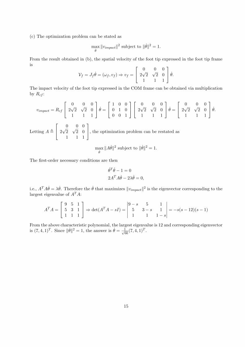
(c) The optimization problem can be stated as
maxθ‖vimpact‖2 subject to ‖θ‖2 = 1.
From the result obtained in (b), the spatial velocity of the foot tip expressed in the foot tip frameis
Vf = Jf θ = (ωf , vf )⇒ vf =
0 0 0
2√
2√
2 01 1 1
θ.The impact velocity of the foot tip expressed in the COM frame can be obtained via multiplicationby Rcf :
vimpact = Rcf
0 0 0
2√
2√
2 01 1 1
θ =
1 0 00 1 00 0 1
0 0 0
2√
2√
2 01 1 1
θ =
0 0 0
2√
2√
2 01 1 1
θ.
Letting A ,
0 0 0
2√
2√
2 01 1 1
, the optimization problem can be restated as
maxθ‖Aθ‖2 subject to ‖θ‖2 = 1.
The first-order necessary conditions are then
θT θ − 1 = 0
2ATAθ − 2λθ = 0,
i.e., ATAθ = λθ. Therefore the θ that maximizes ‖vimpact‖2 is the eigenvector corresponding to thelargest eigenvalue of ATA:
ATA =
9 5 15 3 11 1 1
⇒ det(ATA− sI) =
∣∣∣∣∣∣9− s 5 1
5 3− s 11 1 1− s
∣∣∣∣∣∣ = −s(s− 12)(s− 1)
From the above characteristic polynomial, the largest eigenvalue is 12 and corresponding eigenvectoris (7, 4, 1)T . Since ‖θ‖2 = 1, the answer is θ = 1√
66(7, 4, 1)T .
15
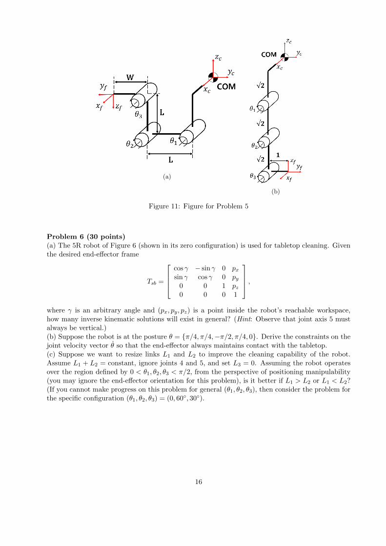
(a)
(b)
Figure 11: Figure for Problem 5
Problem 6 (30 points)(a) The 5R robot of Figure 6 (shown in its zero configuration) is used for tabletop cleaning. Giventhe desired end-effector frame
Tsb =
cos γ − sin γ 0 pxsin γ cos γ 0 py
0 0 1 pz0 0 0 1
,where γ is an arbitrary angle and (px, py, pz) is a point inside the robot’s reachable workspace,how many inverse kinematic solutions will exist in general? (Hint: Observe that joint axis 5 mustalways be vertical.)(b) Suppose the robot is at the posture θ = {π/4, π/4,−π/2, π/4, 0}. Derive the constraints on thejoint velocity vector θ so that the end-effector always maintains contact with the tabletop.(c) Suppose we want to resize links L1 and L2 to improve the cleaning capability of the robot.Assume L1 + L2 = constant, ignore joints 4 and 5, and set L3 = 0. Assuming the robot operatesover the region defined by 0 < θ1, θ2, θ3 < π/2, from the perspective of positioning manipulability(you may ignore the end-effector orientation for this problem), is it better if L1 > L2 or L1 < L2?(If you cannot make progress on this problem for general (θ1, θ2, θ3), then consider the problem forthe specific configuration (θ1, θ2, θ3) = (0, 60◦, 30◦).
16
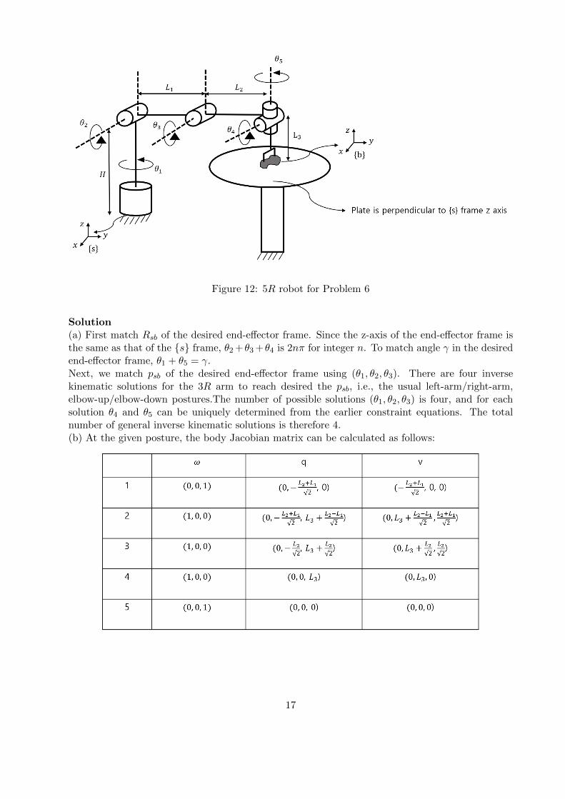
Figure 12: 5R robot for Problem 6
Solution(a) First match Rsb of the desired end-effector frame. Since the z-axis of the end-effector frame isthe same as that of the {s} frame, θ2 +θ3 +θ4 is 2nπ for integer n. To match angle γ in the desiredend-effector frame, θ1 + θ5 = γ.Next, we match psb of the desired end-effector frame using (θ1, θ2, θ3). There are four inversekinematic solutions for the 3R arm to reach desired the psb, i.e., the usual left-arm/right-arm,elbow-up/elbow-down postures.The number of possible solutions (θ1, θ2, θ3) is four, and for eachsolution θ4 and θ5 can be uniquely determined from the earlier constraint equations. The totalnumber of general inverse kinematic solutions is therefore 4.(b) At the given posture, the body Jacobian matrix can be calculated as follows:
17
Jb(θ) =
0 1 1 1 00 0 0 0 01 0 0 0 1
−L1+L2√2
0 0 0 0
0 L3 + L2−L1√2
L3 + L2√2
L3 0
0 L2+L1√2
L2√2
0 0
,
The body velocity is then given by Vb = Jb(θ)θ, and for the end-effector to maintain contact withthe tabletop, the z-axis comonent of Vb must be 0. Therefore we have L2+L1√
2θ2 + L2√
2θ3 = 0. (c) The
body Jacobian matrix can be calculated as follows:
Jb(θ) =
0 1 1s23 0 0c23 0 0
−L2c23 − L1c2 0 00 L1s3 00 L2 + L1c3 L2
,
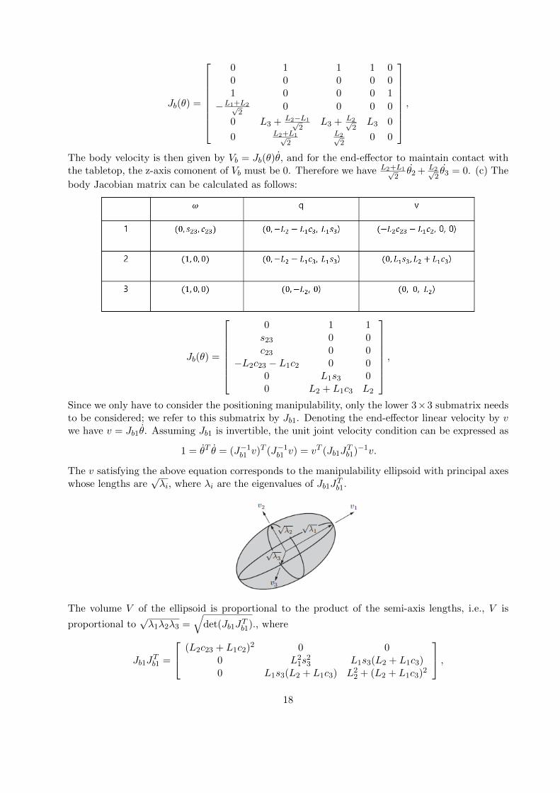
Since we only have to consider the positioning manipulability, only the lower 3×3 submatrix needsto be considered; we refer to this submatrix by Jb1. Denoting the end-effector linear velocity by vwe have v = Jb1θ. Assuming Jb1 is invertible, the unit joint velocity condition can be expressed as
1 = θT θ = (J−1b1 v)T (J−1b1 v) = vT (Jb1JTb1)−1v.
The v satisfying the above equation corresponds to the manipulability ellipsoid with principal axeswhose lengths are
√λi, where λi are the eigenvalues of Jb1J
Tb1.
The volume V of the ellipsoid is proportional to the product of the semi-axis lengths, i.e., V is
proportional to√λ1λ2λ3 =
√det(Jb1J
Tb1)., where
Jb1JTb1 =
(L2c23 + L1c2)2 0 0
0 L21s
23 L1s3(L2 + L1c3)
0 L1s3(L2 + L1c3) L22 + (L2 + L1c3)
2
,18
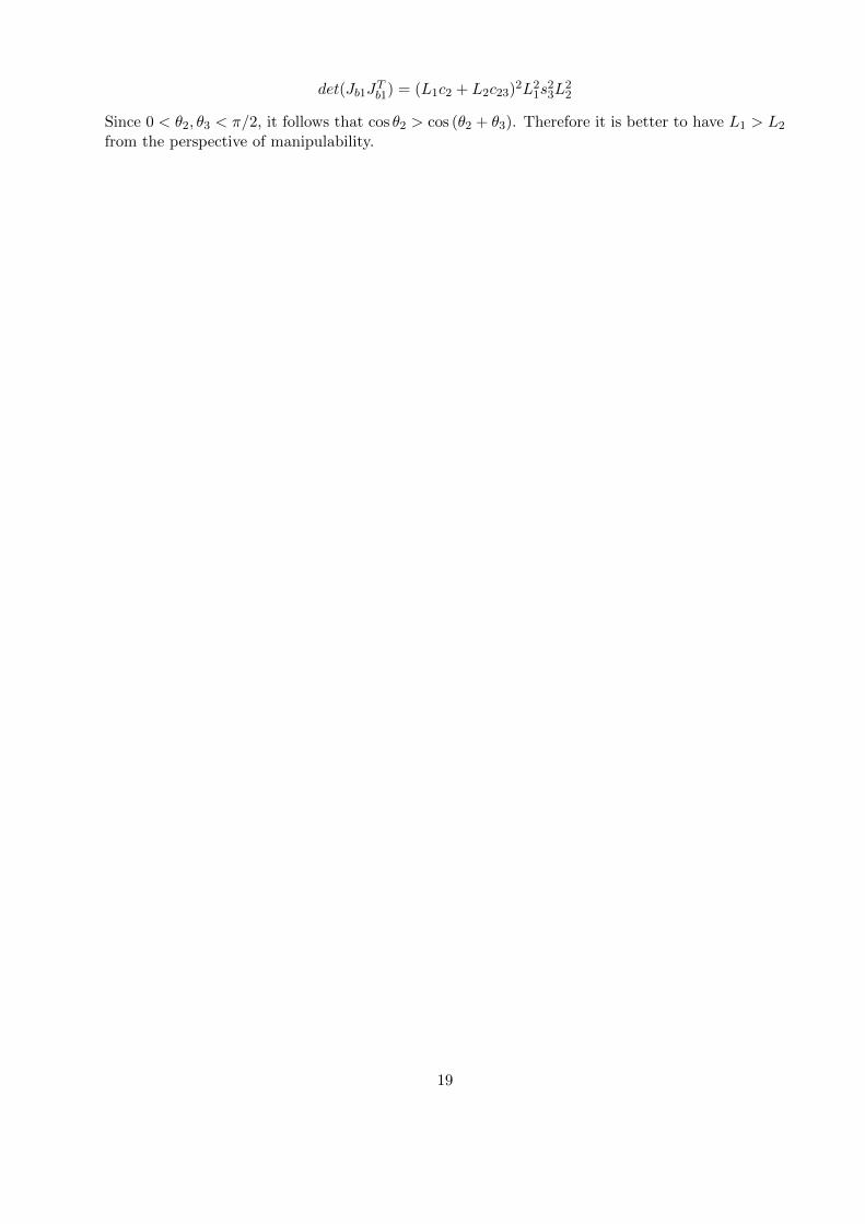
det(Jb1JTb1) = (L1c2 + L2c23)
2L21s
23L
22
Since 0 < θ2, θ3 < π/2, it follows that cos θ2 > cos (θ2 + θ3). Therefore it is better to have L1 > L2
from the perspective of manipulability.
19