Embed Size (px)
Citation preview

ZM4 Instruction Manual 9R87-IR November 2010
MM44 HHaannddhheelldd PPrreessssuurree aanndd LLoooopp CCaalliibbrraattoorr

ZM4 Instruction Manual 9R87-IR November 2010
Table of Contents
Certification and Safety...............................................................3 Product Overview ........................................................................5 Keys and Functions………………………………………………….6 Setup Menus.................................................................................8 Changing Batteries ...................................................................12 Accessing SD Card....................................................................13 Downloading Data Using USB Interface..................................14 Installing Wire Stand .................................................................15 Range Specifications..……………………………………………..16 Specifications.............................................................................18 Zeroing and Field Recalibration ...............................................22 Applications ...............................................................................23 Contact Meriam ..........................................................................26
Figures
Figure 1: Inputs and Outputs…………………………….……… 5 Figure 2: Keypad Functions…………………………….............. 6 Figure 3: Keypad Functions……………………………………… 7 Figure 4: Measure Mode Display………………………………... 8 Figure 5: Main Unit Setup Display………………………………. 9 Figure 6: Sensor Setup Display…………………………………. 10 Figure 7: VMA Setup Display…………………………………….. 11 Figure 8: Changing Batteries……………………….……………. 12 Figure 9: Accessing SD Card……………………………………. 13 Figure 10: Installing Wire Stand…………………………………... 15 Thank you for purchasing this product. Meriam has been providing innovative, reliable, cost effective measurement and calibration solutions for 100 years. The M400 Single Sensor or M402 Dual Sensor Handheld Pressure Transmitter Calibrator continues this legacy and is the first of its kind for the process measurement industry.
ZM4 Instruction Manual 9R87-IR November 2010
26
Contact Meriam
In the event an M4 requires service or must be returned for repair, please contact Meriam at the numbers listed below.
DO NOT send any unit in for repair without first contacting Meriam for a Return Material Authorization (RMA) number. If this number has not been obtained and clearly marked on the return packaging, the unit will be returned at the shipper’s expense. An RMA number will be provided by the Meriam Repair Department when you call, fax or e-mail your information. Certification for Non-Hazardous Materials will also be required. The RMA number must accompany all incoming packages to insure proper tracking, processing and repair work. To assist us in processing your repair request, please have the Model & Serial Number of the unit available when you call. This information is located on the M4 label. Information in this document is subject to change without notice. Check the Meriam web site (www.meriam.com) for the latest manual revision. For customer assistance please call your local Meriam representative or Meriam directly.
Meriam Process Technologies 10920 Madison Avenue Cleveland, Ohio 44102
Telephone: (216) 281-1100
Fax: (216) 281-0228
E-mail: [email protected] Web: www.meriam.com
ZM4 Instruction Manual 9R87-IR November 2010
3
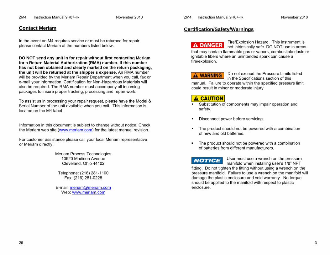
Certification/Safety/Warnings
Fire/Explosion Hazard. This instrument is not intrinsically safe. DO NOT use in areas
that may contain flammable gas or vapors, combustible dusts or ignitable fibers where an unintended spark can cause a fire/explosion.
Do not exceed the Pressure Limits listed in the Specifications section of this
manual. Failure to operate within the specified pressure limit could result in minor or moderate injury
Substitution of components may impair operation and
safety.
Disconnect power before servicing.
The product should not be powered with a combination of new and old batteries.
The product should not be powered with a combination of batteries from different manufacturers.
User must use a wrench on the pressure manifold when installing user’s 1/8” NPT
fitting. Do not tighten the fitting without using a wrench on the pressure manifold. Failure to use a wrench on the manifold will damage the plastic enclosure and void warranty No torque should be applied to the manifold with respect to plastic enclosure.

ZM4 Instruction Manual 9R87-IR November 2010
4
Safety Information
Failure to follow all instructions could result in injury. Read, understand and follow all safety warnings and instructions provided with this product. Also, meet or exceed your employer’s safety practices.
In no event shall Meriam be liable for any indirect, special, incidental, consequential or punitive damages or for any lost profits arising out of or relating to any services provided by Meriam or its affiliates. It is not possible for Meriam to identify all foreseeable uses/misuses, therefore all persons involved in commissioning, using or maintaining this product must satisfy themselves that each intended application is acceptable.
Safety Warnings The table below defines the safety symbols, signal words and corresponding safety messages used in the manual to identify potential hazards and are intended to warn persons about hazards that could result in personal injury or equipment damage.
This is the Safety Alert symbol. This symbol indicates a WARNING. Warnings alert you to actions that can cause personal injury or pose a physical threat. Please read these carefully.
This is the Safety Glasses symbol. This symbol indicates that you must wear approved safety glasses during the task.
This is the Safety Gloves symbol. This symbol indicates that you must wear approved safety gloves during the task.
Indicates a potentially hazardous situation which, if not avoided, will result in death or serious injury.
Indicates a potentially hazardous situation which, if not avoided, could result in death or serious injury.
Indicates a potentially hazardous situation which, if not avoided, could result in minor or moderate injury.
Indicates information essential for proper product installation, operation or maintenance.
Information in this document is subject to change without notice. Check the Meriam web site (www.meriam.com) for the latest manual revision.
ZM4 Instruction Manual 9R87-IR November 2010
25
Applications (continued)
Vacuum calibration can be performed by venting the high pressure connection (P1) and applying vacuum to the lower pressure connection (P2). Atmospheric pressure is the reference for all vacuum measurements.
Absolute pressure calibrations use an AI sensor which has an internal absolute zero reference. You will notice when powering up an M4 with an AI sensor, it will read the local barometric pressure. Simply connect the vacuum (or pressure) source to the single port of the manifold. To zero an absolute sensor a full vacuum of 200 micron or less must be applied.

ZM4 Instruction Manual 9R87-IR November 2010
24
Applications (continued)
If you are using a DN or DI (Differential Pressure Sensor) the high pressure port (P1) is teed into the pressure source and transmitter high side (H) and low pressure port is vented to atmosphere. If you are using a GI or CI (Gauge Sensor) there is only one pressure connection.
In addition to reading gauge pressure the M4 can also be used to measure pressure drop across a pressurized system. Examples include orifice plates, pitot tubes, filters, or valves. A push to read, three valve, or five valve manifold is recommended to avoid damage to the sensor.
ZM4 Instruction Manual 9R87-IR November 2010
5
Product Overview
Figure 1: M4 Input and Outputs Number Name Description Pressure Manifold
Connection Connects the calibrator to a pressure source via 1/8” NPT Female. M400 = One Pressure Sensor M402 = Two Pressure Sensors
USB Connection Connects the calibrator to a computer using a USB Mini Type B to USB Standard Type A cable.
Measure Volts/mA Source Volts/mA Terminals
Input terminals for measuring or sourcing both Volts and mA DC. 50VDC and 100mA max.
SD Card Access Data storage card for data logging. Card is located in battery compartment.
1
2
3
1
2
3
4
4

ZM4 Instruction Manual 9R87-IR November 2010
6
Keys and Functions
Figure 2: Key Functions Number Key Description
Turns the power On and Off.
Turns green backlight On and Off.
Function Keys F1 – F4 Changes depending on Operation Mode
Adaptive interface wheel scrolls up and down through menu options or increments or decrements a value.
21
3
4
1
2
4
3
ZM4 Instruction Manual 9R87-IR November 2010
23
Applications
The M4 is designed to power up a transmitter to calibrate the pressure channel and mA output. The unit under test should be isolated from the process and taken out of the loop before starting the calibration. Please make sure you have the proper sensor and range before starting the calibration. The Full Scale range of the sensor is displayed next to the sensor location in the current engineering units.
To calibrate the transmitter under test, insert test leads into the bottom of the M4. Observe loop polarity using the color coded standard banana jacks (Red +) and (Black -). If the loop requires power, the M4 will source 24V and measure the mA in the loop. The 24V source mode is located under the VMA setup menu. Field devices with compliance voltage about 19V may not be able to be calibrated. See the load line curve under specifications.

ZM4 Instruction Manual 9R87-IR November 2010
22
Zeroing Sensors and Field Recalibration
To maintain the accuracy of the M4 it is recommended that both the pressure and Volts/mA sensor be zeroed prior to use. Zero is located on the main measure screen once the sensor is selected or under the Sensor setup screen. Differential and Gauge sensors shall be vented to atmosphere before executing a zero. Absolute pressure sensors must be pulled down to a complete vacuum of 200 microns or less for optimum results.
To zero the Volts/mA sensor the shorting plug included with the unit must be installed across the banana jacks. Follow the instructions on the screen to perform the zero.
Periodic recalibration of M4 may be needed to maintain optimum performance. The calibration menu is located under each sensor in the setup menu. Simply follow the screen and apply the values requested. Field recalibration should only be executed by qualified personnel using suitable primary standards. These standards should meet the accuracy requirements of your company or industry. Meriam recommends using primary standards at least 4 times more accurate than the unit under test. For pressure transmitters up to 200 PSI, Meriam recommends a deadweight tester of at least ±0.0015% of reading for field recalibration. For transmitter ranges of 200 PSI and above, a deadweight tester of at least ±0.0030% of reading. When calibrating using a dead weight tester referenced to inches of water, be sure the M4’s inches of water reference temperature matches that of the dead weight tester.
If an error is made during field recalibration the restore factory defaults option is located under the sensor in the setup menu.
ZM4 Instruction Manual 9R87-IR November 2010
7
Keys and Functions
Figure 3: Key Functions Number Key Description
Left Arrow –Navigates back out of menu or moves cursor
Right Arrow – Navigates further into menu structure, moves cursor, or selects value
Sensor – Selects sensor of interest for configuring or viewing settings
Units – Changes engineering units of a pressure sensor that is selected or highlighted
Setup – Selects available options for the unit or individual sensor that is selected or highlighted
65
78
9
5
6
7
8
9

ZM4 Instruction Manual 9R87-IR November 2010
8
Measure Mode Display
Figure 4: Typical Measure Mode Display with Icons Displayed Icon or Reference Function HOLD Freezes the display for reference REC Datalogging function is On and calibrator is
recording information USB USB cable is connected to the calibrator 100% Battery life as a percentage value P1: Type XXX Pressure Sensor #1, Type, and Full Scale
Range in units selected. See specifications for further details.
P2: Type XXX Pressure Sensor #2, Type, and Full Scale Range in units selected. See specifications for further details. M400 units will have N/A displayed on the screen.
VI: Mode Voltage/mA Sensor, and current operation mode selected
▲▼ Maximum and Minimum measured value ZERO Zero’s the sensor once selected or
highlighted RANGE Unit is operating with a soft or hard over
range limit. See over and under range table. MN/MX Resets the maximum and minimum value
ZM4 Instruction Manual 9R87-IR November 2010
21
Specifications Firmware Features: Sensor zero, sensor damping, averaging, Minimum/Maximum value capture, units select, selectable automatic power off timer, selectable automatic back light off timer, keypad interface wheel for numeric selection and menu navigation, Field Recalibration: All sensors can be recalibration in the field using suitable reference standards Engineering Units: (Selectable 32) PSI, inW20C, inW4C, inW60F, ftW20C, ftW4C, ftW60F, mmW20C, mmW4C, mmW60F, cmW20C, cmW4C, cmW60F, mW20C, mW4C, mW60F, inHg0C, mHg0C, cmHg0C, mmHg0C, torr, kg/cm2, kg/m2, Pa, hPa, kPa, MPa, Bar, mBar, ATM, oz/in2, lb/ft2, User 1, User 2

ZM4 Instruction Manual 9R87-IR November 2010
20
Specifications Display: 128 x 128 pixel (2” x 2” viewable) monochrome display with backlight Enclosure: 8.5” L x 3.75” W (max.) x 2.25” D (max.), polycarbonate case, Softflex® over-molded bumpers, IP40 M4 single sensor: 1.5 – 1.8 lbs, M4D dual sensor: 1.8 lbs Environmental Conditions: Calibrated: -4 to 122°F (-20 to 50°C) Storage: -40 to 140°F (-40 to 60°C) Humidity: 5 – 95%, non-condensing Altitude: Operating 2000 Meters, Storage 1000 Meters Safety: EMC: EN 61326-1, Class A IEC 61010-1, CAT-1 Voltage Protection Environmental: RoHS, WEEE, Pollution Degree 2 Shock: 1 Meter Drop Test per IEC 61010-1 This instrument is intended for a temporary connection to industrial low-voltage current loops and not intended for a permanent connection. “This product complies with the essential requirements of the European Directives for Low Voltage, EMC, RoHS, & WEE and carries the CE marking accordingly”. Cleaning: Clean product with mild soap and damp rag. To avoid damaging the plastic lens and case do not use solvents or abrasive cleansers.
ZM4 Instruction Manual 9R87-IR November 2010
9
Main Setup Display
Figure 5: Typical Main Unit Setup Mode Display Icon or Reference Function Contrast Adjust Adjust contrast of display. Active setting
shown on right. Power Management Adjust Auto Off Timer, Backlight Timer, or
Backlight Intensity to improve battery life. Data Logging Start, Stop, and setup parameters for a log
session Date & Time Adjust date and time if necessary Information Lists Product ID, Serial #, and Firmware
Version

ZM4 Instruction Manual 9R87-IR November 2010
10
Pressure Sensor Setup Display
Figure 6: Typical Pressure Setup Mode Display Icon or Reference Function Damping Enable or disable damping and adjust value.
Active setting shown to the right. Calibration Zero, Field Calibrate, or Restore Factory
Defaults Reset Min/Max Resets Min/Max values Resolution Accuracy Choose Accuracy or Precision resolution on
display for selected sensor. Active setting shown to the right.
Information Lists Sensor Type, Accuracy, Calibration Date, Serial #, and Range
ZM4 Instruction Manual 9R87-IR November 2010
19
Specifications Voltage & Current Measurement: DC Voltage Range: -50 to +50V auto-ranging DC Current Range: -100 to +100 mA Accuracy: (±0.015% of Reading +2 counts) Accuracy of DC mA and 24 V Loop power: (±0.02% of Reading ±2 counts) Resolution: 0.001 V, 0.001 mA, 0.0001 V, 0.0001 mA Temperature Performance: Included in accuracy specification Voltage & Current Source: DC Voltage Range: 0 – 24 V DC Current Range: 1 – 24 mA Accuracy: (±0.015% of Reading ±2 counts) Resolution: 0.001 V, 0.001 mA Temperature Performance: Included in accuracy specification
24V Source: Typical Load Line
17.0
18.0
19.0
20.0
21.0
22.0
23.0
24.0
25.0
0 5 10 15 20 25
Current (mA)O
utpu
t Vol
ts (V
)
Power: Four (4) AA alkaline batteries provide 30+ hours of continuous service. Meriam recommends the unit be powered up for a minimum of 10 minutes for optimum results.
ZM4 Instruction Manual 9R87-IR November 2010
18
Specifications Pressure: Accuracy: ±0.025% of Reading at 10% range and above, ±0.002% of Full Scale under 10% FS unless otherwise noted. Temperature Performance: Accuracy includes all affects of temperature from -20º to +50º C (-4º to +122º F) Engineering Units: 31 user selectable pressure units
Pressure Limits: DN sensors: 2x range when pressurized on P1 (HI) side only, 150 PSI when applied simultaneously to P1 (HI) and P2 (LO) sides. DI sensors: 3x range when pressurized on P1 (HI) side only, 3x range or 150 PSI (whichever is less) on P2 (LO) side only 1000 PSI when applied simultaneously to P1 (HI) and P2 (LO) sides. GI, CI, & AI sensors: 2x range Media Compatibility: DN sensors: Non-isolated for clean, dry, non-corrosive gases only (Brass, 316L SS, Silicon gel) DI sensors: Isolated for fluids compatible with 316L SS and Viton GI, CI, AI sensors: Isolated for fluids compatible with 316L SS Connections: Pressure: 1⁄8” NPT (female) Electrical: Standard banana jacks on ¾” centers Loop Power: Accuracy: 24VDC ±10% (22 mA maximum)
ZM4 Instruction Manual 9R87-IR November 2010
11
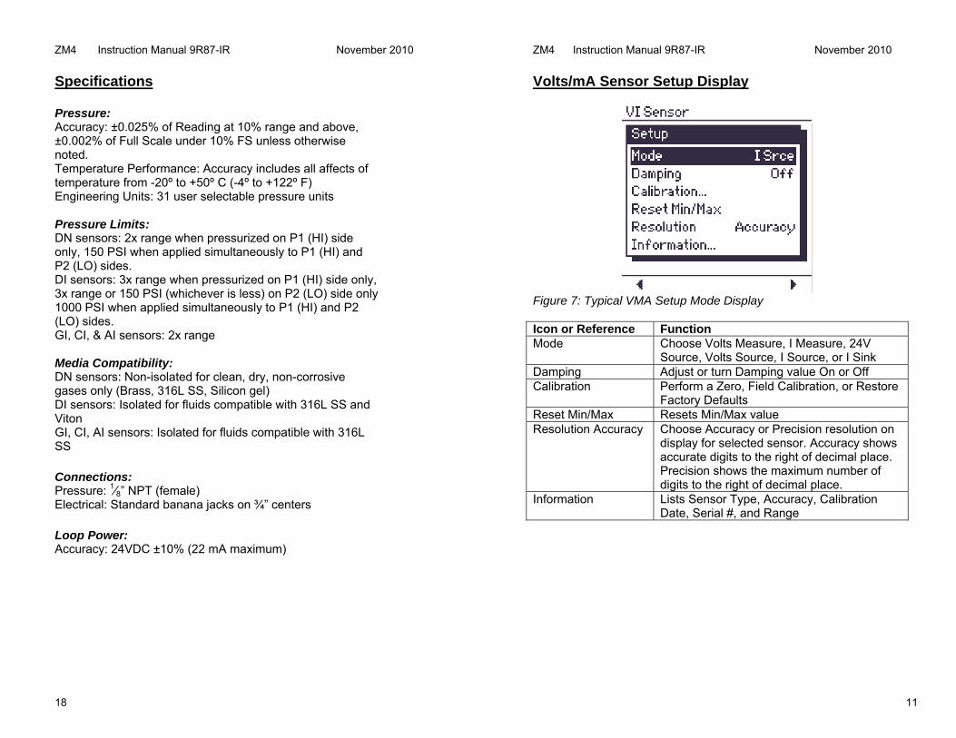
Volts/mA Sensor Setup Display
Figure 7: Typical VMA Setup Mode Display Icon or Reference Function Mode Choose Volts Measure, I Measure, 24V
Source, Volts Source, I Source, or I Sink Damping Adjust or turn Damping value On or Off Calibration Perform a Zero, Field Calibration, or Restore
Factory Defaults Reset Min/Max Resets Min/Max value Resolution Accuracy Choose Accuracy or Precision resolution on
display for selected sensor. Accuracy shows accurate digits to the right of decimal place. Precision shows the maximum number of digits to the right of decimal place.
Information Lists Sensor Type, Accuracy, Calibration Date, Serial #, and Range

ZM4 Instruction Manual 9R87-IR November 2010
12
Changing Batteries Loosen the two screws in the battery cover and lift off cover. Remove the batteries by gently applying pressure to the positive side and pull upward. To install batteries insert the negative side against the spring and gently apply pressure to lock in the positive side. The positive (+) and negative (-) battery polarity markings are located in the bottom of the case for the lower batteries and on the top of case for the upper batteries, as shown in the illustration. Once the batteries are secured in the battery compartment, replace battery cover and tighten the two flat head screws. The battery door is universal and can be installed in either direction. Figure 8: Changing Batteries
Warning – To avoid erratic readings replace batteries when warning message appears.
ZM4 Instruction Manual 9R87-IR November 2010
17
Specifications - Over and Under Range

ZM4 Instruction Manual 9R87-IR November 2010
16
Specifications – Range TYPE & RANGE
+/- 0.025% Reading unless otherwise noted below. Statement includes all affects of linearity, repeatability, hysteresis and temperature from -20º to +50º C (-4º to +104º F)
DN0010 0 TO 10 in H2O Differential, Non-isolated. (±0.05%) DN0028 0 TO 28 in H2O Differential, Non-isolated. DN0200 0 TO 200 in H2O Differential, Non-isolated DN0415 0 TO 415 in H2O Differential, Non-isolated DN2000 0 TO 2000 in H2O Differential, Non-isolated DI0001 0 TO 1 PSI Differential, Isolated DI0005 0 TO 5 PSI Differential, Isolated DI0015 0 TO 15 PSI Differential, Isolated DI0030 0 TO 30 PSI Differential, Isolated DI0100 0 TO 100 PSI Differential, Isolated DI0300 0 TO 300 PSI Differential, Isolated DI0500 0 TO 500 PSI Differential, Isolated GI0015 0 TO 15 PSI Gauge, Isolated GI0030 0 TO 30 PSI Gauge, Isolated GI0050 0 TO 50 PSI Gauge, Isolated GI0100 0 TO 100 PSI Gauge, Isolated GI0300 0 TO 300 PSI Gauge, Isolated GI0500 0 TO 500 PSI Gauge, Isolated GI1000 0 TO 1000 PSI Gauge, Isolated GI3000 0 TO 3000 PSI Gauge, Isolated CI0015 -15 TO +15 PSI Compound, Isolated CI0030 -15 TO +30 PSI Compound, Isolated CI0050 -15 TO +50 PSI Compound, Isolated CI0100 -15 TO +100 PSI Compound, Isolated CI0300 -15 TO +300 PSI Compound, Isolated CI0500 -15 TO +500 PSI Compound, Isolated AI0017 0 TO 17 PSIA Absolute, Isolated (0-900 mm Hg) AI0038 0 TO 38 PSIA Absolute, Isolated (0-2000 mm Hg) AI0100 0 TO 100 PSIA Absolute, Isolated (0-5200 mm Hg) AI1000 0 TO 1000 PSIA Absolute, Isolated (0-52000 mm Hg)
ZM4 Instruction Manual 9R87-IR November 2010
13
Accessing SD Card To install the SD™ card simply insert the card in the slot and press down until you hear a click. The card has only one orientation for correct alignment. Please make sure you are inserting a SANDISK P/N SDSDB-2048-A11 or equivalent. Further details on the card are provided under the specification section.
Please note there is a Lock located on the side of the SD™ card. When the Lock is pressed down information can only be read from the card. To write or save information to the card make sure it is Unlocked before installing.
Figure 9: Accessing SD Card

ZM4 Instruction Manual 9R87-IR November 2010
14
Downloading Data Using USB Interface The M4 has the capability to download the information stored on the SD card to a computer via the USB cable provided with the unit or via an SD card reader. The Meriam Setup Utility which allows you to download the data is provided on the CD or available at www.meriam.com. Please install the USB drivers before installing the program. The USB Interface is for the exchange of data only. Measurements taken while powered up by USB are for reference use only. The data file is downloaded as a .bin file and converted over to a .csv file for direct use in Microsoft Excel™. Select Device Native Output (USB) and press the Find Device button to find the M4.
Once the device is found press the Data Log Utility button and follow screen instructions.
ZM4 Instruction Manual 9R87-IR November 2010
15
Installing Wire Stand All M4 units come standard with an installed rear hand strap and a separate wire stand. To install the wire stand first pull down on the loose end of the Velcro strap to separate it, then carefully pull the strap through the lower bracket. Next remove the two Phillips screws that secure the top metal bracket. Locate the plastic bag that contains the wire stand, rubber mounting bracket, and two Phillips screws. Align the plastic mounting holes with the two brass inserts. Please make sure the straight edge is facing upward toward the pressure manifold as shown in the illustration. Secure the plastic mounting block to the enclosure by tightening the screws. Figure 10: Installing Wire Stand