Embed Size (px)
Citation preview
M_M
40 s
erie
s_EN
_A -
Last
upd
ated
: 05/
2017
- Tr
ansl
atio
n of
the
Fren
ch o
rigin
al d
ocum
ent
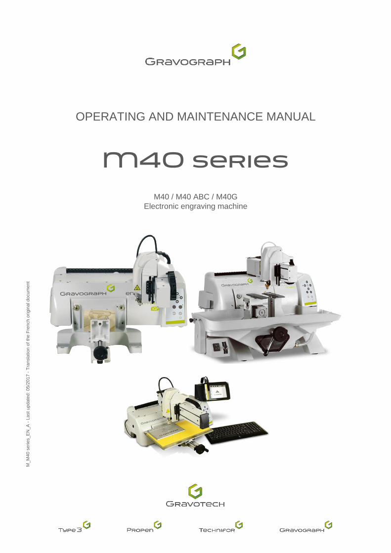
OPERATING AND MAINTENANCE MANUAL
M40 seriesM40 / M40 ABC / M40G
Electronic engraving machine

Table of contents
M_M40 series_EN_A 2
A. Foreword ...................................................................................................................................................5
1. Appreciation ...........................................................................................................................................52. Information .............................................................................................................................................5
B. Legal notices ............................................................................................................................................6
C. Regulation observance ............................................................................................................................7
D. Introduction ..............................................................................................................................................8
1. Presentation ...........................................................................................................................................82. Identificationofthemarkingequipment..................................................................................................83. Workstationsafety .................................................................................................................................9
� Handling the machine ..........................................................................................................................9
� M40 ABC : precautions for use of the touch-screen ............................................................................9
E. Unpacking ...............................................................................................................................................10
1. Unpacking ............................................................................................................................................102. Packagecontents .................................................................................................................................11
� For all machines ................................................................................................................................11
� M40 .....................................................................................................................................................12
� M40 ABC ............................................................................................................................................12
� M40G ..................................................................................................................................................12
3. Toolbox: content ...................................................................................................................................13 � For all machines ................................................................................................................................13
� M40 .....................................................................................................................................................13
� M40 ABC ............................................................................................................................................13
� M40G ..................................................................................................................................................14
F. Safety .......................................................................................................................................................15
1. Recommendationsandsafety ..............................................................................................................15 � Personnelsafety ................................................................................................................................15
� Wearingsafetyglasses ......................................................................................................................15
� Requiredsafetylabels .......................................................................................................................16
G. Description of the machine ...................................................................................................................17
1. M40 / M40 ABC: front view of the machine ..........................................................................................17 � Engraving table ..................................................................................................................................17
� Tool holder .........................................................................................................................................18
� M40 ABC: Touch Pad .........................................................................................................................18

M_M40 series_EN_A 3
2. M40G: front view of the machine ..........................................................................................................19 � Engraving table ..................................................................................................................................19
� Tool holder .........................................................................................................................................20
3. Rear view of the machine .....................................................................................................................21 � Left side view of the machine ............................................................................................................21
� M40 ABC: Touch Pad (rear view) .......................................................................................................22
4. Control panel ........................................................................................................................................23 � Indicator light function ........................................................................................................................24
H. Recommendations for installation .......................................................................................................25
1. Physicalinstallation ..............................................................................................................................252. Electrical installation .............................................................................................................................26
I. Connections - Installation .....................................................................................................................27
1. Connections .........................................................................................................................................27 � Powersupplyconnection ...................................................................................................................27
� Using the PLC function (user standard inputs/outputs) ......................................................................28
2. Machine / PC connection .....................................................................................................................29 � Machine / PC connection (USB connection) .......................................................................................29
3. M40 ABC: installation and wiring of the Touch Pad .............................................................................30 � Installation on the machine ................................................................................................................30
� Connections and cabling ...................................................................................................................32
4. Installation ............................................................................................................................................33 � Switching on the machine ..................................................................................................................33
� Resolution of the problems ................................................................................................................33
� Power down .......................................................................................................................................33
� Restarting ..........................................................................................................................................34
� Program installation ...........................................................................................................................34
J. Using the machine .................................................................................................................................35
1. Transfer of the composition to the machine .........................................................................................352. Positioning the object to be engraved ..................................................................................................35
� M40 / M40 ABC: positioning a plate in the vice .................................................................................35
� M40 / M40 ABC: positioning a plate on the table ...............................................................................37
� M40G:positioningacylinderonthecylinderattachment ..................................................................37
3. Adjustment on the tool holder ...............................................................................................................39 � Spindle pressure adjustment .............................................................................................................39
� Engraving with a regulating nose .......................................................................................................40
4. Mounting the cutter on the tool holder ..................................................................................................415. Setting the origin of the tool carrier ......................................................................................................42
� M40 / M40G ........................................................................................................................................42
� M40 ABC ............................................................................................................................................42
6. Adjusting the engraving depth ..............................................................................................................437. Start-up engraving ................................................................................................................................44

M_M40 series_EN_A 4
K. Preventive maintenance ........................................................................................................................45
1. General maintenance ...........................................................................................................................45 � M40 ABC: color touch screen (Touch Pad) ........................................................................................45
2. Changing the fuse ................................................................................................................................463. M40G:everyweek ...............................................................................................................................474. M40G:everymonth ..............................................................................................................................47
� Lubricanttankdrainingandcleaning .................................................................................................47
� Lubricant pump cleaning ....................................................................................................................49
5. Adjusting the machine ..........................................................................................................................50 � Setting the table zero point (function not available for the M40G machine) .......................................50
� Setting the vice zero point .................................................................................................................51
� Adjusting the machine in Z ................................................................................................................52
� M40 ABC ...........................................................................................................................................52
L. Technicalspecifications ........................................................................................................................53
1. Physicalcharacteristics ........................................................................................................................532. Engraving characteristics .....................................................................................................................533. Noise emission of the machine (ISO 11201 standard) ..........................................................................544. Electrical characteristics .......................................................................................................................545. Environment .........................................................................................................................................546. Point and shoot .....................................................................................................................................547. Connection(s) .......................................................................................................................................55
� M40 / M40G ........................................................................................................................................55
� M40 ABC ...........................................................................................................................................55
8. TouchPadkit(M40ABC)......................................................................................................................559. Cylinderattachment(M40G) .................................................................................................................56
� Motorized vice ....................................................................................................................................56
� Lubricantsystem ................................................................................................................................56

M_M40 series_EN_A 5
A. Foreword
1. Appreciation
ThankyouforchoosingM40series-Gravograph.
Gravotechispleasedtocountyouamongtheusersofitsengravingandtraceabilitysolutions.
For help, contact Gravotech.
For more information on products, visit www.gravograph.com website.
2. Information
To ensure security and productivity, read this manual before starting-up the equipment. It provides details about the installation and use of the equipment.
Keep this manual in case you need to refer to it.
Fortheattentionofusershavinganindividualcardiacassistdevicefitted:
Our equipment is designed and manufactured with the greatest care in order to guarantee their compliance with the EMC Directive currently in force. This means that the levels of electromagnetic emissions produced by this equipment when in operationarelimitedanddonotexceedthethresholdsdefinedbytheDirective.
However, multiple factors make it impossible to guarantee the total absence of risk forusershavingacardiacassistdevicefitted.Consequently,itisrecommendedthatstanding for a prolonged period within less than 1 m (3.281 ft) of an operating machine should be avoided.

M_M40 series_EN_A 6
B. Legal notices Last updated: 10/15
Thepurposeofthisdocumentistoprovideusers(hereinaftertheUser(s))withinformationandtoensuretheirsafety.Ithasnocontractualvalue and Gravotech group (hereinafter Gravotech) reserves the right, at any time and without notice, to make such changes orimprovementsasitdeemsfits,ortosubstituteanynewequipmentand/ormaterialand/orpartand/orimagetoitsequipment,softwareand/or associated manuals or documentation (hereinafter the Product(s)).
Thismanual,includingtexts,images,photos,graphics,design,oranycompilation,digitalconversionordatacontainedinit,issubjecttocopyright.Thismanualshallnotbereproduced,disseminated,transmitted,transcribed,translatedorstoredelectronically,onanymediumwhatsoeverregardlessofitsformatwithouttheexpressandwrittenpermissionofGravotech,totheexceptionofsoftwarebackupcopiesasprovidedbylaw.
TheintellectualpropertyrightsrelatingtotheProductsandtothismanual,including-butnotlimitedto-patents,trademarks,models,copyright, domain namesandalso the know-how, trading nameor companyname, are ownedbyGravotechMarkingS.A.Sor anycompanyoftheGravotechgroup.UndernocircumstancesdoesthetransmissionofthismanualorthesupplyofProductsorservicesconstituteanassignmentoforanyexpressortacitlicenseforanyintellectualpropertyrightownedbyGravotech.
Totheextentpermittedbylaw,Gravotechprovidesherebynowarranty(inparticularnowarrantiesofperformance,non-infringement,merchantabilityorfitnessforaparticularpurpose)relatingtothesupplyof itsProducts,other thanthoseconferredupontheUserbyGravotech's general terms and conditions of sale or any contractual document agreed betweenGravotech and theUser.Nor doesGravotechguaranteethecompatibilityofitssoftwarewithanysoftwarepackagenotsuppliedbyit,oranydefectinassembly,adaptation,design,compatibilityandoperationwithanyorpartofacombinationcreatedbytheUser.
Gravotech shall not be liable for any damages, that theUser or its property, a third party or the Product itselfmay suffer, causedbytheProductandarisingfromanyinappropriateuseormisuseoftheProduct,negligence,carelessness, inadequatesupervisionormaintenance,failuretoobservethesafetyorusageinstructionsdescribedhereinorotherwisecommunicatedtotheUser,theuseofpoor-qualityornon-recommendedlubricants,fluidsandadditivesorwherethereisfaultonthepartoftheUserorathirdparty.Asprovidedinthis manual, the User shall furthermore (i) observe the normal conditions of use, (ii) not exceed the recommended maximum number of hoursduringwhichtheequipmentmaybeoperatedonand(iii)refrainfromproceedingtoanyProduct'srepairormakeitproceedbyanyunqualifiedthirdparty,orwithouttheappropriatepersonalprotectiveequipment.
TheProduct'sspecificationsarealteredby(i)anyProduct'smodificationoralteration,(ii)anyadaptationandinstallationofaccessoriesthatarenot recommendedbyGravotech, (iii) the integrationofacontrolsystemand (iv) theconnection toanexternaldevice.Suchspecifications' alterationsmay lead to the non-compliance of theProductwith applicable rules and standards. Shall theProduct benon-compliant,thepersoninchargeoftheProduct'sinstallationshallberesponsibleofthefinalworkstation'scompliance.Innoevent,Gravotechshallbeliableforanydamagesarisingfromsuchnon-recommendedorunauthorizedProduct'salterations.Itisprecisedthatthewarrantyshallnotapplyinsuchcase.
UndernocircumstancesshallGravotechbeheldliableforanyindirect,incidental,special,consequentialpunitiveorothersimilardamages,includinganyeconomicloss, lossofprofit, lossofdataoropportunity,whetherornotforeseeablebyorcommunicatedtoGravotech,causedbythismanualorthesupplyofProductsorservicesconcernedbythesaidmanual.
Tothewidestextentpermittedbylaw,Gravotechshallonlybeheldliablefordirectdamagearisingfrompersonalinjurycausedbyafaultproven in its Product (including this manual).
Gravotech®-Type3®-Propen™-Technifor™-Gravograph®is(are)aused,pendingorregisteredtrademark(s)ofGravotechgrouporone of its subsidiaries.
Theproductsandnamesofthirdpartycompanieswhichappearinthismanualareusedsolelyforthenecessarypurposesofreference,andinparticularforissuesofcompatibility.Allthetrademarksmentionedinthismanualremainthepropertyoftheirrespectiveowners.Windows®is(are)aused,pendingorregisteredtrademark(s)ofMicrosoftCorporation.Postscript®is(are)aused,pendingorregisteredtrademark(s)ofAdobeSystemsIncorporated.
M_M40 series_EN_A 7
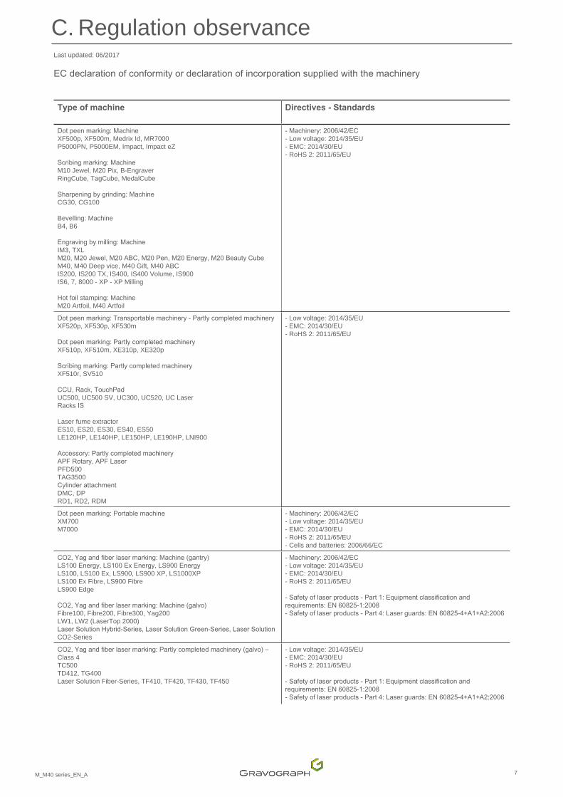
Last updated: 06/2017
ECdeclarationofconformityordeclarationofincorporationsuppliedwiththemachinery
Type of machine Directives - Standards
Dotpeenmarking:Machine XF500p, XF500m, Medrix Id, MR7000 P5000PN, P5000EM, Impact, Impact eZ Scribingmarking:Machine M10 Jewel, M20 Pix, B-Engraver RingCube, TagCube, MedalCube
Sharpeningbygrinding:Machine CG30, CG100 Bevelling: Machine B4, B6
Engravingbymilling:MachineIM3, TXL M20,M20Jewel,M20ABC,M20Pen,M20Energy,M20BeautyCubeM40, M40 Deep vice, M40 Gift, M40 ABC IS200, IS200 TX, IS400, IS400 Volume, IS900 IS6, 7, 8000 - XP - XP Milling
Hot foil stamping: Machine M20 Artfoil, M40 Artfoil
-Machinery:2006/42/EC- Low voltage: 2014/35/EU - EMC: 2014/30/EU - RoHS 2: 2011/65/EU
Dotpeenmarking:Transportablemachinery-Partlycompletedmachinery XF520p, XF530p, XF530m
Dotpeenmarking:Partlycompletedmachinery XF510p, XF510m, XE310p, XE320p
Scribingmarking:Partlycompletedmachinery XF510r, SV510
CCU,Rack,TouchPad UC500, UC500 SV, UC300, UC520, UC Laser RacksIS
Laser fume extractor ES10, ES20, ES30, ES40, ES50 LE120HP, LE140HP, LE150HP, LE190HP, LNI900
Accessory:Partlycompletedmachinery APFRotary,APFLaserPFD500 TAG3500Cylinderattachment DMC, DPRD1, RD2, RDM
- Low voltage: 2014/35/EU - EMC: 2014/30/EU - RoHS 2: 2011/65/EU
Dotpeenmarking:Portablemachine XM700 M7000
-Machinery:2006/42/EC- Low voltage: 2014/35/EU - EMC: 2014/30/EU - RoHS 2: 2011/65/EU - Cells and batteries: 2006/66/EC
CO2,Yagandfiberlasermarking:Machine(gantry) LS100Energy,LS100ExEnergy,LS900Energy LS100, LS100 Ex, LS900, LS900 XP, LS1000XP LS100 Ex Fibre, LS900 FibreLS900 Edge
CO2,Yagandfiberlasermarking:Machine(galvo) Fibre100, Fibre200, Fibre300, Yag200 LW1, LW2 (LaserTop 2000)LaserSolutionHybrid-Series,LaserSolutionGreen-Series,LaserSolutionCO2-Series
-Machinery:2006/42/EC- Low voltage: 2014/35/EU - EMC: 2014/30/EU - RoHS 2: 2011/65/EU
-Safetyoflaserproducts-Part1:Equipmentclassificationandrequirements:EN60825-1:2008-Safetyoflaserproducts-Part4:Laserguards:EN60825-4+A1+A2:2006
CO2,Yagandfiberlasermarking:Partlycompletedmachinery(galvo)–Class 4 TC500 TD412, TG400 Laser Solution Fiber-Series, TF410, TF420, TF430, TF450
- Low voltage: 2014/35/EU - EMC: 2014/30/EU - RoHS 2: 2011/65/EU
-Safetyoflaserproducts-Part1:Equipmentclassificationandrequirements:EN60825-1:2008-Safetyoflaserproducts-Part4:Laserguards:EN60825-4+A1+A2:2006
C. Regulation observance
8M_M40 series_EN_A
D. Introduction
1. Presentation
The M40 series machines are electronic engraving machines.
• Theyareprovidedwithakeypadforcontrollingthemachine.
• Thefilestobeengravedaretransferredfromthesoftwaretotheengravingmachine.
• Engravingisperformedbythetoolholderassembly.
M40ABC:Itisnecessarytohaveanexternalstandardkeyboard(notsupplied).
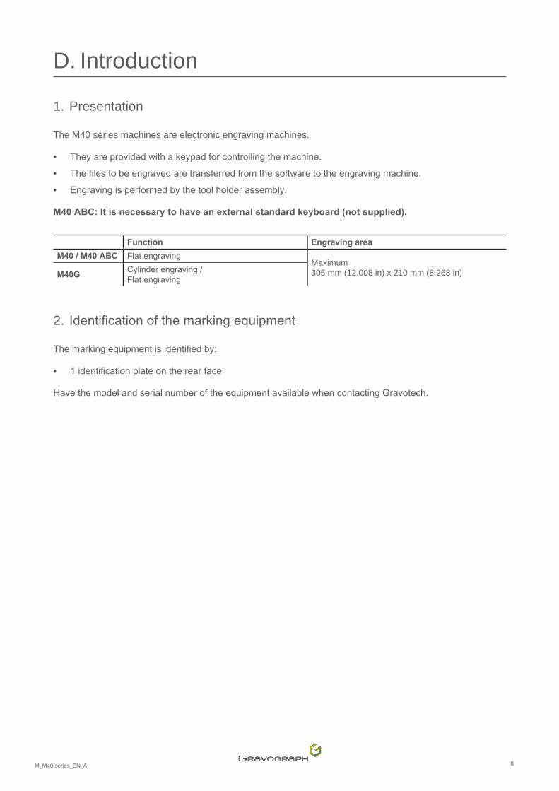
Function Engraving area
M40 / M40 ABC Flat engraving Maximum 305 mm (12.008 in) x 210 mm (8.268 in)M40G
Cylinderengraving/Flat engraving
2. Identificationofthemarkingequipment
Themarkingequipmentisidentifiedby:
• 1identificationplateontherearface
HavethemodelandserialnumberoftheequipmentavailablewhencontactingGravotech.

9M_M40 series_EN_A
Introduction 3. Workstationsafety• Turnoffthemachinebeforebeginninganycleaning,maintenanceorrepairprocedure.
� Handling the machine
• Any operations on the machine must be carried out under the responsibility of an adult. Do not allow children to touch the machine, leads or cables.
• Nevermovethetoolholdermanually,exceptintheeventofamechanicalblockageofthemachine.
• In the event of an extended period of non-use, unplug the power cable and protect the machine.
• Neverpourorspillliquidonthemachine(drinks,cleaningproducts,etc.)exceptwhererecommendedbyGravotech.
• Donotplaceanyobjectonthemachineotherthantheobjecttobeengraved.
• UsethemachinewithGravographtoolsonly.
• Thismachineisdesignedforasingleuseronly.Donotallowitsoperationbymultipleusersatthesametime.
� M40 ABC : precautions for use of the touch-screen
• Donottouchthesurfaceofthescreenwithhardmaterials(metal,glassorfingernails).
• Keep the touch-screen out of direct sunlight.
• Avoidextendedexposuretoahightemperaturesand/oranexcessivelydampenvironment.
• Theliquidinthetouch-screenisahazardoussubstance.Intheeventofcontactwiththissubstance,washimmediatelywithsoapandwater.
10M_M40 series_EN_A
E. Unpacking
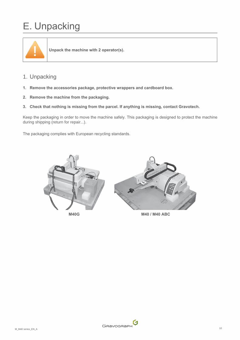
Unpack the machine with 2 operator(s).
1. Unpacking
1. Remove the accessories package, protective wrappers and cardboard box.
2. Remove the machine from the packaging.
3. Check that nothing is missing from the parcel. If anything is missing, contact Gravotech.
Keepthepackaginginordertomovethemachinesafely.Thispackagingisdesignedtoprotectthemachineduring shipping (return for repair...).
ThepackagingcomplieswithEuropeanrecyclingstandards.
M40G M40 / M40 ABC
11M_M40 series_EN_A
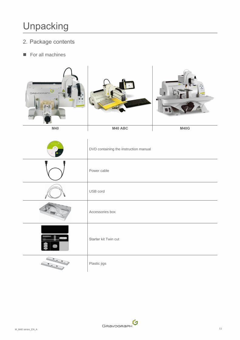
Unpacking2. Packagecontents
� For all machines
M40 M40 ABC M40G
DVD containing the instruction manual
Power cable
USB cord
Accessories box
Starterkit Twin cut
Plastic jigs
12M_M40 series_EN_A
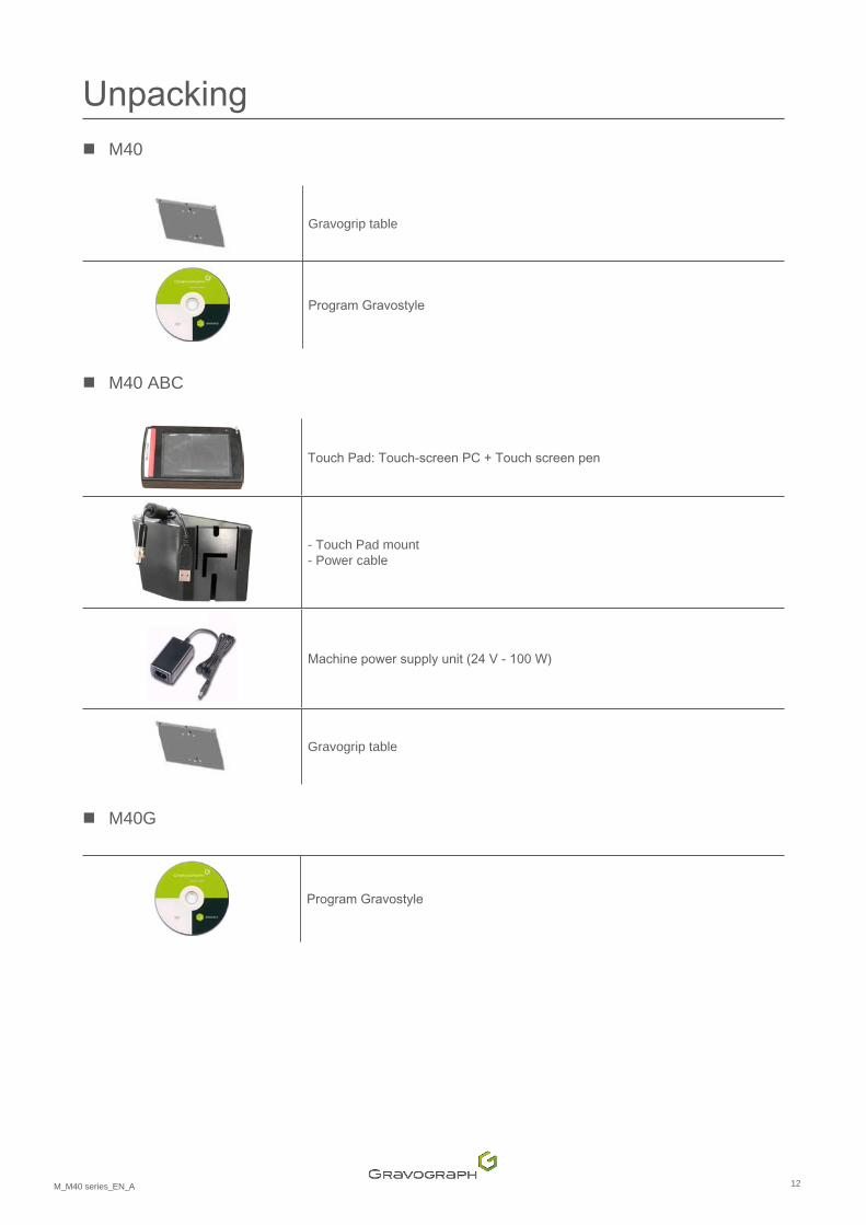
Unpacking � M40
Gravogrip table
ProgramGravostyle
� M40 ABC
TouchPad:Touch-screenPC+Touchscreenpen
- Touch Pad mount - Power cable
Machinepowersupplyunit(24V-100W)
Gravogrip table
� M40G
ProgramGravostyle
13M_M40 series_EN_A
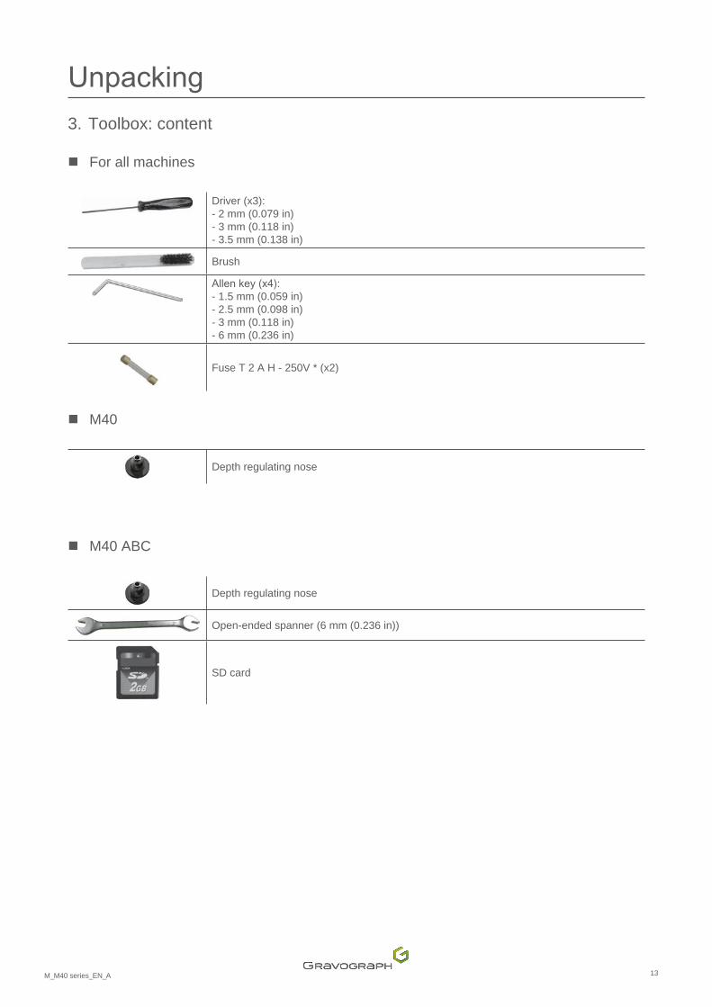
Unpacking3. Toolbox: content
� For all machines
Driver (x3):- 2 mm (0.079 in)- 3 mm (0.118 in)- 3.5 mm (0.138 in)
Brush
Allenkey(x4):- 1.5 mm (0.059 in)- 2.5 mm (0.098 in)- 3 mm (0.118 in)- 6 mm (0.236 in)
Fuse T 2 A H - 250V * (x2)
� M40
Depth regulating nose
� M40 ABC
Depth regulating nose
Open-ended spanner (6 mm (0.236 in))
SD card
14M_M40 series_EN_A
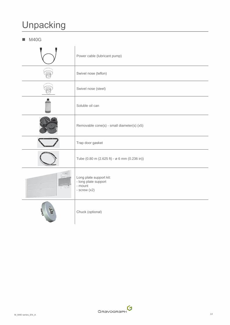
Unpacking � M40G
Power cable (lubricant pump)
Swivelnose(teflon)
Swivel nose (steel)
Soluble oil can
Removable cone(s) - small diameter(s) (x5)
Trapdoorgasket
Tube (0.80 m (2.625 ft) - ø 6 mm (0.236 in))
Longplatesupportkit:- long plate support - mount - screw (x2)
Chuck(optional)

15M_M40 series_EN_A
F. Safety
1. Recommendationsandsafety
� Personnelsafety
The machine is designed for light engraving only and under no circumstances should it be used for other applications.
Do not use this marking equipment in an explosive environment.
Do not use this machine for routing or intensive cutting operations. Do not use this machine for wood work.
Never hold the materials for engraving by the hands. Use only Gravograph clamping systems designed for the machine.
During engraving operations, use this machine with a (regulating or suction) nose in order to prevent flyingswarf.
Donotstartengravingwithoutfirstensuringthattheobjecttobeengravedissecurelyclamped.
Never take hold of the material for engraving when engraving is in progress.
Interrupt engraving by means of the function provided for this purpose on the machine control panel.
Keep away from the area above the machine.
Ensure that people are kept clear of the area of travel of the moving parts of the machine and that no objectsriskobstructingtheirmovement.
During engraving, the rotation of the spindle could present risks of burns and cuts.
To avoid any risks of getting burnt, the protective housing of the tool-holder must be always closed, exceptwhencarryingoutadjustments.
Topreventanyriskofcrushing,avoidplacingthehandsinthelocationsidentified.
Keep clear of the tool-holder.
� Wearingsafetyglasses
Theuseofsafetyglassesisrecommendedforprotectionagainstflyingswarf.

16M_M40 series_EN_A
Safety � Requiredsafetylabels
CAUTION - LASER RADIATION
Do not stare into beam.
Laserdiode-Wavelength:630-680nm-Output(maximum)<1mW
CLASS 2 LASER PRODUCT
Warning: Hot surface
Warning: Crushing risk
Warning: Laser beam General warning Rotation of the spindle: Riskofburnsandcuts
17M_M40 series_EN_A
G. Description of the machine
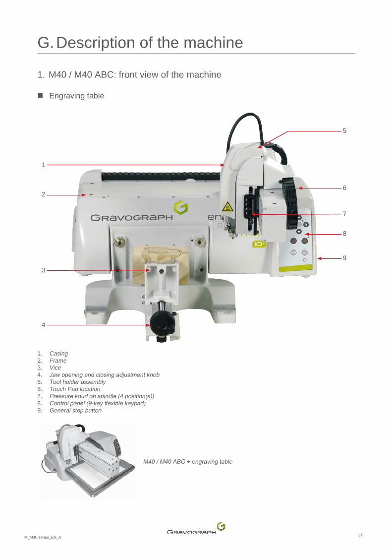
1. M40 / M40 ABC: front view of the machine
� Engraving table
2
3
4
5
6
8
9
7
1
1. Casing 2. Frame 3. Vice 4. Jawopeningandclosingadjustmentknob5. Toolholderassembly6. Touch Pad location 7. Pressureknurlonspindle(4position(s))8. Controlpanel(9-keyflexiblekeypad)9. General stop button
M40/M40ABC+engravingtable
18M_M40 series_EN_A
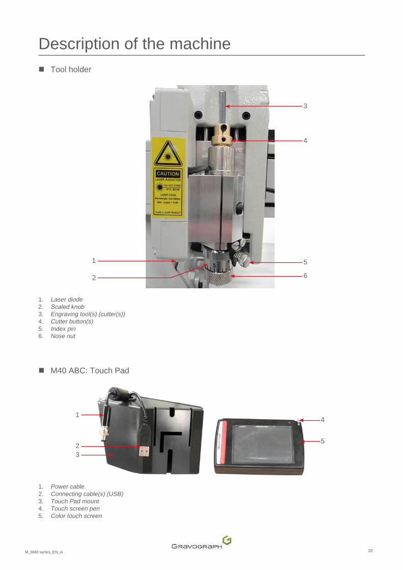
Description of the machine � Tool holder
6
1
2
3
4
5
1. Laser diode 2. Scaledknob3. Engraving tool(s) (cutter(s))4. Cutter button(s) 5. Index pin 6. Nose nut
� M40 ABC: Touch Pad
5
1
23
4
1. Power cable 2. Connecting cable(s) (USB)3. Touch Pad mount 4. Touch screen pen 5. Color touch screen
19M_M40 series_EN_A
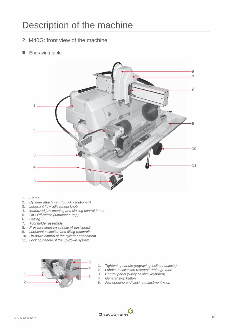
Description of the machine 2. M40G: front view of the machine
� Engraving table
1
2
3
4
5
9
10
11
67
8
1. Frame 2. Cylinderattachment(chuck-(optional))3. Lubricantflowadjustmentknob4. Motorized jaw opening and closing control button 5. On/Offswitch(lubricantpump)6. Casing 7. Toolholderassembly8. Pressureknurlonspindle(4position(s))9. Lubricantcollectionandfillingreservoir10. Up-downcontrolofthecylinderattachment11. Lockinghandleoftheup-downsystem
2
1
34
5
1. Tightening handle (engraving inclined objects)2. Lubricant collection reservoir drainage tube 3. Controlpanel(9-keyflexiblekeyboard)4. General stop button 5. Jawopeningandclosingadjustmentknob
20M_M40 series_EN_A
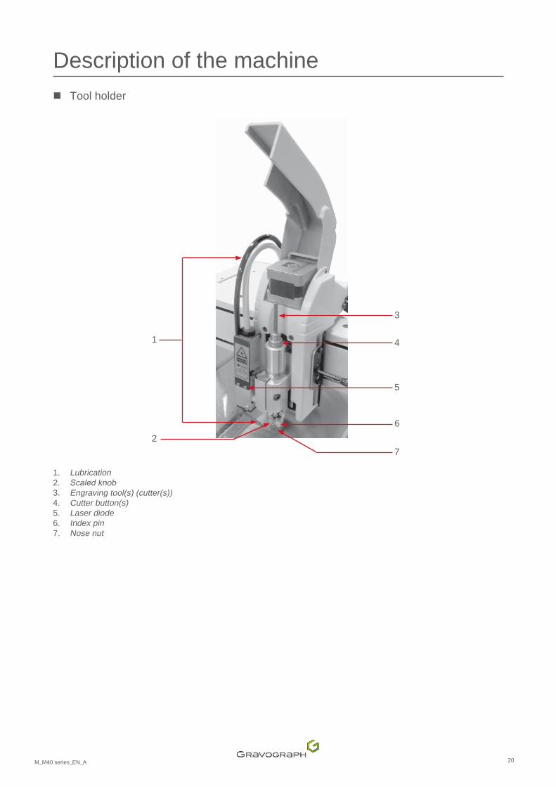
Description of the machine � Tool holder
1
3
4
5
62
7
1. Lubrication 2. Scaledknob3. Engraving tool(s) (cutter(s))4. Cutter button(s) 5. Laser diode 6. Index pin 7. Nose nut
21M_M40 series_EN_A
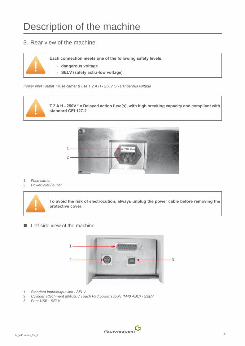
Description of the machine 3. Rear view of the machine
Eachconnectionmeetsoneofthefollowingsafetylevels:
- dangerous voltage
- SELV (safety extra-low voltage)
Powerinlet/outlet+fusecarrier(FuseT2AH-250V*)-Dangerousvoltage
T 2 A H - 250V * = Delayed action fuse(s), with high breaking capacity and compliant with standard CEI 127-2
1
2
1. Fuse carrier 2. Power inlet / outlet
To avoid the risk of electrocution, always unplug the power cable before removing the protective cover.
� Left side view of the machine
1
2 3
1. Standardinput/outputlink-SELV2. Cylinderattachment(M40G)/TouchPadpowersupply(M40ABC)-SELV3. Port: USB - SELV
22M_M40 series_EN_A
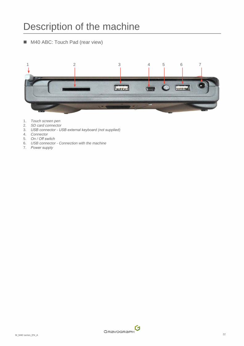
Description of the machine � M40 ABC: Touch Pad (rear view)
1 2 3 4 5 6 7
1. Touch screen pen 2. SD card connector 3. USBconnector-USBexternalkeyboard(notsupplied)4. Connector 5. On/Offswitch6. USB connector - Connection with the machine 7. Powersupply
23M_M40 series_EN_A
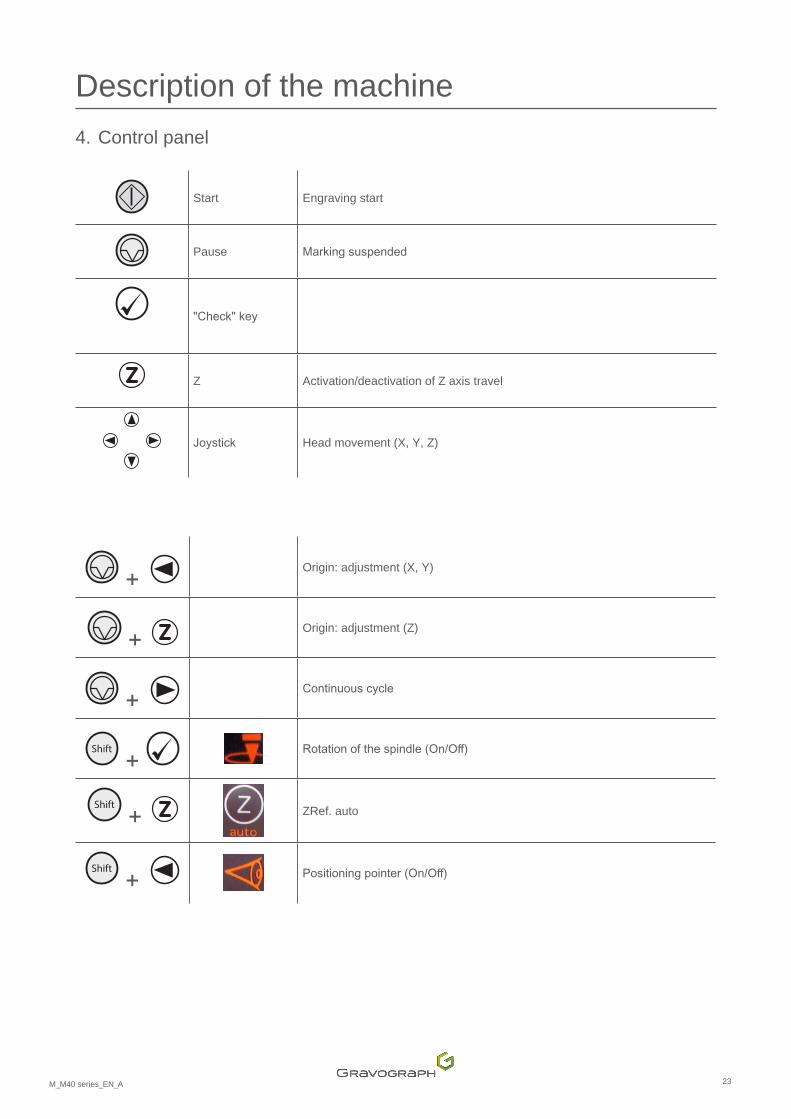
Description of the machine 4. Control panel
Start Engraving start
Pause Markingsuspended
"Check"key
Z Activation/deactivation of Z axis travel
Joystick Head movement (X, Y, Z)
+ Origin: adjustment (X, Y)
+ Origin: adjustment (Z)
+ Continuouscycle
Shift
+ Rotationofthespindle(On/Off)
Shift
+ ZRef. auto
Shift
+ Positioningpointer(On/Off)
24M_M40 series_EN_A
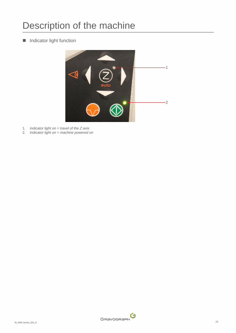
Description of the machine � Indicator light function
1
2
1. Indicator light on = travel of the Z axis 2. Indicator light on = machine powered on

25M_M40 series_EN_A
H. Recommendations for installation
Turnoff themachinebefore any intervention (put theOn/Offswitch in the "O" (Off)position).
1. Physicalinstallation• Placethemachineonahorizontal,stableandcleansurfacethatcansupport100kg(220.462lb)ormore.
• Place the machine in a clean, ventilated environment.
• Avoidsmall,confined,unventilatedspaces.
• Ambientlightisenoughtolighttheequipmentproperly.
• Arrangetheworksurfaceforrapidandeasyaccesstoeachexternalpartofthemachineand,ifnecessary,to the main machine stop button.
• Do not obstruct the movement of the moving parts of the machine.
Make sure the connector screws are properly tightened to prevent the cables from becoming disconnected while the machine is switched on. This could cause permanent damage to the circuit boards.
Thepowercablemustalwaysbeeasilyaccessible(powershut-offdevice).
• Protecttheequipmentagainst: - damp (rain, snow, condensation etc.)
- heat (exposure to full sun, heating etc.)
- sudden changes in temperature
- dust (extraction duct)
- spillagesofliquidsontotheelectricalunit,cablesandconnections,andallotherpartsofthemachine(exceptinsituationsrecommendedbyGravotech(lubrication))
- vibrations
- electrical/electronic radiation

26M_M40 series_EN_A
Recommendations for installation 2. Electrical installation
The connection to the single phase power supply is made with a standard, 3 pin plug withgrounding.Groundingmustbedoneaccordingtotheregulationsineffecttoensurethe safety of the personnel.
Checkthattheelectrical installationmeetstherequirementsof the"Inputpower" label locatedclosetothemachine'spowersupplysocket.
To avoid interference problems due to the external environment, observe the following:
• Usethelinkcablessupplied.TheycomplywithEMCradio-frequencyinterferenceemissionstandardsandprovideprotectionfromexternalelectrical interference(compliantwithEMCimmunityandsusceptibilitystandards).
• Bringtheitemsofequipmenttobelinkedasclosetogetheraspossibletoreducethelengthofcabletobeused.
• Separatethepowercablefromthelinkcableandmakesurethepowerandlinkcablesdonotrunthroughthesamecabletray.
• Connect the machine direct to a mains power line and avoid connecting more than one device to that line (bypluggingseveraldevicesintothesamemainssocketorintoamulti-wayadapter).Exception:Whereequipmentisconnected,suchasacomputerandthemachine,supplypowertothedevicesthroughthesame mains power line.
• Do not allow inductive or capacitive devices to be connected to the same mains power line as the machine (motors, solenoid valves, chargers, etc.).
• Avoid the installationofmanualorautomaticswitchingsystemson thesamemainspower lineas themachine(relays,timers,programmers,automaticcircuit-breakers,automaticswitches,etc.).
• Check thatdevices in thevicinityof themachinemeet thestandards forelectromagnetic interference.Readthetechnicaldatasheetforeachdevice.Iftheyarenon-compliant,movethemasfarawayfromthemachine as possible.
• Use the Gravograph accessories.
Alwaysswitchthemachineoffbeforeconnectingordisconnectingacableoroptionalaccessory.
27M_M40 series_EN_A
I. Connections - Installation
1. Connections
� Powersupplyconnection
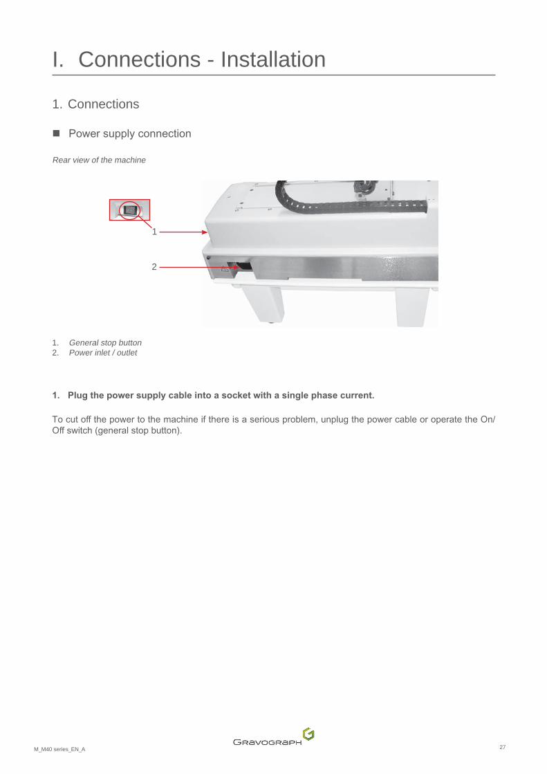
Rear view of the machine
2
1
1. General stop button 2. Power inlet / outlet
1. Plug the power supply cable into a socket with a single phase current.
Tocutoffthepowertothemachineifthereisaseriousproblem,unplugthepowercableoroperatetheOn/Offswitch(generalstopbutton).

28M_M40 series_EN_A
Connections - Installation � Using the PLC function (user standard inputs/outputs)
Function not available for the M40 ABC machine
Beforemakingany"userstandardinput/output"connections,checkthattheelectricalandelectroniccharacteristicsofthedifferentinputsandoutputsarerespected.Incorrectconnection could permanently damage the machine electronics.
Using the PLC function means that it is not just a matter of considering themachine on its own in order to ensure operator safety. The machine becomes part of a larger process (automated line). When completely assembled, the entire work station must meet the regulatory safety requirements. In this case, the machine and equipment installer is responsible for the final workstation's compliance.
The "Inputs/Outputs" function activation menu is accessed via the engraving software installed on the PC.
• 4inputscanbedefined(I1-I4):5INvaluesavailable.
• 4outputscanbedefined(O1-O4):5OUTvaluesavailable.
Input / Output characteristics Voltage and current Active state Minimum signal duration (active
state)
Input TTL-compatible Low 200 msOutput Open commutator - -
Wiring of the female 15 SubD connector Number Name Function Description
1 O1 Output Output 1 2 O2 Output Output 2 3 O3 Output Output 3 4 O4 Output Output 4 5 5 V 5Vpowersupply6 I1 Input Floating contact 1 7 I3 Input Floating contact 3 8 0 V Grounding 9 - Not available 10 - Not available 11 0 V Grounding 12 0 V Grounding 13 0 V Grounding 14 I2 Input Floating contact 2 15 I4 Input Floating contact 4
29M_M40 series_EN_A
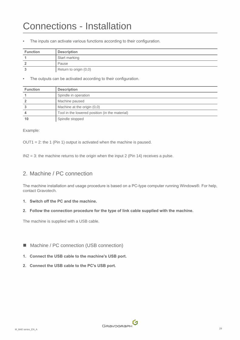
Connections - Installation • Theinputscanactivatevariousfunctionsaccordingtotheirconfiguration.
Function Description
1 Startmarking2 Pause 3 Return to origin (0,0)
• Theoutputscanbeactivatedaccordingtotheirconfiguration.
Function Description
1 Spindle in operation 2 Machine paused 3 Machine at the origin (0,0)4 Tool in the lowered position (in the material)10 Spindle stopped
Example:
OUT1 = 2: the 1 (Pin 1) output is activated when the machine is paused.
IN2 = 3: the machine returns to the origin when the input 2 (Pin 14) receives a pulse.
2. Machine / PC connection
ThemachineinstallationandusageprocedureisbasedonaPC-typecomputerrunningWindows®.Forhelp,contact Gravotech.
1. SwitchoffthePCandthemachine.
2. Follow the connection procedure for the type of link cable supplied with the machine.
The machine is supplied with a USB cable.
� Machine / PC connection (USB connection)
1. Connect the USB cable to the machine's USB port.
2. Connect the USB cable to the PC's USB port.
30M_M40 series_EN_A
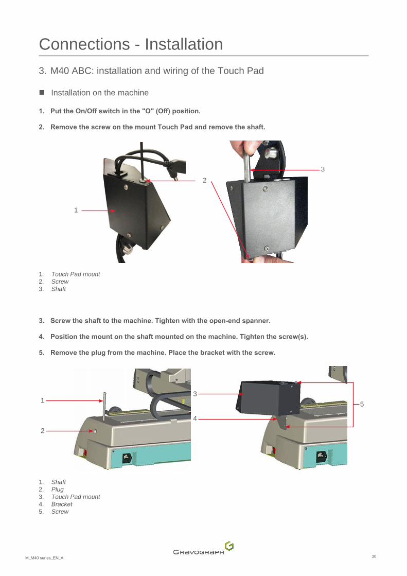
Connections - Installation 3. M40 ABC: installation and wiring of the Touch Pad
� Installation on the machine
1. PuttheOn/Offswitchinthe"O"(Off)position.
2. Remove the screw on the mount Touch Pad and remove the shaft.
2
1
3
1. Touch Pad mount 2. Screw 3. Shaft
3. Screw the shaft to the machine. Tighten with the open-end spanner.
4. Position the mount on the shaft mounted on the machine. Tighten the screw(s).
5. Remove the plug from the machine. Place the bracket with the screw.
1
2
3
4
5
1. Shaft 2. Plug 3. Touch Pad mount 4. Bracket5. Screw
31M_M40 series_EN_A
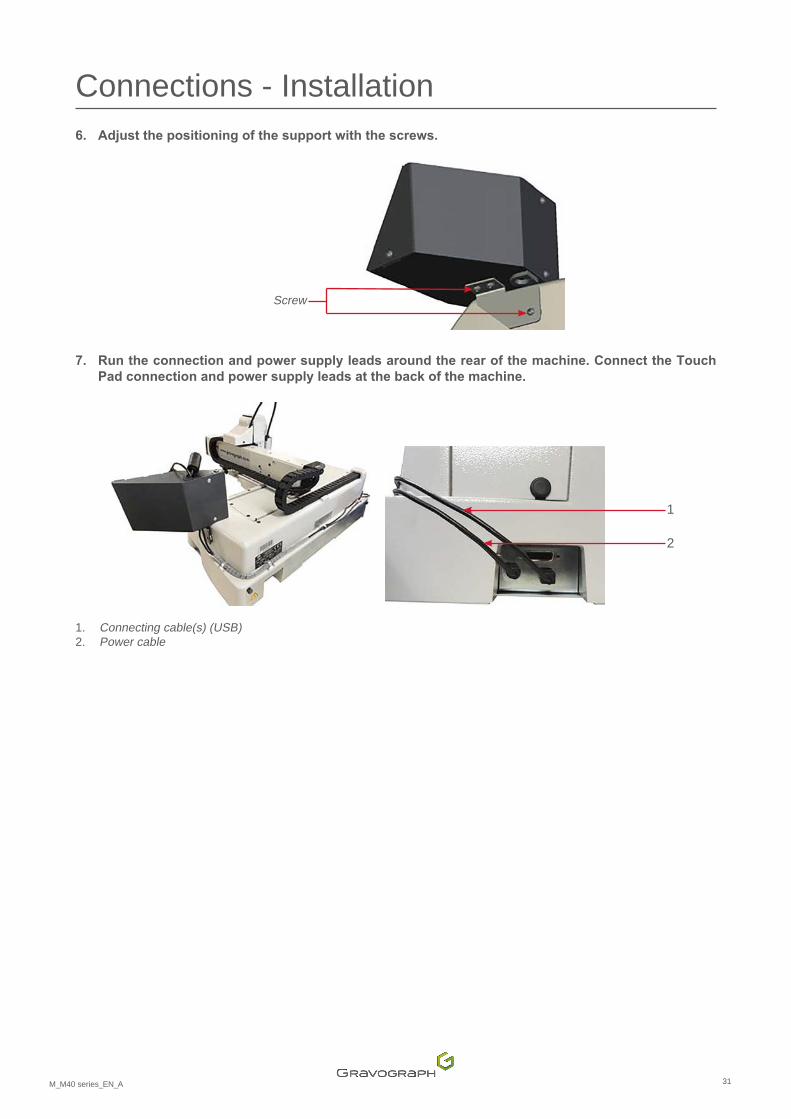
Connections - Installation 6. Adjustthepositioningofthesupportwiththescrews.
Screw
7. Run the connection and power supply leads around the rear of the machine. Connect the Touch Pad connection and power supply leads at the back of the machine.
1
2
1. Connecting cable(s) (USB)2. Power cable
32M_M40 series_EN_A
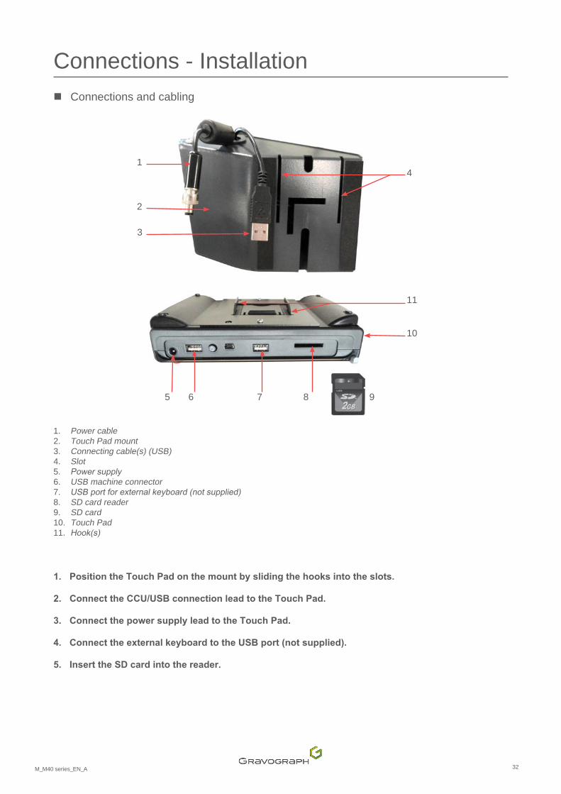
Connections - Installation � Connections and cabling
1
2
4
11
10
5 6 7 8 9
3
1. Power cable 2. Touch Pad mount 3. Connecting cable(s) (USB)4. Slot 5. Powersupply6. USB machine connector 7. USBportforexternalkeyboard(notsupplied)8. SD card reader 9. SD card 10. Touch Pad11. Hook(s)
1. Position the Touch Pad on the mount by sliding the hooks into the slots.
2. Connect the CCU/USB connection lead to the Touch Pad.
3. Connect the power supply lead to the Touch Pad.
4. Connect the external keyboard to the USB port (not supplied).
5. Insert the SD card into the reader.
33M_M40 series_EN_A
Connections - Installation 4. Installation
� Switching on the machine
1. Machine:placetheswitchinthe"I"position(On).
The machine emits an audible signal.
The power LED lights up.
• M40 ABC: switch on the Touch Pad by pressing and holding the Start/Stop button.
Always switch on the machine before starting up the Touch Pad.
Leave the machine powered on, even if it is only going to be used at intervals.
� Resolution of the problems
If the machine does not switch on:
• Checkthatthepowercordiscorrectlypluggedintoboththemachineandthepowersupply.
• Checkthatthereispowertothemainsplug.
• Checktheconditionofthefuse(See:Changing the fuse.
If the machine emits a long beep followed by a short beep and there is no movement, call a Gravotech technician.
� Power down
1. Setthegeneralstopbuttontothe"O"(Stop)position.
M40 ABC: alwaysswitchofftheTouchPadbeforepoweringdownthemachine.
Switchoffthemachineinthefollowingsituations:
• whentheoperatorispermanentlyleavingthemachine
• in theeventofphysicaldamage (something isdroppedon themachine,fire,a liquid isspilledon themachine, etc.)
• mechanical/electrical/electronicfaultssuggestingabreakdown
• ifthereisamajorproblemorthemachineisjammedmechanically
• themachineisjammedontheparttobeengraved/marked
• themachineisjammedonanobjectintheworkarea
• forced restart
• external/internal cleaning

34M_M40 series_EN_A
Connections - Installation � Restarting
Ifthemachineortheoperatingprogramlocks,themachinemayneedtoberestarted.
1. Switchoffthemachine.
2. Wait approximately 30 s.
Thiswaitingtimemustberespected.Itpreventsanelectricsurgelikelytodamagethemachine'spowersupply.
3. Switch on the machine.
� Program installation
Refer to the user manual for the program.
35M_M40 series_EN_A
J. Using the machine
1. Transfer of the composition to the machine
1. Switch on the machine.
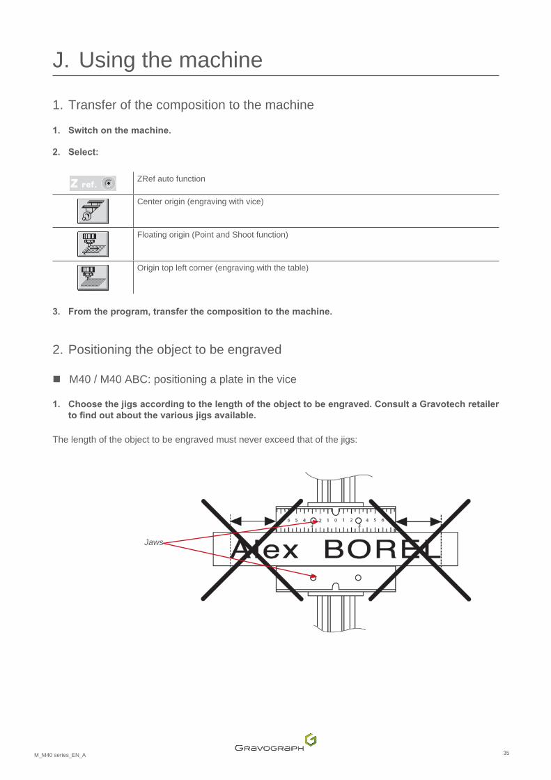
2. Select:
ZRef auto function
Center origin (engraving with vice)
Floating origin (Point and Shoot function)
Origin top left corner (engraving with the table)
3. From the program, transfer the composition to the machine.
2. Positioning the object to be engraved
� M40 / M40 ABC: positioning a plate in the vice
1. Choosethejigsaccordingtothelengthoftheobjecttobeengraved.ConsultaGravotechretailertofindoutaboutthevariousjigsavailable.
The length of the object to be engraved must never exceed that of the jigs:
Jaws
36M_M40 series_EN_A
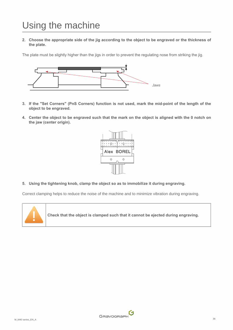
Using the machine 2. Choosetheappropriatesideofthejigaccordingtotheobjecttobeengravedorthethicknessof
the plate.
Theplatemustbeslightlyhigherthanthejigsinordertopreventtheregulatingnosefromstrikingthejig.
3. Ifthe"SetCorners"(PnSCorners)functionisnotused,markthemid-pointofthelengthoftheobjecttobeengraved.
4. Centertheobjecttobeengravedsuchthatthemarkontheobjectisalignedwiththe0notchonthejaw(centerorigin).
5. Usingthetighteningknob,clamptheobjectsoastoimmobilizeitduringengraving.
Correct clamping helps to reduce the noise of the machine and to minimize vibration during engraving.
Checkthattheobjectisclampedsuchthatitcannotbeejectedduringengraving.
Jaws
37M_M40 series_EN_A
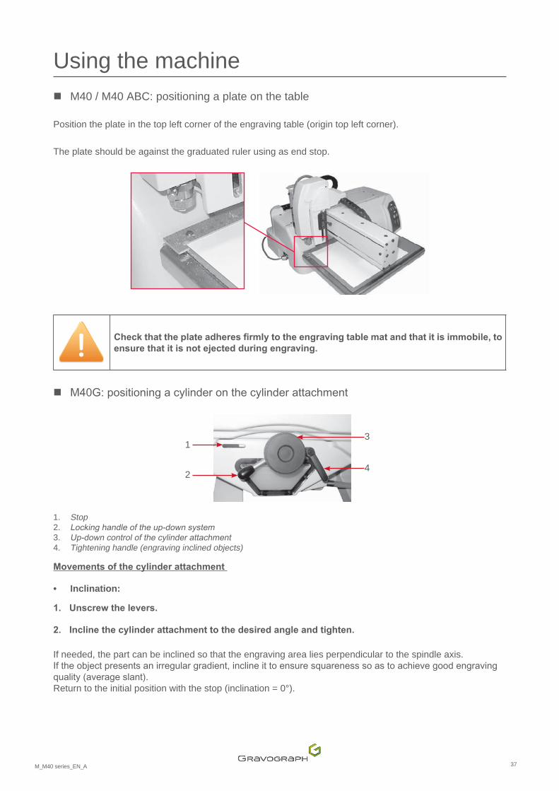
Using the machine � M40 / M40 ABC: positioning a plate on the table
Position the plate in the top left corner of the engraving table (origin top left corner).
The plate should be against the graduated ruler using as end stop.
Checkthattheplateadheresfirmlytotheengravingtablematandthatitisimmobile,toensurethatitisnotejectedduringengraving.
� M40G:positioningacylinderonthecylinderattachment
1
2
3
4
1. Stop 2. Lockinghandleoftheup-downsystem3. Up-downcontrolofthecylinderattachment4. Tightening handle (engraving inclined objects)
Movements of the cylinder attachment
• Inclination:
1. Unscrew the levers.
2. Incline the cylinder attachment to the desired angle and tighten.
If needed, the part can be inclined so that the engraving area lies perpendicular to the spindle axis. Iftheobjectpresentsanirregulargradient,inclineittoensuresquarenesssoastoachievegoodengravingquality(averageslant). Return to the initial position with the stop (inclination = 0°).

38M_M40 series_EN_A
Using the machine • Raising/lowering system of the cylinder attachment:
1. Unscrew the levers.
2. Actuate the thumbwheel to raise or lower the cylinder attachment.
• Opening and closing the jaws:
Position of the motorized jaw opening and closing control button:
- left = opening - Right = closing
Positionthecylinderattachmentsuchthattheobjecttobeengravedisnomorethan10 mm (0.394 in) below the machine spindle. Once positioning is complete, check that the buttons and levers have been tightened.
Positioning a simple cylinder
1. Using the handle, lower the cylinder attachment as much as possible.
2. Clamptheobjecttobeengraved:
- Place the object to be engraved between the jaws. - Engagetheobjectsuchthatitisheldsecurelybytheconeorthetailstock. - Use the clamping lever to immobilize the object during engraving.
3. Usingthethumbwheel,raisetheobjecttoapositionlessthan10mm(0.394in)belowthespindle.
39M_M40 series_EN_A
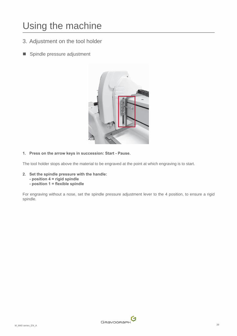
Using the machine 3. Adjustment on the tool holder
� Spindle pressure adjustment
4321
1. Pressonthearrowkeysinsuccession:Start-Pause.
The tool holder stops above the material to be engraved at the point at which engraving is to start.
2. Setthespindlepressurewiththehandle: - position 4 = rigid spindle -position1=flexiblespindle
For engraving without a nose, set the spindle pressure adjustment lever to the 4 position, to ensure a rigid spindle.
40M_M40 series_EN_A
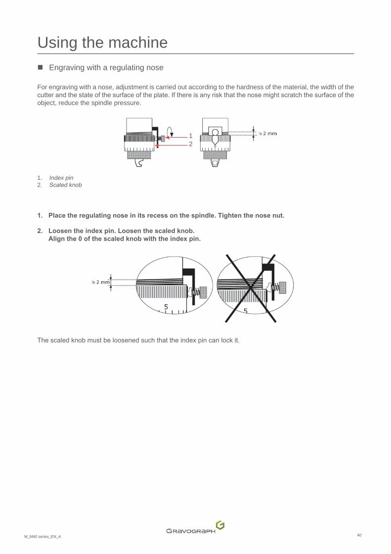
Using the machine � Engraving with a regulating nose
For engraving with a nose, adjustment is carried out according to the hardness of the material, the width of the cutterandthestateofthesurfaceoftheplate.Ifthereisanyriskthatthenosemightscratchthesurfaceoftheobject, reduce the spindle pressure.
12
1. Index pin 2. Scaledknob
1. Place the regulating nose in its recess on the spindle. Tighten the nose nut.
2. Loosen the index pin. Loosen the scaled knob. Align the 0 of the scaled knob with the index pin.
Thescaledknobmustbeloosenedsuchthattheindexpincanlockit.
41M_M40 series_EN_A
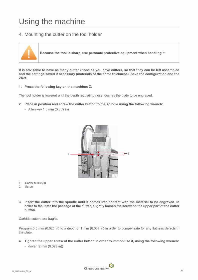
Using the machine 4. Mounting the cutter on the tool holder
Because the tool is sharp, use personal protective equipment when handling it.
It is advisable to have as many cutter knobs as you have cutters, so that they can be left assembled andthesettingssavedifnecessary(materialsofthesamethickness).SavetheconfigurationandtheZRef.
1. Pressthefollowingkeyonthemachine:Z.
The tool holder is lowered until the depth regulating nose touches the plate to be engraved.
2. Placeinpositionandscrewthecutterbuttontothespindleusingthefollowingwrench:
- Allenkey1.5mm(0.059in)
1 2
1. Cutter button(s) 2. Screw
3. Insert the cutter into the spindle until it comes into contact with the material to be engraved. In order to facilitate the passage of the cutter, slightly loosen the screw on the upper part of the cutter button.
Carbide cutters are fragile.
Program0.5mm(0.020in)toadepthof1mm(0.039in)inordertocompensateforanyflatnessdefectsinthe plate.
4. Tightentheupperscrewofthecutterbuttoninordertoimmobilizeit,usingthefollowingwrench:
- driver (2 mm (0.079 in))

42M_M40 series_EN_A
Using the machine 5. Setting the origin of the tool carrier
� M40 / M40G
StorethepositionoftheZzeropointbypressingthe"Confirm"keyfor3seconds.Themachineemitsan audible signal.
The tool holder is raised.
� M40 ABC
Storethepositionof thetoolcarrierbypressingthe"Confirm"key.Themachineemitsanaudiblesignal.
The tool holder is raised.
Thefollowingmessageisdisplayed:

43M_M40 series_EN_A
Using the machine 6. Adjusting the engraving depth
1. Turn the scaled knob a few notches to the right to obtain the desired engraving depth. 1 division(s) = 0.025 mm (0.001 in)
The number of notches depends on the engraving depth and the material: Material to be engraved Type of cutter Depth Number of notches
Anodizedaluminum carbide point 0.1 mm (0.004 in) 4Silver carbide point 0.3 mm (0.012 in) 12Chrome diamond point 0.025 mm (0.001 in) 1Gravometal carbide point 0.1 mm (0.004 in) 4Gravoply II carbide point 0.1 mm (0.004 in) 4Stainless steel diamond point 0.2 mm (0.008 in) 8Brass carbide point 0.2 mm (0.008 in) 8Metallex carbide point 0.1 mm (0.004 in) 4Gold carbide point 0.3 mm (0.012 in) 12Plastic carbide point 0.2 mm (0.008 in) 8
2. Screw the index pin in order to secure the scaled knob in this position.
3. Close the housing.

44M_M40 series_EN_A
Using the machine 7. Start-up engraving
Engraving is launched from the control panel on the machine.
1. Checkthattheobjectiscorrectlypositionedintheengravingarea.
2. Pressthekey:Start(controlpanel).
Thetoolholdermovesatasafetravelspeedtothefirstengravingpointandstartstheengraving.
Inordertoachieveafastertravelspeed,presstheStartkeyuntilthefirstengravingpointisreached.
• In the event of a problem, press the Pause button. Themachinepausesmomentarily. Toresumeengraving,presstheStartkey.
• To stop engraving completely, press one of the arrows on the joystick.
• To accelerate the travel speed of the spindle during engraving, press the Up arrow.
• To slow down the travel speed of the spindle during engraving, press the Down arrow.

45M_M40 series_EN_A
K. Preventive maintenance
1. General maintenance
Unplug the power supply plug before beginning any cleaning or maintenance operation.
The mains power cable must be replaced immediately if it is cut or crushed, cracked or a conductor is stripped bare.
Themachine'smaintenanceneedsdependonthetypeofmaterialused,thequantityofmaterialremoved,frequency of operation, environment and the effectiveness of the air extraction system. It is the user'sresponsibilitytodefinethem.
Dust and debris that accumulate on the machine's components can cause irregular or imprecise engraving, or the loss of the engraving position and the premature failure of components.
Regularlycleaningthemachineimprovesitsoperation,extendsthelifeofpartsandreducestheriskoffailure.
Recommendations:checkand,ifnecessary,cleanthemachineevery8hoursofengraving/markingorcutting.
For help, contact Gravotech.
Nointernalpartsofthemachinerequireuserintervention.Routinemaintenanceonlyinvolvesexternalcleaningof the engraving area.
Onlyfusechangescanbecarriedoutbytheuser.
To clean other parts of the machine, call a Gravotech technician.
� M40 ABC: color touch screen (Touch Pad)
Wipewithasoftclothslightlydampenedwithalcohol.Donotuseorganicsolvents.
46M_M40 series_EN_A
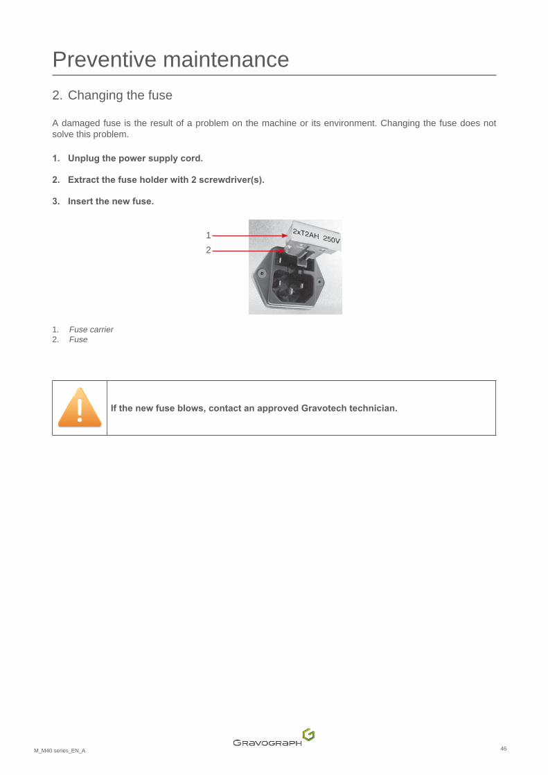
Preventive maintenance 2. Changing the fuse
A damaged fuse is the result of a problem on the machine or its environment. Changing the fuse does not solve this problem.
1. Unplug the power supply cord.
2. Extract the fuse holder with 2 screwdriver(s).
3. Insert the new fuse.
12
1. Fuse carrier 2. Fuse
If the new fuse blows, contact an approved Gravotech technician.
47M_M40 series_EN_A
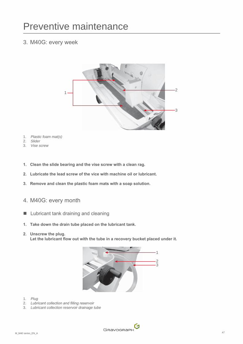
Preventive maintenance 3. M40G:everyweek
1 2
3
1. Plastic foam mat(s) 2. Slider 3. Vise screw
1. Clean the slide bearing and the vise screw with a clean rag.
2. Lubricate the lead screw of the vice with machine oil or lubricant.
3. Remove and clean the plastic foam mats with a soap solution.
4. M40G:everymonth
� Lubricanttankdrainingandcleaning
1. Take down the drain tube placed on the lubricant tank.
2. Unscrew the plug. Letthelubricantflowoutwiththetubeinarecoverybucketplacedunderit.
1
32
1. Plug 2. Lubricantcollectionandfillingreservoir3. Lubricant collection reservoir drainage tube
48M_M40 series_EN_A
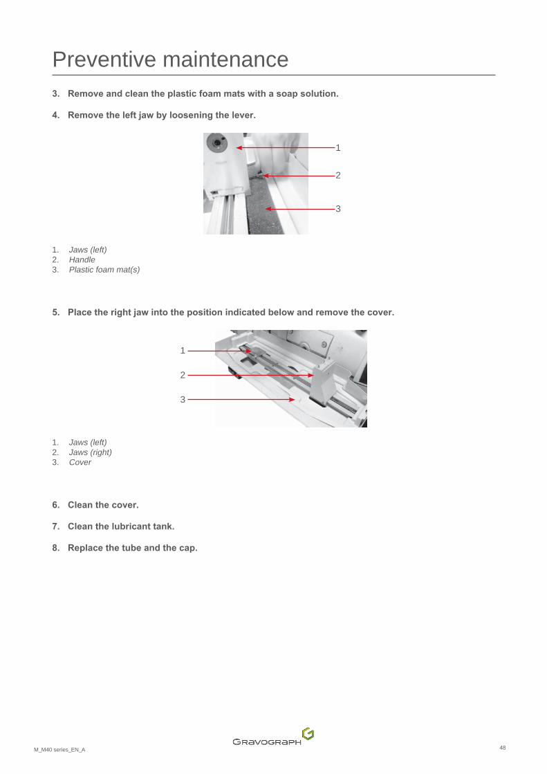
Preventive maintenance 3. Remove and clean the plastic foam mats with a soap solution.
4. Removetheleftjawbylooseningthelever.
1
3
2
1. Jaws (left)2. Handle 3. Plastic foam mat(s)
5. Placetherightjawintothepositionindicatedbelowandremovethecover.
1
2
3
1. Jaws (left)2. Jaws (right)3. Cover
6. Clean the cover.
7. Clean the lubricant tank.
8. Replace the tube and the cap.
49M_M40 series_EN_A
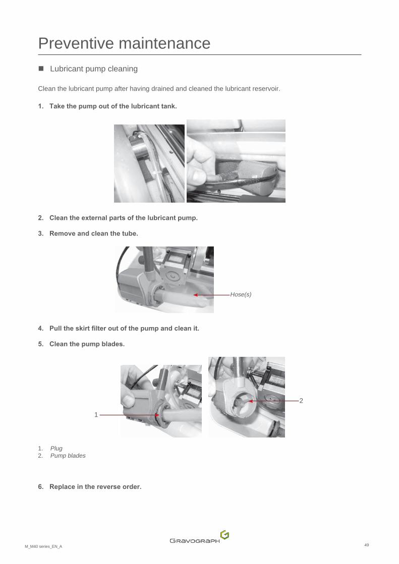
Preventive maintenance � Lubricant pump cleaning
Clean the lubricant pump after having drained and cleaned the lubricant reservoir.
1. Take the pump out of the lubricant tank.
2. Clean the external parts of the lubricant pump.
3. Remove and clean the tube.
Hose(s)
4. Pulltheskirtfilteroutofthepumpandcleanit.
5. Clean the pump blades.
2
1
1. Plug 2. Pump blades
6. Replace in the reverse order.
50M_M40 series_EN_A
Preventive maintenance 5. Adjusting the machine
Thecenteroftheengravingareaofthemachinemustbealignedwiththeclampingsystem.
TheM40seriesmachineshaveamachinereferencepointadjustmentsystemwhichcanbedeployedbytheuser.
M40ABC:torestorethefactory-setzeropointoftheSDcard,consulttheusermanualfortheprogram.
Adjustthesesettingsevery3monthsorwheneverthemachinehasbeenmoved.
1. Switch on the machine.
2. Presssimultaneouslyonthekeys:Pause-Leftarrow.
� Setting the table zero point (function not available for the M40G machine)
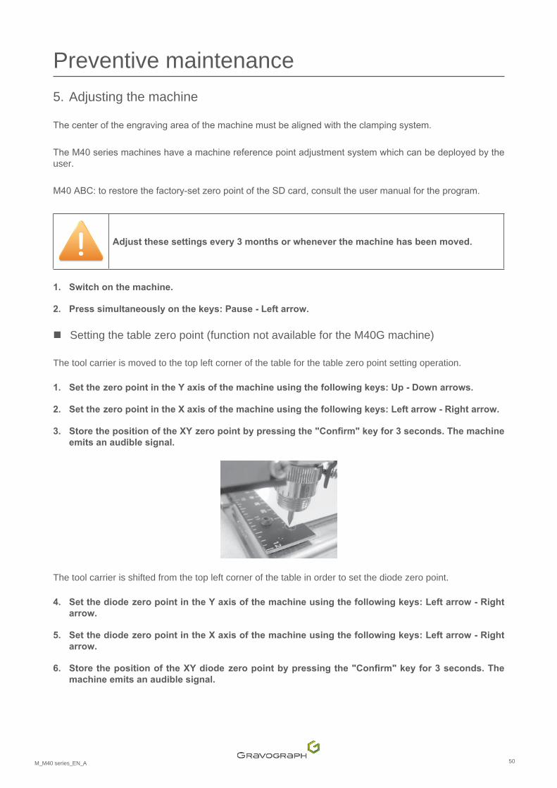
The tool carrier is moved to the top left corner of the table for the table zero point setting operation.
1. SetthezeropointintheYaxisofthemachineusingthefollowingkeys:Up-Downarrows.
2. SetthezeropointintheXaxisofthemachineusingthefollowingkeys:Leftarrow-Rightarrow.
3. StorethepositionoftheXYzeropointbypressingthe"Confirm"keyfor3seconds.Themachineemits an audible signal.
The tool carrier is shifted from the top left corner of the table in order to set the diode zero point.
4. SetthediodezeropointintheYaxisofthemachineusingthefollowingkeys:Leftarrow-Rightarrow.
5. SetthediodezeropointintheXaxisofthemachineusingthefollowingkeys:Leftarrow-Rightarrow.
6. StorethepositionoftheXYdiodezeropointbypressingthe"Confirm"keyfor3seconds.Themachine emits an audible signal.
51M_M40 series_EN_A
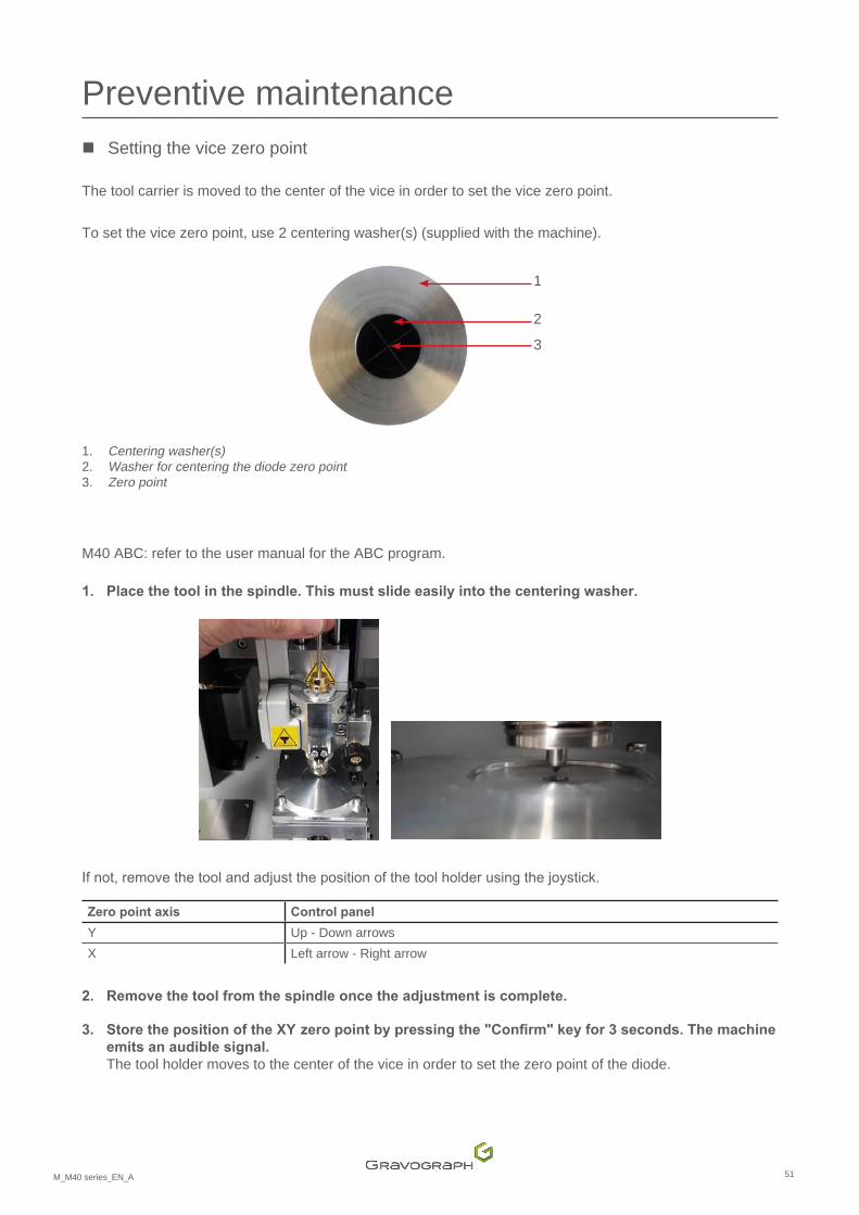
Preventive maintenance � Setting the vice zero point
The tool carrier is moved to the center of the vice in order to set the vice zero point.
To set the vice zero point, use 2 centering washer(s) (supplied with the machine).
1
2
3
1. Centering washer(s) 2. Washer for centering the diode zero point 3. Zero point
M40 ABC: refer to the user manual for the ABC program.
1. Place the tool in the spindle. This must slide easily into the centering washer.
Ifnot,removethetoolandadjustthepositionofthetoolholderusingthejoystick.
Zero point axis Control panel
Y Up - Down arrows X Left arrow - Right arrow
2. Removethetoolfromthespindleoncetheadjustmentiscomplete.
3. StorethepositionoftheXYzeropointbypressingthe"Confirm"keyfor3seconds.Themachineemits an audible signal. The tool holder moves to the center of the vice in order to set the zero point of the diode.

52M_M40 series_EN_A
Preventive maintenance 4. Fitthediodezeropointcenteringwasherintothecenteringwasherlocatingposition.
5. SetthediodezeropointintheXaxisofthemachineusingthefollowingkeys:Leftarrow-Rightarrow.
Itmustbepositionedinthemiddleofthecenteringdisk.
6. Store thepositionof theXdiodezeropointbypressing the"Confirm"key for3seconds.Themachine emits an audible signal.
� Adjusting the machine in Z
1. Switch on the machine.
2. Use the spindle with a nose, without a cutter and without pressure (position 1).
3. Presssimultaneouslyonthekeys:Pause-ZRef.
M40 ABC: refer to the user manual for the ABC program.
The tool carrier moves to the center of the vice or table.
The spindle moves down until the depth regulating nose touches the plate.
4. SetthezeropointintheZaxisofthemachineusingthefollowingkeys:Up-Downarrows.
5. StorethepositionoftheZzeropointbypressingthe"Confirm"keyfor3seconds.Themachineemits an audible signal.
� M40 ABC
It is possible to restore a previously set zero point that has been saved to aSD card (suppliedwith themachine).
Savethesesettings.Theyarespecifictoeachmachine.
The new settings must be saved to another SD card.
Refer to the user manual for the ABC program.
53M_M40 series_EN_A
L. Technicalspecifications
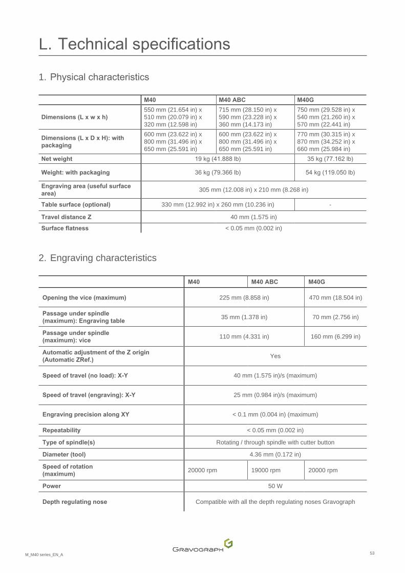
1. Physicalcharacteristics
M40 M40 ABC M40G
Dimensions (L x w x h) 550 mm (21.654 in) x 510 mm (20.079 in) x 320 mm (12.598 in)
715 mm (28.150 in) x 590 mm (23.228 in) x 360 mm (14.173 in)
750 mm (29.528 in) x 540 mm (21.260 in) x 570 mm (22.441 in)
Dimensions(LxDxH):withpackaging
600 mm (23.622 in) x 800 mm (31.496 in) x 650 mm (25.591 in)
600 mm (23.622 in) x 800 mm (31.496 in) x 650 mm (25.591 in)
770 mm (30.315 in) x 870 mm (34.252 in) x 660 mm (25.984 in)
Net weight 19kg(41.888lb) 35kg(77.162lb)
Weight:withpackaging 36kg(79.366lb) 54kg(119.050lb)
Engraving area (useful surface area)
305 mm (12.008 in) x 210 mm (8.268 in)
Table surface (optional) 330 mm (12.992 in) x 260 mm (10.236 in) -
Travel distance Z 40 mm (1.575 in)
Surfaceflatness < 0.05 mm (0.002 in)
2. Engraving characteristics
M40 M40 ABC M40G
Opening the vice (maximum) 225 mm (8.858 in) 470 mm (18.504 in)
Passage under spindle (maximum):Engravingtable
35 mm (1.378 in) 70 mm (2.756 in)
Passage under spindle (maximum):vice
110 mm (4.331 in) 160 mm (6.299 in)
AutomaticadjustmentoftheZorigin(Automatic ZRef.)
Yes
Speedoftravel(noload):X-Y 40 mm (1.575 in)/s (maximum)
Speedoftravel(engraving):X-Y 25 mm (0.984 in)/s (maximum)
EngravingprecisionalongXY < 0.1 mm (0.004 in) (maximum)
Repeatability < 0.05 mm (0.002 in)
Type of spindle(s) Rotating / through spindle with cutter button
Diameter (tool) 4.36 mm (0.172 in)
Speed of rotation (maximum)
20000 rpm 19000 rpm 20000 rpm
Power 50 W
Depth regulating nose Compatible with all the depth regulating noses Gravograph
54M_M40 series_EN_A
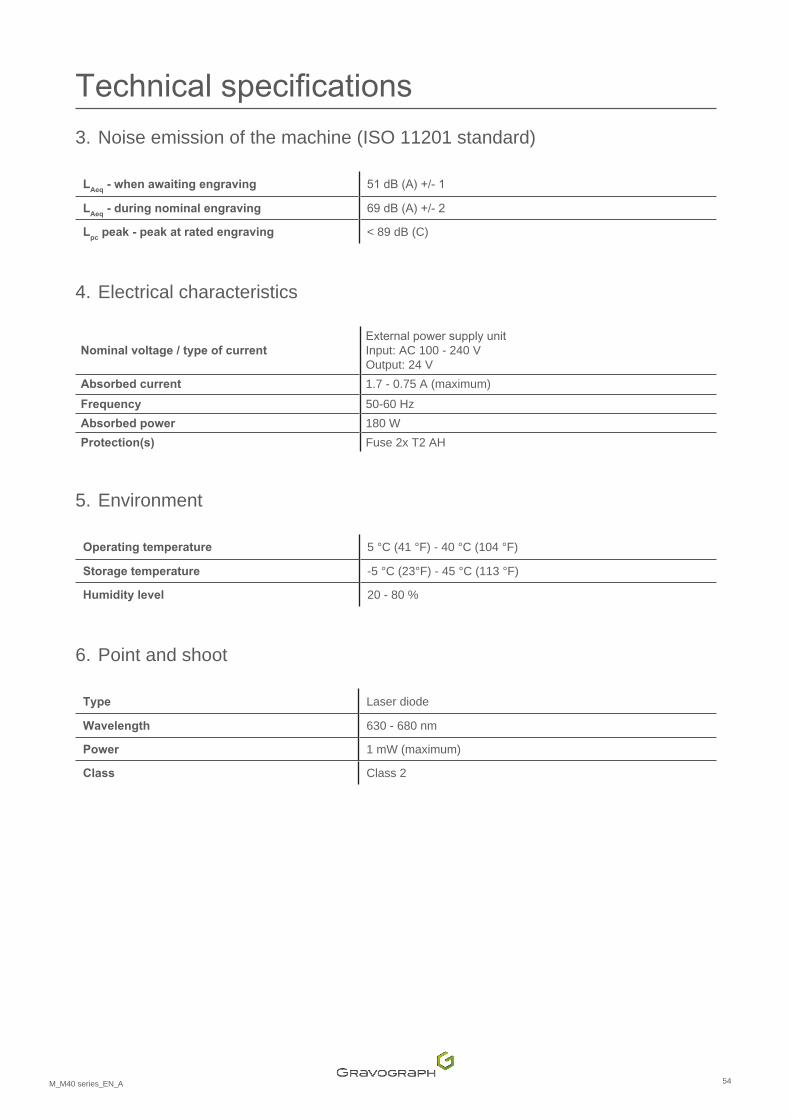
Technicalspecifications3. Noise emission of the machine (ISO 11201 standard)
LAeq
- when awaiting engraving 51dB(A)+/-1
LAeq
- during nominal engraving 69dB(A)+/-2
Lpc
peak - peak at rated engraving < 89 dB (C)
4. Electrical characteristics
Nominal voltage / type of current ExternalpowersupplyunitInput: AC 100 - 240 VOutput: 24 V
Absorbed current 1.7 - 0.75 A (maximum)Frequency 50-60 HzAbsorbed power 180 WProtection(s) Fuse 2x T2 AH
5. Environment
Operating temperature 5 °C (41 °F) - 40 °C (104 °F)
Storage temperature -5 °C (23°F) - 45 °C (113 °F)
Humidity level 20 - 80 %
6. Point and shoot
Type Laser diode
Wavelength 630 - 680 nm
Power 1 mW (maximum)
Class Class 2
55M_M40 series_EN_A
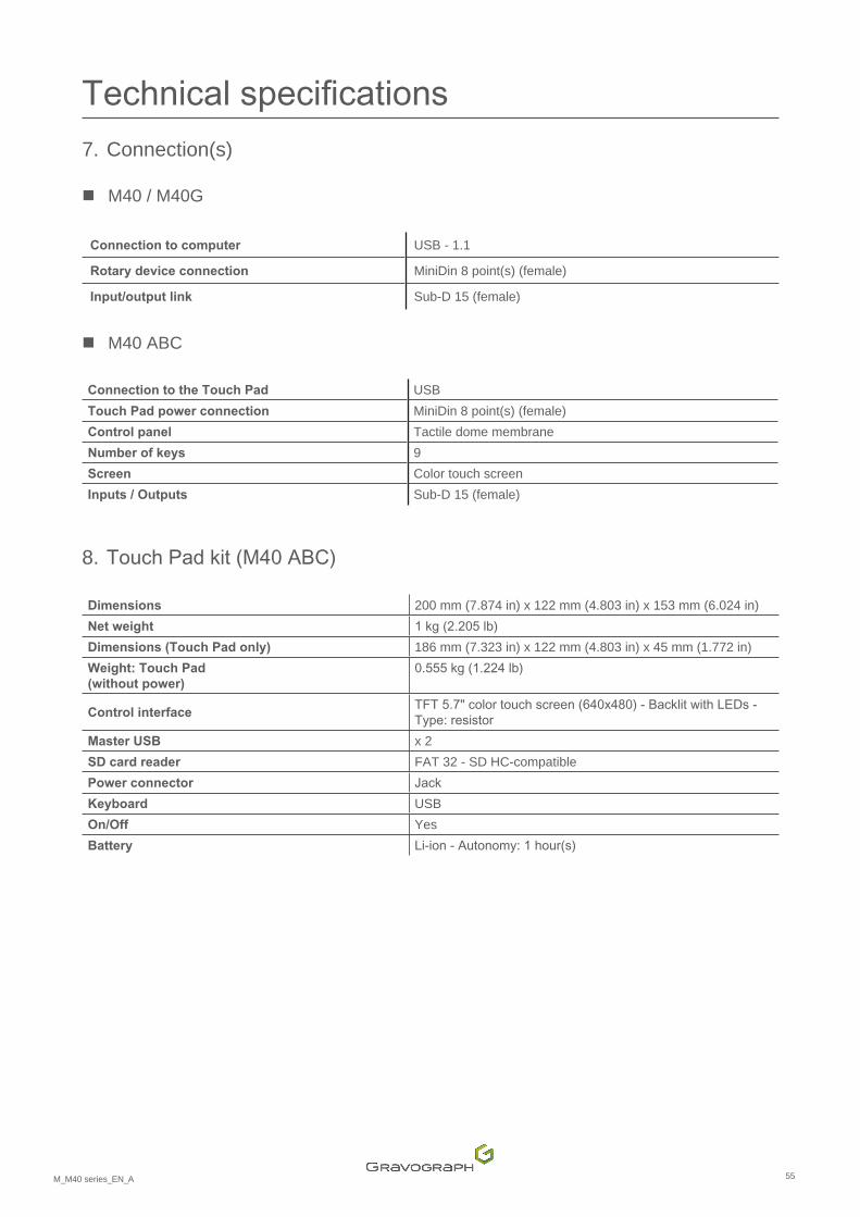
Technicalspecifications7. Connection(s)
� M40 / M40G
Connection to computer USB - 1.1
Rotary device connection MiniDin 8 point(s) (female)
Input/output link Sub-D 15 (female)
� M40 ABC
Connection to the Touch Pad USBTouch Pad power connection MiniDin 8 point(s) (female)Control panel Tactile dome membrane Number of keys 9Screen Color touch screen Inputs / Outputs Sub-D 15 (female)
8. TouchPadkit(M40ABC)
Dimensions 200 mm (7.874 in) x 122 mm (4.803 in) x 153 mm (6.024 in)Net weight 1kg(2.205lb)Dimensions (Touch Pad only) 186 mm (7.323 in) x 122 mm (4.803 in) x 45 mm (1.772 in)Weight:TouchPad(without power)
0.555kg(1.224lb)
Control interface TFT5.7"colortouchscreen(640x480)-BacklitwithLEDs-Type:resistor
Master USB x 2SD card reader FAT 32 - SD HC-compatible Power connector JackKeyboard USBOn/Off Yes Battery Li-ion-Autonomy:1hour(s)
56M_M40 series_EN_A
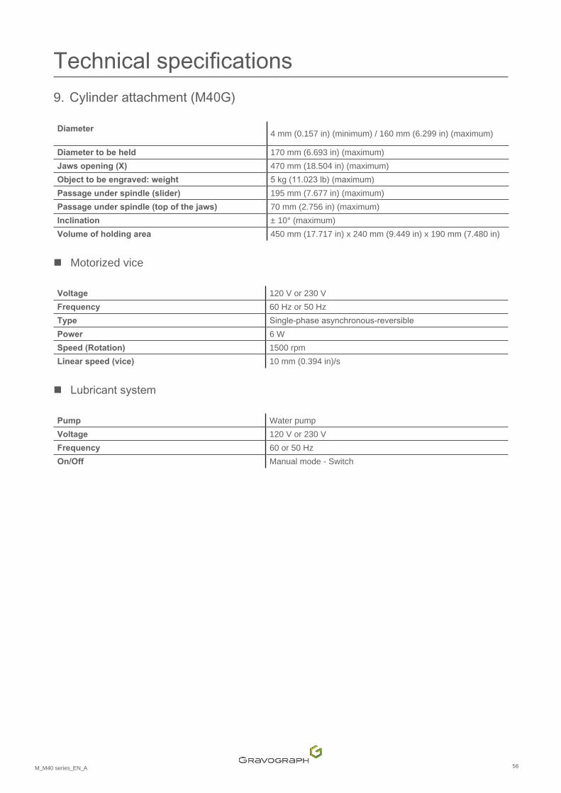
Technicalspecifications9. Cylinderattachment(M40G)
Diameter 4 mm (0.157 in) (minimum) / 160 mm (6.299 in) (maximum)
Diameter to be held 170 mm (6.693 in) (maximum)Jawsopening(X) 470 mm (18.504 in) (maximum)Objecttobeengraved:weight 5kg(11.023lb)(maximum)Passage under spindle (slider) 195 mm (7.677 in) (maximum)Passageunderspindle(topofthejaws) 70 mm (2.756 in) (maximum)Inclination ± 10° (maximum)Volume of holding area 450 mm (17.717 in) x 240 mm (9.449 in) x 190 mm (7.480 in)
� Motorized vice
Voltage 120 V or 230 VFrequency 60 Hz or 50 HzType Single-phaseasynchronous-reversiblePower 6 WSpeed (Rotation) 1500 rpmLinear speed (vice) 10 mm (0.394 in)/s
� Lubricantsystem
Pump Water pump Voltage 120 V or 230 VFrequency 60 or 50 HzOn/Off Manual mode - Switch