Embed Size (px)
Citation preview

M61PMV Series Motherboard
User’s Manual

Statement:This manual is the intellectual property of Foxconn, Inc. Although the information in this manual may be changed or modified at any time, Foxconn does not obligate
itself to inform the user of these changes.
Trademark:All trademarks are the property of their respective owners.
Version:User’s Manual V1.3 for M61PMV Series motherboard.
Symbol description:
Caution : refers to important information that can help you to use motherboard better, and tells you how to avoid problems.
Warning : indicating a potential risk of hardware damage or physical injury
may exist.
WEEE:
The use of this symbol indicates that this product may not be treated as household waste. By ensuring this product is disposed of correctly, you will help prevent potential negative consequences for the environment and human health, which could other-wise be caused by inappropriate waste handling of this product. For more detailed information about recycling of this product, please contact your local city office, your
household waste disposal service or the shop where you purchased this product.
More information:If you want more information about our products, please visit Foxconn’swebsite: http://www.foxconnchannel.com
CAUT
ION
!WARNING!
© All rights reserved.All trade names are registered trademarks of respective manufacturers listed.
All images are for reference only, please refer to the physical motherboard for specific features.

Declaration of conformity
HON HAI PRECISION INDUSTRY COMPANY LTD66 , CHUNG SHAN RD., TU-CHENG INDUSTRIAL DISTRICT,
TAIPEI HSIEN, TAIWAN, R.O.C.
declares that the productMotherboard M61PMV/ M61PMV-E/ M61PMVK
is in conformity with(reference to the specification under which conformity is declared in
accordance with 89/336 EEC-EMC Directive)
■ EN 55022:1998/A2: 2003 Limits and methods of measurements of radio disturbance characteristics of information technology equipment
■ EN 61000-3-2/:2000 Electromagnetic compatibility (EMC) Part 3: Limits Section 2: Limits for harmonic current emissions (equipment input current <= 16A per phase)
■ EN 61000-3-3/A1:2001 Electromagnetic compatibility (EMC) Part 3: Limits Section 2: Limits of voltage fluctuations and flicker in low voltage supply systems for equipment with rated current <= 16A
■ EN 55024/A2:2003 Information technology equipment-Immunity characteristics limits and methods of measurement
Signature : Place / Date : TAIPEI/2009
Printed Name : James Liang

Declaration of conformity
Trade Name: FOXCONN
Model Name: M61PMV/ M61PMV-E/ M61PMVK Responsible Party: PCE Industry Inc.
Address: 458 E. Lambert Rd. Fullerton, CA 92835
Telephone: 714-738-8868 Facsimile: 714-738-8838
Equipment Classification: FCC Class B Subassembly Type of Product: Motherboard
Manufacturer: HON HAI PRECISION INDUSTRY COMPANY LTD
Address: 66 , CHUNG SHAN RD., TU-CHENG INDUSTRIAL DISTRICT, TAIPEI HSIEN, TAIWAN, R.O.C.
Supplementary Information:
This device complies with Part 15 of the FCC Rules. Operation is subject to the following two conditions : (1) this device may not cause harmful interference, and (2) this device must accept any interference received, including interference that may cause undesired operation.Tested to comply with FCC standards.
Signature : Date : 2009
Please carefully read the following procedures to install your computer :■ It is suggested to select high-quality, certified fans in order to avoid damage
to the motherboard and CPU due to high temperature. Never turn on the computer if the CPU fan is not properly installed.
■ We cannot guarantee that your system can operate normally when your CPU is overclocked. Normal operation depends on the overclocking capac-ity of your device.
■ If there is any, when connecting USB, audio, RS232 COM, IrDA or S/PDIF cables to the internal connectors on the motherboard, make sure their pinouts are matching with the connectors on the motherboard. Incorrect con-nections might damage the motherboard.
■ When handling the motherboard, avoid touching any metal leads or connec-tors.
■ If there is a PCI Express x16 graphics card installed in your system, we recommend using a 24-pin ATX power supply to get the best performance.
■ Before turning on the power, please make sure the power supply AC input voltage setting has been configured to the local standard.
■ To prevent damage to the motherboard, do not allow screws to come in contact with the motherboard circuit or its components. Also, make sure there are no leftover screws or metal components placed on the motherboard or within the computer casing.
■ If you are uncertain about any installation steps or have a problem related to the use of the product, please consult a certified computer technician.
CAUT
ION
!
Installation Precautions
■ Electrostatic discharge (ESD) is the sudden and momentary electric current that flows between two objects at different electrical potentials. Normally it comes out as a spark which will quickly damage your electronic equipment. Please wear an electrostatic discharge (ESD) wrist strap when handling components such as a motherboard, CPU or memory.
■ Ensure that the DC power supply is turned off before installing or removing CPU, memory, expansion cards or other peripherals. It is recommended to unplug the AC power cord from the power supply outlet. Failure to unplug the power supply cord may result in serious damage to your system.
WARNING!
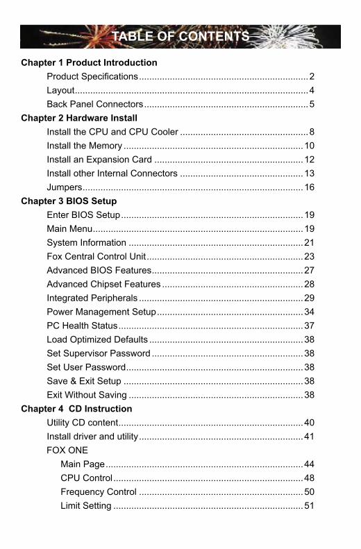
TAble of CoNTeNTS
Chapter 1 Product Introduction Product Specifications ..................................................................2 Layout ...........................................................................................4 Back Panel Connectors ................................................................5Chapter 2 Hardware Install Install the CPU and CPU Cooler ..................................................8 Install the Memory ......................................................................10 Install an Expansion Card ..........................................................12 Install other Internal Connectors ................................................13 Jumpers ......................................................................................16Chapter 3 bIoS Setup Enter BIOS Setup .......................................................................19 Main Menu ..................................................................................19 System Information ....................................................................21 Fox Central Control Unit .............................................................23 Advanced BIOS Features ...........................................................27 Advanced Chipset Features .......................................................28 Integrated Peripherals ................................................................29 Power Management Setup .........................................................34 PC Health Status ........................................................................37 Load Optimized Defaults ............................................................38 Set Supervisor Password ...........................................................38 Set User Password .....................................................................38 Save & Exit Setup ......................................................................38 Exit Without Saving ....................................................................38Chapter 4 CD Instruction Utility CD content ........................................................................40 Install driver and utility ................................................................41 FOX ONE Main Page .............................................................................44 CPU Control ..........................................................................48 Frequency Control ................................................................50 Limit Setting ..........................................................................51
Voltage Control .....................................................................53 Fan Control ...........................................................................54 FOX LiveUpdate Local Update .........................................................................55 Online Update .......................................................................57 Configure .............................................................................60 About & Help .........................................................................62 FOX LOGO .................................................................................63 FOX DMI ....................................................................................64Chapter 5 RAID Configuration RAID Configuration Introduction .................................................67 NVIDIA® MediaShield Driver .....................................................69 Create two RAID Driver Diskettes ..............................................71 RAID Enable in BIOS .................................................................73 Select a RAID Array for Use .......................................................73 Install a New Windows XP..........................................................89 Setting Up a Non-Bootable RAID Array ......................................96
Technical Support :
Website :http://www.foxconnchannel.com
Support Website :http://www.foxconnsupport.com
Worldwide online Contact Support :http://www.foxconnchannel.com/support/online.aspx
CPU, Memory, VGA Compatibility Supporting Website :http://www.foxconnchannel.com/support/online.aspx
Support

Thank you for buying Foxconn M61PMV Series motherboard. Foxconn products are engineered to maximize computing power, providing only what you need for break-through performance.
With advanced overclocking capability and a range of connectivity features for today multi-media computing requirements, M61PMV /M61PMV-E/M61PMVK enables you to unleash more power from your computer.
This chapter includes the following information:■ Product Specifications■ Layout■ Back Panel Connectors
1
2
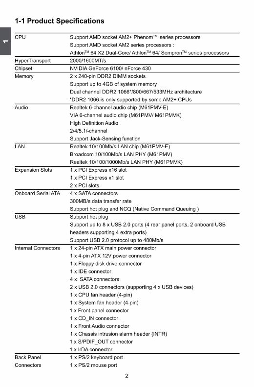
1-1 Product Specifications
CPU Support AMD socket AM2+ PhenomTM series processors Support AMD socket AM2 series processors : AthlonTM 64 X2 Dual-Core/ AthlonTM 64/ SempronTM series processorsHyperTransport 2000/1600MT/s Chipset NVIDIA GeForce 6100/ nForce 430 Memory 2 x 240-pin DDR2 DIMM sockets Support up to 4GB of system memory Dual channel DDR2 1066*/800/667/533MHz architecture *DDR2 1066 is only supported by some AM2+ CPUs Audio Realtek 6-channel audio chip (M61PMV-E) VIA 6-channel audio chip (M61PMV/ M61PMVK) High Definition Audio 2/4/5.1/-channel Support Jack-Sensing functionLAN Realtek 10/100Mb/s LAN chip (M61PMV-E) Broadcom 10/100Mb/s LAN PHY (M61PMV) Realtek 10/100/1000Mb/s LAN PHY (M61PMVK) Expansion Slots 1 x PCI Express x16 slot 1 x PCI Express x1 slot 2 x PCI slotsOnboard Serial ATA 4 x SATA connectors 300MB/s data transfer rate Support hot plug and NCQ (Native Command Queuing )USB Support hot plug Support up to 8 x USB 2.0 ports (4 rear panel ports, 2 onboard USB headers supporting 4 extra ports) Support USB 2.0 protocol up to 480Mb/sInternal Connectors 1 x 24-pin ATX main power connector 1 x 4-pin ATX 12V power connector 1 x Floppy disk drive connector 1 x IDE connector 4 x SATA connectors 2 x USB 2.0 connectors (supporting 4 x USB devices) 1 x CPU fan header (4-pin) 1 x System fan header (4-pin) 1 x Front panel connector 1 x CD_IN connector 1 x Front Audio connector 1 x Chassis intrusion alarm header (INTR) 1 x S/PDIF_OUT connector 1 x IrDA connectorBack Panel 1 x PS/2 keyboard portConnectors 1 x PS/2 mouse port
1
3
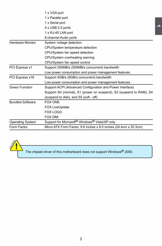
1 x VGA port 1 x Parallel port 1 x Serial port 4 x USB 2.0 ports 1 x RJ-45 LAN port 6-channel Audio ports Hardware Monitor System voltage detection CPU/System temperature detection CPU/System fan speed detection CPU/System overheating warning CPU/System fan speed controlPCI Express x1 Support 250MB/s (500MB/s concurrent) bandwidth Low power consumption and power management featuresPCI Express x16 Support 4GB/s (8GB/s concurrent) bandwidth Low power consumption and power management featuresGreen Function Support ACPI (Advanced Configuration and Power Interface) Support S0 (normal), S1 (power on suspend), S3 (suspend to RAM), S4
(suspend to disk), and S5 (soft - off)Bundled Software FOX ONE FOX LiveUpdate FOX LOGO FOX DMIOperating System Support for Microsoft® Windows® Vista/XP onlyForm Factor Micro ATX Form Factor, 9.6 inches x 8.0 inches (24.4cm x 20.3cm)
The chipset driver of this motherboard does not support Windows® 2000.
CAUT
ION
!
1
4
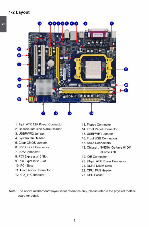
1-2 layout
12
23
1
14
11
1. 4-pin ATX 12V Power Connector2. Chassis Intrusion Alarm Header3. USBPWR2 Jumper4. System fan Header 5. Clear CMOS Jumper6. S/PDIF Out Connector7. IrDA Connector8. PCI Express x16 Slot9. PCI Express x1 Slot10. PCI Slots11. Front Audio Connector12. CD_IN Connector
13. Floppy Connector14. Front Panel Connector 15. USBPWR1 Jumper16. Front USB Connectors17. SATA Connectors18. Chipset : NVIDIA Geforce 6100/ nForce 43019. IDE Connector20. 24-pin ATX Power Connector21. DDR2 DIMM Slots22. CPU_FAN Header23. CPU Socket
Note : The above motherboard layout is for reference only, please refer to the physical mother-board for detail.
16
13
21
5910 3 24678
15
17 19 2018
22
1
5
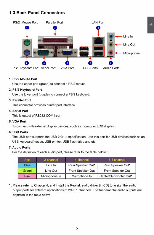
1-3 back Panel Connectors
1. PS/2 Mouse PortUse the upper port (green) to connect a PS/2 mouse.
2. PS/2 Keyboard PortUse the lower port (purple) to connect a PS/2 keyboard.
3. Parallel PortThis connector provides printer port interface.
4. Serial PortThis is output of RS232 COM1 port.
5. VGA PortTo connect with external display devices, such as monitor or LCD display.
6. USb PortsThe USB port supports the USB 2.0/1.1 specification. Use this port for USB devices such as an USB keyboard/mouse, USB printer, USB flash drive and etc.
7. Audio PortsFor the definition of each audio port, please refer to the table below :
* : Please refer to Chapter 4, and install the Realtek audio driver (in CD) to assign the audio output ports for different applications of 2/4/5.1 channels. The fundamental audio outputs are depicted in the table above.
USB Ports
LAN PortParallel Port
PS/2 Keyboard Port
PS/2 Mouse Port
7
1 3
Audio Ports
8
VGA Port4 52 6
Line Out
Microphone
Line In
Serial Port
Port 2-channel 4-channel 5.1-channel
Blue Line In Rear Speaker Out* Rear Speaker Out*
Green Line Out Front Speaker Out Front Speaker Out
Pink Microphone In Microphone In Center/Subwoofer Out*
1
6
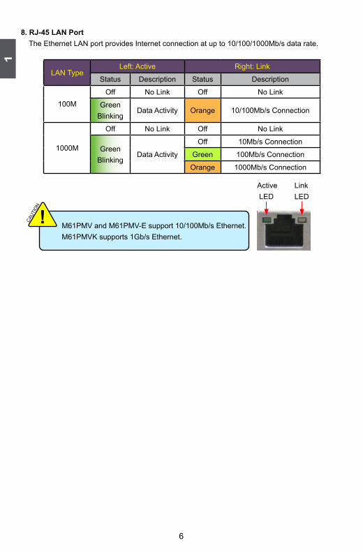
8. RJ-45 lAN PortThe Ethernet LAN port provides Internet connection at up to 10/100/1000Mb/s data rate.
LinkLED
Active LED
LAN TypeLeft: Active Right: Link
Status Description Status Description
100MOff No Link Off No Link
Green Blinking
Data Activity Orange 10/100Mb/s Connection
1000M
Off No Link Off No Link
Green Blinking
Data Activity
Off 10Mb/s Connection
Green 100Mb/s Connection
Orange 1000Mb/s Connection
M61PMV and M61PMV-E support 10/100Mb/s Ethernet.M61PMVK supports 1Gb/s Ethernet.
CAUT
ION
!
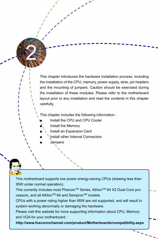
This chapter introduces the hardware installation process, including the installation of the CPU, memory, power supply, slots, pin headers and the mounting of jumpers. Caution should be exercised during the installation of these modules. Please refer to the motherboard layout prior to any installation and read the contents in this chapter carefully.
This chapter includes the following information :■ Install the CPU and CPU Cooler■ Install the Memory■ Install an Expansion Card■ Install other Internal Connectors■ Jumpers
This motherboard supports low power energy-saving CPUs (drawing less than 95W under normal operation).This currently includes most PhenomTM Series, AthlonTM 64 X2 Dual-Core pro-cessors, and all AthlonTM 64 and SempronTM models.CPUs with a power rating higher than 95W are not supported, and will result in system working abnormally or damaging the hardware.Please visit this website for more supporting information about CPU, Memory and VGA for your motherboard : http://www.foxconnchannel.com/product/Motherboards/compatibility.aspx
2
8
2-1 Install the CPU and CPU Cooler
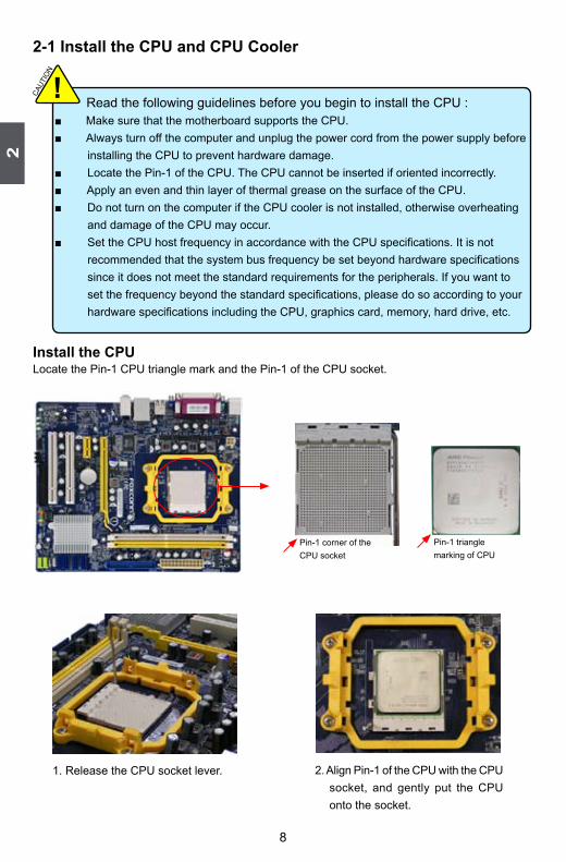
Install the CPULocate the Pin-1 CPU triangle mark and the Pin-1 of the CPU socket.
Pin-1 triangle marking of CPU
Pin-1 corner of the CPU socket
1. Release the CPU socket lever. 2. Align Pin-1 of the CPU with the CPU socket, and gently put the CPU onto the socket.
Read the following guidelines before you begin to install the CPU :■ Make sure that the motherboard supports the CPU.■ Always turn off the computer and unplug the power cord from the power supply before
installing the CPU to prevent hardware damage.■ Locate the Pin-1 of the CPU. The CPU cannot be inserted if oriented incorrectly. ■ Apply an even and thin layer of thermal grease on the surface of the CPU.■ Do not turn on the computer if the CPU cooler is not installed, otherwise overheating
and damage of the CPU may occur.■ Set the CPU host frequency in accordance with the CPU specifications. It is not
recommended that the system bus frequency be set beyond hardware specifications since it does not meet the standard requirements for the peripherals. If you want to set the frequency beyond the standard specifications, please do so according to your hardware specifications including the CPU, graphics card, memory, hard drive, etc.
CAUT
ION
!
2
9
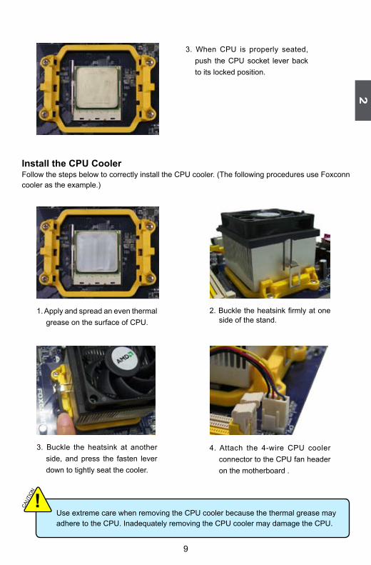
3. When CPU is properly seated, push the CPU socket lever back to its locked position.
Install the CPU CoolerFollow the steps below to correctly install the CPU cooler. (The following procedures use Foxconn cooler as the example.)
1. Apply and spread an even thermal grease on the surface of CPU.
2. Buckle the heatsink firmly at one side of the stand.
3. Buckle the heatsink at another side, and press the fasten lever down to tightly seat the cooler.
4. Attach the 4-wire CPU cooler connector to the CPU fan header on the motherboard .
Use extreme care when removing the CPU cooler because the thermal grease may adhere to the CPU. Inadequately removing the CPU cooler may damage the CPU.
CAU
TIO
N
!
2
10
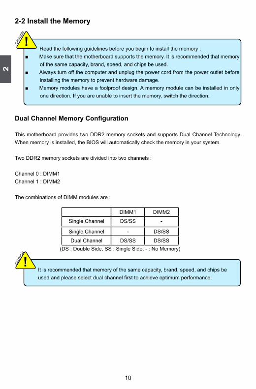
2-2 Install the Memory
Dual Channel Memory Configuration
This motherboard provides two DDR2 memory sockets and supports Dual Channel Technology. When memory is installed, the BIOS will automatically check the memory in your system.
Two DDR2 memory sockets are divided into two channels :
Channel 0 : DIMM1Channel 1 : DIMM2
The combinations of DIMM modules are :
It is recommended that memory of the same capacity, brand, speed, and chips be used and please select dual channel first to achieve optimum performance.
CAU
TIO
N
!
Read the following guidelines before you begin to install the memory :■ Make sure that the motherboard supports the memory. It is recommended that memory
of the same capacity, brand, speed, and chips be used.■ Always turn off the computer and unplug the power cord from the power outlet before
installing the memory to prevent hardware damage.■ Memory modules have a foolproof design. A memory module can be installed in only
one direction. If you are unable to insert the memory, switch the direction.
CAU
TIO
N
!
DIMM1 DIMM2
Single Channel DS/SS -
Single Channel - DS/SS
Dual Channel DS/SS DS/SS(DS : Double Side, SS : Single Side, - : No Memory)
2
11
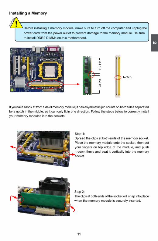
Installing a Memory
If you take a look at front side of memory module, it has asymmetric pin counts on both sides separated by a notch in the middle, so it can only fit in one direction. Follow the steps below to correctly install your memory modules into the sockets.
Step 1:Spread the clips at both ends of the memory socket. Place the memory module onto the socket, then put your fingers on top edge of the module, and push it down firmly and seat it vertically into the memory socket.
Step 2:The clips at both ends of the socket will snap into place when the memory module is securely inserted.
Before installing a memory module, make sure to turn off the computer and unplug the power cord from the power outlet to prevent damage to the memory module. Be sure to install DDR2 DIMMs on this motherboard.
CAUT
ION
!
112-
Pin
128-
Pin
Notch
2
12
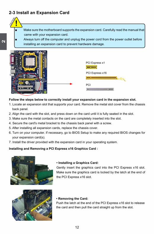
2-3 Install an expansion Card
follow the steps below to correctly install your expansion card in the expansion slot.1. Locate an expansion slot that supports your card. Remove the metal slot cover from the chassis
back panel.2. Align the card with the slot, and press down on the card until it is fully seated in the slot.3. Make sure the metal contacts on the card are completely inserted into the slot.4. Secure the card's metal bracket to the chassis back panel with a screw.5. After installing all expansion cards, replace the chassis cover.6. Turn on your computer. If necessary, go to BIOS Setup to make any required BIOS changes for
your expansion card(s).7. Install the driver provided with the expansion card in your operating system.
Installing and Removing a PCI Express x16 Graphics Card :
• Installing a Graphics Card:Gently insert the graphics card into the PCI Express x16 slot. Make sure the graphics card is locked by the latch at the end of the PCI Express x16 slot.
• Removing the Card:Push the latch at the end of the PCI Express x16 slot to release the card and then pull the card straight up from the slot.
PCI
PCI Express x1
PCI Express x16
■ Make sure the motherboard supports the expansion card. Carefully read the manual that came with your expansion card.
■ Always turn off the computer and unplug the power cord from the power outlet before installing an expansion card to prevent hardware damage.
CAUT
ION
!
2
13
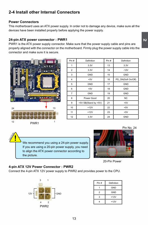
2-4 Install other Internal Connectors
Power ConnectorsThis motherboard uses an ATX power supply. In order not to damage any device, make sure all the devices have been installed properly before applying the power supply.
24-pin ATX power connector : PWR1PWR1 is the ATX power supply connector. Make sure that the power supply cable and pins areproperly aligned with the connector on the motherboard. Firmly plug the power supply cable into the connector and make sure it is secure.
4-pin ATX 12V Power Connector : PWR2Connect the 4-pin ATX 12V power supply to PWR2 and provides power to the CPU.
We recommend you using a 24-pin power supply. If you are using a 20-pin power supply, you need to align the ATX power connector according to the picture.
CAUT
ION
!
20-Pin Power
Pin No. 24
Pin # Definition
1 GND
2 GND
3 +12V
4 +12V
3 1
GND+12V
4 2
PWR2
Pin # Definition Pin # Definition
1 3.3V 13 3.3V
2 3.3V 14 -12V
3 GND 15 GND
4 +5V 16 PS_ON(Soft On/Off)
5 GND 17 GND
6 +5V 18 GND
7 GND 19 GND
8 Power Good 20 NC
9 +5V SB(Stand by +5V) 21 +5V
10 +12V 22 +5V
11 +12V 23 +5V
12 3.3V 24 GND
PWR1
24 13
12 1
2
14
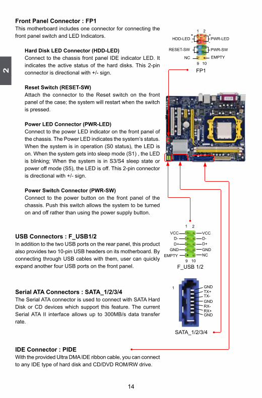
front Panel Connector : fP1This motherboard includes one connector for connecting the front panel switch and LED Indicators.
Hard Disk leD Connector (HDD-leD)Connect to the chassis front panel IDE indicator LED. It indicates the active status of the hard disks. This 2-pin connector is directional with +/- sign.
Reset Switch (ReSeT-SW)Attach the connector to the Reset switch on the front panel of the case; the system will restart when the switch is pressed.
Power leD Connector (PWR-leD)Connect to the power LED indicator on the front panel of the chassis. The Power LED indicates the system’s status. When the system is in operation (S0 status), the LED is on. When the system gets into sleep mode (S1) , the LED is blinking; When the system is in S3/S4 sleep state or power off mode (S5), the LED is off. This 2-pin connector is directional with +/- sign.
Power Switch Connector (PWR-SW)Connect to the power button on the front panel of the chassis. Push this switch allows the system to be turned on and off rather than using the power supply button.
USb Connectors : f_USb1/2In addition to the two USB ports on the rear panel, this product also provides two 10-pin USB headers on its motherboard. By connecting through USB cables with them, user can quickly expand another four USB ports on the front panel.
Serial ATA Connectors : SATA_1/2/3/4The Serial ATA connector is used to connect with SATA Hard Disk or CD devices which support this feature. The current Serial ATA II interface allows up to 300MB/s data transfer rate.
IDe Connector : PIDeWith the provided Ultra DMA IDE ribbon cable, you can connect to any IDE type of hard disk and CD/DVD ROM/RW drive.
HDD-LED
RESET-SW
NC
+-
PWR-SW
+
-PWR-LED
EMPTY
1 2
109
FP1
NCGND
VCC
D+D-
D+GND
D-VCC
EMPTY
1 2
109F_USB 1/2
SATA_1/2/3/4
GNDTX+TX-GNDRX-RX+GND
1
2
15
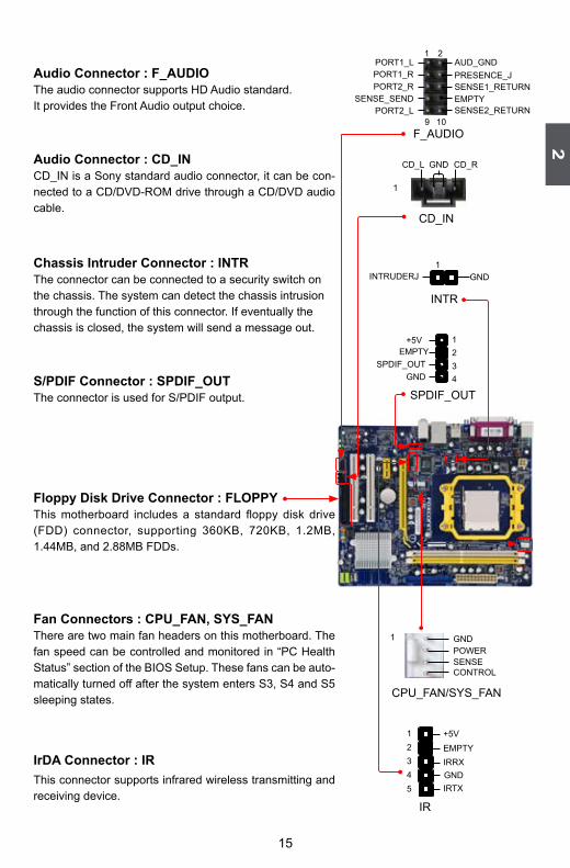
Audio Connector : f_AUDIoThe audio connector supports HD Audio standard. It provides the Front Audio output choice.
Audio Connector : CD_INCD_IN is a Sony standard audio connector, it can be con-nected to a CD/DVD-ROM drive through a CD/DVD audio cable.
Chassis Intruder Connector : INTRThe connector can be connected to a security switch on the chassis. The system can detect the chassis intrusion through the function of this connector. If eventually the chassis is closed, the system will send a message out.
S/PDIf Connector : SPDIf_oUTThe connector is used for S/PDIF output.
Floppy Disk Drive Connector : FLOPPYThis motherboard includes a standard floppy disk drive (FDD) connector, supporting 360KB, 720KB, 1.2MB, 1.44MB, and 2.88MB FDDs.
Fan Connectors : CPU_FAN, SYS_FANThere are two main fan headers on this motherboard. The fan speed can be controlled and monitored in “PC Health Status” section of the BIOS Setup. These fans can be auto-matically turned off after the system enters S3, S4 and S5 sleeping states.
IrDA Connector : IR This connector supports infrared wireless transmitting and receiving device.
INTR
GNDINTRUDERJ1
PORT1_LPORT1_R
PORT2_LSENSE_SEND
SENSE1_RETURNPRESENCE_J
EMPTYSENSE2_RETURN
AUD_GND1 2
109F_AUDIO
PORT2_R
1
CD_IN
CD_L GND CD_R
1
CPU_FAN/SYS_FAN
GNDPOWERSENSECONTROL
SPDIF_OUT
+5VEMPTY
SPDIF_OUTGND
1234
12345
+5VEMPTYIRRXGNDIRTX
IR
2
16
2-5 Jumpers
For some features needed, users can change the jumper settings on this motherboard to modify them. This section explains how to use the various functions of this motherboard by changing the jumper settings. Users should read the following content carefully prior to modifying any jumper setting.
Description of Jumpers1. For any jumper on this motherboard, pin 1 can be identified by the bold silkscreen next to it.
However, in this manual, pin 1 is simply labeled as “1”.2. The following table explains different types of the jumper settings. "Closed" means placing a jumper
cap on the two pins to temporarily short them. The shorting can also be done by touching two pins by a screwdriver for a few seconds, but using jumper cap is recommended. It can prevent hazardous ESD (Electrical Static Discharge) problem.
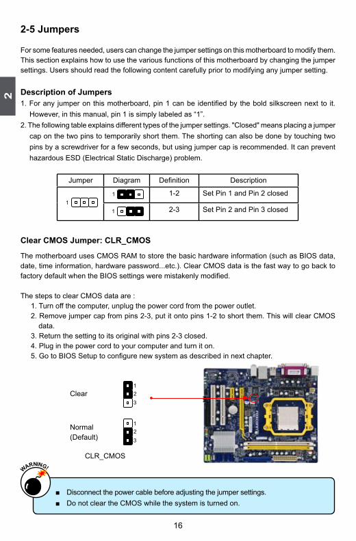
Clear CMoS Jumper: ClR_CMoS
The motherboard uses CMOS RAM to store the basic hardware information (such as BIOS data, date, time information, hardware password...etc.). Clear CMOS data is the fast way to go back to factory default when the BIOS settings were mistakenly modified.
The steps to clear CMOS data are : 1. Turn off the computer, unplug the power cord from the power outlet.2. Remove jumper cap from pins 2-3, put it onto pins 1-2 to short them. This will clear CMOS
data.3. Return the setting to its original with pins 2-3 closed.4. Plug in the power cord to your computer and turn it on.5. Go to BIOS Setup to configure new system as described in next chapter.
Jumper Diagram Definition Description
1-2 Set Pin 1 and Pin 2 closed
2-3 Set Pin 2 and Pin 3 closed1
1
1
Clear123
Normal(Default)
123
CLR_CMOS
■ Disconnect the power cable before adjusting the jumper settings. ■ Do not clear the CMOS while the system is turned on.
WARNING!
2
17
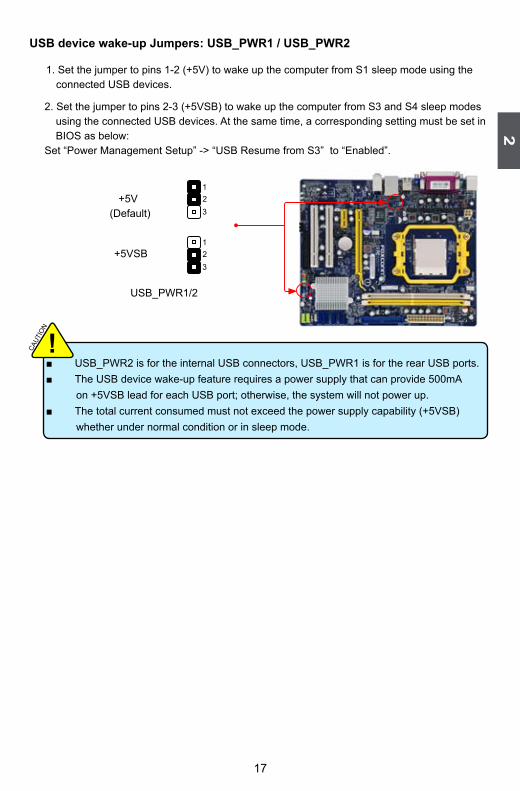
USB device wake-up Jumpers: USB_PWR1 / USB_PWR2
1. Set the jumper to pins 1-2 (+5V) to wake up the computer from S1 sleep mode using the connected USB devices.
2. Set the jumper to pins 2-3 (+5VSB) to wake up the computer from S3 and S4 sleep modes using the connected USB devices. At the same time, a corresponding setting must be set in BIOS as below:
Set “Power Management Setup” -> “USB Resume from S3” to “Enabled”.
USB_PWR1/2
+5V(Default)
123
+5VSB123
■ USB_PWR2 is for the internal USB connectors, USB_PWR1 is for the rear USB ports.■ The USB device wake-up feature requires a power supply that can provide 500mA
on +5VSB lead for each USB port; otherwise, the system will not power up.■ The total current consumed must not exceed the power supply capability (+5VSB)
whether under normal condition or in sleep mode.
CAUT
ION
!
This chapter tells how to change system settings through the BIOS Setup menus. Detailed descriptions of the BIOS parameters are also provided.You have to run the Setup Program when the following cases occur :1. An error message appears on the screen during the system
Power On Self Test (POST) process.2. You want to change the default CMOS settings.
This chapter includes the following information :■ Enter BIOS Setup■ Main Menu■ System Information■ Fox Central Control Unit■ Advanced BIOS Features■ Advanced Chipset Features ■ Integrated Peripherals■ Power Management Setup■ PC Health Status■ Load Optimized Defaults■ Set Supervisor Password■ Set User Password■ Save & Exit Setup■ Exit Without Saving
Since BIOS could be updated some other times, the BIOS information described in this manual is for reference only. We do not guarantee the content of this manual will remain consistent with the newly released BIOS at any given time in the future. Please visit our website for updated manual if it is available.
3
19
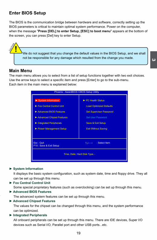
enter bIoS Setup
The BIOS is the communication bridge between hardware and software, correctly setting up the BIOS parameters is critical to maintain optimal system performance. Power on the computer, when the message "Press [Del] to enter Setup, [eSC] to boot menu" appears at the bottom of the screen, you can press [Del] key to enter Setup.
Main MenuThe main menu allows you to select from a list of setup functions together with two exit choices. Use the arrow keys to select a specific item and press [Enter] to go to the sub-menu.Each item in the main menu is explained below:
► System InformationIt displays the basic system configuration, such as system date, time and floppy drive. They all can be set up through this menu.
► Fox Central Control UnitSome special proprietary features (such as overclocking) can be set up through this menu.
► Advanced BIOS FeaturesThe advanced system features can be set up through this menu.
► Advanced Chipset FeaturesThe values for the chipset can be changed through this menu, and the system performance can be optimized.
► Integrated PeripheralsAll onboard peripherals can be set up through this menu. There are IDE devices, Super I/O devices such as Serial I/O, Parallel port and other USB ports...etc.
We do not suggest that you change the default values in the BIOS Setup, and we shall not be responsible for any damage which resulted from the change you made.
CAUT
ION
!
Phoenix - AwardBIOS CMOS Setup Utility
► System Information ► PC Health Status
► Fox Central Control Unit Load Optimized Defaults
► Advanced BIOS Features Set Supervisor Password
► Advanced Chipset Features Set User Password
► Integrated Peripherals Save & Exit Setup
► Power Management Setup Exit Without Saving
Esc : Quit ↑↓←→ : Select Item F10 : Save & Exit Setup
Time, Date, Hard Disk Type...
► System Information
3
20
► Power Management SetupAll the items related with Green function features can be set up through this menu.
► PC Health StatusThis setup enables you to read/change Fan speeds, and displays temperatures and voltages of your CPU/System.
► Load Optimized DefaultsThe optimal performance settings can be loaded through this menu. However, it may offer better performance in some ways (such as less I/O cards, less memory ...etc.), still, it may cause problem if you have more memory or I/O cards installed. It means, if your system loading is heavy, set to optimal default may sometimes come out an unstable system. What you need now is to adjust BIOS setting one by one, trial and error, to find out the best setting for your current system.
► Set Supervisor PasswordThe supervisor password can be set up through this menu.
► Set User PasswordThe user password can be set up through this menu.
► Save & Exit SetupSave setting values to CMOS and exit.
► Exit Without SavingDo not change anything and exit the setup.
When we talk about [+] and [-] keys in this manual, they are the single-keypad keys of the numeric keypad which is located at the right hand side of your desktop keyboard. They are not the combination keys made by pressing and holding down [Shift] key first, then press [+ =] or [ _-] key the next.
CAUT
ION
!
3
21
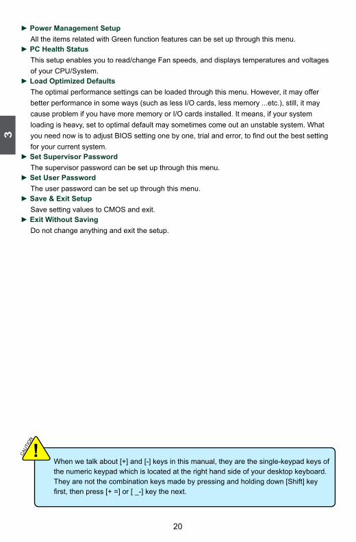
System Information
This submenu is used to set up the standard BIOS features, such as the date, time, floppy drive and so on. Use the arrow up/down keys to select an item, then use the [+] or [-] keys to change the setting.► Date - <weekday><month><date><year> format
Day—weekday from Sun. to Sat., automatically displayed by BIOS (Read Only).Month—month from 1 to 12.Date—date from 1st to 31st.Year—year, set up by users.Use [Enter], [Tab] keys to select a field. Use [+], [-], [PageUp] or [PageDown] to select a value.
► Time - <hour> : <minute> : <second> formatThis item allows you to configure the desired time. Use [Enter], [Tab] to move forward and select a field. Directly input a value or use [PageUp], [PageDown], [+] or [-] to select a value.
► IDE Channel Master / SlaveThese categories identify the hard disks connected to the PATA port in the system. In each channel’s display, you can press [Enter] to go to its submenu. You can further configure specific drive settings. [None] and [Auto] settings allow you to enable or disable this drive. [None] means no HDD is installed or set, and [Auto] means the system can auto-detect the hard disk when booting up. In Access Mode setting, selections of [CHS], [LBA], [Large] and [Auto] can help you to select hard drive for legacy compatibility. Award (Phoenix) BIOS can support 3 HDD modes: CHS, LBA and Large.
Note: Set to [Auto] , the system can detect the hard disk and select the HDD mode automatically. Suggest you select this option.
CHS For HDD <528MB
LBA For HDD >528MB & Supporting LBA (Logical Block Addressing)
Large For HDD >528MB but not supporting LBA
Phoenix - AwardBIOS CMOS Setup UtilitySystem Information
Date (mm:dd:yy) Fri, Feb 29 2008 Item Help Time (hh:mm:ss) 17 : 44 : 13 Menu Level ► ► IDE Channel Master [ None ] ► IDE Channel Slave [ None ] Change the day, month, ► SATA Channel 1 Master [ None ] year and century ► SATA Channel 2 Master [ None ] ► SATA Channel 3 Master [ None ] ► SATA Channel 4 Master [ None ] Drive A [1.44M, 3.5 in.] Halt On [All , But Keyboard] Model Name M61PMV BIOS Version B10 Memory 1024M MAC Address 04 4B 80 80 80 03 AMD Athlon(tm) 64 X2 Dual Core Processor 5200+
↑↓→←:Move Enter:Select +/-/PU/PD:Value F10:Save ESC:Exit F1:General Help F5: Previous Values F7: Optimized Defaults
Feb
3
22
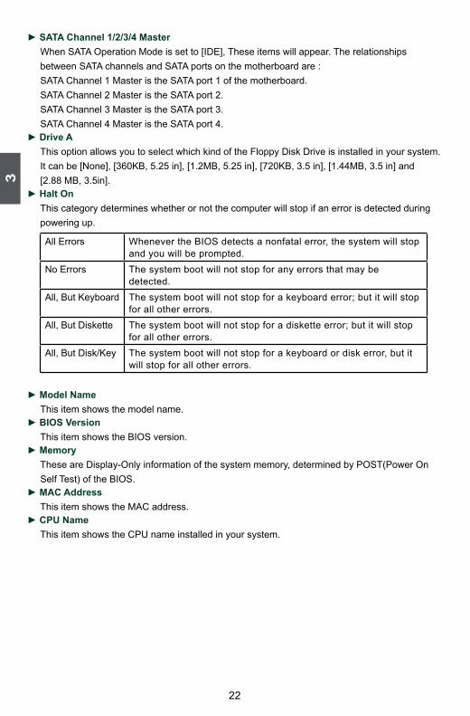
► SATA Channel 1/2/3/4 MasterWhen SATA Operation Mode is set to [IDE], These items will appear. The relationships between SATA channels and SATA ports on the motherboard are :SATA Channel 1 Master is the SATA port 1 of the motherboard.SATA Channel 2 Master is the SATA port 2.SATA Channel 3 Master is the SATA port 3.SATA Channel 4 Master is the SATA port 4.
► Drive AThis option allows you to select which kind of the Floppy Disk Drive is installed in your system. It can be [None], [360KB, 5.25 in], [1.2MB, 5.25 in], [720KB, 3.5 in], [1.44MB, 3.5 in] and [2.88 MB, 3.5in].
► Halt OnThis category determines whether or not the computer will stop if an error is detected during powering up.
► Model NameThis item shows the model name.
► BIOS VersionThis item shows the BIOS version.
► MemoryThese are Display-Only information of the system memory, determined by POST(Power On Self Test) of the BIOS.
► MAC AddressThis item shows the MAC address.
► CPU NameThis item shows the CPU name installed in your system.
All Errors Whenever the BIOS detects a nonfatal error, the system will stop and you will be prompted.
No Errors The system boot will not stop for any errors that may be detected.
All, But Keyboard The system boot will not stop for a keyboard error; but it will stop for all other errors.
All, But Diskette The system boot will not stop for a diskette error; but it will stop for all other errors.
All, But Disk/Key The system boot will not stop for a keyboard or disk error, but it will stop for all other errors.
3
23
fox Central Control Unit
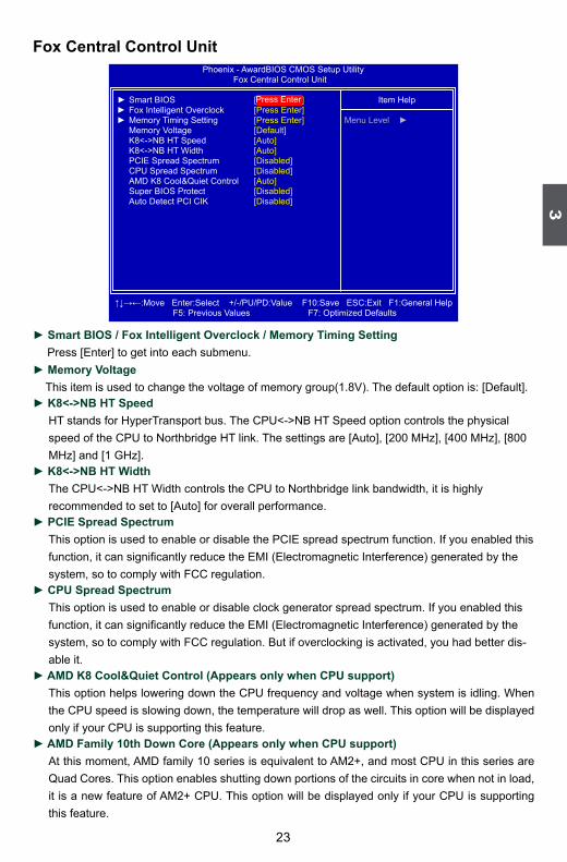
► Smart BIOS / Fox Intelligent Overclock / Memory Timing Setting Press [Enter] to get into each submenu.► Memory Voltage This item is used to change the voltage of memory group(1.8V). The default option is: [Default].► K8<->NB HT Speed
HT stands for HyperTransport bus. The CPU<->NB HT Speed option controls the physicalspeed of the CPU to Northbridge HT link. The settings are [Auto], [200 MHz], [400 MHz], [800 MHz] and [1 GHz].
► K8<->NB HT WidthThe CPU<->NB HT Width controls the CPU to Northbridge link bandwidth, it is highlyrecommended to set to [Auto] for overall performance.
► PCIE Spread SpectrumThis option is used to enable or disable the PCIE spread spectrum function. If you enabled this function, it can significantly reduce the EMI (Electromagnetic Interference) generated by the system, so to comply with FCC regulation.
► CPU Spread SpectrumThis option is used to enable or disable clock generator spread spectrum. If you enabled this function, it can significantly reduce the EMI (Electromagnetic Interference) generated by the system, so to comply with FCC regulation. But if overclocking is activated, you had better dis-able it.
► AMD K8 Cool&Quiet Control (Appears only when CPU support)This option helps lowering down the CPU frequency and voltage when system is idling. When the CPU speed is slowing down, the temperature will drop as well. This option will be displayed only if your CPU is supporting this feature.
► AMD Family 10th Down Core (Appears only when CPU support)At this moment, AMD family 10 series is equivalent to AM2+, and most CPU in this series are Quad Cores. This option enables shutting down portions of the circuits in core when not in load, it is a new feature of AM2+ CPU. This option will be displayed only if your CPU is supporting this feature.
Phoenix - AwardBIOS CMOS Setup Utility Fox Central Control Unit
► Smart BIOS [Press Enter] Item Help ► Fox Intelligent Overclock [Press Enter] ► Memory Timing Setting [Press Enter] Menu Level ► Memory Voltage [Default] K8<->NB HT Speed [Auto] K8<->NB HT Width [Auto] PCIE Spread Spectrum [Disabled] CPU Spread Spectrum [Disabled] AMD K8 Cool&Quiet Control [Auto] Super BIOS Protect [Disabled] Auto Detect PCI CIK [Disabled]
↑↓→←:Move Enter:Select +/-/PU/PD:Value F10:Save ESC:Exit F1:General Help F5: Previous Values F7: Optimized Defaults
Press Enter
3
24
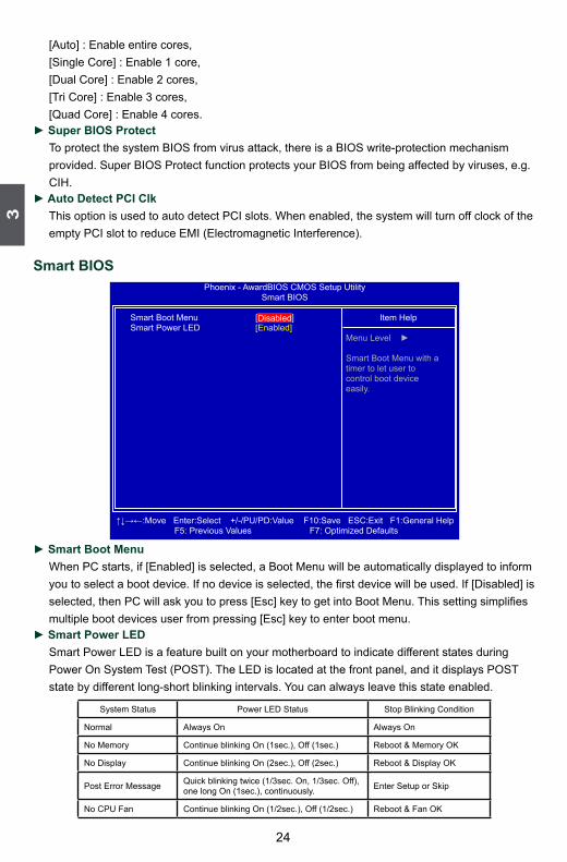
[Auto] : Enable entire cores,[Single Core] : Enable 1 core,[Dual Core] : Enable 2 cores,[Tri Core] : Enable 3 cores,[Quad Core] : Enable 4 cores.
► Super BIOS ProtectTo protect the system BIOS from virus attack, there is a BIOS write-protection mechanism provided. Super BIOS Protect function protects your BIOS from being affected by viruses, e.g. CIH.
► Auto Detect PCI ClkThis option is used to auto detect PCI slots. When enabled, the system will turn off clock of the empty PCI slot to reduce EMI (Electromagnetic Interference).
Smart bIoS
► Smart Boot MenuWhen PC starts, if [Enabled] is selected, a Boot Menu will be automatically displayed to inform you to select a boot device. If no device is selected, the first device will be used. If [Disabled] is selected, then PC will ask you to press [Esc] key to get into Boot Menu. This setting simplifies multiple boot devices user from pressing [Esc] key to enter boot menu.
► Smart Power LEDSmart Power LED is a feature built on your motherboard to indicate different states during Power On System Test (POST). The LED is located at the front panel, and it displays POST state by different long-short blinking intervals. You can always leave this state enabled.
Phoenix - AwardBIOS CMOS Setup UtilitySmart BIOS
Smart Boot Menu [Disabled] Item Help Smart Power LED [Enabled] Menu Level ►
Smart Boot Menu with a timer to let user to control boot device easily.
↑↓→←:Move Enter:Select +/-/PU/PD:Value F10:Save ESC:Exit F1:General Help F5: Previous Values F7: Optimized Defaults
Disabled
System Status Power LED Status Stop Blinking Condition
Normal Always On Always On
No Memory Continue blinking On (1sec.), Off (1sec.) Reboot & Memory OK
No Display Continue blinking On (2sec.), Off (2sec.) Reboot & Display OK
Post Error Message Quick blinking twice (1/3sec. On, 1/3sec. Off), one long On (1sec.), continuously. Enter Setup or Skip
No CPU Fan Continue blinking On (1/2sec.), Off (1/2sec.) Reboot & Fan OK
3
25
Fox Intelligent Overclock
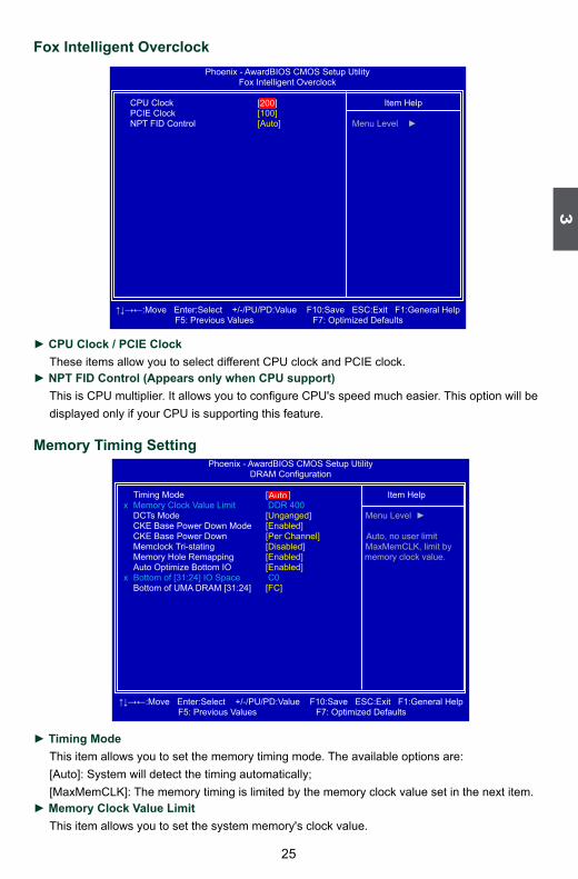
► CPU Clock / PCIE Clock These items allow you to select different CPU clock and PCIE clock.
► NPT FID Control (Appears only when CPU support)This is CPU multiplier. It allows you to configure CPU's speed much easier. This option will be displayed only if your CPU is supporting this feature.
Memory Timing Setting
► Timing ModeThis item allows you to set the memory timing mode. The available options are:[Auto]: System will detect the timing automatically;[MaxMemCLK]: The memory timing is limited by the memory clock value set in the next item.
► Memory Clock Value LimitThis item allows you to set the system memory's clock value.
Phoenix - AwardBIOS CMOS Setup UtilityDRAM Configuration
Timing Mode [A uto] Item Help x Memory Clock Value Limit DDR 400 DCTs Mode [Unganged] Menu Level ► CKE Base Power Down Mode [Enabled] CKE Base Power Down [Per Channel] Auto, no user limit Memclock Tri-stating [Disabled] MaxMemCLK, limit by Memory Hole Remapping [Enabled] memory clock value. Auto Optimize Bottom IO [Enabled] x Bottom of [31:24] IO Space C0 Bottom of UMA DRAM [31:24] [FC]
↑↓→←:Move Enter:Select +/-/PU/PD:Value F10:Save ESC:Exit F1:General Help F5: Previous Values F7: Optimized Defaults
Auto
Phoenix - AwardBIOS CMOS Setup UtilityFox Intelligent Overclock
CPU Clock [200] Item Help PCIE Clock [100] NPT FID Control [Auto] Menu Level ►
↑↓→←:Move Enter:Select +/-/PU/PD:Value F10:Save ESC:Exit F1:General Help F5: Previous Values F7: Optimized Defaults
200
3
26
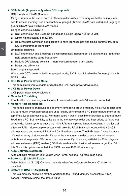
► DCTs Mode (Appears only when CPU support)DCT stands for DRAM Controller.Ganged refers to the use of both DRAM controllers within a memory controller acting in con-cert to access memory. For a description of ganged (128-bit DRAM data width) and unganged (64-bit DRAM data width) DRAM modes :Ganged channels (DDR2) :■ DCT channels A and B can be ganged as a single logical 128-bit DIMM.■ Offers highest DDR2 bandwidth.■ Requires both DIMMs in a logical pair to have identical size and timing parameters, both
DCTs programmed identically.Unganged channels■ DCT channels A and B operate as two completely independent 64-bit channels (both chan-
nels operate at the same frequency).■ Reduce DRAM page conflicts – more concurrent open dram pages .■ Better bus efficiency.Burst lengths supportedWhen both DCTs are enabled in unganged mode, BIOS must initialize the frequency of each DCT in order.
► CKE Base Power Down ModeThis item allows you to enable or disable the CKE base power down mode.
► CKE Base Power DownCKE power down mode selection.
► Memclock Tri-statingEnables the DDR memory clocks to be tristated when alternate VID mode is enabled.
► Memory Hole RemappingThis item is used to enable/disable memory remapping around memory hole. PCI doesn't actu-ally care much which addresses are used, but by convention the PC platform puts them at the top of the 32-bit address space. For many years it wasn't possible or practical to put that much RAM into a PC. But now it is, so it's up to the memory controller and host bridge to figure out what to do. Many systems cause that high RAM to simply be ignored, resulting in the loss of effective RAM. More complex systems will take the RAM that would occupy that 3.5-4GB address space and re-map it into the 4.0-4.5 address space. The RAM doesn't care because it's just an array of storage cells, it's up to the memory controller to associate addresses with those storage cells. Of course, that only works if you're using a 64-bit (or 32-bit physical address extension (PAE) enabled) OS that can deal with physical addresses larger than 32 bits.Once this option is enabled, the BIOS can see 4096MB of memory.
► Auto Optimize Bottom IOAuto optimize maximum DRAM size when kernel assigns PCI resources done.
► Bottom of [31:24] IO SpaceSelect bottom of [31:24] IO space manually when "Auto Optimize Bottom IO" option is disabled.
► Bottom of UMA DRAM [31:24]This is a memory allocation method addition to the Unified Memory Architecture (UMA) concept. Normally, select the default value.
3
27
Advanced BIOS Features
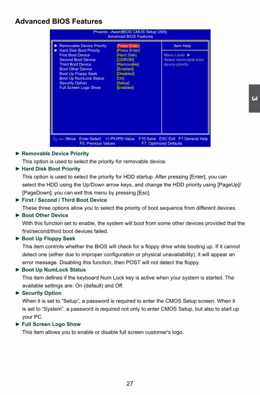
► Removable Device PriorityThis option is used to select the priority for removable device.
► Hard Disk Boot PriorityThis option is used to select the priority for HDD startup. After pressing [Enter], you can select the HDD using the Up/Down arrow keys, and change the HDD priority using [PageUp]/[PageDown]; you can exit this menu by pressing [Esc].
► First / Second / Third Boot DeviceThese three options allow you to select the priority of boot sequence from different devices.
► Boot Other DeviceWith this function set to enable, the system will boot from some other devices provided that the first/second/third boot devices failed.
► Boot Up Floppy SeekThis item controls whether the BIOS will check for a floppy drive while booting up. If it cannot detect one (either due to improper configuration or physical unavailability), it will appear an error message. Disabling this function, then POST will not detect the floppy.
► Boot Up NumLock StatusThis item defines if the keyboard Num Lock key is active when your system is started. The available settings are: On (default) and Off.
► Security OptionWhen it is set to “Setup”, a password is required to enter the CMOS Setup screen. When it is set to “System”, a password is required not only to enter CMOS Setup, but also to start up your PC.
► Full Screen Logo ShowThis item allows you to enable or disable full screen customer's logo.
Phoenix - AwardBIOS CMOS Setup UtilityAdvanced BIOS Features
► Removable Device Priority [Press Enter] Item Help ► Hard Disk Boot Priority [Press Enter] First Boot Device [Hard Disk] Menu Level ► Second Boot Device [CDROM] Select removable boot Third Boot Device [Removable] device priority Boot Other Device [Enabled] Boot Up Floppy Seek [Disabled] Boot Up NumLock Status [On] Security Option [Setup] Full Screen Logo Show [Enabled]
↑↓→←:Move Enter:Select +/-/PU/PD:Value F10:Save ESC:Exit F1:General Help F5: Previous Values F7: Optimized Defaults
Press Enter
3
28
Advanced Chipset Features
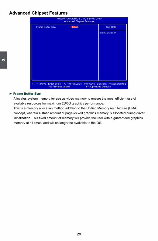
► Frame Buffer SizeAllocates system memory for use as video memory to ensure the most efficient use of available resources for maximum 2D/3D graphics performance.This is a memory allocation method addition to the Unified Memory Architecture (UMA) concept, wherein a static amount of page-locked graphics memory is allocated during driver initialization. This fixed amount of memory will provide the user with a guaranteed graphics memory at all times, and will no longer be available to the OS.
Phoenix - AwardBIOS CMOS Setup UtilityAdvanced Chipset Features
Frame Buffer Size [128M] Item Help Menu Level ►
↑↓→←:Move Enter:Select +/-/PU/PD:Value F10:Save ESC:Exit F1:General Help F5: Previous Values F7: Optimized Defaults
128M
3
29
Integrated Peripherals
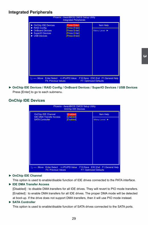
► OnChip IDE Devices / RAID Config / OnBoard Devices / SuperIO Devices / USB DevicesPress [Enter] to go to each submenu.
OnChip IDE Devices
► OnChip IDE ChannelThis option is used to enable/disable function of IDE drives connected to the PATA interface.
► IDE DMA Transfer Access[Disabled] : to disable DMA transfers for all IDE drives. They will revert to PIO mode transfers. [Enabled] : to enable DMA transfers for all IDE drives. The proper DMA mode will be detected at boot-up. If the drive does not support DMA transfers, then it will use PIO mode instead.
► SATA ControllerThis option is used to enable/disable function of SATA drives connected to the SATA ports.
Phoenix - AwardBIOS CMOS Setup UtilityIntegrated Peripherals
► OnChip IDE Devices [Press Enter] Item Help ► RAID Config [Press Enter] ► OnBoard Devices [Press Enter] Menu Level ► ► SuperIO Devices [Press Enter] ► USB Devices [Press Enter]
↑↓→←:Move Enter:Select +/-/PU/PD:Value F10:Save ESC:Exit F1:General Help F5: Previous Values F7: Optimized Defaults
Press Enter
Phoenix - AwardBIOS CMOS Setup UtilityOnChip IDE Devices
OnChip IDE Channel [Enabled] Item Help IDE DMA Transfer Access [Enabled] SATA Controller [Enabled] Menu Level ►
↑↓→←:Move Enter:Select +/-/PU/PD:Value F10:Save ESC:Exit F1:General Help F5: Previous Values F7: Optimized Defaults
Enabled
3
30
RAID Config
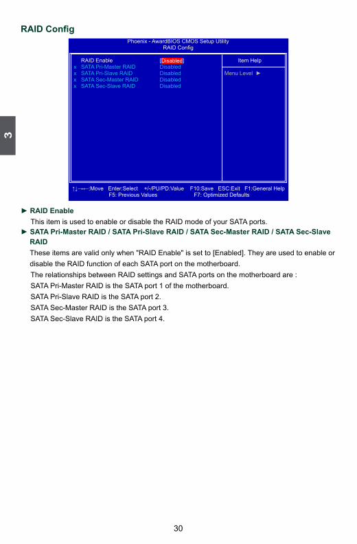
► RAID EnableThis item is used to enable or disable the RAID mode of your SATA ports.
► SATA Pri-Master RAID / SATA Pri-Slave RAID / SATA Sec-Master RAID / SATA Sec-Slave RAID
These items are valid only when "RAID Enable" is set to [Enabled]. They are used to enable or disable the RAID function of each SATA port on the motherboard.The relationships between RAID settings and SATA ports on the motherboard are :SATA Pri-Master RAID is the SATA port 1 of the motherboard.SATA Pri-Slave RAID is the SATA port 2.SATA Sec-Master RAID is the SATA port 3.SATA Sec-Slave RAID is the SATA port 4.
Phoenix - AwardBIOS CMOS Setup UtilityRAID Config
RAID Enable [ IDE] Item Help x SATA Pri-Master RAID Disabled x SATA Pri-Slave RAID Disabled Menu Level ► x SATA Sec-Master RAID Disabled x SATA Sec-Slave RAID Disabled
↑↓→←:Move Enter:Select +/-/PU/PD:Value F10:Save ESC:Exit F1:General Help F5: Previous Values F7: Optimized Defaults
Disabled
3
31
OnBoard Devices
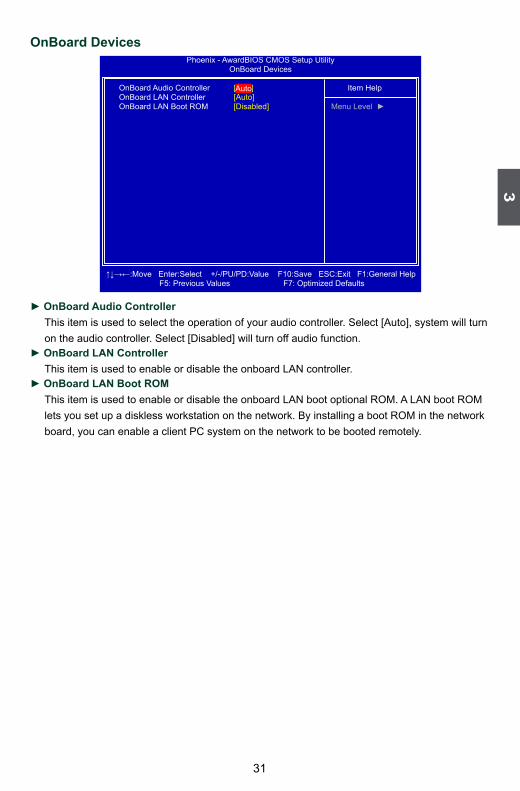
► OnBoard Audio ControllerThis item is used to select the operation of your audio controller. Select [Auto], system will turn on the audio controller. Select [Disabled] will turn off audio function.
► OnBoard LAN ControllerThis item is used to enable or disable the onboard LAN controller.
► OnBoard LAN Boot ROMThis item is used to enable or disable the onboard LAN boot optional ROM. A LAN boot ROM lets you set up a diskless workstation on the network. By installing a boot ROM in the network board, you can enable a client PC system on the network to be booted remotely.
Phoenix - AwardBIOS CMOS Setup UtilityOnBoard Devices
OnBoard Audio Controller [ ] Item Help OnBoard LAN Controller [Auto] OnBoard LAN Boot ROM [Disabled] Menu Level ►
↑↓→←:Move Enter:Select +/-/PU/PD:Value F10:Save ESC:Exit F1:General Help F5: Previous Values F7: Optimized Defaults
Auto
3
32
SuperIO Devices
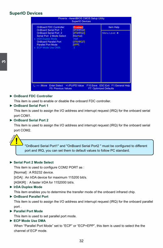
► OnBoard FDC ControllerThis item is used to enable or disable the onboard FDC controller.
► OnBoard Serial Port 1This item is used to assign the I/O address and interrupt request (IRQ) for the onboard serial port COM1.
► OnBoard Serial Port 2This item is used to assign the I/O address and interrupt request (IRQ) for the onboard serial port COM2.
► Serial Port 2 Mode SelectThis item is used to configure COM2 PORT as :[Normal] : A RS232 device. [IrDA] : An IrDA device for maximum 115200 bit/s.[ASKIR] : A faster IrDA for 1152000 bit/s.
► IrDA Duplex ModeThis item enables you to determine the transfer mode of the onboard infrared chip.
► OnBoard Parallel Port This item is used to assign the I/O address and interrupt request (IRQ) for the onboard parallel port .
► Parallel Port Mode This item is used to set parallel port mode.
► ECP Mode Use DMA When “Parallel Port Mode” set to “ECP” or “ECP+EPP”, this item is used to select the the channel of ECP mode.
Phoenix - AwardBIOS CMOS Setup UtilitySuperIO Devices
OnBoard FDC Controller [Enabled] Item Help OnBoard Serial Port 1 [3F8/IRQ4] OnBoard Serial Port 2 [2F8/IRQ3] Menu Level ► Serial Port 2 Mode Select [Normal] x IrDA Duplex Mode Half OnBoard Parallel Port [378/IRQ7] Parallel Port Mode [SPP] x ECP Mode Use DMA 3
↑↓→←:Move Enter:Select +/-/PU/PD:Value F10:Save ESC:Exit F1:General Help F5: Previous Values F7: Optimized Defaults
Enabled
"OnBoard Serial Port1" and "OnBoard Serial Port2 " must be configured to different port and IRQ, you can set them to default values to follow PC standard.
CAUT
ION
!
3
33
USB Devices
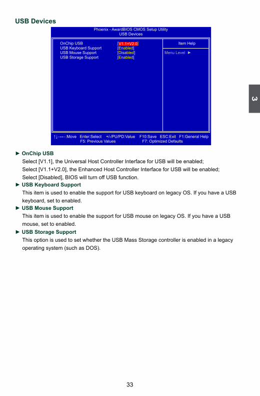
► OnChip USBSelect [V1.1], the Universal Host Controller Interface for USB will be enabled;Select [V1.1+V2.0], the Enhanced Host Controller Interface for USB will be enabled; Select [Disabled], BIOS will turn off USB function.
► USB Keyboard SupportThis item is used to enable the support for USB keyboard on legacy OS. If you have a USB keyboard, set to enabled.
► USB Mouse SupportThis item is used to enable the support for USB mouse on legacy OS. If you have a USB mouse, set to enabled.
► USB Storage SupportThis option is used to set whether the USB Mass Storage controller is enabled in a legacy operating system (such as DOS).
Phoenix - AwardBIOS CMOS Setup UtilityUSB Devices
OnChip USB [ ] Item Help USB Keyboard Support [Enabled] USB Mouse Support [Disabled] Menu Level ► USB Storage Support [Enabled]
↑↓→←:Move Enter:Select +/-/PU/PD:Value F10:Save ESC:Exit F1:General Help F5: Previous Values F7: Optimized Defaults
V1.1+V2.0
3
34
Power Management Setup
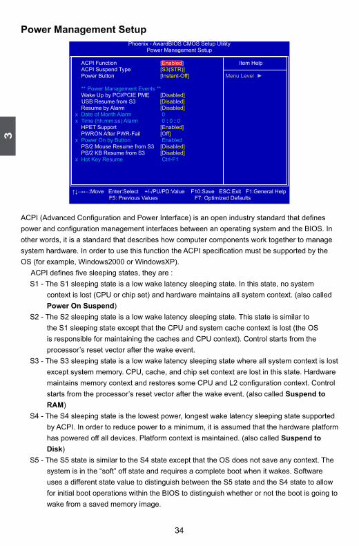
ACPI (Advanced Configuration and Power Interface) is an open industry standard that defines power and configuration management interfaces between an operating system and the BIOS. In other words, it is a standard that describes how computer components work together to manage system hardware. In order to use this function the ACPI specification must be supported by the OS (for example, Windows2000 or WindowsXP).
ACPI defines five sleeping states, they are :S1 - The S1 sleeping state is a low wake latency sleeping state. In this state, no system
context is lost (CPU or chip set) and hardware maintains all system context. (also called Power on Suspend)
S2 - The S2 sleeping state is a low wake latency sleeping state. This state is similar to the S1 sleeping state except that the CPU and system cache context is lost (the OS is responsible for maintaining the caches and CPU context). Control starts from the processor’s reset vector after the wake event.
S3 - The S3 sleeping state is a low wake latency sleeping state where all system context is lost except system memory. CPU, cache, and chip set context are lost in this state. Hardware maintains memory context and restores some CPU and L2 configuration context. Control starts from the processor’s reset vector after the wake event. (also called Suspend to RAM)
S4 - The S4 sleeping state is the lowest power, longest wake latency sleeping state supported by ACPI. In order to reduce power to a minimum, it is assumed that the hardware platform has powered off all devices. Platform context is maintained. (also called Suspend to Disk)
S5 - The S5 state is similar to the S4 state except that the OS does not save any context. The system is in the “soft” off state and requires a complete boot when it wakes. Software uses a different state value to distinguish between the S5 state and the S4 state to allow for initial boot operations within the BIOS to distinguish whether or not the boot is going to wake from a saved memory image.
Phoenix - AwardBIOS CMOS Setup UtilityPower Management Setup
ACPI Function [Enabled] Item Help ACPI Suspend Type [S3(STR)] Power Button [Instant-Off] Menu Level ►
** Power Management Events ** Wake Up by PCI/PCIE PME [Disabled] USB Resume from S3 [Disabled] Resume by Alarm [Disabled] x Date of Month Alarm 0 x Time (hh:mm:ss) Alarm 0 : 0 : 0 HPET Support [Enabled] PWRON After PWR-Fail [Off] x Power On by Button Enabled PS/2 Mouse Resume from S3 [Disabled] PS/2 KB Resume from S3 [Disabled] x Hot Key Resume Ctrl-F1
↑↓→←:Move Enter:Select +/-/PU/PD:Value F10:Save ESC:Exit F1:General Help F5: Previous Values F7: Optimized Defaults
Enabled

3
35
► ACPI FunctionThis item is used to enable or disable the ACPI function.
► ACPI Suspend TypeThis item is used to set the energy saving mode of the ACPI function. When you select “S1 (POS)” mode, the power is always on and computer can be resumed at any time. When you select “S3 (STR)” mode, the power will be down after a period of time. The status of the computer before it entering STR will be saved in memory, and the computer can quickly return to previous state when the STR function wakes.
► Power ButtonThis item is used to set the power down method. This function is only valid for systems using an ATX power supply. When set to [Delay 4 Sec.], the power button will put the system in Suspend mode if you push the power button in less than 4 Second then release. If set to [Instant-Off], the PC powers off immediately when the power button is pressed.
** Power Management Events **► Wake Up by PCI/PCIE PME This item is used to set the system to be waken up by PCI/PCIE card.► USB Resume from S3 This item is used to set the system to be waken up by USB device when it is staying at S3 (Suspend to RAM) state.► Resume by Alarm
This item is used to set the timing of the start-up function. In order to use this function, the start-up password function must be disabled. Also, the PC power source must not be turned off.
► Date of Month AlarmWhen "Resume by Alarm" is set to “Enabled”, this item can be modified. It is used to set the timing for the start-up date.
► Time (hh:mm:ss) AlarmWhen "Resume by Alarm" is set to “Enabled”, this item can be modified. It is used to set the timing for the start-up time.
► HPET SupportHPET stands for High Precision Even Timer. If you have the HPET disabled, then windows does not have access to it and therefore falls back to less accurate timing methods. This item is used to enable or disable the HPET Support.
► PWRON After PWR-FailThis item is used to set which state the PC will take with when it resumes after an AC power loss.
► Power On by ButtonThis feature is valid only when "PS/2 KB Resume from S3" is set to Hot key or Keyboard 98. Enabling this feature allows normal powering on by pressing power button, while disabling it then pressing power button has no function.
► PS/2 Mouse Resume from S3When enabled, it allows you to use the PS/2 mouse to wake up the system from S3 mode. This feature requires an ATX power supply.
► PS/2 Kb Resume from S3This item allows you to use the PS/2 keyboard to wake up the system from S3 mode. This feature requires an ATX power supply. The setting values: [Disabled]; [Hot KEY]; [Any KEY],

3
36
and [Keyboard 98].► Hot Key Resume
Wen "PS/2 KB Resume from S3" is set to [Hot KEY], this item allows you to press a [Ctrl] + Function key to wake up the system from S3 mode.
3
37
PC Health Status
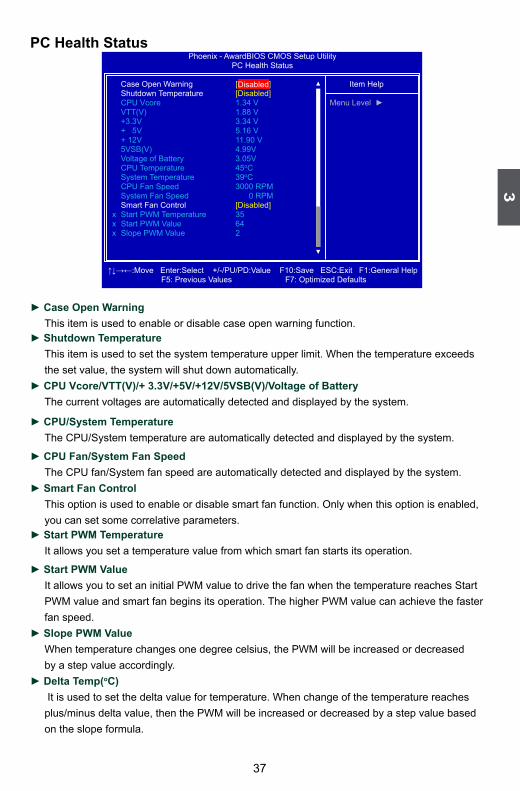
► Case Open WarningThis item is used to enable or disable case open warning function.
► Shutdown TemperatureThis item is used to set the system temperature upper limit. When the temperature exceeds the set value, the system will shut down automatically.
► CPU Vcore/VTT(V)/+ 3.3V/+5V/+12V/5VSB(V)/Voltage of BatteryThe current voltages are automatically detected and displayed by the system.
► CPU/System TemperatureThe CPU/System temperature are automatically detected and displayed by the system.
► CPU Fan/System Fan Speed The CPU fan/System fan speed are automatically detected and displayed by the system.
► Smart fan ControlThis option is used to enable or disable smart fan function. Only when this option is enabled, you can set some correlative parameters.
► Start PWM Temperature It allows you set a temperature value from which smart fan starts its operation.
► Start PWM Value It allows you to set an initial PWM value to drive the fan when the temperature reaches Start PWM value and smart fan begins its operation. The higher PWM value can achieve the faster fan speed.
► Slope PWM ValueWhen temperature changes one degree celsius, the PWM will be increased or decreasedby a step value accordingly.
► Delta Temp(oC) It is used to set the delta value for temperature. When change of the temperature reaches plus/minus delta value, then the PWM will be increased or decreased by a step value based on the slope formula.
Phoenix - AwardBIOS CMOS Setup UtilityPC Health Status
Case Open Warning [Disabled] Item Help Shutdown Temperature [Disabled] CPU Vcore 1.34 V Menu Level ► VTT(V) 1.88 V +3.3V 3.34 V + 5V 5.16 V + 12V 11.90 V 5VSB(V) 4.99V Voltage of Battery 3.05V CPU Temperature 45oC System Temperature 39oC CPU Fan Speed 3000 RPM System Fan Speed 0 RPM Smart Fan Control [Disabled] x Start PWM Temperature 35 x Start PWM Value 64 x Slope PWM Value 2
↑↓→←:Move Enter:Select +/-/PU/PD:Value F10:Save ESC:Exit F1:General Help F5: Previous Values F7: Optimized Defaults
Disabled
3
38
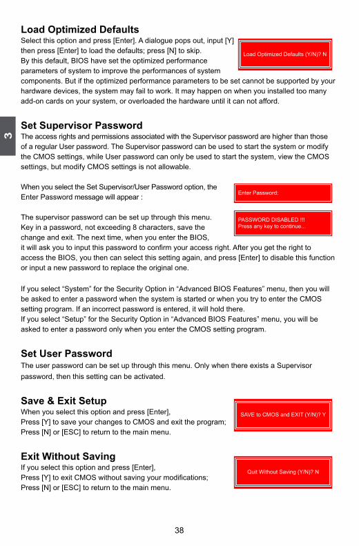
Load Optimized DefaultsSelect this option and press [Enter]. A dialogue pops out, input [Y] then press [Enter] to load the defaults; press [N] to skip. By this default, BIOS have set the optimized performance parameters of system to improve the performances of system components. But if the optimized performance parameters to be set cannot be supported by your hardware devices, the system may fail to work. It may happen on when you installed too many add-on cards on your system, or overloaded the hardware until it can not afford.
Set Supervisor PasswordThe access rights and permissions associated with the Supervisor password are higher than those of a regular User password. The Supervisor password can be used to start the system or modify the CMOS settings, while User password can only be used to start the system, view the CMOS settings, but modify CMOS settings is not allowable.
When you select the Set Supervisor/User Password option, the Enter Password message will appear :
The supervisor password can be set up through this menu.Key in a password, not exceeding 8 characters, save the change and exit. The next time, when you enter the BIOS, it will ask you to input this password to confirm your access right. After you get the right to access the BIOS, you then can select this setting again, and press [Enter] to disable this function or input a new password to replace the original one.
If you select “System” for the Security Option in “Advanced BIOS Features” menu, then you will be asked to enter a password when the system is started or when you try to enter the CMOS setting program. If an incorrect password is entered, it will hold there. If you select “Setup” for the Security Option in “Advanced BIOS Features” menu, you will be asked to enter a password only when you enter the CMOS setting program.
Set User PasswordThe user password can be set up through this menu. Only when there exists a Supervisor password, then this setting can be activated.
Save & Exit SetupWhen you select this option and press [Enter], Press [Y] to save your changes to CMOS and exit the program; Press [N] or [ESC] to return to the main menu.
Exit Without SavingIf you select this option and press [Enter], Press [Y] to exit CMOS without saving your modifications; Press [N] or [ESC] to return to the main menu.
Load Optimized Defaults (Y/N)? N
SAVE to CMOS and EXIT (Y/N)? Y
Quit Without Saving (Y/N)? N
Enter Password:
PASSWORD DISABLED !!! Press any key to continue...
The utility CD that came with the motherboard contains useful software and several utility drivers that enhance the motherboard features.
This chapter includes the following information:■ Utility CD content■ Install driver and utility■ FOX ONE■ FOX LiveUpdate■ FOX LOGO■ FOX DMI
Note : Because each module is independent, so the section number will be reorganized and unique to each module, please understand.
4
40
Utility CD contentThis motherboard comes with one DVD. You can simply put it into your DVD-ROM drive, and the main menu will be displayed on your PC screen to guide you how to install.
1. Install DriverUse these options to install all the drivers for your system. You should install the drivers in order, and you need to restart your computer after all the drivers have been installed.
M61PMV-E:A. NVIDIA MCP61 Chipset DriverB. Realtek HDA Audio DriverC. Realtek LAN Driver
M61PMV/ M61PMVK:A. NVIDIA MCP61 Chipset DriverB. VIA HDA Audio Driver
2. Software UtilitiesUse these options to install additional software programs. FOX ONE is a very powerful user interface program which allows you to change your system setting without going to BIOS. Some auto features help user to improve (or overclock) your system without being a computer literate.
A. FOX ONE B. FOX LiveUpdateC. FOX LOGOD. FOX DMIE. Microsoft DirectX 9.0F. Adobe Acrobat ReaderG. Norton Internet Security
4
41
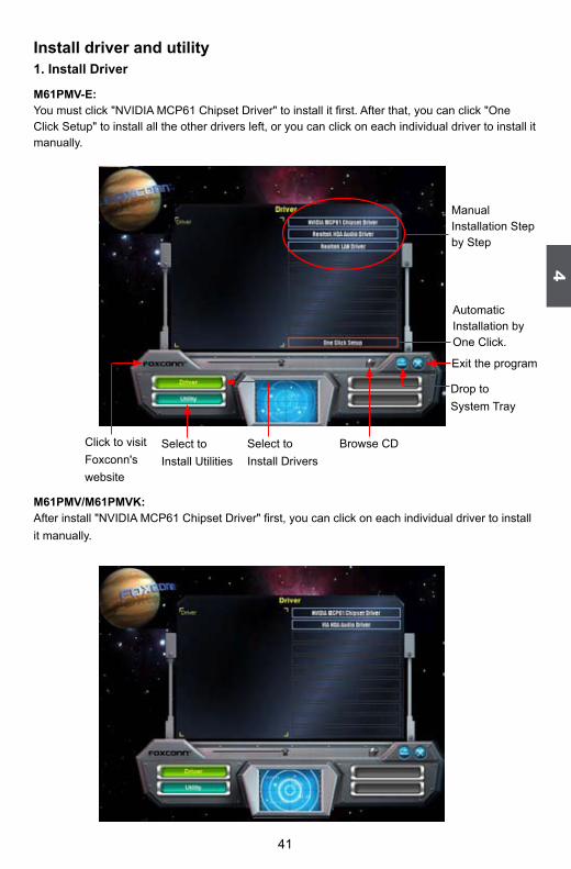
Install driver and utility1. Install Driver
M61PMV-e:You must click "NVIDIA MCP61 Chipset Driver" to install it first. After that, you can click "One Click Setup" to install all the other drivers left, or you can click on each individual driver to install it manually.
M61PMV/M61PMVK:After install "NVIDIA MCP61 Chipset Driver" first, you can click on each individual driver to install it manually.
Manual Installation Step by Step
Select to Install Utilities
Select to Install Drivers
Click to visit Foxconn's website
Browse CD
Exit the program
Drop to System Tray
Automatic Installation by One Click.
4
42
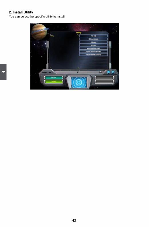
2. Install UtilityYou can select the specific utility to install.
4
43
foX oNeFOX ONE is a powerful utility for easily modifying system settings. It also allows users to monitor various temperature values, voltage values, frequencies and fan speeds at any time.
With FOX ONE, you can :■ Modify system performance settings, such as the CPU and memory bus speeds, CPU
voltages, fan speeds, and other system performance options.■ Monitor hardware temperatures, voltages, frequencies and fan speeds.
Supporting Operating Systems :■ Windows 2000 ■ Windows XP (32-bit and 64-bit)■ Windows 2003 (32-bit and 64-bit) ■ Windows Vista (32-bit and 64-bit)
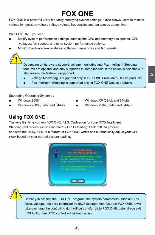
Using FOX ONE :The very first time you run FOX ONE, F.I.S. Calibration function (FOX IntelligentStepping) will require you to calibrate the CPU’s loading. Click “OK” to proceedand start the Utility. F.I.S. is a feature of FOX ONE, which can automatically adjust your CPU clock based on your current system loading.
Before you running the FOX ONE program, the system parameters (such as CPU clock, voltage...etc.) are controlled by BIOS settings. After you run FOX ONE, it will take over, and the controlling right will be transferred to FOX ONE. Later, if you exit FOX ONE, then BIOS control will be back again.
CAUT
ION
!
Depending on hardware support, voltage monitoring and Fox Intelligent Stepping features are optional and only supported in some models. If the option is selectable, it also means the feature is supported.■ Voltage Monitoring is supported only in FOX ONE Premium & Deluxe products.■ Fox Intelligent Stepping is supported only in FOX ONE Deluxe products.
CAUT
ION
!
4
44
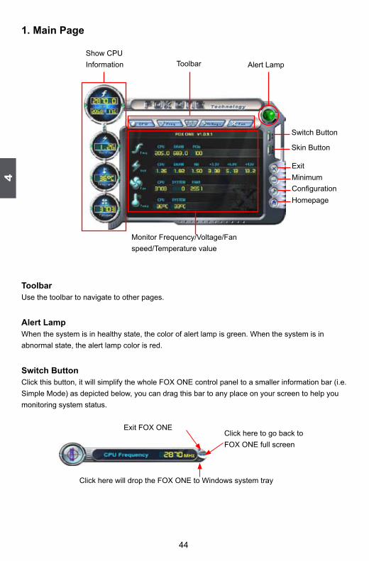
1. Main Page
ToolbarUse the toolbar to navigate to other pages.
Alert lampWhen the system is in healthy state, the color of alert lamp is green. When the system is in abnormal state, the alert lamp color is red.
Switch buttonClick this button, it will simplify the whole FOX ONE control panel to a smaller information bar (i.e. Simple Mode) as depicted below, you can drag this bar to any place on your screen to help you monitoring system status.
Click here to go back to FOX ONE full screen
Click here will drop the FOX ONE to Windows system tray
Exit FOX ONE
Show CPU Information Toolbar Alert Lamp
Switch Button
Exit Minimum
Homepage
Monitor Frequency/Voltage/Fan speed/Temperature value
Configuration
Skin Button
4
45
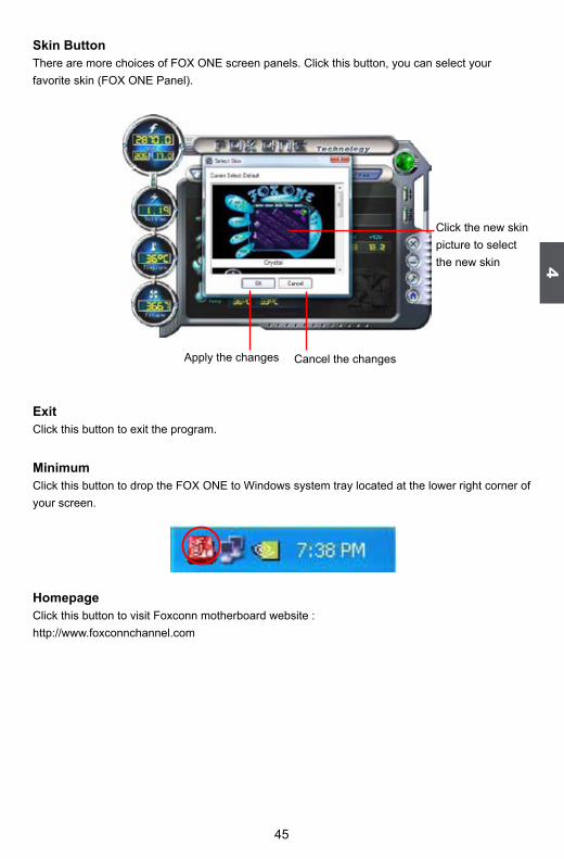
Skin buttonThere are more choices of FOX ONE screen panels. Click this button, you can select your favorite skin (FOX ONE Panel).
exitClick this button to exit the program.
MinimumClick this button to drop the FOX ONE to Windows system tray located at the lower right corner of your screen.
HomepageClick this button to visit Foxconn motherboard website :http://www.foxconnchannel.com
Apply the changes
Click the new skin picture to select the new skin
Cancel the changes
4
46
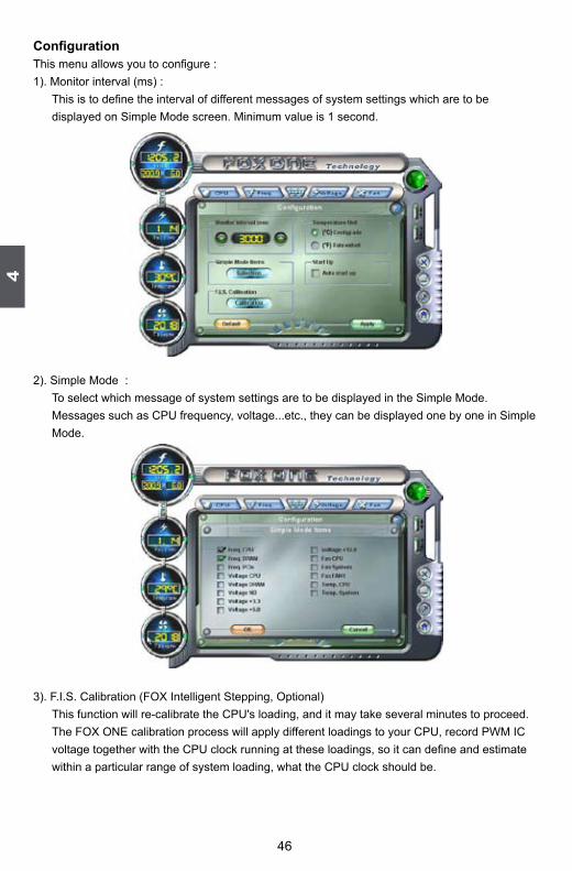
ConfigurationThis menu allows you to configure :1). Monitor interval (ms) :
This is to define the interval of different messages of system settings which are to be displayed on Simple Mode screen. Minimum value is 1 second.
2). Simple Mode :To select which message of system settings are to be displayed in the Simple Mode. Messages such as CPU frequency, voltage...etc., they can be displayed one by one in Simple Mode.
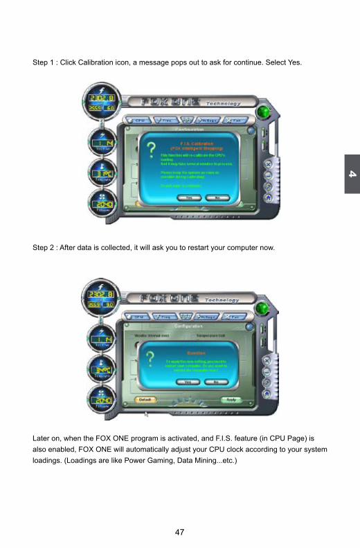
3). F.I.S. Calibration (FOX Intelligent Stepping, Optional)This function will re-calibrate the CPU's loading, and it may take several minutes to proceed. The FOX ONE calibration process will apply different loadings to your CPU, record PWM IC voltage together with the CPU clock running at these loadings, so it can define and estimate within a particular range of system loading, what the CPU clock should be.
4
47
Step 1 : Click Calibration icon, a message pops out to ask for continue. Select Yes.
Step 2 : After data is collected, it will ask you to restart your computer now.
Later on, when the FOX ONE program is activated, and F.I.S. feature (in CPU Page) is also enabled, FOX ONE will automatically adjust your CPU clock according to your system loadings. (Loadings are like Power Gaming, Data Mining...etc.)
4
48
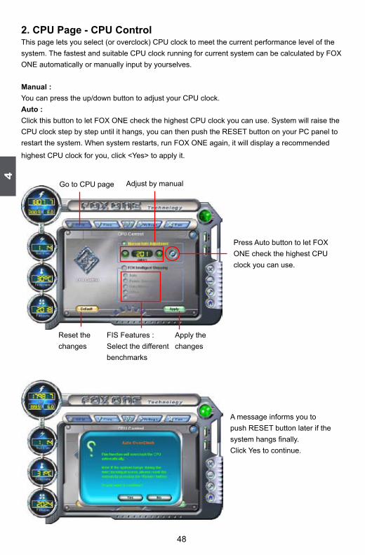
2. CPU Page - CPU ControlThis page lets you select (or overclock) CPU clock to meet the current performance level of the system. The fastest and suitable CPU clock running for current system can be calculated by FOX ONE automatically or manually input by yourselves.
Manual :You can press the up/down button to adjust your CPU clock.Auto :Click this button to let FOX ONE check the highest CPU clock you can use. System will raise the CPU clock step by step until it hangs, you can then push the RESET button on your PC panel to restart the system. When system restarts, run FOX ONE again, it will display a recommended
highest CPU clock for you, click <Yes> to apply it.
A message informs you to push RESET button later if the system hangs finally.Click Yes to continue.
Press Auto button to let FOX ONE check the highest CPU clock you can use.
Go to CPU page
FIS Features :Select the different benchmarks
Adjust by manual
Apply the changes
Reset the changes
4
49
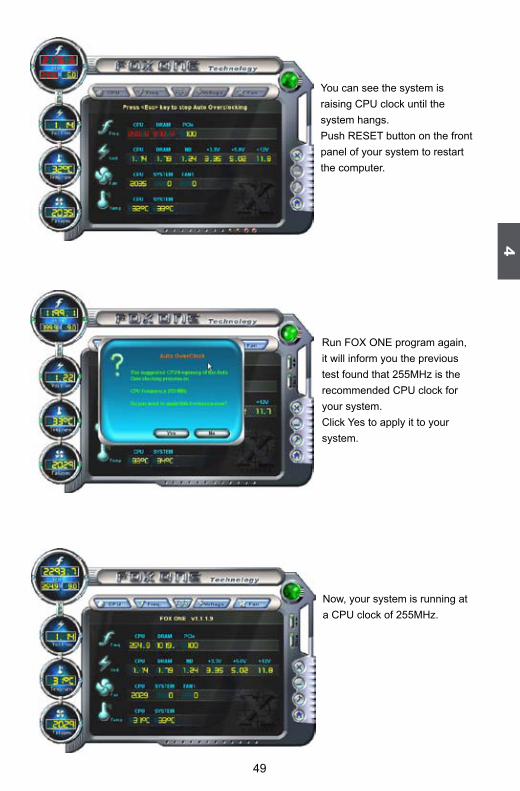
You can see the system is raising CPU clock until the system hangs.Push RESET button on the front panel of your system to restart the computer.
Run FOX ONE program again, it will inform you the previous test found that 255MHz is the recommended CPU clock for your system.Click Yes to apply it to your system.
Now, your system is running at a CPU clock of 255MHz.
4
50
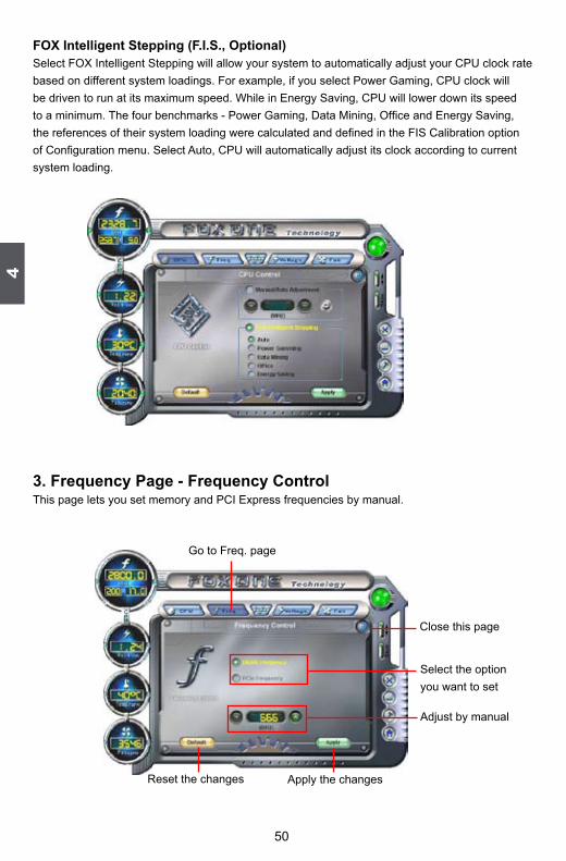
FOX Intelligent Stepping (F.I.S., Optional)Select FOX Intelligent Stepping will allow your system to automatically adjust your CPU clock rate based on different system loadings. For example, if you select Power Gaming, CPU clock will be driven to run at its maximum speed. While in Energy Saving, CPU will lower down its speed to a minimum. The four benchmarks - Power Gaming, Data Mining, Office and Energy Saving, the references of their system loading were calculated and defined in the FIS Calibration option of Configuration menu. Select Auto, CPU will automatically adjust its clock according to current system loading.
3. Frequency Page - Frequency ControlThis page lets you set memory and PCI Express frequencies by manual.
Go to Freq. page
Close this page
Reset the changes Apply the changes
Select the option you want to set
Adjust by manual
4
51
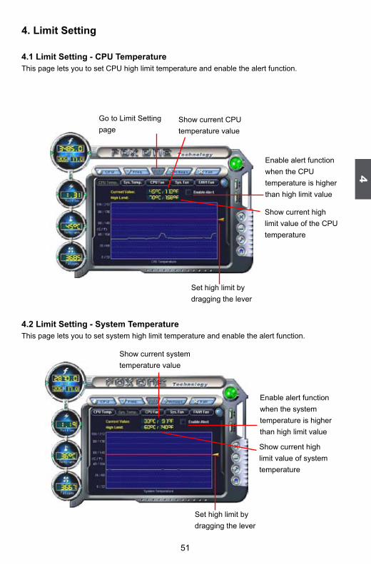
4. Limit Setting
4.1 Limit Setting - CPU TemperatureThis page lets you to set CPU high limit temperature and enable the alert function.
4.2 Limit Setting - System TemperatureThis page lets you to set system high limit temperature and enable the alert function.
Go to Limit Setting page
Set high limit by dragging the lever
Show current CPU temperature value
Enable alert function when the CPU temperature is higher than high limit value
Show current high limit value of the CPU temperature
Set high limit by dragging the lever
Show current system temperature value
Enable alert function when the system temperature is higher than high limit value
Show current high limit value of system temperature
4
52
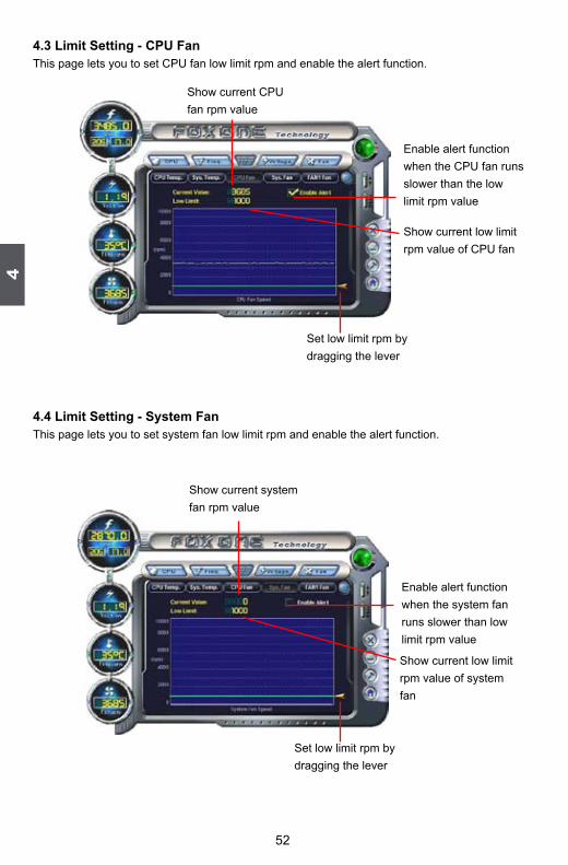
4.3 Limit Setting - CPU FanThis page lets you to set CPU fan low limit rpm and enable the alert function.
4.4 Limit Setting - System FanThis page lets you to set system fan low limit rpm and enable the alert function.
Set low limit rpm by dragging the lever
Show current CPU fan rpm value
Enable alert function when the CPU fan runs slower than the low limit rpm value
Show current low limit rpm value of CPU fan
Set low limit rpm by dragging the lever
Show current system fan rpm value
Enable alert function when the system fan runs slower than low limit rpm value
Show current low limit rpm value of system fan
4
53
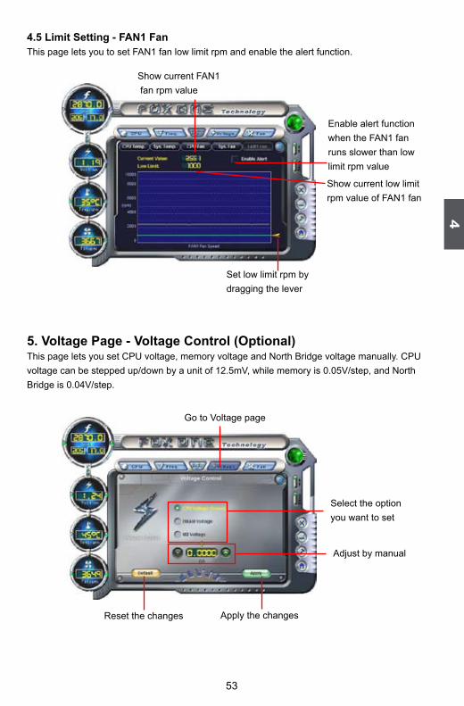
4.5 Limit Setting - FAN1 FanThis page lets you to set FAN1 fan low limit rpm and enable the alert function.
5. Voltage Page - Voltage Control (Optional)This page lets you set CPU voltage, memory voltage and North Bridge voltage manually. CPU voltage can be stepped up/down by a unit of 12.5mV, while memory is 0.05V/step, and North Bridge is 0.04V/step.
Set low limit rpm by dragging the lever
Show current FAN1 fan rpm value
Enable alert function when the FAN1 fan runs slower than low limit rpm value
Show current low limit rpm value of FAN1 fan
Go to Voltage page
Select the option you want to set
Adjust by manual
Reset the changes Apply the changes

4
54
6. Fan Page - Fan ControlThis page lets you enable Smart Fan function or set the fan speed by manual.When Smart Fan is selected, you must use a 4-pin CPU cooler in your system.
Go to Fan page
Set fan speed by dragging the lever
Enable or disable smart fan function
Apply the changes
4
55
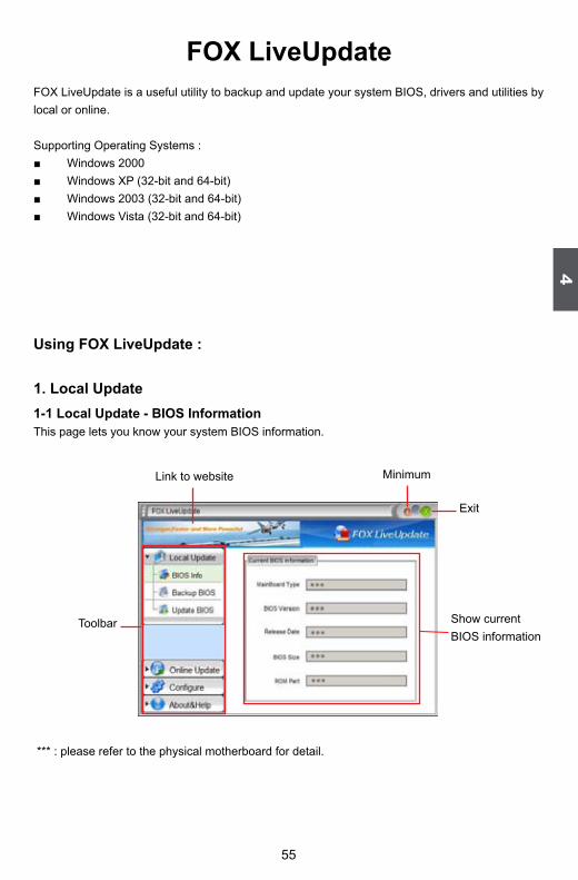
FOX LiveUpdateFOX LiveUpdate is a useful utility to backup and update your system BIOS, drivers and utilities by local or online.
Supporting Operating Systems :■ Windows 2000■ Windows XP (32-bit and 64-bit)■ Windows 2003 (32-bit and 64-bit)■ Windows Vista (32-bit and 64-bit)
Using FOX LiveUpdate :
1. local Update1-1 local Update - bIoS InformationThis page lets you know your system BIOS information.
*** : please refer to the physical motherboard for detail.
Exit
Toolbar
Minimum
Show current BIOS information
Link to website
4
56
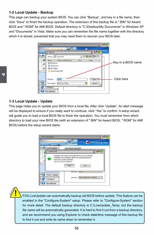
1-2 local Update - backupThis page can backup your system BIOS. You can click “Backup”, and key in a file name, then click “Save” to finish the backup operation. The extension of this backup file is ".BIN" for Award BIOS and ".ROM" for AMI BIOS. Default directory is "C:\Desktop\My Documents" in Windows XP and "Documents" in Vista. Make sure you can remember the file name together with the directory which it is stored, prevented that you may need them to recover your BIOS later.
1-3 local Update - UpdateThis page helps you to update your BIOS from a local file. After click “Update”, An alert message will be displayed to ensure if you really want to continue, click “Yes” to confirm. A setup wizard will guide you to load a local BIOS file to finish the operation. You must remember from which directory to load your new BIOS file (with an extension of ".BIN" for Award BIOS, ".ROM" for AMI BIOS) before the setup wizard starts.
Key in a BIOS name
Click here
FOX LiveUpdate can automatically backup old BIOS before update. This feature can be enabled in the "Configure-System" setup. Please refer to "Configure-System" section for more detail. The default backup directory is C:\LiveUpdate_Temp, but the backup file name will be automatically generated. It is hard to find it out from a backup directory, and we recommend you using Explorer to check date/time message of this backup file to find it out and write its name down to remember it.
CAUT
ION
!
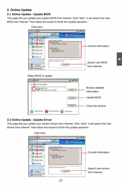
4
57
2. online Update2-1 online Update - Update bIoSThis page lets you update your system BIOS from Internet. Click “start”, it will search the new BIOS from Internet. Then follow the wizard to finish the update operation.
2-2 Online Update - Update DriverThis page lets you update your system drivers from Internet. Click “start”, it will search the new drivers from Internet. Then follow the wizard to finish the update operation.
Click here
Current information
Search new BIOS from Internet
Browse detailed information
Update BIOS
Close the window
Select BIOS to update
Click here
Current information
Search new drivers from Internet
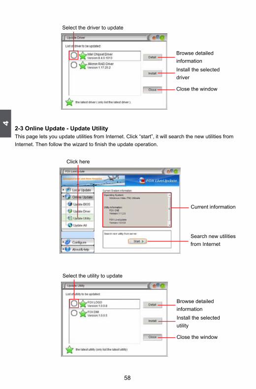
4
58
2-3 online Update - Update UtilityThis page lets you update utilities from Internet. Click “start”, it will search the new utilities from Internet. Then follow the wizard to finish the update operation.
Browse detailed informationInstall the selected driver
Close the window
Select the driver to update
Click here
Current information
Search new utilities from Internet
Browse detailed informationInstall the selected utility
Close the window
Select the utility to update
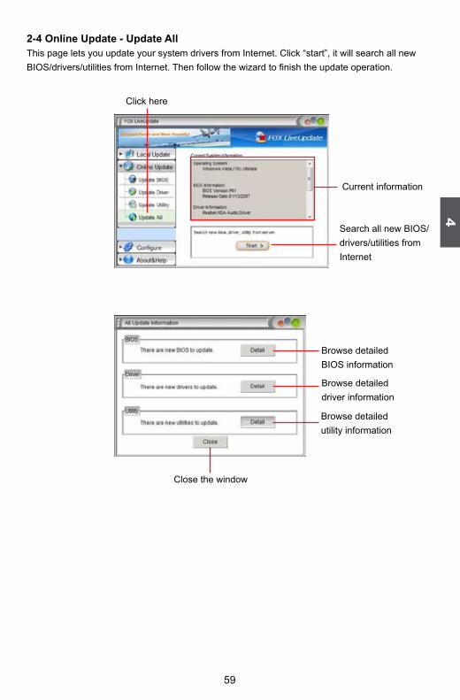
4
59
2-4 online Update - Update AllThis page lets you update your system drivers from Internet. Click “start”, it will search all new BIOS/drivers/utilities from Internet. Then follow the wizard to finish the update operation.
Click here
Current information
Search all new BIOS/drivers/utilities from Internet
Browse detailed BIOS information
Close the window
Browse detailed driver information
Browse detailed utility information
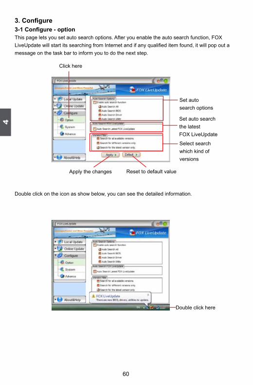
4
60
3. Configure3-1 Configure - optionThis page lets you set auto search options. After you enable the auto search function, FOX LiveUpdate will start its searching from Internet and if any qualified item found, it will pop out a message on the task bar to inform you to do the next step.
Double click on the icon as show below, you can see the detailed information.
Double click here
Apply the changes Reset to default value
Click here
Set auto search options
Select search which kind of versions
Set auto search the latest FOX LiveUpdate
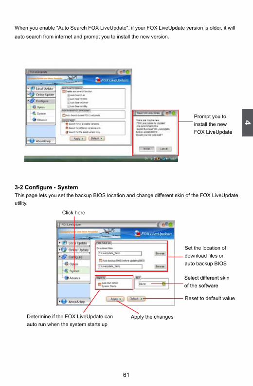
4
61
When you enable "Auto Search FOX LiveUpdate", if your FOX LiveUpdate version is older, it will
auto search from internet and prompt you to install the new version.
3-2 Configure - SystemThis page lets you set the backup BIOS location and change different skin of the FOX LiveUpdate utility.
Click here
Set the location of download files or auto backup BIOS
Determine if the FOX LiveUpdate can auto run when the system starts up
Select different skin of the software
Apply the changes
Reset to default value
Prompt you to install the new FOX LiveUpdate
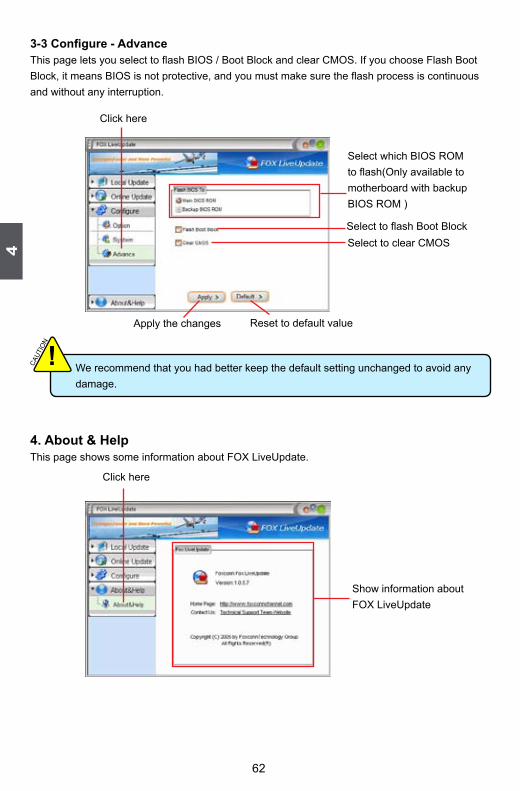
4
62
3-3 Configure - AdvanceThis page lets you select to flash BIOS / Boot Block and clear CMOS. If you choose Flash Boot Block, it means BIOS is not protective, and you must make sure the flash process is continuous and without any interruption.
4. About & HelpThis page shows some information about FOX LiveUpdate.
Click here
Select which BIOS ROM to flash(Only available to motherboard with backup BIOS ROM )
Apply the changes Reset to default value
Select to flash Boot Block Select to clear CMOS
Click here
Show information about FOX LiveUpdate
We recommend that you had better keep the default setting unchanged to avoid any damage.
CAU
TIO
N
!
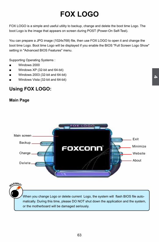
4
63
foX loGoFOX LOGO is a simple and useful utility to backup, change and delete the boot time Logo. The boot Logo is the image that appears on screen during POST (Power-On Self-Test).
You can prepare a JPG image (1024x768) file, then use FOX LOGO to open it and change the boot time Logo. Boot time Logo will be displayed if you enable the BIOS "Full Screen Logo Show" setting in "Advanced BIOS Features" menu.
Supporting Operating Systems :■ Windows 2000■ Windows XP (32-bit and 64-bit)■ Windows 2003 (32-bit and 64-bit)■ Windows Vista (32-bit and 64-bit)
Using FOX LOGO:
Main Page
When you change Logo or delete current Logo, the system will flash BIOS file auto-matically. During this time, please DO NOT shut down the application and the system, or the motherboard will be damaged seriously.
WARNING!
Minimize
Exit
Website
About
Backup
Change
Delete
Main screen
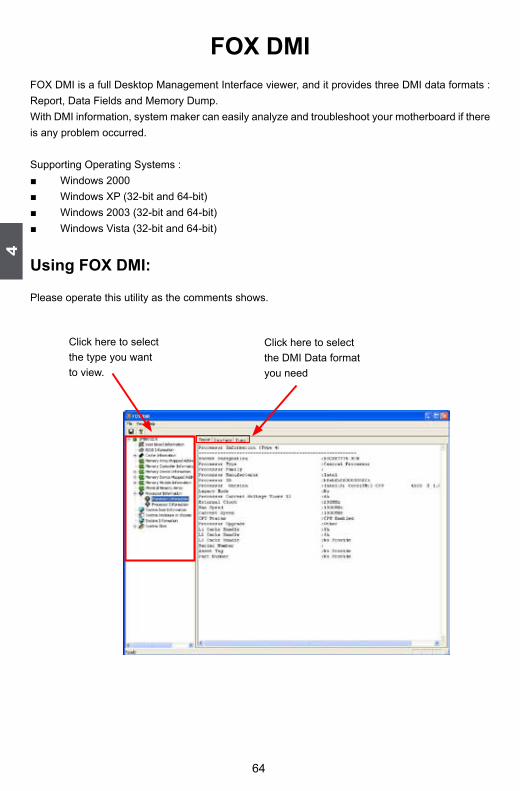
4
64
foX DMIFOX DMI is a full Desktop Management Interface viewer, and it provides three DMI data formats : Report, Data Fields and Memory Dump. With DMI information, system maker can easily analyze and troubleshoot your motherboard if there is any problem occurred.
Supporting Operating Systems :■ Windows 2000■ Windows XP (32-bit and 64-bit)■ Windows 2003 (32-bit and 64-bit)■ Windows Vista (32-bit and 64-bit)
Using FOX DMI:
Please operate this utility as the comments shows.
Click here to select the DMI Data formatyou need
Click here to select the type you want to view.
This chapter will cover two topics :
■ Creating a Bootable Array - Installing a new Windows XP (Vista) in a brand new RAID system.
■ Creating a Non-Bootable Array - Existing Windows XP (Vista) system with new RAID built as data storage.
It includes the following information :
■ RAID Configuration Introduction■ NVIDIA® MediaShield Driver■ Create two RAID Driver Diskettes■ RAID Enable in BIOS■ Select a RAID Array for Use■ Install a New Windows XP■ Setting Up a Non-Bootable RAID Array
The RAID BIOS Setup pictures shown in this chapter are for reference only, please refer to the practical screen.
5
66
Creating a Bootable Array - Installing a new Windows XP (or Vista) in a brand new RAID system.
1. Follow 5-1 to create two RAID driver diskettes.2. Follow 5-2 to set RAID enabled in BIOS.3. Follow 5-3 to select a RAID array for use.4. Follow 5-4 to Install a new Windows Operating System.
What kinds of hardware and software you need here :1. A floppy drive.2. A DVD-ROM drive.3. Several SATA hard disks.4. Two RAID driver diskettes. (Can be created by using motherboard driver CD)5. A motherboard driver CD. 6. Windows XP or Vista Install CD.
Creating a Non-Bootable Array - Existing Windows XP (or Vista)
system with new RAID built as data storage.
Follow 5-5 to go through the processes to build a new RAID array in your existing Windows XP system, it includes :1. Set RAID enabled in BIOS.2. Follow 5-3 to select a RAID array for use.3. Run setup program to install NVIDIA RAID driver into your current Windows XP
system.4. Use Administrative Tools in Control Panel to format new RAID array.
What kinds of hardware and software you need here :1. A DVD-ROM drive.2. Several SATA hard disks.3. A motherboard driver CD.
5
67
RAID Configuration Introduction
RAID (Redundant Array of Independent Disks) is a method for computer data storage schemes that divide and/or replicate data among multiple hard drives. RAID can be designed to provide increased data reliability (fault tolerance) or increased I/O (input/output) performance, or both. The following RAID configurations are provided for users.
There are three major key concepts in RAID: 1. Mirroring : The copying of data to more than one disk; 2. Striping : The splitting of data across more than one disk; 3. Error correction : Where redundant data is stored to allow problems to be detected
and possibly fixed (known as fault tolerance).
Different RAID levels use one or more of these techniques, depending on the system requirements. The main aims of using RAID are to improve reliability, important for protecting information that is critical to a business, for example a database of customer orders; or where speed is important, for example a system that delivers video on demand TV programs to many viewers.
The configuration affects reliability and performance in different ways. The problem with using more disks is that it is more likely that one will go wrong, but by using error checking the total system can be made more reliable by being able to survive and repair the failure. Basic mirroring can speed up reading data as a system can read different data from both the disks, but it may be slow for writing if it insists that both disks must confirm that the data is correctly written. Striping is often used for performance, where it allows sequences of data to be read off multiple disks at the same time. Error checking typically will slow the system down as data needs to be read from several places and compared. The design of RAID systems is therefore a compromise and understanding the requirements of a system is important. Modern disk arrays typically provide the facility to select the appropriate RAID configuration.
RAID is often used in high availability systems, where it is important that the system keeps running as much of the time as possible.
5
68
RAID 0 (Striping) RAID 0 reads and writes sectors of data interleaved among multiple drives. If any disk member fails, it affects the entire array. The disk array data capacity is equal to the number of drive members times the capacity of the smallest member. RAID 0 does not support fault tolerance.
RAID 1 (Mirroring) RAID 1 writes duplicate data onto a pair of drives and reads both sets of data in parallel. If one of the mirrored drives suffers a mechanical failure or does not respond, the remaining drive will continue to function. Due to redundancy, the drive capacity of the array is the capacity of the smallest drive.
RAID 5 (Parity) RAID 5 provides data striping at the byte level and also stripes error correction information. This results in excellent performance and good fault tolerance. Level 5 is one of the most popular implementations of RAID.
RAID 0+1 (Stripe Mirroring)RAID 10 is a combination of striping and mirroring. This configuration provides optimal speed and reliability, but you need four SATA hard disks.
Spanning (JBOD)JBOD stands for “Just a Bunch of Disks”. Each drive is accessed as if it was on a standard SCSI host bus adapter. This is useful when a single drive configuration is needed, but it offers no speed improvement or fault tolerance. A spanned volume is a formatted partition which data is stored on more than one hard disk, yet appears as one volume. Unlike RAID, spanned volumes have no fault-tolerance, so if any disk fails, the data on the whole volume could be lost. Additionally, the system or boot partitions cannot be included in a spanned volume. FAT16/32 and NTFS file systems may be used, and the volume can span up to 32 hard disks.
Comparison Table :
Solution Hard Disks No. Capacity Performance Reliability Application
RAID0 >=2 All Highest Dangerous Look for speed
RAID1 2 50% Read faster Excellent 100% Data backup
RAID5 >=3 N-1 Read fasterWrite slower
Good Limited budget
RAID0+1 >=4(Even number)
Smallest*2
High Excellent Unlimited budget
Span >=1 All none Dangerous Big disk space
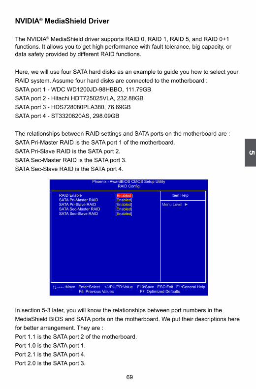
5
69
NVIDIA® MediaShield Driver
The NVIDIA® MediaShield driver supports RAID 0, RAID 1, RAID 5, and RAID 0+1 functions. It allows you to get high performance with fault tolerance, big capacity, or data safety provided by different RAID functions.
Here, we will use four SATA hard disks as an example to guide you how to select your RAID system. Assume four hard disks are connected to the motherboard :SATA port 1 - WDC WD1200JD-98HBBO, 111.79GBSATA port 2 - Hitachi HDT725025VLA, 232.88GBSATA port 3 - HDS728080PLA380, 76.69GBSATA port 4 - ST3320620AS, 298.09GB
The relationships between RAID settings and SATA ports on the motherboard are :SATA Pri-Master RAID is the SATA port 1 of the motherboard.SATA Pri-Slave RAID is the SATA port 2.SATA Sec-Master RAID is the SATA port 3.SATA Sec-Slave RAID is the SATA port 4.
In section 5-3 later, you will know the relationships between port numbers in the MediaShield BIOS and SATA ports on the motherboard. We put their descriptions here for better arrangement. They are :Port 1.1 is the SATA port 2 of the motherboard.Port 1.0 is the SATA port 1.Port 2.1 is the SATA port 4.Port 2.0 is the SATA port 3.
Phoenix - AwardBIOS CMOS Setup UtilityRAID Config
RAID Enable [ IDE] Item Help SATA Pri-Master RAID [Enabled] SATA Pri-Slave RAID [Enabled] Menu Level ► SATA Sec-Master RAID [Enabled] SATA Sec-Slave RAID [Enabled]
↑↓→←:Move Enter:Select +/-/PU/PD:Value F10:Save ESC:Exit F1:General Help F5: Previous Values F7: Optimized Defaults
Enabled
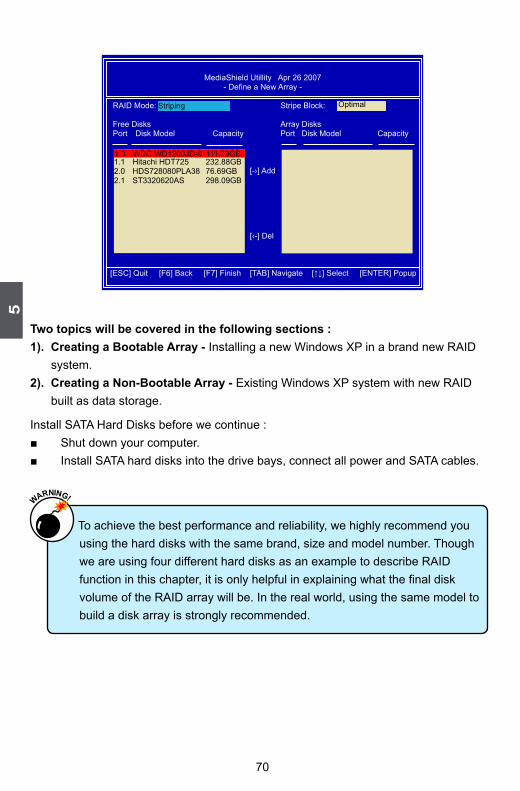
5
70
Two topics will be covered in the following sections :1). Creating a Bootable Array - Installing a new Windows XP in a brand new RAID
system.2). Creating a Non-Bootable Array - Existing Windows XP system with new RAID
built as data storage.
Install SATA Hard Disks before we continue :■ Shut down your computer.■ Install SATA hard disks into the drive bays, connect all power and SATA cables.
To achieve the best performance and reliability, we highly recommend you using the hard disks with the same brand, size and model number. Though we are using four different hard disks as an example to describe RAID function in this chapter, it is only helpful in explaining what the final disk volume of the RAID array will be. In the real world, using the same model to build a disk array is strongly recommended.
WARNING!
MediaShield Utillity Apr 26 2007- Define a New Array -
RAID Mode: Mirrored Stripe Block: Optimal Free Disks Array Disks Port Disk Model Capacity Port Disk Model Capacity
[-›] Add
[‹-] Del
[ESC] Quit [F6] Back [F7] Finish [TAB] Navigate [↑↓] Select [ENTER] Popup
Optimal
0.0 WDC WD1200JD-9 111.79GB1.1 Hitachi HDT725 232.88GB2.0 HDS728080PLA38 76.69GB2.1 ST3320620AS 298.09GB
Striping
1.0 WDC WD1200JD-9 111.79GB
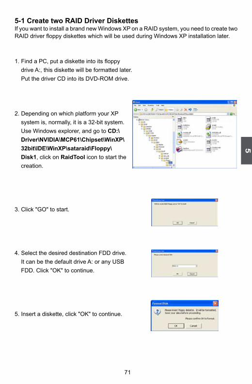
5
71
1. Find a PC, put a diskette into its floppy drive A:, this diskette will be formatted later.
Put the driver CD into its DVD-ROM drive.
2. Depending on which platform your XP system is, normally, it is a 32-bit system. Use Windows explorer, and go to CD:\Driver\NVIDIA\MCP61\Chipset\WinXP\32bit\IDe\WinXP\sataraid\floppy\Disk1, click on RaidTool icon to start the creation.
3. Click "GO" to start.
4. Select the desired destination FDD drive. It can be the default drive A: or any USB FDD. Click "OK" to continue.
5. Insert a diskette, click "OK" to continue.
5-1 Create two RAID Driver Diskettes If you want to install a brand new Windows XP on a RAID system, you need to create two RAID driver floppy diskettes which will be used during Windows XP installation later.
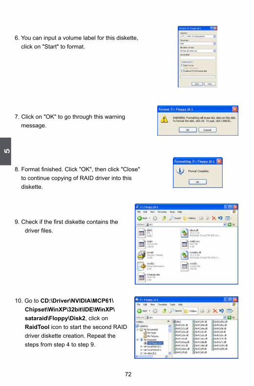
5
72
6. You can input a volume label for this diskette, click on "Start" to format.
7. Click on "OK" to go through this warning message.
8. Format finished. Click "OK", then click "Close" to continue copying of RAID driver into this diskette.
9. Check if the first diskette contains the driver files.
10. Go to CD:\Driver\NVIDIA\MCP61\Chipset\WinXP\32bit\IDe\WinXP\sataraid\floppy\Disk2, click on RaidTool icon to start the second RAID driver diskette creation. Repeat the steps from step 4 to step 9.
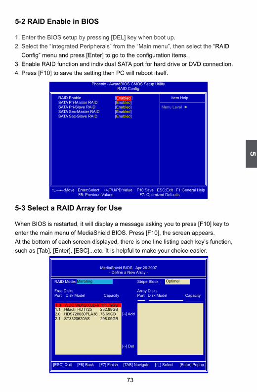
5
73
5-2 RAID enable in bIoS
1. Enter the BIOS setup by pressing [DEL] key when boot up.2. Select the “Integrated Peripherals” from the “Main menu”, then select the “RAID
Config” menu and press [Enter] to go to the configuration items. 3. Enable RAID function and individual SATA port for hard drive or DVD connection. 4. Press [F10] to save the setting then PC will reboot itself.
5-3 Select a RAID Array for Use
When BIOS is restarted, it will display a message asking you to press [F10] key to enter the main menu of MediaShield BIOS. Press [F10], the screen appears.At the bottom of each screen displayed, there is one line listing each key’s function, such as [Tab], [Enter], [ESC]...etc. It is helpful to make your choice easier.
MediaShield BIOS Apr 26 2007- Define a New Array -
RAID Mode: Mirrored Stripe Block: Optimal Free Disks Array Disks Port Disk Model Capacity Port Disk Model Capacity
[-›] Add
[‹-] Del
[ESC] Quit [F6] Back [F7] Finish [TAB] Navigate [↑↓] Select [Enter] Popup
0.0 WDC WD1200JD-9 111.79GB1.1 Hitachi HDT725 232.88GB2.0 HDS728080PLA38 76.69GB2.1 ST3320620AS 298.09GB
Mirroring Optimal
1.0 WDC WD1200JD-9 111.79GB
Phoenix - AwardBIOS CMOS Setup UtilityRAID Config
RAID Enable [ IDE] Item Help SATA Pri-Master RAID [Enabled] SATA Pri-Slave RAID [Enabled] Menu Level ► SATA Sec-Master RAID [Enabled] SATA Sec-Slave RAID [Enabled]
↑↓→←:Move Enter:Select +/-/PU/PD:Value F10:Save ESC:Exit F1:General Help F5: Previous Values F7: Optimized Defaults
Enabled
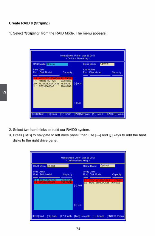
5
74
Create RAID 0 (Striping)
1. Select "Striping" from the RAID Mode. The menu appears :
2. Select two hard disks to build our RAID0 system.3. Press [TAB] to navigate to left drive panel, then use [→] and [↓] keys to add the hard
disks to the right drive panel.
MediaShield Utility Apr 26 2007- Define a New Array -
RAID Mode: Mirrored Stripe Block: Optimal Free Disks Array Disks Port Disk Model Capacity Port Disk Model Capacity
[-›] Add
[‹-] Del
[ESC] Quit [F6] Back [F7] Finish [TAB] Navigate [↑↓] Select [ENTER] Popup
Striping Optimal
1.1 Hitachi HDT725 232.88GB0.3 ST3320620AS 298.09GB
0.0 WDC WD1200JD-9 111.79GB2.0 HDS728080PLA38 76.69GB1.0 WDC WD1200JD-9 111.79GB
2.1 ST3320620AS 298.09GB
MediaShield Utillity Apr 26 2007- Define a New Array -
RAID Mode: Mirrored Stripe Block: Optimal Free Disks Array Disks Port Disk Model Capacity Port Disk Model Capacity
[-›] Add
[‹-] Del
[ESC] Quit [F6] Back [F7] Finish [TAB] Navigate [↑↓] Select [ENTER] Popup
Optimal
0.0 WDC WD1200JD-9 111.79GB1.1 Hitachi HDT725 232.88GB2.0 HDS728080PLA38 76.69GB2.1 ST3320620AS 298.09GB
Striping
1.0 WDC WD1200JD-9 111.79GB
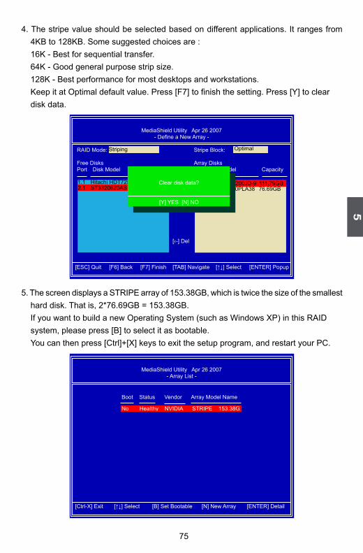
5
75
4. The stripe value should be selected based on different applications. It ranges from 4KB to 128KB. Some suggested choices are :
16K - Best for sequential transfer. 64K - Good general purpose strip size. 128K - Best performance for most desktops and workstations.
Keep it at Optimal default value. Press [F7] to finish the setting. Press [Y] to clear disk data.
5. The screen displays a STRIPE array of 153.38GB, which is twice the size of the smallest hard disk. That is, 2*76.69GB = 153.38GB.If you want to build a new Operating System (such as Windows XP) in this RAID system, please press [B] to select it as bootable.You can then press [Ctrl]+[X] keys to exit the setup program, and restart your PC.
MediaShield Utility Apr 26 2007- Define a New Array -
RAID Mode: Mirrored Stripe Block: Optimal Free Disks Array Disks Port Disk Model Capacity Port Disk Model Capacity
[-›] Add
[‹-] Del
[ESC] Quit [F6] Back [F7] Finish [TAB] Navigate [↑↓] Select [ENTER] Popup
Striping Optimal
1.1 Hitachi HDT725 232.88GB0.3 ST3320620AS 298.09GB
0.0 WDC WD1200JD-9 111.79GB2.0 HDS728080PLA38 76.69GB1.0 WDC WD1200JD-9 111.79GB
2.1 ST3320620AS 298.09GBClear disk data?
[Y] YES [N] NO
MediaShield Utility Apr 26 2007- Array List -
[Ctrl-X] Exit [↑↓] Select [B] Set Bootable [N] New Array [ENTER] Detail
Boot Status Vendor Array Model Name
No Healthy NVIDIA STRIPE 153.38G
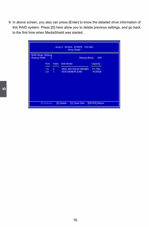
5
76
6. In above screen, you also can press [Enter] to know the detailed drive information of this RAID system. Press [D] here allow you to delete previous settings, and go back to the first time when MediaShield was started.
Array 4 : NVIDIA STRIPE 153.38G- Array Detail -
RAID Mode: Striping Striping Width : 2 Striping Block: 64K
[R] Rebuild [D] Delete [C] Clear Disk [ENTER] Return
Port Index Disk Model Capacity
1.0 0 WDC WD1200JD-98HBB0 111.79G2.0 1 HDS728080PLA380 76.69GB
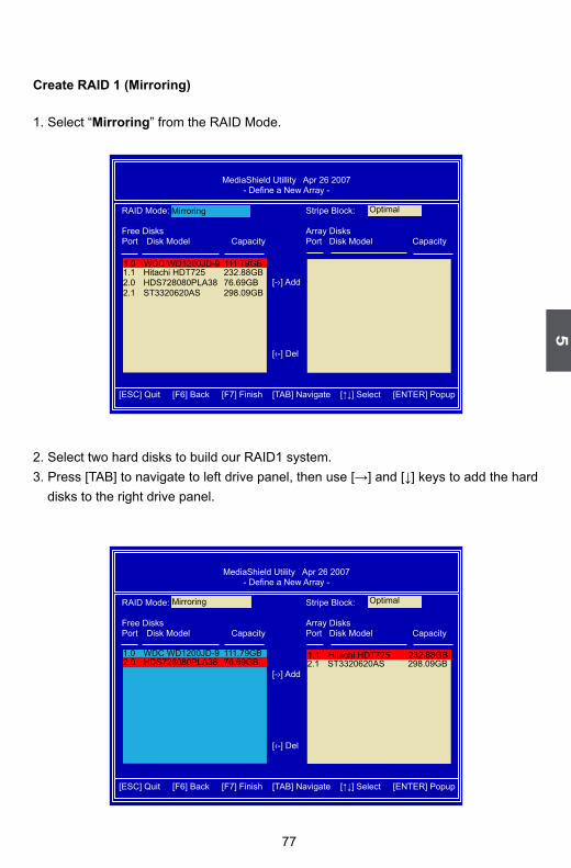
5
77
Create RAID 1 (Mirroring)
1. Select “Mirroring” from the RAID Mode.
2. Select two hard disks to build our RAID1 system.3. Press [TAB] to navigate to left drive panel, then use [→] and [↓] keys to add the hard
disks to the right drive panel.
MediaShield Utillity Apr 26 2007- Define a New Array -
RAID Mode: Mirrored Stripe Block: Optimal Free Disks Array Disks Port Disk Model Capacity Port Disk Model Capacity
[-›] Add
[‹-] Del
[ESC] Quit [F6] Back [F7] Finish [TAB] Navigate [↑↓] Select [ENTER] Popup
Optimal
0.0 WDC WD1200JD-9 111.79GB1.1 Hitachi HDT725 232.88GB2.0 HDS728080PLA38 76.69GB2.1 ST3320620AS 298.09GB
Mirroring
1.0 WDC WD1200JD-9 111.79GB
MediaShield Utility Apr 26 2007- Define a New Array -
RAID Mode: Mirrored Stripe Block: Optimal Free Disks Array Disks Port Disk Model Capacity Port Disk Model Capacity
[-›] Add
[‹-] Del
[ESC] Quit [F6] Back [F7] Finish [TAB] Navigate [↑↓] Select [ENTER] Popup
Mirroring Optimal
1.0 WDC WD1200JD-9 111.79GB 0.0 WDC WD1200JD-9 111.79GB2.1 ST3320620AS 298.09GB1.1 Hitachi HDT725 232.88GB
2.0 HDS728080PLA38 76.69GB
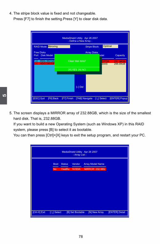
5
78
4. The stripe block value is fixed and not changeable. Press [F7] to finish the setting.Press [Y] to clear disk data.
5. The screen displays a MIRROR array of 232.88GB, which is the size of the smallest hard disk. That is, 232.88GB.If you want to build a new Operating System (such as Windows XP) in this RAID system, please press [B] to select it as bootable.You can then press [Ctrl]+[X] keys to exit the setup program, and restart your PC.
MediaShield Utility Apr 26 2007- Define a New Array -
RAID Mode: Mirrored Stripe Block: Optimal Free Disks Array Disks Port Disk Model Capacity Port Disk Model Capacity
[-›] Add
[‹-] Del
[ESC] Quit [F6] Back [F7] Finish [TAB] Navigate [↑↓] Select [ENTER] Popup
Mirroring Optimal
1.0 WDC WD1200JD-9 111.79GB 0.0 WDC WD1200JD-9 111.79GB2.1 ST3320620AS 298.09GB1.1 Hitachi HDT725 232.88GB
2.0 HDS728080PLA38 76.69GBClear disk data?
[Y] YES [N] NO
MediaShield Utility Apr 26 2007- Array List -
[Ctrl-X] Exit [↑↓] Select [B] Set Bootable [N] New Array [ENTER] Detail
Boot Status Vendor Array Model Name
No Healthy NVIDIA MIRROR 232.88G
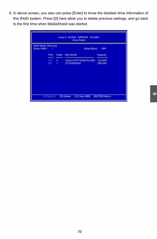
5
79
6. In above screen, you also can press [Enter] to know the detailed drive information of this RAID system. Press [D] here allow you to delete previous settings, and go back to the first time when MediaShield was started.
Array 4 : NVIDIA MIRROR 232.88G- Array Detail -
RAID Mode: Mirroring Stripe Width : 1 Stripe Block: 64K
[R] Rebuild [D] Delete [C] Clear MBR [ENTER] Return
Port Index Disk Model Capacity
1.1 0 Hitachi HDT725025VLA380 232.88G 2.1 1 ST3320620AS 298.09G
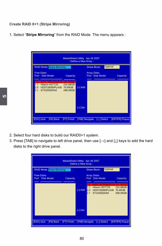
5
80
Create RAID 0+1 (Stripe Mirroring)
1. Select “Stripe Mirroring” from the RAID Mode. The menu appears :
2. Select four hard disks to build our RAID0+1 system.3. Press [TAB] to navigate to left drive panel, then use [→] and [↓] keys to add the hard
disks to the right drive panel.
MediaShield Utillity Apr 26 2007- Define a New Array -
RAID Mode: Mirrored Stripe Block: Optimal Free Disks Array Disks Port Disk Model Capacity Port Disk Model Capacity
[-›] Add
[‹-] Del
[ESC] Quit [F6] Back [F7] Finish [TAB] Navigate [↑↓] Select [ENTER] Popup
Optimal
0.0 WDC WD1200JD-9 111.79GB1.1 Hitachi HDT725 232.88GB2.0 HDS728080PLA38 76.69GB2.1 ST3320620AS 298.09GB
Stripe Mirroring
1.0 WDC WD1200JD-9 111.79GB
MediaShield Utillity Apr 26 2007- Define a New Array -
RAID Mode: Mirrored Stripe Block: Optimal Free Disks Array Disks Port Disk Model Capacity Port Disk Model Capacity
[-›] Add
[‹-] Del
[ESC] Quit [F6] Back [F7] Finish [TAB] Navigate [↑↓] Select [ENTER] Popup
OptimalStripe Mirroring
0.0 WDC WD1200JD-9 111.79GB1.1 Hitachi HDT725 232.88GB2.0 HDS728080PLA38 76.69GB2.1 ST3320620AS 298.09GB
1.0 WDC WD1200JD-9 111.79GB
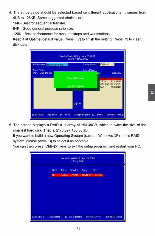
5
81
4. The stripe value should be selected based on different applications. It ranges from 4KB to 128KB. Some suggested choices are :
16K - Best for sequential transfer. 64K - Good general purpose strip size. 128K - Best performance for most desktops and workstations.
Keep it at Optimal default value. Press [F7] to finish the setting. Press [Y] to clear disk data.
5. The screen displays a RAID 0+1 array of 153.38GB, which is twice the size of the smallest hard disk. That is, 2*76.69= 153.38GB.If you want to build a new Operating System (such as Windows XP) in this RAID system, please press [B] to select it as bootable.You can then press [Ctrl]+[X] keys to exit the setup program, and restart your PC.
MediaShield Utillity Apr 26 2007- Define a New Array -
RAID Mode: Mirrored Stripe Block: Optimal Free Disks Array Disks Port Disk Model Capacity Port Disk Model Capacity
[-›] Add
[‹-] Del
[ESC] Quit [F6] Back [F7] Finish [TAB] Navigate [↑↓] Select [ENTER] Popup
OptimalStripe Mirroring
0.0 WDC WD1200JD-9 111.79GB1.1 Hitachi HDT725 232.88GB2.0 HDS728080PLA38 76.69GB2.1 ST3320620AS 298.09GB
1.0 WDC WD1200JD-9 111.79GBClear disk data?
[Y] YES [N] NO
MediaShield BIOS Apr 26 2007- Array List -
[Ctrl-X] Exit [↑↓] Select [B] Set Bootable [N] New Array [ENTER] Detail
Boot Status Vendor Array Size
No Healthy NVIDIA RAID 0+1 153.38G
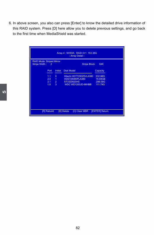
5
82
6. In above screen, you also can press [Enter] to know the detailed drive information of this RAID system. Press [D] here allow you to delete previous settings, and go back to the first time when MediaShield was started.
Array 4 : NVIDIA RAID 0+1 153.38G- Array Detail -
RAID Mode: Striped Mirror Stripe Width : 2 Stripe Block: 64K
[R] Rebuild [D] Delete [C] Clear MBR [ENTER] Return
Port Index Disk Model Capacity
1.1 0 Hitachi HDT725025VLA380 232.88G2.0 1 HDS728080PLA380 76.69GB2.1 2 ST3320620AS 298.09G 1.0 3 WDC WD1200JD-98HBB 111.79G
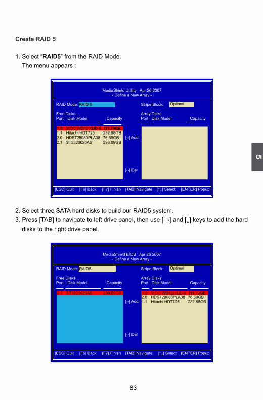
5
83
Create RAID 5
1. Select “RAID5” from the RAID Mode.The menu appears :
2. Select three SATA hard disks to build our RAID5 system.3. Press [TAB] to navigate to left drive panel, then use [→] and [↓] keys to add the hard
disks to the right drive panel.
MediaShield BIOS Apr 26 2007- Define a New Array -
RAID Mode: Mirrored Stripe Block: Optimal Free Disks Array Disks Port Disk Model Capacity Port Disk Model Capacity
[-›] Add
[‹-] Del
[ESC] Quit [F6] Back [F7] Finish [TAB] Navigate [↑↓] Select [ENTER] Popup
RAID5 Optimal
0.0 WDC WD1200JD-9 111.79GB2.0 HDS728080PLA38 76.69GB1.1 Hitachi HDT725 232.88GB
1.0 WDC WD1200JD-9 111.79GB2.1 ST3320620AS 298.09GB
MediaShield Utillity Apr 26 2007- Define a New Array -
RAID Mode: Mirrored Stripe Block: Optimal Free Disks Array Disks Port Disk Model Capacity Port Disk Model Capacity
[-›] Add
[‹-] Del
[ESC] Quit [F6] Back [F7] Finish [TAB] Navigate [↑↓] Select [ENTER] Popup
Optimal
0.0 WDC WD1200JD-9 111.79GB1.1 Hitachi HDT725 232.88GB2.0 HDS728080PLA38 76.69GB2.1 ST3320620AS 298.09GB
RAID 5
1.0 WDC WD1200JD-9 111.79GB
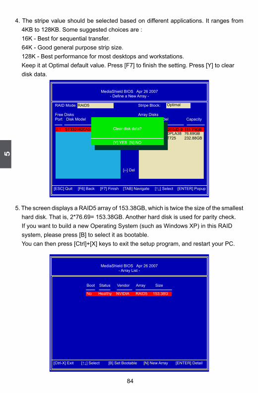
5
84
4. The stripe value should be selected based on different applications. It ranges from 4KB to 128KB. Some suggested choices are :
16K - Best for sequential transfer. 64K - Good general purpose strip size. 128K - Best performance for most desktops and workstations.
Keep it at Optimal default value. Press [F7] to finish the setting. Press [Y] to clear disk data.
5. The screen displays a RAID5 array of 153.38GB, which is twice the size of the smallest hard disk. That is, 2*76.69= 153.38GB. Another hard disk is used for parity check.If you want to build a new Operating System (such as Windows XP) in this RAID system, please press [B] to select it as bootable.You can then press [Ctrl]+[X] keys to exit the setup program, and restart your PC.
MediaShield BIOS Apr 26 2007- Array List -
[Ctrl-X] Exit [↑↓] Select [B] Set Bootable [N] New Array [ENTER] Detail
Boot Status Vendor Array Size
No Healthy NVIDIA RAID5 153.38G
MediaShield BIOS Apr 26 2007- Define a New Array -
RAID Mode: Mirrored Stripe Block: Optimal Free Disks Array Disks Port Disk Model Capacity Port Disk Model Capacity
[-›] Add
[‹-] Del
[ESC] Quit [F6] Back [F7] Finish [TAB] Navigate [↑↓] Select [ENTER] Popup
RAID5 Optimal
0.0 WDC WD1200JD-9 111.79GB2.0 HDS728080PLA38 76.69GB1.1 Hitachi HDT725 232.88GB
1.0 WDC WD1200JD-9 111.79GB2.1 ST3320620AS 298.09GBClear disk data?
[Y] YES [N] NO
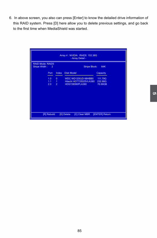
5
85
6. In above screen, you also can press [Enter] to know the detailed drive information of this RAID system. Press [D] here allow you to delete previous settings, and go back to the first time when MediaShield was started.
Array 4 : NVIDIA RAID5 153.38G- Array Detail -
RAID Mode: RAID5 Stripe Width : 2 Stripe Block: 64K
[R] Rebuild [D] Delete [C] Clear MBR [ENTER] Return
Port Index Disk Model Capacity
1.0 0 WDC WD1200JD-98HBB0 111.79G1.1 1 Hitachi HDT725025VLA380 232.88G2.0 2 HDS728080PLA380 76.69GB
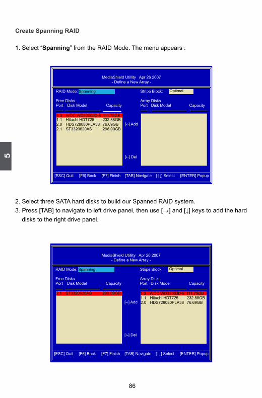
5
86
Create Spanning RAID
1. Select “Spanning” from the RAID Mode. The menu appears :
2. Select three SATA hard disks to build our Spanned RAID system.3. Press [TAB] to navigate to left drive panel, then use [→] and [↓] keys to add the hard
disks to the right drive panel.
MediaShield Utillity Apr 26 2007- Define a New Array -
RAID Mode: Mirrored Stripe Block: Optimal Free Disks Array Disks Port Disk Model Capacity Port Disk Model Capacity
[-›] Add
[‹-] Del
[ESC] Quit [F6] Back [F7] Finish [TAB] Navigate [↑↓] Select [ENTER] Popup
Optimal
0.0 WDC WD1200JD-9 111.79GB1.1 Hitachi HDT725 232.88GB2.0 HDS728080PLA38 76.69GB2.1 ST3320620AS 298.09GB
Spanning
1.0 WDC WD1200JD-9 111.79GB
MediaShield Utillity Apr 26 2007- Define a New Array -
RAID Mode: Mirrored Stripe Block: Optimal Free Disks Array Disks Port Disk Model Capacity Port Disk Model Capacity
[-›] Add
[‹-] Del
[ESC] Quit [F6] Back [F7] Finish [TAB] Navigate [↑↓] Select [ENTER] Popup
Optimal
1.0 WDC WD1200JD-9 111.79GB1.1 Hitachi HDT725 232.88GB2.0 HDS728080PLA38 76.69GB
Spanning
2.1 ST3320620AS 298.09GB 1.0 WDC WD1200JD-9 111.79GB
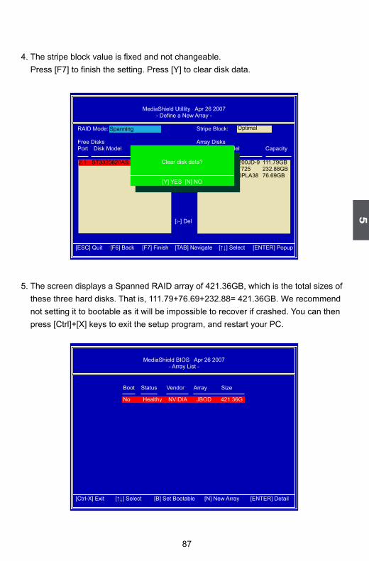
5
87
4. The stripe block value is fixed and not changeable. Press [F7] to finish the setting. Press [Y] to clear disk data.
5. The screen displays a Spanned RAID array of 421.36GB, which is the total sizes of these three hard disks. That is, 111.79+76.69+232.88= 421.36GB. We recommend not setting it to bootable as it will be impossible to recover if crashed. You can then press [Ctrl]+[X] keys to exit the setup program, and restart your PC.
MediaShield Utillity Apr 26 2007- Define a New Array -
RAID Mode: Mirrored Stripe Block: Optimal Free Disks Array Disks Port Disk Model Capacity Port Disk Model Capacity
[-›] Add
[‹-] Del
[ESC] Quit [F6] Back [F7] Finish [TAB] Navigate [↑↓] Select [ENTER] Popup
Optimal
1.0 WDC WD1200JD-9 111.79GB1.1 Hitachi HDT725 232.88GB2.0 HDS728080PLA38 76.69GB
Spanning
2.1 ST3320620AS 298.09GBClear disk data?
[Y] YES [N] NO
MediaShield BIOS Apr 26 2007- Array List -
[Ctrl-X] Exit [↑↓] Select [B] Set Bootable [N] New Array [ENTER] Detail
Boot Status Vendor Array Size
No Healthy NVIDIA JBOD 421.36G
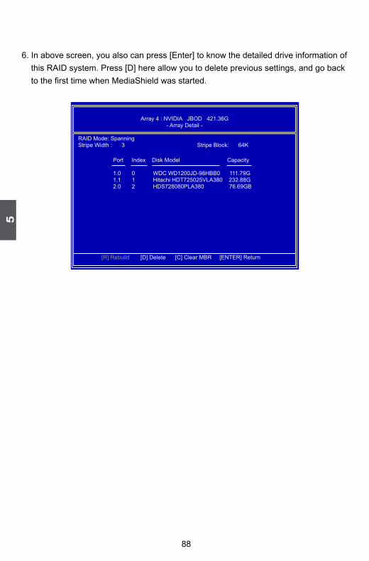
5
88
6. In above screen, you also can press [Enter] to know the detailed drive information of this RAID system. Press [D] here allow you to delete previous settings, and go back to the first time when MediaShield was started.
Array 4 : NVIDIA JBOD 421.36G- Array Detail -
RAID Mode: Spanning Stripe Width : 3 Stripe Block: 64K
[R] Rebuild [D] Delete [C] Clear MBR [ENTER] Return
Port Index Disk Model Capacity
1.0 0 WDC WD1200JD-98HBB0 111.79G1.1 1 Hitachi HDT725025VLA380 232.88G 2.0 2 HDS728080PLA380 76.69GB
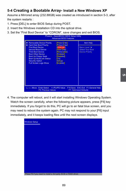
5
89
5-4 Creating a Bootable Array- Install a New Windows XPAssume a Mirrored array (232.88GB) was created as introduced in section 5-3, after the system restarts :1. Press [DEL] to enter BIOS Setup during POST.2. Insert the Windows installation CD into the optical drive.3. Set the “First Boot Device” to “CDROM”, save changes and exit BIOS.
4. The computer will reboot, and it will start installing Windows Operating System. Watch the screen carefully, when the following picture appears, press [F6] key
immediately. If you forgot to do this, PC will go to an fatal blue screen, and you may need to reboot the system again. PC may not respond to your [F6] input immediately, and it keeps loading files until the next screen displays.
Windows Setup
Press F6 if you need to install a 3rd party SCSI or RAID driver.
Phoenix - AwardBIOS CMOS Setup UtilityAdvanced BIOS Features
► Removable Device Priority [Press Enter] Item Help ► Hard Disk Boot Priority [Press Enter] First Boot Device [ CDROM] Menu Level ► Second Boot Device [Hard Disk] Select Your Boot Third Boot Device [Removable] Device Priority Boot Other Device [Enabled] Boot Up Floppy Seek [Disabled] Boot Up NumLock Status [On] Security Option [Setup] Full Screen Logo Show [Enabled]
↑↓→←:Move Enter:Select +/-/PU/PD:Value F10:Save ESC:Exit F1:General Help F5: Previous Values F7: Optimized Defaults
CDROM
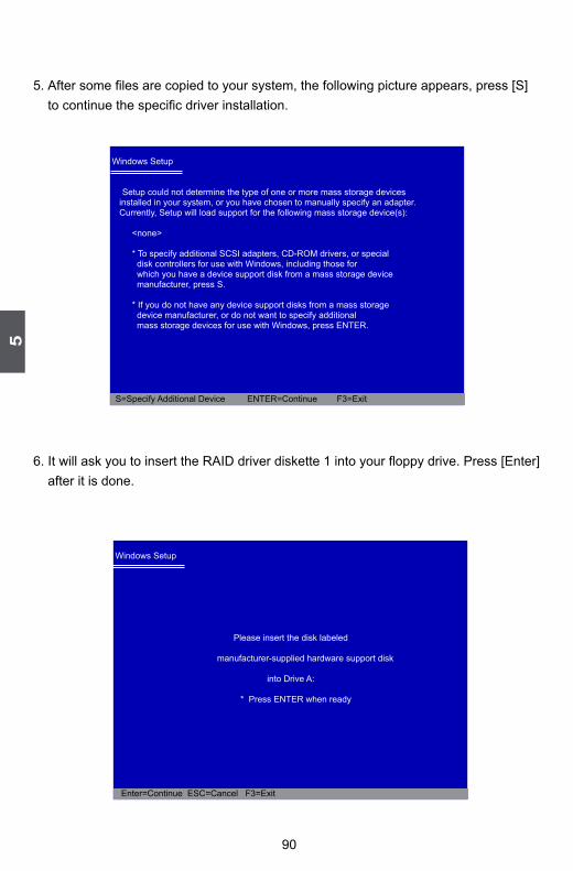
5
90
5. After some files are copied to your system, the following picture appears, press [S] to continue the specific driver installation.
6. It will ask you to insert the RAID driver diskette 1 into your floppy drive. Press [Enter] after it is done.
Windows Setup
Please insert the disk labeled
manufacturer-supplied hardware support disk
into Drive A:
* Press ENTER when ready
Enter=Continue ESC=Cancel F3=Exit
Windows Setup
Setup could not determine the type of one or more mass storage devices installed in your system, or you have chosen to manually specify an adapter. Currently, Setup will load support for the following mass storage device(s):
<none>
* To specify additional SCSI adapters, CD-ROM drivers, or special disk controllers for use with Windows, including those for which you have a device support disk from a mass storage device manufacturer, press S.
* If you do not have any device support disks from a mass storage device manufacturer, or do not want to specify additional mass storage devices for use with Windows, press ENTER.
S=Specify Additional Device ENTER=Continue F3=Exit
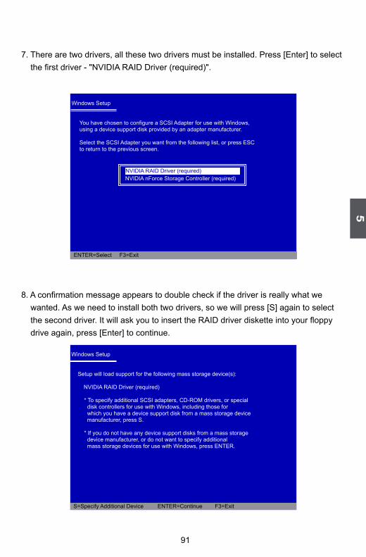
5
91
7. There are two drivers, all these two drivers must be installed. Press [Enter] to select the first driver - "NVIDIA RAID Driver (required)".
8. A confirmation message appears to double check if the driver is really what we wanted. As we need to install both two drivers, so we will press [S] again to select the second driver. It will ask you to insert the RAID driver diskette into your floppy drive again, press [Enter] to continue.
Windows Setup
You have chosen to configure a SCSI Adapter for use with Windows,using a device support disk provided by an adapter manufacturer.
Select the SCSI Adapter you want from the following list, or press ESCto return to the previous screen.
ENTER=Select F3=Exit
NVIDIA nForce Storage Controller (required)NVIDIA RAID Driver (required)
Windows Setup
Setup will load support for the following mass storage device(s):
NVIDIA RAID Driver (required)
* To specify additional SCSI adapters, CD-ROM drivers, or special disk controllers for use with Windows, including those for which you have a device support disk from a mass storage device manufacturer, press S.
* If you do not have any device support disks from a mass storage device manufacturer, or do not want to specify additional mass storage devices for use with Windows, press ENTER.
S=Specify Additional Device ENTER=Continue F3=Exit
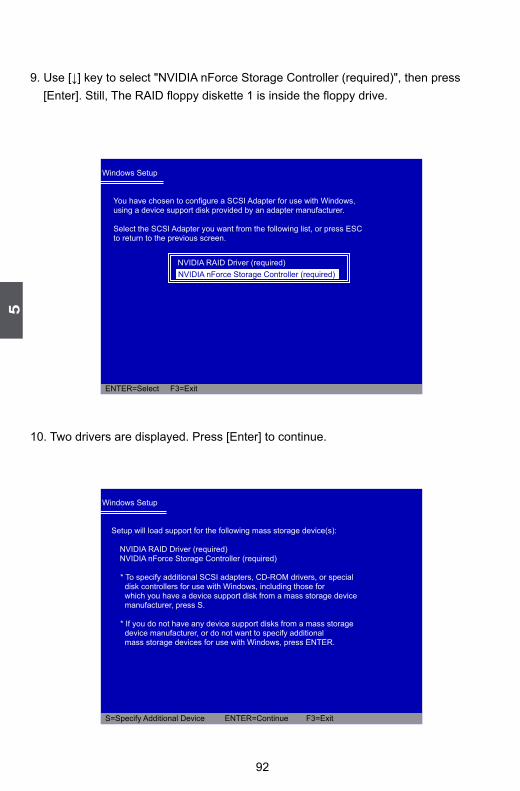
5
92
9. Use [↓] key to select "NVIDIA nForce Storage Controller (required)", then press [Enter]. Still, The RAID floppy diskette 1 is inside the floppy drive.
10. Two drivers are displayed. Press [Enter] to continue.
Windows Setup
Setup will load support for the following mass storage device(s):
NVIDIA RAID Driver (required) NVIDIA nForce Storage Controller (required)
* To specify additional SCSI adapters, CD-ROM drivers, or special disk controllers for use with Windows, including those for which you have a device support disk from a mass storage device manufacturer, press S.
* If you do not have any device support disks from a mass storage device manufacturer, or do not want to specify additional mass storage devices for use with Windows, press ENTER.
S=Specify Additional Device ENTER=Continue F3=Exit
Windows Setup
You have chosen to configure a SCSI Adapter for use with Windows,using a device support disk provided by an adapter manufacturer.
Select the SCSI Adapter you want from the following list, or press ESCto return to the previous screen.
ENTER=Select F3=Exit
NVIDIA nForce Storage Controller (required)NVIDIA RAID Driver (required)NVIDIA nForce Storage Controller (required)
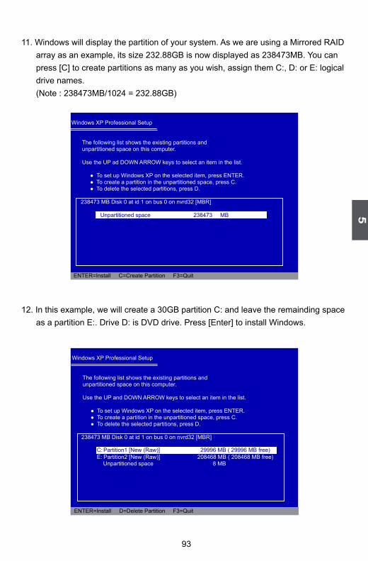
5
93
11. Windows will display the partition of your system. As we are using a Mirrored RAID array as an example, its size 232.88GB is now displayed as 238473MB. You can press [C] to create partitions as many as you wish, assign them C:, D: or E: logical drive names. (Note : 238473MB/1024 = 232.88GB)
12. In this example, we will create a 30GB partition C: and leave the remainding space as a partition E:. Drive D: is DVD drive. Press [Enter] to install Windows.
Windows XP Professional Setup
The following list shows the existing partitions andunpartitioned space on this computer.
Use the UP ad DOWN ARROW keys to select an item in the list.
● To set up Windows XP on the selected item, press ENTER. ● To create a partition in the unpartitioned space, press C. ● To delete the selected partitions, press D.
238473 MB Disk 0 at id 1 on bus 0 on nvrd32 [MBR]
ENTER=Install C=Create Partition F3=Quit
Unpartitioned space 238473 MB
Windows XP Professional Setup
The following list shows the existing partitions andunpartitioned space on this computer.
Use the UP and DOWN ARROW keys to select an item in the list.
● To set up Windows XP on the selected item, press ENTER. ● To create a partition in the unpartitioned space, press C. ● To delete the selected partitions, press D.
238473 MB Disk 0 at id 1 on bus 0 on nvrd32 [MBR]
E: Partition2 [New (Raw)] 208468 MB ( 208468 MB free) Unpartitioned space 8 MB
ENTER=Install D=Delete Partition F3=Quit
C: Partition1 [New (Raw)] 29996 MB ( 29996 MB free)
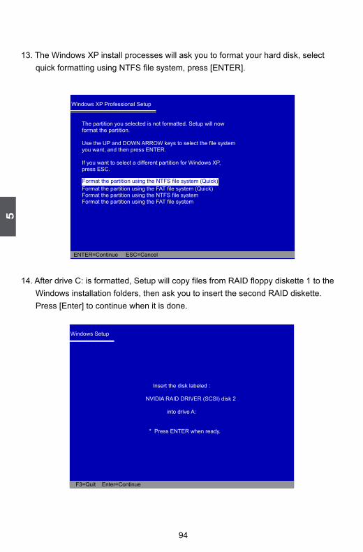
5
94
13. The Windows XP install processes will ask you to format your hard disk, select quick formatting using NTFS file system, press [ENTER].
14. After drive C: is formatted, Setup will copy files from RAID floppy diskette 1 to the Windows installation folders, then ask you to insert the second RAID diskette. Press [Enter] to continue when it is done.
Windows XP Professional Setup
The partition you selected is not formatted. Setup will nowformat the partition.
Use the UP and DOWN ARROW keys to select the file systemyou want, and then press ENTER.
If you want to select a different partition for Windows XP,press ESC.
Format the partition using the NTFS file system (Quick)Format the partition using the FAT file system (Quick)Format the partition using the NTFS file systemFormat the partition using the FAT file system
ENTER=Continue ESC=Cancel
Format the partition using the NTFS file system (Quick)
Windows Setup
Insert the disk labeled :
NVIDIA RAID DRIVER (SCSI) disk 2
into drive A:
* Press ENTER when ready.
F3=Quit Enter=Continue
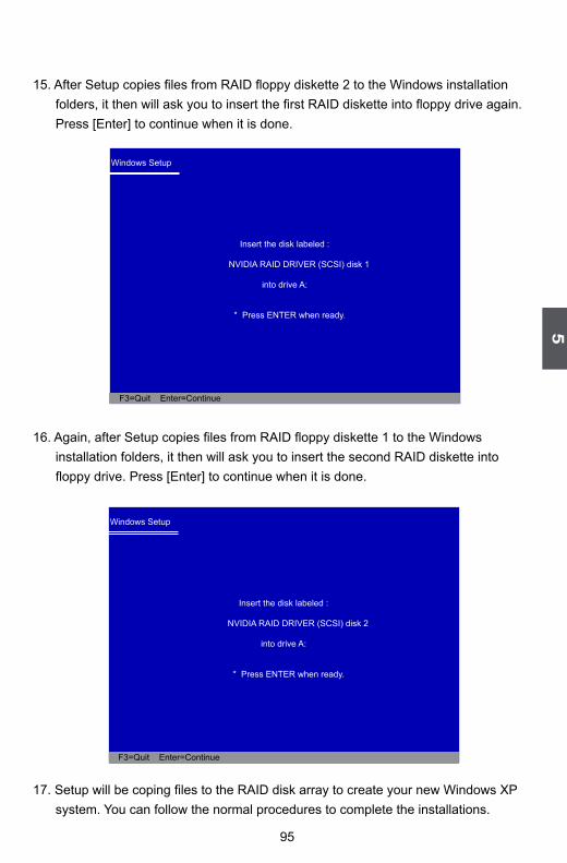
5
95
15. After Setup copies files from RAID floppy diskette 2 to the Windows installation folders, it then will ask you to insert the first RAID diskette into floppy drive again. Press [Enter] to continue when it is done.
16. Again, after Setup copies files from RAID floppy diskette 1 to the Windows installation folders, it then will ask you to insert the second RAID diskette into floppy drive. Press [Enter] to continue when it is done.
17. Setup will be coping files to the RAID disk array to create your new Windows XP system. You can follow the normal procedures to complete the installations.
Windows Setup
Insert the disk labeled :
NVIDIA RAID DRIVER (SCSI) disk 1
into drive A:
* Press ENTER when ready.
F3=Quit Enter=Continue
Windows Setup
Insert the disk labeled :
NVIDIA RAID DRIVER (SCSI) disk 2
into drive A:
* Press ENTER when ready.
F3=Quit Enter=Continue
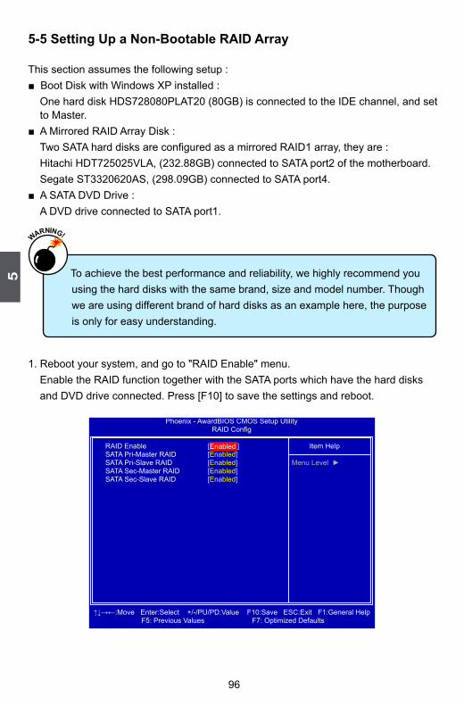
5
96
5-5 Setting Up a Non-Bootable RAID Array
This section assumes the following setup :■ Boot Disk with Windows XP installed :
One hard disk HDS728080PLAT20 (80GB) is connected to the IDE channel, and set to Master.
■ A Mirrored RAID Array Disk : Two SATA hard disks are configured as a mirrored RAID1 array, they are :Hitachi HDT725025VLA, (232.88GB) connected to SATA port2 of the motherboard.Segate ST3320620AS, (298.09GB) connected to SATA port4.
■ A SATA DVD Drive : A DVD drive connected to SATA port1.
1. Reboot your system, and go to "RAID Enable" menu. Enable the RAID function together with the SATA ports which have the hard disks and DVD drive connected. Press [F10] to save the settings and reboot.
To achieve the best performance and reliability, we highly recommend you using the hard disks with the same brand, size and model number. Though we are using different brand of hard disks as an example here, the purpose is only for easy understanding.
WARNING!
Phoenix - AwardBIOS CMOS Setup UtilityRAID Config
RAID Enable [ IDE] Item Help SATA Pri-Master RAID [Enabled] SATA Pri-Slave RAID [Enabled] Menu Level ► SATA Sec-Master RAID [Enabled] SATA Sec-Slave RAID [Enabled]
↑↓→←:Move Enter:Select +/-/PU/PD:Value F10:Save ESC:Exit F1:General Help F5: Previous Values F7: Optimized Defaults
Enabled
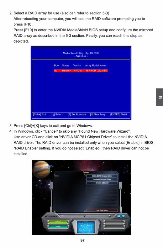
5
97
2. Select a RAID array for use (also can refer to section 5-3) After rebooting your computer, you will see the RAID software prompting you to press [F10].Press [F10] to enter the NVIDIA MediaShield BIOS setup and configure the mirrored RAID array as described in the 5-3 section. Finally, you can reach this step as depicted.
3. Press [Ctrl]+[X] keys to exit and go to Windows.4. In Windows, click "Cancel" to skip any "Found New Hardware Wizard".
Use driver CD and click on "NVIDIA MCP61 Chipset Driver" to install the NVIDIA RAID driver. The RAID driver can be installed only when you select [Enable] in BIOS "RAID Enable" setting. If you do not select [Enabled], then RAID driver can not be installed.
MediaShield Utility Apr 26 2007- Array List -
[Ctrl-X] Exit [↑↓] Select [B] Set Bootable [N] New Array [ENTER] Detail
Boot Status Vendor Array Model Name
No Healthy NVIDIA MIRROR 232.88G
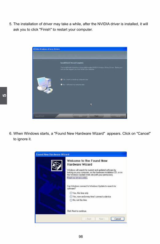
5
98
5. The installation of driver may take a while, after the NVIDIA driver is installed, it will ask you to click "Finish" to restart your computer.
6. When Windows starts, a "Found New Hardware Wizard" appears. Click on "Cancel" to ignore it.
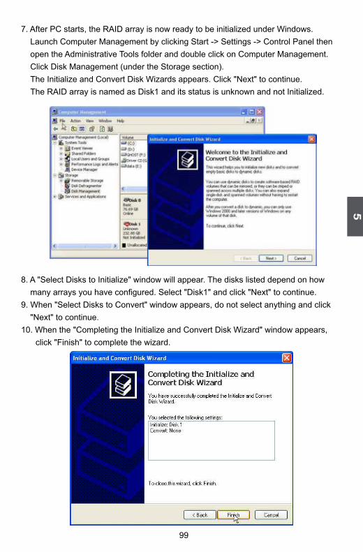
5
99
7. After PC starts, the RAID array is now ready to be initialized under Windows.Launch Computer Management by clicking Start -> Settings -> Control Panel thenopen the Administrative Tools folder and double click on Computer Management.Click Disk Management (under the Storage section).The Initialize and Convert Disk Wizards appears. Click "Next" to continue.The RAID array is named as Disk1 and its status is unknown and not Initialized.
8. A "Select Disks to Initialize" window will appear. The disks listed depend on how many arrays you have configured. Select "Disk1" and click "Next" to continue.
9. When "Select Disks to Convert" window appears, do not select anything and click "Next" to continue.
10. When the "Completing the Initialize and Convert Disk Wizard" window appears, click "Finish" to complete the wizard.
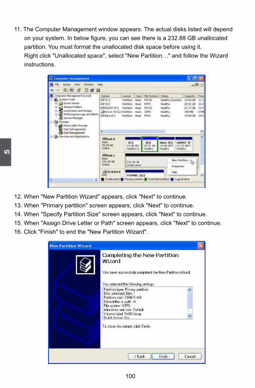
5
100
11. The Computer Management window appears. The actual disks listed will depend on your system. In below figure, you can see there is a 232.88 GB unallocated partition. You must format the unallocated disk space before using it.Right click "Unallocated space", select "New Partition…" and follow the Wizard instructions.
12. When "New Partition Wizard" appears, click "Next" to continue.13. When "Primary partition" screen appears, click "Next" to continue.14. When "Specify Partition Size" screen appears, click "Next" to continue.15. When "Assign Drive Letter or Path" screen appears, click "Next" to continue.16. Click "Finish" to end the "New Partition Wizard".

5
101
17. The format of disk array (Disk1) is in processing.
18. Format completed, now you can start using your RAID array.