Embed Size (px)
Citation preview

M68PRM{D)Nov., 1976
M6800PROGRAMMING
REFERENCE MANUAL
The information in this document has been carefully checkedand is believed to be entirely reliable. However, no responsibilityis assumed for inaccuracies. Furthermore, such information doesnot convey to the purchaser of the product described any licenseunder the patent rights of Motorola, Inco or others.
Motorola reserves the right to change specifications withoutnotice.
EXORciser, EXORdisk, and EXORtape are trademarks of Motorola Inc.
First EditionMotorola, Inc. 1976
"All Rights Reserved"

ii

TABLE OF CONTENTS
CHAPTER 1: INTRODUCTION 1-1
CHAPTER 2: HARDWARE DESCRiPTION 2-1
2.02.12.1.12.1.1.12.1.1.22.1.1.32.1.1.42.1.22.1.2.1
Introduction 2-1The Basic Microcomputer Components 2-1
A Minimum System 2-1MPU - Microprocessor Unit 2-2ROM - 1024 x 8-Bit Read Only Memory 2-4RAM - 128 x 8-Bit Static Random Access 2-4PIA - Peripheral Interface Adapter 2-4Expanding the Basic System 2-6ACIA - Asynchronous Communications Interface Adapter 2-6
CHAPTER 3: PROGRAMMING THE M6800 MiCROPROCESSOR 3-1
3.0 Machine Code 3-13.1 Stack and Stack Pointer 3-13.2 Saving MPU Status 3-33.3 Interrupt Pointers 3-43.3.1 Reset (or Power On) 3-43.3.2 Non-Maskable Interrupt - NMI 3-53.3.3 Software Interrupt - SWI 3-53.3.4 Interrupt Request 3-53.3.5 Wait Instruction - WAI 3-63.3.6 Manipulation of the Interrupt Mask Bit 3-63.3.7 Special Programming Requirements 3-73.3.8 Look-Ahead Feature 3-73.3.9 Return from Interrupt - RTI 3-73.4 Subroutine Linkage 3-83.4.1 Call Subroutine - BSR or JSR 3-83.4.2 Return from Subroutine - RTS 3-83.5 Data Storage in the Stack ~ 3-93.6 Reentrant Code 3-93.7 Manipulation of the Stack Pointer 3-9
CHAPTER 4: M6800 MICROPROCESSOR ADDRESSING MODES 4-1
4.0 Addressing Modes 4-14.1 Dual Addressing 4-14.2 Accumulator Addressing (Single Operand) 4-14.3 Inherent Addressing 4-14.4 Immediate Addressing 4-24.5 Relative Addressing 4-44.6 Indexed Addressing 4-44.7 Direct and Extended Addressing 4-6
iii

TABLE OF CONTENTS (Continued)
APPENDIX A: DEFINITION OF THE EXECUTABLE INSTRUCTIONS A-1APPENDIX B: EXbug AND MAID COMMANDS B-1APPENDIX C: MIKbug COMMANDS C-1APPENDIX 0: MINIbug II COMMANDS D-1APPENDIX E: MINlbug III COMMANDS E-1APPENDIX F: ASCII CODE CONVERSION TABLE F-1APPENDIX G: HEXADECIMAL AND DECIMAL CONVERSiON G-1
iv
CHAPTER 1INTRODUCTION
1.0 INTRODUCTION
Motorola Microsystem's software and development tools for the M68DO have been designed to simplify the implementation of systems using the M68DO Microcomputer Family. The M68DOProgramming Reference Manual is the basic software reference document to be used as a supplement to reference manuals for specific software products. It includes descriptions of:
• M6800 Program-visible Registers• Interrupts and Stack Operations• M6800 Addressing Modes• M6800 Instruction Set• Commands for
- EXbug- MIKbug- MINlbug II- MINlbug III
The manual also includes descriptions of basic M6800 Microcomputer Family components:
-MPU-ROM-RAM-PIA-ACIA
Available User's Guides and software reference manuals include:
• M68DD EXORciser User's Guide• EDOS II Operator's Manual• Co-Resident Assembler Reference Manual• Co-Resident Editor Reference Manual• Linking Loader Reference Manual• Macro Assembler Reference Manual• Resident FORTRAN Reference Manual• M68SAM Cross Assembler Reference Manual• M68EML Simulator Reference Manual• M68MPL Compiler Reference Manual
1-1

1-2

CHAPTER 2HARDWARE DESCRIPTION
2.0 INTRODUCTION
The MC6800 MPU is the nucleus of a series of fully bus-compatible, silicon gate NMOSbuilding blocks which are interconnected into the desired microcomputer system configuration.
Development tools are also available which emulate system function and performance sothat hardware may be evaluated and system software and firmware generated and debugged. Themost powerful is the M6800 EXORciser. By configuring its modules in his system's likeness, the userpossesses a surrogate prototype with which to edit, assemble and modify his programs in real time onthe actual hardware.
2.1 THE BASIC MICROCOMPUTER COMPONENTS
A minimum system can be assembled with four LSI (Large Scale Integration) bus orientedparts:
MPU - MicroprocessorRAM - 128 X 8 Random Access Memory
ROM - 1024 X 8 Read Only MemoryPIA - Peripherallnterface Module
2.1.1 A Minimum System
These parts can be interconnected without interface parts making a minimum functionalsystem (Figure 2-1). Such a system can easily be adapted for a number of small scale applications bysimply changing the application program content of the ROM.
~To
Peripheral"B"
~To
Peripheral"A"PAe·PA7
E RES
CAl
CA2
RSG!I·RSI
CS4>CSl
CS2RIW
PBG!I·PB7RIW
!lAMAG!I·A6
09·07
A13
A2
A0-AI
A14
A0·A6
A0·A9
L-..---~E
'-----E'-------elE
Data Bus 00· 07
VMAe02
+5.0 v _H
FIGURE 2-1. Minimum System Configuration
2-1

The minimum system may be exp"anded without the addition of TIL integrated circuitsproviding the load does not exceed the capacity ofthe MPU. The MPU has capacity to drive a 'oad ofone standard TIL input and 130 picofarads at one megahertz.
2.1.1.1 MPU - Microprocessing Unit
Some of the more important features of the MC6800 Microprocessing Unit that contributeto the "ease of use" in a system are:
• Eight-bit parallel processing• Bi-directional data bus• Sixteen-bit address bus - 65k bytes of addressing.72 instructions - variable length• Seven addressing modes - Direct, Relative, Immediate, Indexed, Extended, Implied,
and Accumulator• Interrupt vectoring• Two Accumulators• Index Register• Program Counter• Stack Pointer and variable length stack• Condition Code Register (6 codes)• Separate Non-Maskable Interrupt• Direct Memory Access (DMA) and multiple processor capability• Clock operating rates up to 1 MHz• Simple interface without TIL• Halt/ Go. and single instruction execution capability.40 pin packageA programming model of the microprocessing unit is represented in Figure 2-2. This
comprises all of the registers in the MPU which are controlled explicitly by programs. The inputs andoutputs of the MPU form five functional groups (see Figure 2-3):
1. 8-bit data bus2. 16-bit address bus3. Controls4. Clock input signals5. Power supply and groundThis manual, being concerned with the programming of the MPU, primarily considers the
information being transferred on the data bus and the address bus connected to the MPU.In this manual, the control signals are considered only as they affect execution of a
program. The control signals are as follows:
• Reset• Halt• Non-Maskable Interrupt• Interrupt Request• Read/ Write• Data Bus Enable• Valid Memory Address• Three-state Control• Bus AvailableReset, Halt, Non-Maskable Interrupt, and Interrupt Request are considered in Chapter 3.
Read/ Write, Data Bus Enable, and Valid Memory Address are considered only as they relate to the
2-2

=-- JAceumu'.'o. A
o
7
I ACCA
7
I ACCB
IX
PC
SPI IStack Pointer
Condition Codes.............---L..r"""""r........,.......,.......,... Register
Carry-Borrow
Overflow (Two's Complement)
Zero
~-- Negative
"----- Interrupt Mask
1------ Half Carry (From Bit 3)
FIGURE 2-2. Programming Model of the M6800 Microprocessor
a·Bit Data Bus )
16-Bit Address Bus )
Controls ) M6800 Microprocessor--------...."Clock Input Signals )
Power Supply and GrOund)
FIGURE 2-3. M6800 Microprocessor - Inputs and Outputs
addressing of the memory and interlace units. Three-State Control, Bus Available, and the Halt controllines function in Direct Memory Access (DMA) and mUltiple processor operations.
The execution time of any instruction in a program is directly proportional to the clockperiod and is, therefore, expressed as a number of clock cycles. Apart from the times of execution ofinstructions, the clock inputs are not otherwise considered in this manual.
The information contained in this programming manual applies to programs written forexecution by the microprocessing unit, and is not restricted to any particular set of parts with which theMPU may be interconnected in any system. Motorola offers a family of parts that are compatible withthe MPU and which may be easily assembled into a computing system giving the user the most costeffective solution to his problem.
2-3

2.1.1.2 ROM - 1024 X B-Bit Read Only Memory
The MCM6830 is a mask-programmable byte-organized memory designed for use inbus-organized systems. It is fabricated with N-channel silicon-gate technology. The ROM operatesfrom a single power supply, is compatible with TTL and DTL, and needs no clocks or refreshing
because of static operation.The memory is compatible with the M6800 Microcomputer Family, providing read only
storage in byte increments. Memory expansion is provided through multiple chip select inputs. Theactive level of the chip select inputs and the memory content are defined by the customer. Some of the
important features of the ROM are:• Organized as 1024 bytes (1 byte = 8 bits)• Static operation• Three-state data output• Four chip select inputs (mask option)• Single 5 volt power supply• TTL/ DTL compatible• Maximum access time = 575 ns
2.1.1.3 RAM - 12B X B-Bit Static. Random Access Memory
The MCM6810 is a byte-organized memory designed for use in bus-organized systems. Itis fabricated with N-channel silicon-gate technology. The RAM operates from a single power supply,has compatibility with TTL and DTL, and needs no clocks or refreshing because of static operation.
The memory is compatible with the M6800 Microcomputer Family, providing randomstorage in byte increments. Memory expansion is provided through multiple chip select inputs. Someof the important features of the RAM are:
• Organized as 128 bytes (1 byte = 8 bits)• Static operation• Bi-directional, three-state, data input/ output• Six chip select inputs (four active low, two active high)• Single 5-volt power supply• TTL/ DTL compatible• Maximum access time = 1.0 us for MCM6810L
575 ns for MCM6810L-1
2.1.1.4 PIA - Peripheral Interface Adapter
The MC6820 Peripheral Interface Adapter provides an effective means of interfacingperipheral equipment to the MC6800 Microprocessing Unit (MPU). This device is capable of interfacing the MPU to peripherals through two, 8-bit, bi-directional, peripheral data buses and four controllines. No external logic is required for interfacing to most peripheral devices.
The functional configuration ofthe PIA is programmed by the MPU during system initialization. Each of the peripheral data lines can be programmed to act as an input or output, and each of thefour controll interrupt lines may be programmed for one of several control modes, as shown in Figure2-4. This allows a high degree of flexibility in the over-all operation of the interface. Some of theimportant features of the PIA are:
• An 8-bit bi-directional data bus for communication with the MPU• Two bi-directional 8-bit buses for interface to peripherals• Two programmable control registers
2-4
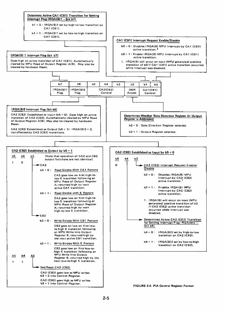
Determine Active CA1 (CB1) Transition for SettingInterrupt Flag IROA(B)1 -(bit b7)
bl :::: 0: I ROA(B)l set by high-to-Iow transition onCAl (CB1).
bl :::: 1 : I ROA(B) 1 set by low-to-high transition onCAl (CB1).
I
IROA(B) 1 Interrupt Flag (bit b7)
Goes high on active transition of CAl (CB1); Automaticallycleared by MPU Read of Output Register A(B). May also becleared by hardware Reset.
CA1 (Cal) Interrupt Request Enable/Disable
bO:::: 0: Disables IROA(B) MPU Interrupt by CAl (CB1)active transition. 1
bO:::: 1 : Enable I ROA(B) MPU Interrupt by CAl (CB1)active transition.
1. I ROA(B) will occur on next (MPU generated) positivetransition of bO if CA 1 (CB1) active transition occurredwhile interrupt was disabled.
I
b7
IROA(B)lFlag
I
b6
IROA(B)2Flag
I
b5 b4 I b3
CA2(CB2)Control
b2
DDRAccess
I
bl 1 b4>
CA1(CB1)Control
IRQA(B)2 Interrupt Flag (bit b6)
CA2 (CB2) Established as Input (b5 :::: 0): Goes high on activetransition of CA2 (CB2); Automatically cleared by MPU Readof Output Register A(B). May also be cleared by hardwareReset.
CA2 (CB2) Established as Output (b5 :::: 1): I ROA(B)2 '" O.not affected by CA2 (CB2) transitions.
r
Determines Whether Data Direction Register Or OutputRegister IS Addressed
b2 '" 0 : Data Direction Register selected.
b2:::: 1 : Output Register selected.
ICA2 (CB2) Established as Input by b5:::: 0
'-----..-- Determines Active CA2 (CB2) Transitionfor Setting Interrupt Flag I ROA(B)2 (bit b6)
CA2 (Ca2) Established as Output by b5 =1
b5 b4 E~ (Note that operation of CA2 and CB2output functions are not identical)
1 0~CA2
b3 '" 0 : Read Strobe With CA 1 Restore
CA2 goes low on first high-tolow E transition following anMPU Read of Output RegisterA; returned high by nextactive CA 1 transition.
b3 '" 1: Read Strobe with E Restore
CA2 goes Iowan first high-tolow E transition following anMPU Read of Output RegisterA; returned high by nexthigh-to-Iow E transition.
~CB2
b3 '" 0: Write Strobe With CBl Restore
CB2 goes on low on first lowto high E transition followingan MPU Write into OutputRegister B; returned high bythe next active CBl transition.
b3 '" 1: Write Strobe With E Restore
CB2 goes low on first low-tohigh E transition following an
b3 MPU Write into Output
lRegister B; returned high by thenext low-to-high E transition.
Set/Reset CA2 (CB2)
CA2 (CB2) goes low as MPU writesb3'" 0 Into Control Register.
CA2 (CB2) goes high as MPU writesb3 '" 1 into Control Register.
2-5
b5
o
b4-,-
b3
L. CA2 (CB2) Interrupt Request EnablelDisable
b3:::: 0: Disables IRQA(B) MPUInterrupt by CA2 (CB2)active transitlon. l
b3'" 1: Enables I ROA(B) MPUInterrupt by CA2 (CB2)active transition.
1. I ROA(B) will occur on next (MPUgenerated) positive transition of b3if CA2 (CB2) active transitionoccurred while interrupt wasdisabled.
b4 :::: 0: I ROA(B)2 set by high-to-Iowtransition on CA2 (CB2).
b4'" 1: I ROA(B)2 set by low-to-hightransition on CA2 (CB2).
FIGURE 2-4. PIA Control Register Format

Controls
B·Bit Data Bus
Controls
MPU = Microprocessing UnitROM = Read-Only MemoryRAM = Random Access MemoryPIA =Peripheral Interface AdapterACIA = Asynchronous Communications Interface Adapter(MODEM = Modulator/Demodulator)
Peripheral Devices
FIGURE 2·5. Expanded M6800 Microcomputer
• Two programmable data direction registers• Four individually controlled interrupt input lines; Two usable as peripheral control out-
puts• Handshake control logic for input and output peripheral operation• High-impedance three-state and direct transistor drive peripheral lines• Program controlled interrupt and interrupt disable capability• CMOS compatible peripheral lines
2.1.2 Expanding the Basic System
The minimum system can be expanded with other family parts to meet the needs of morecomplex systems (see Figure 2-5). Motorola also is continually developing new parts to add to thefamily.
2.1.2.1 ACIA - Asynchronous Communications Interface Adapter
The MC6850 Asynchronous Communications Interface Adapter provides the data formatting and control to interface serial asynchronous data communications information to bus organizedsystems such as the MC6BOO Microprocessing Unit.
The bus interface of the MC6850 includes select, enable, read/ write, interrupt and businterface logic to allow data transfer over an 8-bit bi-directional data bus. The parallel data of the bussystem is serially transmitted and received by the asynchronous data interface, with proper formattingand error checking. The functional configuration of the ACIA is programmed via the data bus duringsystem initialization. A programmable control register provides variable word lengths, clock divisionratios, transmit control, receive control, and interrupt control (see Figures 2-6 and 2-7). For peripheralor modem operation, three control lines are provided. These lines allow the ACIA to interface directlywith the MC6860L 0-600 bps Digital Modem. Some of the features of the ACIA are:
• Eight and nine-bit transmission
2-6
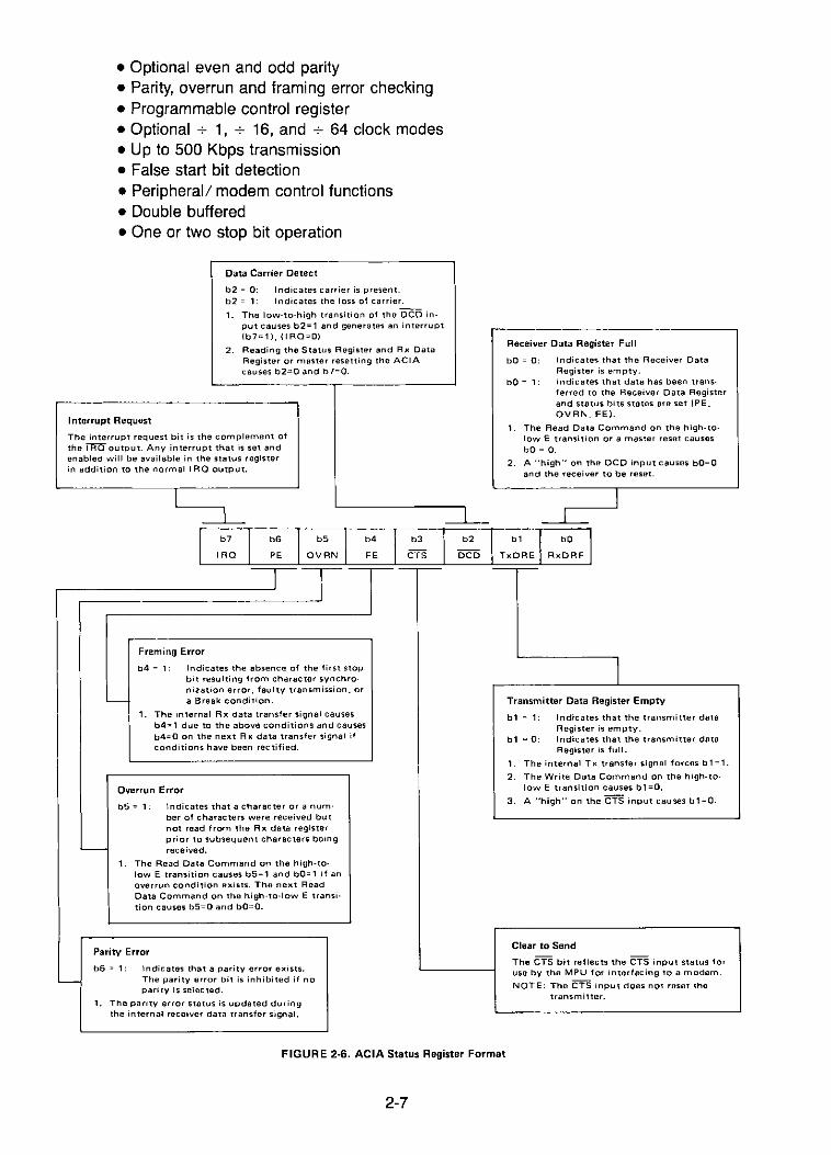
• Optional even and odd parity• Parity, overrun and framing error checking• Programmable control register• Optional -:- 1, -:- 16, and -:- 64 clock modes• Up to 500 Kbps transmission• False start bit detection• Peripheral! modem control functions• Double buffered• One or two stop bit operation
Data Carrier Detect
b2 = 0: Indicates carrier is present.b2 = 1: Indicates the loss of carrier.
1. The low-to-high transition of the DCD input causes b2=1 and generates an interruptIb7=1l. II RQ=OI
2. Reading the Status Register and Rx DataRegister or master resetting the ACIAcauses b2=O and b7=0.
Interrupt Request
The interrupt request bit is the complement ofthe I RQ output. Any interrupt that is set andenabled will be available in the status registerin addition to the normal I RQ output.
Receiver Data Register Full
bO = 0: Indicates that the Receiver DataRegister is emptY.
bO = 1: Indicates that data has been transferred to the Receiver Data Registerand status bits states are set IPE.OVRN. FE).
1. The Read Data Command on the high-tolow E transition or a master reset causesbO = O.
2. A "high" on the DCD input causes bO=Oand the receiver to be reset.
I
I1
b7 IIRQ
Ib6
b5 I b4 I b3 I b2
PE OVRN FE CTS DCD
I T
J
r
Framing Error
b4 = 1: Indicates the absence of the first stopbit resulting from character synchro·nization error. faultY transmission. or
L.....- a Break condition.
1. The internal Rx data transfer signal causesb4=1 due to the above conditions and causesb4=O on the next R x data transfer signal ifconditions have been rectified.
Overrun Error
b5 = 1: Indicates that a character or a number of characters were received butnot read from the Rx data registerprior to subsequent characters being
'--- received.
1. The Read Data Command on the high-tolow E transition causes b5= 1 and bO= 1 if anoverrun condition exists. The next ReadData Command on the high-to-Iow E transition causes b5=0 and bO=O.
Parity Error
b6 = 1: Indicates that a parity error exists.'-- The paritY error bit is inhibited if no
pari ty is selec ted.
1. The parity error status is updated duringthe internal receiver data transfer signal.
FIGURE 2-6. ACIA Status Register Format
2-7
ITransmitter Data Register Empty
b1 = 1: I ndicates that the transmitter dataRegister is empty.
b1 = 0: Indicates that the transmitter dataRegister is full.
1. The internal T x transfer si gnal forces b 1= 1.
2. The Write Data Command on the high-tolow E transition causes b1=0.
3. A "high" on the CTS input causes b1=0.
Clear to Send
The CTS bit reflects the CTS input status foruse by the MPU for interfacing to a modem.
NOTE: The CTS input does not reset thetransmitter.

Enable for Receiver Inte"upt
b7:::: 1: Enables Interrupt Output inAecelving Mode
b7:::: 0: Disables Interrupt Output inAecelving Mode
Counter ratio and Master reset select usedin both transmitters and receiver sections
b1 bO Function (Tx, Ax)
0 0 +1
0 1 +16
1 0 +64
1 1 MASTE A AESET
~b7 b6 b5 b4 b3 b2 b1 bO
AlE TC2 TC1 WS3 WS2 WS1 CDS2 CDS1
II
Word Length, Parity, and Stop Bit Select
Transmitter Control Bits: Controls the Interrupt Output" and RTS b4 b3 b2 Word Length + Parity + Stop BitsOutput, and provides for Transmission of a Break 0 0 0 7 Even 2
b6 b5 Function 0 0 1 7 Odd 2
0 0 Sets ATS :::: 0 and Inhibits Tx interrupt (TIE) 0 1 0 7 Even 1
0 1 Sets RTS::: 0 and enables Tx interrupt (TIE) 0 1 1 7 Odd 1
1 0 Sets RTS ::: 1 and Inhibits Tx interrupt (TI E) 1 0 0 8 None 2
1 1 Sets RTS ::: O. Transmits Break and inhibits Tx 1 0 1 8 None 1interrupt (TI E) 1 1 0 8 Even 1
·TI E is the enable for the interrupt output in transmit mode. 1 1 1 8 Odd 1
FIGURE 2-7. ACIA Control Register Format
2-8
CHAPTER 3PROGRAMMING THE M6800 MICROPROCESSOR
3.0 MACHINE CODE
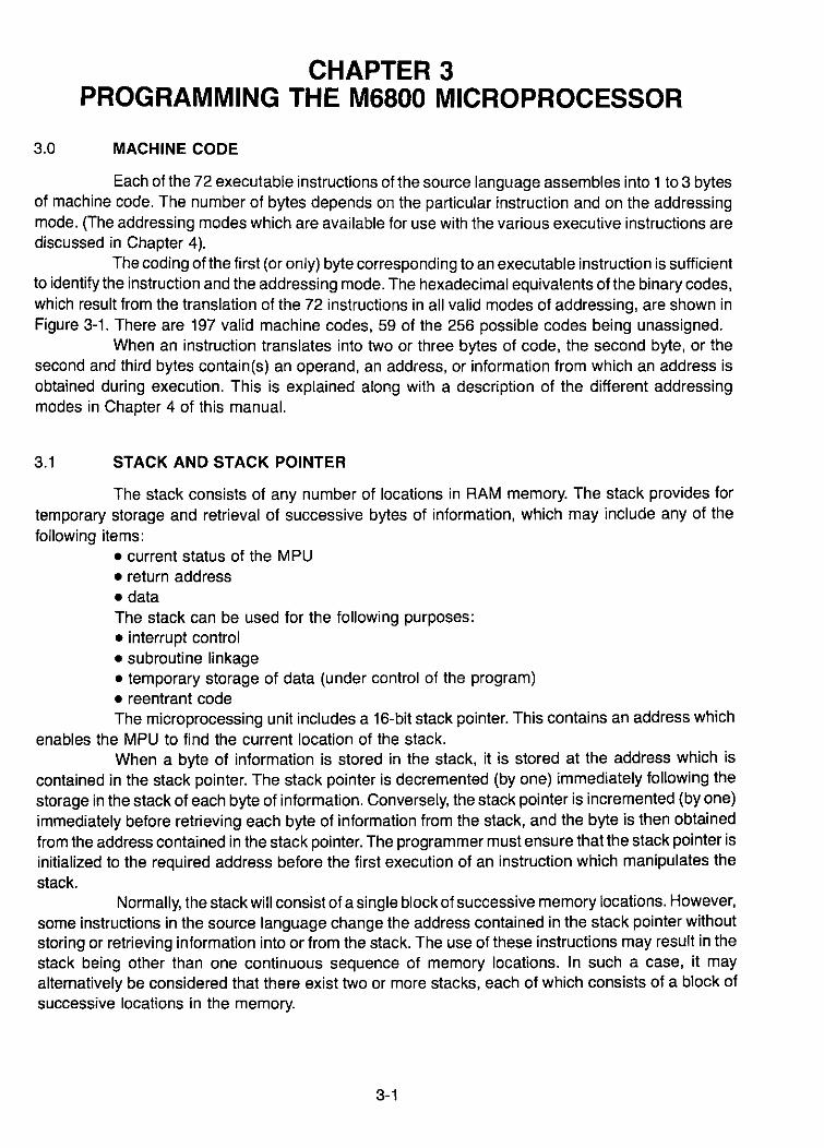
Each of the 72 executable instructions of the source language assembles into 1 to 3 bytesof machine code. The number of bytes depends on the particular instruction and on the addressingmode. (The addressing modes which are available for use with the various executive instructions arediscussed in Chapter 4).
The coding of the first (or only) byte corresponding to an executable instruction is sufficientto identify the instruction and the addressing mode. The hexadecimal equivalents of the binary codes,which result from the translation of the 72 instructions in all valid modes of addressing, are shown inFigure 3-1. There are 197 valid machine codes, 59 of the 256 possible codes being unassigned.
When an instruction translates into two or three bytes of code, the second byte, or thesecond and third bytes contain(s) an operand, an address, or information from which an address isobtained during execution. This is explained along with a description of the different addressingmodes in Chapter 4 of this manual.
3.1 STACK AND STACK POINTER
The stack consists of any number of locations in RAM memory. The stack provides fortemporary storage and retrieval of successive bytes of information, which may include any of thefollowing items:
• current status of the MPU• return address
• dataThe stack can be used for the following purposes:• interrupt control• subroutine linkage• temporary storage of data (under control of the program)• reentrant codeThe microprocessing unit includes a 16-bit stack pointer. This contains an address which
enables the MPU to find the current location of the stack.When a byte of information is stored in the stack, it is stored at the address which is
contained in the stack pointer. The stack pointer is decremented (by one) immediately following thestorage in the stack of each byte of information. Conversely, the stack pointer is incremented (by one)immediately before retrieving each byte of information from the stack, and the byte is then obtainedfrom the address contained in the stack pointer. The programmer must ensure that the stack pointer isinitialized to the required address before the first execution of an instruction which manipulates thestack.
Normally, the stack will consist of a single block of successive memory locations. However,some instructions in the source language change the address contained in the stack pointer withoutstoring or retrieving information into or from the stack. The use of these instructions may result in thestack being other than one continuous sequence of memory locations. In such a case, it mayalternatively be considered that there exist two or more stacks, each of which consists of a block ofsuccessive locations in the memory.
3-1

00 * 40 NEG A 80 SUB A IMM CO SUB B IMM01 NOP 41 * 81 CMP A IMM C1 CMP B 'MM02 * 42 * 82 SBC A IMM C2 SBC B IMM03 * 43 COM A 83 * C3 *04 * 44 LSR A 84 AND A IMM C4 AND B IMM05 * 45 * 85 BIT A IMM C5 BIT B IMM06 TAP 46 ROR A 86 LOA A IMM C6 LOA B IMM07 TPA 47 ASR A 87 * C7 *08 INX 48 ASL A 88 EOR A IMM C8 EOR B IMM09 OEX 49 ROL A 89 AOC A IMM C9 AOC B IMMOA CLV 4A DEC A 8A ORA A IMM CA ORA B rMMOB SEV 4B * 8B ADD A IMM CB ADD B IMMOC CLC 4C INC A 8C CPX A IMM CC *00 SEC 40 TST A 80 BSR REL CD *OE CLI 4E * 8E LOS IMM CE LOX rMMOF SEI 4F CLR A 8F · CF ·10 SBA 50 NEG B 90 SUB A OIR DO SUB B orR11 CBA 51 · 91 CMP A OIR 01 CMP B OIR12 · 52 · 92 SBC A OIR 02 SBC B orR13 · 53 COM B 93 · 03 ·14 * 54 LSR B 94 AND A OIR 04 AND B OIR15 · 55 * 95 BIT A OIR 05 BIT B OIR16 TAB 56 ROR B 96 LOA A OIR 06 LOA B OIR17 TBA 57 ASR B 97 STA A OIR 07 STA B OIR18 · 58 ASL B 98 EOR A orR 08 EOR B orR19 ·OAA 59 ROL B 99 AOC A OIR 09 AOC B OIR1A · SA DEC B 9A ORA A OIR OA ORA B OIR1B ABA 5B · 9B ADD A orR DB ADD B orR1C * 5C INC B 9C CPX OIR DC ·10 · 50 TST B 90 * DO ·1E · 5E · 9E LOS OIR DE LOX OIR,1F * SF CLR B 9F STS OIR OF STX orR20 BRA REL 60 NEG INO AO SUB A INO EO SUB B INO21 * 61 * A1 CMP A rNO E1 CMP B rNO22 BHI REL 62 · A2 SBC A INO E2 SBC B INO23 BLS REL 63 COM INO A3 · E3 ·24 BCC REL 64 LSR INO A4 AND A INO E4 AND B INO25 BCS REL 65 · AS BIT A INO E5 BIT B INO26 BNE REL 66 ROR INO A6 LOA A INO E6 LOA B INO27 BEQ REL 67 ASR INO A7 STA A INO E7 STA B INO28 BVC REL 68 ASL INO A8 EOR A INO E8 EOR B rNO29 BVS REL 69 ROL INO A9 AOC A INO E9 AOC B INO2A BPL REL 6A DEC INO AA ORA A INO EA ORA B INO2B BMI REL 6B · AB ADD A INO EB ADD B INO2C BGE REL 6C INC INO AC CPX INO EC *20 BLT REL 60 TST INO AD JSR INO ED *2E BGT REL 6E JMP INO AE LOS INO EE LOX INO2F BLE REL 6F CLR INO AF STS INO EF STX INO30 TSX 70 NEG EXT BO SUB A EXT FO SUB B EXT31 INS 71 * B1 CMP A EXT F1 CMP B EXT32 PUL A 72 * B2 SBC A EXT F2 SBC B EXT33 PUL B 73 COM EXT B3 * F3 *34 DES 74 LSR EXT B4 AND A EXT F4 AND B EXT35 TXS 75 * B5 BIT A EXT F5 BIT B EXT36 PSH A 76 ROR EXT B6 LOA A EXT F6 LOA B EXT37 PSH B n ASR EXT B7 STA A EXT F7 STA B EXT38 * 78 ASL EXT B8 EOR A EXT F8 AOC B EXT39 RTS 79 ROL EXT B9 AOC A EXT F9 AOC B EXT3A * 7A DEC EXT BA ORA A EXT FA ORA B EXT3B RTI 7B · BB ADD A EXT FB ADD B EXT3C * 7C INC EXT BC CPX EXT FC *3D · 70 TST EXT BO JSR EXT FO ·3E WAI 7E JMP EXT BE LOS EXT FE LOX EXT3F SWI 7F CLR EXT BF STS EXT FF STX EXT
Notes: 1. Addressing Modes: A :;:: Accumulator AB :;:: Accumulator BREL :;:: RelativeINO :;:: Indexed
2. Unassigned. code indicated by"·".
IMM :;:: ImmediateOIR :;:: Direct
TABLE 3·1. Hexadecimal Values of Machine Codes
3-2

3.2 SAVING MPU STATUS
The status of the microprocessing unit is saved in the stack during the following opera-tions:
SP
~
-CC
ACCB
ACCA
IXH
IXl
PCH
PC'l
m + 1
m + 2
m
m - 1
m - 9
m - 8
m - 7
m - 6
m- 5
m-4
m - 3
m - 2
SP
l
~
.. -
~
u
V-ell
iii
m + 1
m
m + 2
m - 2
m -1
• in response to an external condition indicated by a negative edge on the Non-MaskableInterrupt control input signal to the MPU.
• during execution of the machine code corresponding to either of the source languageinstructions SWI (Software Interrupt) or WAI (Wait for Interrupt).
• during servicing of an interrupt from a peripheral device, in response to a negative edgeon the Interrupt Request control input signal to the MPU and provided the interrupt maskbit (I) is clear.
The status is stored in the stack in accordance with the scheme shown in Figure 3-2.Before storing the status, the stack pointer contains the address of a memory location represented inFigure 3-2 by "m." The stack, if any, extends from location "m + 1" to higher locations. The status isstored in seven bytes of memory, beginning with the byte at location "m," and ending with the byte atlocation lim - 6." The stack pointer is decremented after each byte of information is entered into thestack.
The information which is saved in the stack consists of the numerical content of all of theregisters of the programming model, shown in Figure 2-2, except the stack pointer.
The value stored for the program counter (PCH and PCl) is in accordance with thefollowing rules:
1. In response toa Non-Maskable Interrupt or to an interrupt from a peripheral device, thevalue saved for the program counter is the address of that instruction which would nextbe executed, if the interrupt had not occurred.
2. During execution of a SWI or WAI instruction, the value saved for the program counter isthe address of that SWI or WAI instruction, pius one.
I II
Before After
SP = Stack Pointer
CC = Condition Codes (Also called the Processor Status Byte)ACC B = Accumu lator B
ACCA = Accumulator A
I X H = I ndex Register, Higher Order 8 Bits
I Xl = Index Register, lower Order 8 BitsPC H = Program Counter, Higher Order 8 BitsPCl = Program Counter, Lower Order 8 Bits
FIGURE 3-2. Saving the Status of the Microprocessor in the Stack
3-3

The values stored for the other registers (CC, ACCS, ACCA, IXH and IXL) are in accordance with the following rules:
1. In response to a Non-Maskable Interrupt, or an interrupt from a peripheral device, thevalues saved are those which resulted from the last instruction executed before theinterrupt was serviced.
2. During execution of a SWI or WAI instruction, the values saved are those which resultedfrom the last instruction executed before the SWI or WAI instruction.
3. The condition codes H, I, N, Z, V, and C, in bit positions 5 thru 0 of the processorcondition code register, are stored respectively in bit positions 5 thru 0 of the applicablememory location in the stack. Bit positions 7 and 6 of that memory location are set (go tothe 1 state).
3.3 INTERRUPT POINTERS
A block of memory is reserved for pointers, which provide for read-only storage of theaddresses of programs which are to be executed in the event of a reset (or power on), a low state of theNon-Maskable Interrupt control input, a software interrupt, or a response to an interrupt signal from aperipheral device. The respective pointers each occupy two bytes of memory and are disposed atlocations from "n - 7" to "n," as indicated in Figure 3-3.
The location indicated in Figure 3-3 by "n" is that location which is addressed when all thelines of the address bus are in the high ("1 ") state. In most systems, the location "n" will be the highestaddress in the memory. However, the correspondence of "n" to a particular numerical value dependson the hardwired interconnections of the parts of the programmable system to the address bus.
3.3.1 Reset (or Power On)
The Reset control input to the MPU is used to start the execution of the program, either forinitial start-up or from a power down condition following a power failure. When a positive edge isdetected on this input line, the program counter is loaded with the address stored in the restart pointerat locations "n - 1" and "n" of memory (see Figure 3-3). The MPU then proceeds with execution of aRestart Program, which begins with the instruction addressed by the program counter. The restart andthe continued execution, however, depends on the Gol Halt control input being in the "Go" condition.
When the Gol Halt control input is in the high state, the machine will fetch the instructionaddressed by the program counter and start execution. When this line changes to a low, execution will
Internal Interrupt Pointer-- {
J----t
Software Interrupt Pointer -- {
J----t
Non-Maskable Interrupt Pointer - {
J----t
Reset Pointer {
~--
n-7
n-6
n-5
n-4
n-3
n-2
n-1
n
n = Memory Location Addressed When All Lines of
The Address Bus are in the High (1) State.
FIGURE 3·3. Reset and Interrupt Pointers
3-4

stop. The stop may become effective at the completion of execution of the current instruction.Alternatively, one more instruction may be executed before the stop becomes effective, due to thelook-ahead capability described in Section 3.3.8. Execution of the program will not be resumed untilthe "Go" condition is restored.
TheGo/ Halt input must remain in the "Go" condition for the interrupt sequences to becompleted. Otherwise, the machine will stop execution at the end of an instruction. The followingsections of this manual, which describe the interrupt operations, assume that the "Go" state ismaintained.
3.3.2 NMI - Non-Maskable Interrupt
The sequence of operations, which occurs following a non-maskable interrupt, is initiatedby a neg~tive edge on the Non-Maskable Interrupt control input to the MPU. Execution of the currentinstruction is completed. The response of the MPU to the Non-Maskable Interrupt signal may begin onthe completion of execution of the current instruction. Alternatively, one or more instructions in theprogram may first be executed, due to the look-ahead capability of the MPU described in Section3.3.8.
The status of the MPU is then saved in the stack, as described in Section 3.2 and theprogram counter is loaded with the address stored in the Non-Maskable Interrupt pointer at locations"n - 3" and "n - 2" of memory (see Figure 3-3). The MPU then starts execution of the Non-MaskableInterrupt Program, which begins with the instruction which is now addressed by the program counter..
3.3.3 SWI - Software Interrupt
During execution of the SWI instruction, the status of the MPU is saved in the stack, asdescribed in Section 3.2. The value saved for the program counter is the address of the SWIinstruction, plus one.
After the status has been saved, the interrupt mask bit "I" is set (I = 1). The MPU will notrespond to an interrupt request from a peripheral device while the interrupt mask bit is set.
The program counter is then loaded with the address stored in the software interruptpointer at locations "n - 5" and "n - 4" of memory (see Figure 3-3). The MPU then proceeds withexecution of a Software Interrupt Program, which begins with the instruction whose address is now inthe program counter.
The MPU will remain insensitive to an interrupt request from any peripheral device(signalled by a "low" state of the Interrupt Request control input signal to the MPU) until the interruptmask bit has been reset by execution of the programmed instructions.
3.3.4 IRQ - Interrupt Request
A request for an interrupt by a peripheral device is signalled by a low state of the InterruptRequest control input to the MPU (IRQ).
The MPU will not respond to an Interrupt Request while the interrupt mask bit is set (I = 1).Normal execution of the program continues until the interrupt mask bit is reset (I = O)enabling the MPUto respond to the Interrupt Request.
Execution of the current instruction will always be completed before the MPU responds toan Interrupt Request. The response of the MPU to the Interrupt Request may begin on the completionof the current instruction. Alternatively, one more instruction in the program may first be executed, due
3-5

to the look-ahead capability of the MPU described in Section 3.3.8. The Response of the MPU to theInterrupt Request then proceeds as follows:
1. Saving the StatusProvided the last instruction executed was not a WAI instruction, the status of the MPU;s saved in the stack, as described in Section 3.2. The value saved for the programcounter is the address of the instruction which would be the next to be executed if theinterrupt had not occurred. If the last instruction executed was a WAI instruction, theaddress of the next instruction is not saved since PC and MPU status were alreadysaved by the WAI instruction in preparation for an interrupt.
2. Interrupt MaskThe interrupt mask bit is then set (I = 1). This prevents the MPU from responding tofurther interrupt requests until the interrupt mask bit has been cleared by execution ofprogrammed instructions.
3. Internal Interrupt Pointer and ProgramThe program counter is loaded with the address stored in the internal interrupt pointer atlocations lin - 7" and lin - 6" of memory (see Figure 3-3). The MPU then proceeds withexecution of an internal interrupt program, which begins with the instruction currentlybeing addressed by the program counter. The internal interrupt pointer is selected bylogic which is internal to the MPU. At the point when execution of the internal interruptprogram begins, no distinction will have been made regarding the source ofthe interruptrequest. In a system in which there is more than one possible source of interruptrequest, the internal interrupt program must include a routine for identifying the origin ofthe request. In a system composed of the Motorola Microcomputer Kit, this routinewould consist of a programmed interrogation of the addressable registers of the PIAsand ACIAs, in order to identify the peripheral device which has requested the interrupt.
3.3.5 WAI - Wait Instruction
During execution of the WAI instruction, the status of the MPU is saved in the stack, asdescribed in Section 3.2. The value saved for the program counter is the address of the WAIinstruction, plus one.
Execution of the WAI instruction does not change the interrupt mask bit.If the interrupt mask bit is set (I = 1), the MPU cannot respond to an interrupt request from
any peripheral device. Execution stops after MPU status is saved and can be resumed only via aNon-Maskable Interrupt or a reset interrupt.
If the interrupt mask bit is in the reset state (I = 0), the MPU will service any interruptrequest which may be present. If the Interrupt Request input is in the high state, execution will besuspended, and the MPU will wait for an Interrupt Request to be signalled. If an Interrupt Request issignalled by the Interrupt Request input changing to the low state, the interrupt will be serviced aspreviously described: the interrupt mask bit will be set, the program counter will be loaded with theaddress stored in the internal interrupt pointer, and execution of the internal interrupt program willbegin.
3.3.6 Manipulation of the Interrupt Mask Bit
The interrupt mask bit is affected by execution of the source language instructions SWIand RTI, and by the servicing of an interrupt request from a peripheral device, as has been previously
3-6

described. The interrupt mask may also be manipulated by the use of any of the following instructions:• CLI - clear interrupt mask bit• SEI - set interrupt mask bit• TAP - transfer accumulator A to processor condition codes register
The state of the interrupt mask bit can also be affected as a result of the following instruction:• TPA - transfer the processor condition codes register to accumulator A.During execution of the TPA instruction, the condition codes H, I, N, Z, V, and C, in bit
positions 5 thru 0 of the processor condition codes register are stored respectively in bit positions 5thru 0 of accumulator A. Bit positions 7 and 6 of accumulator A are set (Le. go to the 1 state). Afterexecution of the TAP instruction, the state of each of the condition codes (H, I, N, Z, V, C) will bewhatever is retrieved from the respective bit positions (5 thru 0) of accumulator A.
3.3.7 Special Programming Requirements
A comprehensive program should make provision for the following special requirements:(a) Pointers:
The program should place the addresses of the reset .and interrupt routine in therespective pointers (see Figure 3-3) at the high-address end of memory. The addresses would usually be placed in the pointers by use of the FOB assembler directive in thesource program.
(b) Reset and Interrupt Sequences:The sequences of instructions to be addressed by the Reset pointer, the NonMaskable Interrupt pointer, the Software Interrupt pointer, and the Internal Interruptpointer, should be provided in the program.
(c) Input and Output:The program would normally include provisions for inputs and outputs relating toperipheral devices. In a programmable system composed of the parts of the MotorolaMicrocomputer Family, the input and output routines would involve reading and writingcoded data from and into the addressable registers of the PIAs and ACIAs. The inputand output routines would normally be reached via conditional branch instructions inthe Internal Interrupt Program.
3.3.8 Look-Ahead Feature
The MPU responds, at the completion of the instruction being executed, to any of thefollowing signals:
• Halt• Non-Maskable Interrupt• Interrupt Request (when the interrupt mask is in the reset state).However, if the interrupt occurs during the last cycle of an instruction, the look-ahead to the
next instruction feature will mask the interrupt until the completion of the next instruction.
3.3.9 RTI - Return from Interrupt
The source language instruction RTI assembles into one byte of the machine code.Execution of this instruction consists of the restoration of the MPU to a state pulled from the stack.
The information which is obtained from the stack provides for the numerical content of theregisters of the programming model shown in Figure 2-2. The operation is the reverse of thatrepresented in Figure 3-2. Seven bytes of information are pulled from the stack and stored in
3-7

respective registers of the MPU. The address stored in the stack pointer is incremented before eachbyte of information is pulled from the stack.
After execution of the RTI instruction, the state of each of the condition codes (H, I, N, Z, V,and C) will be whatever is retrieved from the respective bit positions (5 thru 0) of the applicablememory location in the stack. In particular, it should be noted that the interrupt mask bit (I-bit) may beeither set or reset by execution of the RTI instruction.
3.4 SUBROUTINE LINKAGE
The stack provides an orderly method of calling a subroutine and returning from thesUbroutine. Use of a stack allows subroutine calls when in a subroutine (subroutine nesting).
3.4.1 Call Subroutine (BSR o"r JSR)
A return address is saved in the stack during execution ofthe machine code correspondingto either of the source language instructions BSR (branch to subroutine) or JSR uump to subroutine).
The return address is stored in the stack in accordance with the scheme shown in Figure3-4. Before storing the return address, the stack pointer contains the address of a memory locationrepresented in Figure 3-4 by "m." The stack, if any, extends from memory location "m + 1" to higherlocations. The return address is stored in two bytes of memory, at locations "m - 1" and "m." Thestack pointer is decremented after each byte of the return address is pushed into the stack.
For either of the instructions (BSR or JSR), the return address saved in the stack is that ofthe next byte of memory following the bytes of code which correspond to the BSR or JSR instruction.Thus, for the BSR instruction, the return address is equal to the address of the BSR instruction, plustwo. For the JSR instruction, the return address is equal to the address of the JSR instruction, plusthree or plus two; according to whether the instruction is used with the extended or the indexed modeof addressing.
3.4.2 RTS - Return From Subroutine
During execution of the RTS instruction, the return address is obtained from the stack andloaded into the program counter. The address stored in the stack pointer is incremented before eachbyte of the return address is pulled from the stack. This operation is the reverse of that represented inFigure 3-4.
m-3 m-3
m-2 m-2 SP
m-l m-l RAH
m SP m RAL
m+l --!f m+l
m+2 m+2~
um+3 m+3 III
en
IBefore II After
SP =Stack Pointer
RAH"" Return Address, Higher Order 8-Bits
RAL = Return Address, Lower Order 8-Bits
FIGURE 3-4. Saving a Return Address in the Stack
3-8

3.5 DATA STORAGE IN THE STACK
The source language instruction PSH is used for storing asingle byte of data in the stack.This instruction addresses either register A or register B. The contents of the specified register isstored in the stack, in accordance with the scheme represented in Figure 3-5. The address containedin the stack pointer is decremented.
Conversely, the source language instruction PUL retrieves data from the stack. Thisinstruction addresses either register A or register B. The address contained in the stack pointer isincremented. A single byte of data is then obtained from the stack and loaded into the specifiedregister. The operation is the reverse of that represented in Figure 3-5.
3.6 REENTRANT CODE
Reentrant code is an attribute of a program that allows the program .to be interruptedduring execution, entered by another user, and subsequently, reentered at the point of interruption bythe first user, thus producing the desired results for all users: a program with an intermediate state ofexecution that is totally restorable when it is reentered after an interruption.
The instruction TSX allows data on the stack to be manipulated by the indexed mode ofaddressing.
3.7 MANIPULATION OF THE STACK POINTER
The address saved in the stack pointer is affected by execution of the source languageinstructions (SWI, WAI, RTI, BSR, JSR, RTS, PSH, and PUL) and also by the servicing of aNon-Maskable Interrupt or an Interrupt Request from a peripheral device, as previously described. Inthese operations, the stack pointer is coordinated with the storing and retrieval of information in thestack.
The address in the stack pointer may also be manipulated without storing or retrievinginformation in the stack. This is carried out by the following source language instructions:
• DES - decrement stack pointer• INS - increment stack pointer• LDS -load the stack pointer• TXS - transfer index register to stack pointer
I
Before I
SP
rAfter
-ACCX
:JI.Ut1l
rii
m-2
m-1
~--SP m
t----f - - ~J m+1_ ~2
t1l
riilI
m
m+1
m+2
m-2
m-1
SP =Stack Pointer
ACCX = Accumulator A or B
FIGURE 3·5. Data Storage in the Stack
3-9
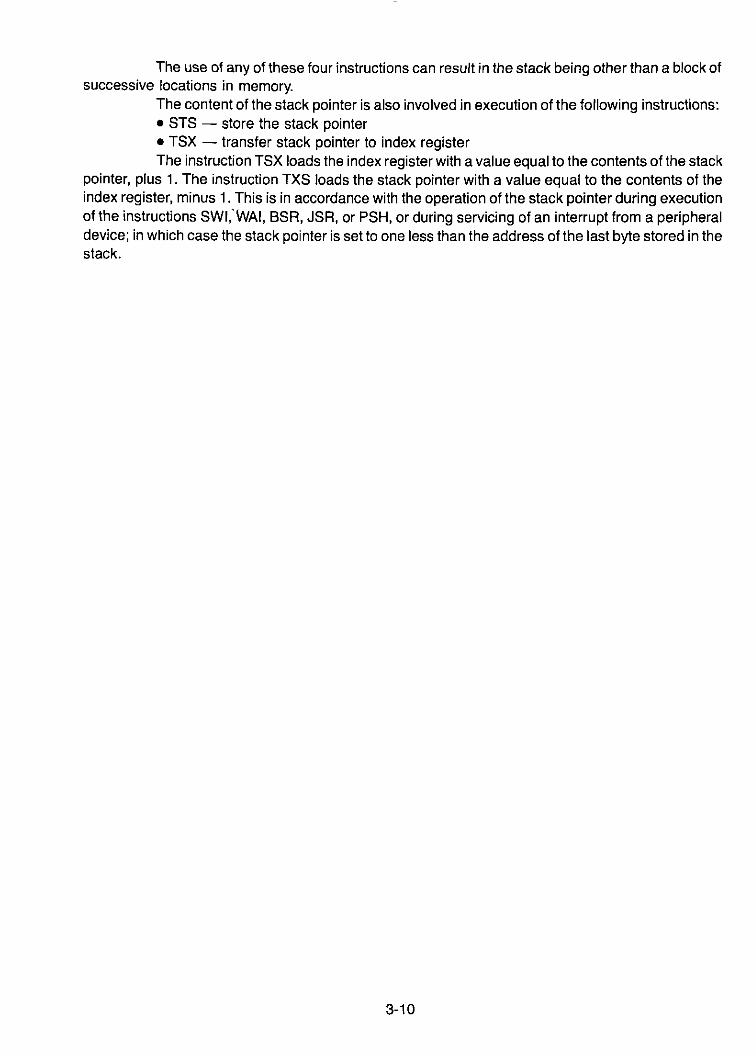
The use of any of these four instructions can result in the stack being other than a block ofsuccessive locations in memory.
The content of the stack pointer is also involved in execution of the following instructions:• STS - store the stack pointer• TSX - transfer stack pointer to index registerThe instruction TSX loads the index register with a value equal to the contents of the stack
pointer, plus 1. The instruction TXS loads the stack pointer with a value equal to the contents of theindex register, minus 1. This is in accordance with the operation of the stack pointer during executionof the instructions SWI,'WAI, BSR, JSR, or PSH, or during servicing of an interrupt from a peripheraldevice; in which case the stack pointer is set to one less than the address of the last byte stored in thestack.
3-10
CHAPTER 4M6800 MICROPROCESSOR ADDRESSING MODES
4.0 ADDRESSING MODES
The assembler scans the operator and operand to determine the proper addressing mode.The addressing modes are:
• Dual Addressing• Accumulator Addressing• Inherent Addressing• Immediate Addressing• Relative Addressing• Indexed Addressing• Direct and Extended Addressing
4.1 DUAL ADDRESSING
Eleven of the executable instructions require addressing of two operands in the operandfield. These instructions are indicated in Figure 4-1 by the column headed Dual Operand. For all ofthese operators the first operand must be either accumulator A or accumulator B. This is specifiedrespectively by A or B as the first character in the operand field, the second character in the operandfield being a SPACE.
For dual addressing the specification of the first operand (either A or B) is separated fromthat of the second operand by one or more SPACE characters.
The second operand is specified in the operand field in accordance with the rules forimmediate, direct, extended, or indexed addressing (as subsequently defined); depending on whichmodes of addressing are valid for the individual operators. (For nmemonic operators which employdual addressing, it is permissible to omit the SPACE between the operator and the first operand field- LDAA LABEL).
4.2 ACCUMULATOR ADDRESSING (SINGLE OPERAND)
Thirteen of the operators address a single operand from the operand field and, thus, canaddress either accumulator A or accumulator B in the microprocessing unit. These operators areindicated by the column headed ACCX in Figure 4-1. This mode of addressing is specified by writingan operand field consisting only of the single character A or B (corresponding to accumulator A oraccumulator B). For this type of addressing, it is then permissible to omit the SPACE between theoperator and the operand field.
For this type of addressing, the assembly of a source instruction results in one byte ofinstruction in the machine language. For operators PUL and PSH, the accumulator mode is the onlyvalid mode of addressing. The remaining eleven operators capable of this mode of addressing canalternatively be used with extended or indexed addressing.
4.3 INHERENT ADDRESSING
In many cases, the mnemonic operator itself specifies one or more registers which containoperands or in which results are saved. For example, the operator ABA requires two operands which
4-1

are located in accumulator A and accumulator B of the microprocessor. The operator also determinesthat the result of execution will be saved in accumulator A.
For some executable instructions, all of the information which may be required for theaddressing is contained in the mnemonic operator, and no operand field is used in the sourcestatement. There are 25 sU~h instructions. These are indicated by the column headed Inherent inFigure 4-1.
Assembly of this type ofsource instruction results in only one byte of machine languagecode. Some other operators which contain addressing information inherently in the mnemonic codealso require further addressing or operand information which is then placed in an operand field.Examples are the operators CPX, LDS, LDX, STS and STX.
4.4 IMMEDIATE ADDRESSING
The operators with which the immediate mode of addressing is permissible are indicatedby the column headed Immediate in Figure 4-1. This mode of addressing is selected by beginning thespecification of the corresponding operand (in the operand field of a source statement) with the poundcharacter "#".
ABAADCADDANDASLASABCCBCSBEABGEBGTBHIBITBLEBLSBLTBMIBNEBPLBAABSABVCBVSCBACLCCLICLACLVCMPCOMCPXOMDECDESOEXEOA
xxx
x
x
x
x(J(J«••••22
••••••••••••••••••••2
••2
••2
•••
!.!!~GI
EE
•222
••••••••2
•••••••••••••••2
•3••••2
•333
••••••••3
•••••••••••••••3
•4
••••3
~GI~c!xw
•44466
••••e
•4
•••••••••••••6
•465•6
••4
•55577
••••••5
•••••••••••••7
•576
•7
••5
...cfCDJ:C
2
••••••••••••••••••••••222
•2
•••2
•44
•
CD>.~
caCDa:
••••••444444
•4444444844
•••••••••••••
INCINSINXJMPJSALOALOSLOXLSANEGNOPORAPSHPULAOLAOAATIATSSBASBCSECSEISEVSTASTSSTXSUBSWITABTAPTBATPATSTTSXTXSWAI
x
x
x
x
x
~ca
X ~(J E(J E« -2 •• •• •• •• •• 2• 3• 32 •2 •• •• 24 •4 •2 •2 •
• •• •• •• 2• •• •• •• •• •• •• 2• •• •• •• •• •2 •• •• •• •
...u.~C
•••••344
•••3
•••••••3
•••4553
•••••••••
1~c~xw6
••3945566
•4
••66•••4
•••5664
•••••6
•••
7
••4856677
•5
••77
•••5
•••6775
•••••7
•••
•44
•••••••2
•••••1052
•222
••••122222
•449
NOTE: Interrupt time is 12 cycles from the end ofthe instruction being executed, except followinga WAI instruction. Then it is 4 cycles.
FIGURE 4-1. Instruction Addressing Modes and Execution Times (Times in Machine Cycles)
4-2

With the immediate mode of addressing, the operand field of the source statement eithercontains the actual value of the operand, or it includes a symbol or an expression which has analgebraic value equal to the value of the operand. The operand may be specified in accordance withany of the following formats:
# Number# Symbol# Expression#'CIn the first three of these alternate forms, the assembler will find or compute a numerical
value ofthe operand. For any executive instruction in the immediate mode of addressing (except CPX,LOS, or LOX), the numeric values must be an integer from 0 to 255 (decimal). For the operators CPX,LOS, or LOX, any value from 0 to 65535 (decimal) is valid.
In the last of the alternate forms (#'C), the apostrophe instructs the assembler to translatethe next character into the corresponding 7-bit ASCII code. The ASCII code so obtained is then thevalue of the operand. The single character "C" can be any character of the ASCII character set with ahexadecimal value from 20 (SP) thru 5F ( ).
For the immediate mode of addressing, the assembler inserts the actual value of theoperand into the machine code. Except for the three operators (CPX, LOS, and LOX), an instruction inthe immediate mode is assembled into two bytes of machine code and the value of the operand isentered in the second byte. When it is a number, the operand is entered in the memory in unsigneda-bit binary code. When it is an ASCII character, the corresponding 7-bit ASCII code applies, using bits0-6 with bit 7 set to zero.
For the three operators (CPX, LOS, or LOX) used in the immediate mode, the sourcestatement is assembled into three bytes of machine code. The numerical operand (which can haveany value from 0 thru FFFF) will be entered in the second and third bytes. The second byte will containthe most significant part of the operand and the third byte will contain the least significant part of theoperand. Both parts are entered into the respective bytes of the memory in unsigned a-bit binary code.
The operators (CPX, LOS, or LOX) in the immediate mode are not normally used with anoperand in the format #'C. However, in such a case, the assembler would place the ASCII codedcharacter "C" in the third byte of the machine code corresponding to the source instruction.
When the immediate mode of addressing is used, the numerical address is in effect that ofthe second byte of machine code which results from assembly of the source instruction. Data flow forthe immediate addressing mode is shown in Figure 4-2.
ACCA
25
MPU
PROGRAMMEMORY
PC I------Ie
GENERAL FLOW
MPU
PROGRAMMEMORY
PC =5002I----K'"
EXAMPLE
FIGURE 4·2. Immediate Addressing Mode Data Flow
4-3

4.5 RELATIVE ADDRESSING
For the relative addressing mode to be valid, there is a rule which limits the distance in themachine language program from the branch instruction to the destination of the branch. The rulewhich applies to the relative addressing mode is that the address of the destination of the branch mustbe within the range specified by:
(PC + 2) - 128 ~ D ~ (PC + 2) + 127where
PC = address of the first byte of the branch instruction.D = address of the destination of the branch instruction.When it is desired to transfer control beyond the range of the branch instructions, this can
be done by using JMP (unconditional jump) or JSA uump to subroutine). These instructions do not usethe relative mode of addressing.
The assembler translates a branch instruction into two bytes of the machine code. Thesecond byte contains a relative address. This is stored as a number in 8-bit, two's complement, binaryform, with a decimal value in the range of -128 to +127. These numbers correspond to the limits oftherange of a branch instruction, as described above.
The relationship between the relative address and the absolute address of the destinationof a branch instruction is expressed by:
D = (PC + 2) + Awhere:
PC = address of the first byte of the branch instructionD = address of the destination of the branch instructionA = the 8-bit, two's complement, binary number, stored in the second byte of the branch
instruction.The relative addressing mode is available only to the conditional branch instructions, the
unconditional branch instruction (BAA), and the branch to subroutine (BSA). None of these sourceinstructions can use any other of the several modes of addressing. The three-character mnemonicinstruction, therefore, is sufficient to determine when the relative mode of addressing will be used forthe assembler. An example of the data flow for the relative addressing mode is shown in Figure 4-3.
4.6 INDEXED ADDRESSING
The Indexed column of Figure 4-1 indicates the instructions for which indexed addressingis valid.
With this mode of addressing, the numerical address is variable; depending on thecontents of the index register. The current address is obtained whenever it is required during theexecution of a program, rather than being predetermined by the assembler as it is for the otheraddressing modes. The operand field of the source statement contains a numerical value which, whenadded to the contents of the index register during execution of the program, will provide the numericaladdress. Alternatively, the operand field may contain a symbol or an expression which the assembleris able to replace by the value which is to be added to the contents of the index register. An example ofthe indexed addressing mode is shown in Figure 4-4.
In indexed addressing, the data for obtaining the numerical address may be written in anyof the formats:
X,XNumber,XSymbol,XExpression,X
4-4

MPU
GENERAL FLOW
MPU
PROGRAMMEMORY
PC = 5008t----4
PC=5025~
EXAMPLE
FIGURE 4-3. Relative Addressing Mode Data Flow
MPU
ADDR = INDX t-----tL~
+ OFFSET ................;"";,,;,,.,..............
PROGRAMMEMORY
PC ......--.....c
OFFSET ~ 255
GENERAL FLOW
MPU
AccannTm5EXrnu
ADDR = 405...............--4
PROGRAMMEMORY
PC = 5006......---<'"
EXAMPLE
FIGURE 4-4. Indexed Addressing Modo
The single character X informs the assembler that the indexed mode is to be used (the character Xbeing reserved to denote the index register).
The format X, when used alone, instructs the assembler that the address of the operand isidentical with the contents of the index register. This format has the same effect on the assembly as ifO,X had been written.
If a symbol or an expression is used rather than a number, the assembler will find orcompute a numerical value of that symbol or expression. The source program must then include otherstatements which define a numerical value for the symbol or which enable the assembler to compute anumerical value for the symbol or expression. Only values from zero to FF (hexadecimal) are valid.
4-5

This value is added to the contents of the index register during execution to obtain the numericaladdress as shown in the following formula:
o = numerical value + Xwhere
X = contents of index registero = numerical addressFor indexed addressing, the source instruction is translated into two bytes of the machine
code. The second byte contains the number, in unsigned a-bit binary form, which is added to thecontents of the index register during execution of the instruction. The number thus obtained is thenumerical address (in accordance with the previous formula).
4.7 DIRECT AND EXTENDED ADDRESSING
In direct addressing, the source instruction is translated into two bytes of machine code.The second byte will contain the address in unsigned a-bit binary form.
In extended addressing, the source instruction is translated into three bytes of machinelanguage. The second of these bytes will contain the highest a bits of the address. The third byte willcontain the lowest a bits of the address. The contents of the second and third bytes will both be codedin unsigned a-bit binary form.
For both direct and extended addressing, the address, which is placed by the assemblerinto the second or third bytes of the machine code, is the absolute numerical address.
As may be seen in Figure 4-1, there are several instructions for which the extended modeof addressing is valid and not the direct mode. For these instructions, when using any of the number,symbol, or expression formats, the assembler will select the extended mode of addressing, regardlessof the value of the numerical address. The source statement will be translated into three bytes of themachine code.
For those instructions which may use the direct mode of addressing as well as theextended mode, the assembler selects the mode according to the following rule: The assembler willselect direct addressing if the numerical address is in the range from 0 to 255 (decimal) and will selectextended addressing if the numerical address exceeds 255 (decimal). Examples of the direct andextended addressing modes are shown in Figures 4-5 and 4-6.
MPU
ADDR""'---0001
PROGRAMMEMORY
PCI----'IC.
ADDR = 05.255
GENERAL FLOW
MPU
ADDR = 100 t--""';";'--f
PROGRAMMEMORY
PC =5004I----r'"
EXAMPLE
FIGURE 4-5. Direct Addressing Mode Data Flow
4-6

MPU
PROGRAMMEMORY
MPU
ADDR = 300 ......4
.......
PROGRAMMEMORY
PC ......---...
ADDR :;, 256
GENERAL FLOW
PC = 5006
EXAMPLE
FIGURE 4-6. Extended Addressing Mode Data Flow
4-7

4-8

APPENDIX ADefinition of the Executable Instructions
A.1 Nomenclature
The following nomenclature is used in the subsequent definitions.
(a) Operators( ) = contents of~ = is transferred to
t lIis pulled from stack"
! = lIis pushed into stack"= Boolean AND
0 = Boolean (Inclusive) OR(±) = Exclusive OR= = Boolean NOT
(b) Registers in the MPUACCA = Accumulator AACCB = Accumulator BACCX = Accumulator ACCA or ACCB
CC Condition codes register
IX = Index register, 16 bitsIXH Index register, higher order 8 bitsIXl = Index register, lower order 8 bits
PC = Program counter, 16 bitsPCH = Program counter, higher order 8 bitsPCl = Program counter, lower order 8 bits
SP = Stack pointerSPH = Stack pointer highSPl Stack pointer low
(c) Memory and AddressingM A memory location (one byte)M +1 = The byte of memory at 0001 plus the address of the memory location indi-
cated by 11M."Rei Relative address (Le. the two's complement number stored in the second byte
of machine code corresponding to a branch instruction).(d) Bits 0 thru 5 of the Condition Codes Register
C = Carry - borrow bit-OV = Two's complement overflow indicator bit-1Z = Zero indicator bit-2N = Negative indicator bit-3I = Interrupt mask bit-4H = Half carry bit-5
(e) Status of Individual Bits BEFORE Execution of an InstructionAn = Bit n of ACCA (n=7,6,5, ... ,0)Bn = Bit n of ACCB (n=7,6,5, ... ,0)IXHn = Bit n of IXH (n=7,6,5, ... ,0)
A-1
II
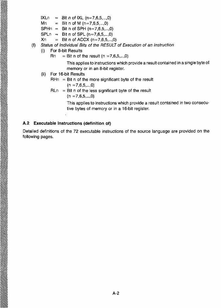
IXLn = Bit n of IXL (n=7,6,5,m,O)Mn = Bit n of M (n=7,6,5, ... ,O)SPHn = Bit n of SPH (n=7,6,5,... ,0)SPLn = Bit n of SPL (n=7,6,5, ... ,O)Xn = Bit n of ACCX (n=7,6,5,m,O)
(f) Status of Individual Bits of the RESULT of Execution of an Instruction(i) For a-bit Results
Rn = Bit n of the result (n =7,6,5, ... ,0)
This applies to instructions which provide a result contained in a single byte ofmemory or in an a-bit register.
(ii) For 16-bit ResultsRHn = Bit n of the more significant byte of the result
(n =7,6,5, ... ,0)RLn = Bit n of the less significant byte of the result
(n =7,6,5, ... ,0)
This applies to instructions which provide a result contained in two consecutive bytes of memory or in a 16-bit register.
A.2 Executable Instructions (definition of)
Detailed definitions of the 72 executable instructions of the source language are provided on thefollowing pages.
A-2

Add Accumulator B to Accumulator A ABA
Condition Codes:
Operation:
Description:
ACCA ~ (ACCA) + (ACCB)
Adds the contents of ACCB to the contents of ACCA and places the result inACCA_
H: Set if there was a carry from bit 3; cleared otherwise_I: Not affected.N: Set if most significant bit of the result is set; cleared otherwise.Z: Set if all bits of the result are cleared; cleared otherwise.V: Set if there was two's complement overflow as a result of the operation;
cleared otherwise.C: Set if there was a carry from the most significant bit of the result; cleared
otherwise.
Boolean Formulae for Condition Codes:H = AJ·B3+B3- Fb+R3'A3N = R7Z = R7' Rs .Rs .R4 .R3 .R2 .R1 .RoV = A7'B7'R7+A7-SrR7C = A7'B7+BrR7+R7'A7
Addressing Modes, Execution Time, and Machine Code (hexadecimal/ octall decimal):
Coding of First (or only)Number of byte of machine code
Addressing Execution Time bytes ofModes (No. of cycles) machine code HEX. OCT. DEC.
Inherent 2 1 1B 033 027
A-3
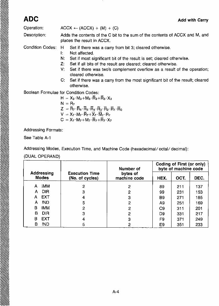
ADC Add with Carry
Operation:
Description:
ACCX ~ (ACCX) + (M) + (C)
Adds the contents of the C bit to the sum of the contents of ACCX and M, andplaces the result in ACCX.
Condition Codes: H Set if there was a carry from bit 3; cleared otherwise.I: Not affected.N: Set if most significant bit of the result is set; cleared otherwise.Z: Set if all bits of the result are cleared; cleared otherwise.V: Set if there was two's complement overflow as a result of the operation;
cleared otherwise.C: Set if there was a carry from the most significant bit of the result; cleared
otherwise.
800lean Formulae for Condition Codes:H = X3·M3+M3·j:b+R3·X3N = R7Z = R7·Rs·Rs·R4·R3·i=b·R1·RoV = X7·M7·R7+X7·M7·R7C = X7'M7+M7'Fh+R7,X7
Addressing Formats:
See Table A-1
Addressing Modes, Execution Time, and Machine Code (hexadecimal/ octal/ decimal):
(DUAL OPERAND)
Coding of First (or only)Number of byte of machine code
Addressing Execution Time bytes ofModes (No. of cycles) machine code HEX. OCT. DEC.
A IMM 2 2 89 211 137A DIR 3 2 99 231 153A EXT 4 3 89 271 185A IND 5 2 A9 251 169B IMM 2 2 C9 311 201B DIR 3 2 D9 331 217B EXT 4 3 F9 371 2498 IND 5 2 E9 351 233
A-4

Coding of First (or only)Number of byte ~f machine code
Addressing Execution Time bytes ofModes (No. of cycles) machine code HEX. OCT. DEC.
A IMM 2 2 8B 213 139A DIR 3 2 9B 233 155A EXT 4 3 BB 273 187A IND 5 2 AB 253 171B IMM 2 2 CB 313 203B DIR 3 2 DB 333 219B EXT 4 3 FB 373 251B IND 5 2 EB 353 235
Add Without Carry ADDOperation: ACCX ~ (ACCX) + (M)
Description: Adds the contents of ACCX and the contents of M and places the result in ACCX_
Condition Codes: H: Set if there was a carry from bit 3; cleared otherwise_I: Not affected.N: Set if most significant bit of the result is set; cleared otherwise.Z: Set if all bits of the result are cleared; cleared otherwise_V: Set if there was two's complement overflow as a result of the operation;
cleared otherwise_C: Set if there was a carry from the most significant bit of the result; cleared
otherwise.
Boolean Formulae for Condition Codes:H = X3-M3+M3-i=b+R3-X3N = R7Z = R7 -R6 -Rs -R4 -R3 .R2 -R1 -RoV = X7-M7-R7+X7-M7-R7C = X7-M7+M7-R7+i=h-X7
Addressing Formats:
See Table A-1
Addressing Modes, Execution Time, and Machine Code (hexadecimal/ octal/ decimal):
(DUAL OPERAND)
IIII
A-5 III
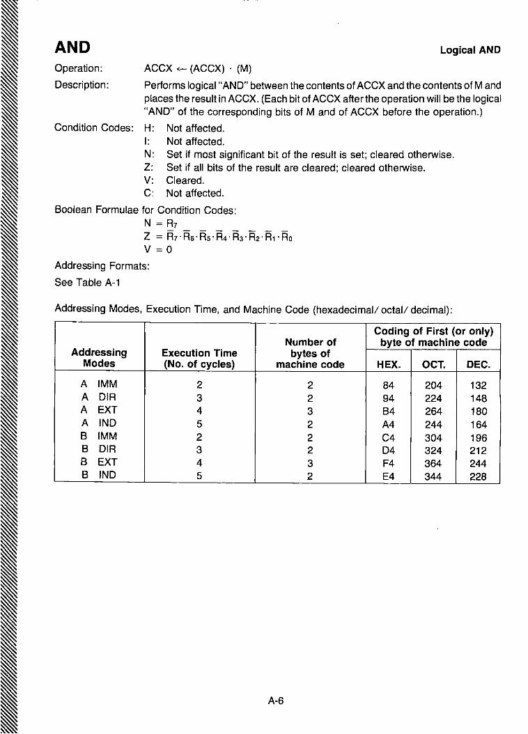
AND Logical AND
Operation:
Description:
ACCX ~ (ACCX) . (M)
Performs logical "AND" between the contents of ACCX and the contents of M andplaces the result in ACCX. (Each bit of ACCX after the operation will be the logical"AND" of the corresponding bits of M and of ACCX before the operation.)
Condition Codes: H: Not affected.I: Not affected.N: Set if most significant bit of the result is set; cleared otherwise.z: Set if all bits of the result are cleared; cleared otherwise.V: Cleared.C: Not affected.
800lean Formulae for Condition Codes:N = R7Z = Fh· R6' RS'R4' Fh'R2' R1·RoV = 0
Addressing Formats:
See Table A-1
Addressing Modes, Execution Time, and Machine Code (hexadecimal/ octal/ decimal):
Coding of First (or only)Number of byte of machine code
Addressing Execution Time bytes ofModes (No. of cycles) machine code HEX. OCT. DEC.
A IMM 2 2 84 204 132A DIR 3 2 94 224 148A EXT 4 3 84 264 180A IND 5 2 A4 244 1648 IMM 2 2 C4 304 1968 DIR 3 2 04 324 2128 EXT 4 3 F4 364 2448 IND 5 2 E4 344 228
A-6

A-7
Addressing Modes, Execution Time, and Machine Code (hexadecimal/ octal/ decimal):
ASL
obo
Coding of First (or only)Number of byte of machine code
Addressing Execution Time bytes ofModes (No. of cycles) machine code HEX. OCT. DEC.
A 2 1 48 110 072B 2 1 58 130 088
EXT 6 3 78 170 120IND 7 2 68 150 104
Description: Shifts all bits of the ACCX or M one place to the left. Bit 0 is loaded with a zero. TheC bit is loaded from the most significant bit of ACCX or M.
Condition Codes: H: Not affected.I: Not affected.N: Set if most significant bit of the result is set; cleared otherwise.Z: Set if all bits of the result are cleared; cleared otherwise.V: Set if, after the completion of the shift operation, EITHER (N is set and C is
cleared) OR (N is cleared and C is set); cleared otherwise.C: Set if, before the operation, the most significant bit of the ACCX or Mwas set;
cleared otherwise.
Boolean Formulae for Condition Codes:N = R7Z = Fh· R6 .Rs .R4· R3 .R2 .R1 .RoV = N Et) C = [N·C] 0 [N·C]
(the foregoing formula assumes values of Nand C after the shift operation)C = M7
Addressing Formats
See Table A-3
Arithmetic Shift Left
Operation:

A-8
Addressing Modes, Execution Time, and Machine Code (hexadecimal/ octal/ decimal):
Coding of First (or only)Number of byte of machine code
Addressing Execution Time bytes ofModes (No. of cycles) machine code HEX. OCT. DEC.
A 2 1 47 107 071B 2 1 57 127 087
EXT 6 3 77 167 119INO 7 2 67 147 103
Arithmetic Shift RightASR
.~---t~~ITJb7 bo
Shifts all bits of ACCX or M one place to the right. Bit 7 is held constant. Bit 0 isloaded into the C bit.
Condition Codes: H: Not affected,I: Not affected.N: Set if the most significant bit of the result is set; cleared otherwise.Z: Set if all bits of the result are cleared; cleared otherwise,V: Set if, after the completion of the shift operation, EITHER (N is set and C is
cleared) OR (N is cleared and C is set); cleared otherwise.C: Set if, before the operation, the least significant bit ofthe ACCX or M was set;
cleared otherwise.
Boolean Formulae for Condition Codes:N = R7Z = i=h'R6' Rs' R4' Ra' R2,R1'RoV = N (f) C = [N·C] 0 [N'C]
(the foregoing formula assumes values of Nand C after the shift operation)C = Mo
Addressing Formats:
See Table A-3
Operation:
Description:

Branch if Carry Clear BeeOperation: PC ~ (PC) + 0002 + Rei if (C)=O
Description: Tests the state of the C bit and causes a branch if C is clear.
See BRA instruction for further details of the execution of the branch.
Condition Codes: Not affected.
Addressing Formats:
See Table A-B.
Addressing Modes, Execution Time, and Machine Code (hexadecimal/ octal/ decimal):
Coding of First (or only)Number of byte of machine code
Addressing Execution Time bytes ofModes (No. of cycles) machine code HEX. OCT. DEC.
REL 4 2 24 044 036
A-9

Addressing Modes, Execution Time, and Machine Code (hexadecimal/ octal/ decimal):
Coding of First (or only)Number of byte of machine code
Addressing Execution Time bytes ofModes (No. of cycles) machine code HEX. OCT. DEC.
REL 4 2 25 045 037
Operation: PC ~ (PC) + 0002 + Rei if (C)=1
Description: Tests the state of the C bit and causes a branch if C is set.
See BRA instruction for further details of the execution of the branch.
Condition Codes: Not affected.
Addressing Formats:
See Table A-a.
Branch if Carry SetBCS
A-10

Branch if Equal BEQOperation: PC of- (PC) + 0002 + Rei if (2)=1
Description: Tests the state of the 2 bit and causes a branch if the 2 bit is set.
See BRA instruction for further details of the execution of the branch.
Condition Codes: Not affected.
Addressing Formats:
See Table A-B.
Addressing Modes, Execution Time, and Machine Code (hexadecimal/ octal/ decimal):
Coding of First (or only)Number of byte of machine code
Addressing Execution Time bytes ofModes (No. of cycles) machine code HEX. OCT. DEC.
REL 4 2 27 047 039
A-11 I

BGE Branch if Greater than or Equal to Zero
Operation: PC ~ (PC) + 0002 + Rei if (N) (f) (V) = 0
i.e. if (ACCX) ~ (M)(Two's complement numbers)
Description: Causes a branch if (N is set and V is set) OR (N is clear and V is clear).
If the BGE instruction is .executed immediately after execution of any of theinstructions CBA, CMP, SBA, or SUB, the branch will occur if and only if the two'scomplement number represented by the minuend (Le. ACCX) was greater than orequal to the two's complement number represented by the subtrahend (Le. M).
See BRA instruction for details of the branch.
Condition Codes: Not affected.
Addressing Formats:
See Table A-B.
Addressing Modes, Execution Time, and Machine Code (hexadecimal/ octal/ decimal):
Coding of First (or only)Number of byte of machine code
Addressing Execution Time bytes ofModes (No. of cycles) machine code HEX. OCT. DEC.
REL 4 2 2C 054 044
A-12

BGTBranch if Greater than Zero
Operation: PC ~ (PC) + 0002 + Rei if (Z) 0 [(N) (f) (V)] = 0
Le. if (ACCX) > (M)(two's complement numbers)
Description: Causes a branch if [Z is clear] AND [(N is set and V is set) OR (N is clear and V isclear)].
If the BGT instruction is executed immediately after execution of any of theinstructions CBA, CMP, SBA, or SUB, the branch will occur if and only if the two'scomplement number represented by the minuend (Le. ACCX) was greater thanthe two's complement number represented by the subtrahend (Le. M).
See BRA instruction for details of the branch.
Condition Codes: Not affected.
Addressing Formats:
See Table A-B.
Addressing Modes, Execution Time, and Machine Code (hexadecimal/ octal/ decimal):
Coding of First (or only)Number of byte of machine code
Addressing Execution Time bytes ofModes (No. of cycles) machine code HEX. OCT. DEC.
REL 4 2 2E 056 046
A-13
I
IIII
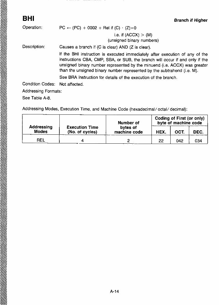
BHI Branch if Higher
Operation: PC ~ (PC) + 0002 + Rei if (C) . (Z)=O
Le. if (ACCX) > (M)(unsigned binary numbers)
Description: Causes a branch if (C is clear) AND (Z is clear).
If the BHI instruction is executed immediately after execution of any of theinstructions CBA, CMP, SBA, or SUB, the branch will occur if and only if theunsigned binary number represented by the minuend (Le. ACCX) was greaterthan the unsigned binary number represented by the subtrahend (Le. M).
See BRA instruction for details of the execution of the branch.
Condition Codes: Not affected.
Addressing Formats:
See Table A-B.
Addressing Modes, Execution Time, and Machine Code (hexadecimal/ octal/ decimal):
Coding of First (or only)Number of byte of machine code
Addressing Execution Time bytes ofModes (No. of cycles) machine code HEX. OCT. DEC.
REL 4 2 22 042 034
A-14
A-15
Addressing Modes, Execution Time, and Machine Code (hexadecimal/ octal/ decimal):
Addressing Formats:
See Table A-1.
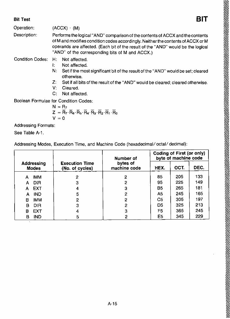
BIT(ACCX) . (M)
Performs the logical"AN0" comparison of the contents of ACCX and the contentsof M and modifies condition codes accordingly. Neither the contents of ACCX or Moperands are affected. (Each bit of the result of the "AND" would be the logical"AND" of the corresponding bits of M and ACCX.)
Condition Codes: H: Not affected.I: Not affected.N: Set if the most significant bit of the result of the "AND" would be set; cleared
otherwise.Z: Set if all bits of the result of the "AND" would be cleared; cleared otherwise.V: Cleared.C: Not affected.
Boolean Formulae for Condition Codes:N = R7Z = Fh· R6 .Rs .R4 .i=b .R2' R1 . RoV = 0
Coding of First (or only)Number of byte of machine code
Addressing Execution Time bytes ofModes (No. of cycles) machine code HEX. OCT. DEC.
A rMM 2 2 85 205 133A DIR 3 2 95 225 149A EXT 4 3 85 265 181A IND 5 2 A5 245 1658 IMM 2 2 C5 305 197B DIR 3 2 05 325 213B EXT 4 3 F5 365 2458 IND 5 2 E5 345 229
Bit Test
Operation:
Description:
A-16
Addressing Modes, Execution Time, and Machine Code (hexadecimal/ octal/ decimal):
Coding of First (or only)Number of byte of machine code
Addressing Execution Time bytes ofModes (No. of cycles) machine code HEX. OCT. DEC.
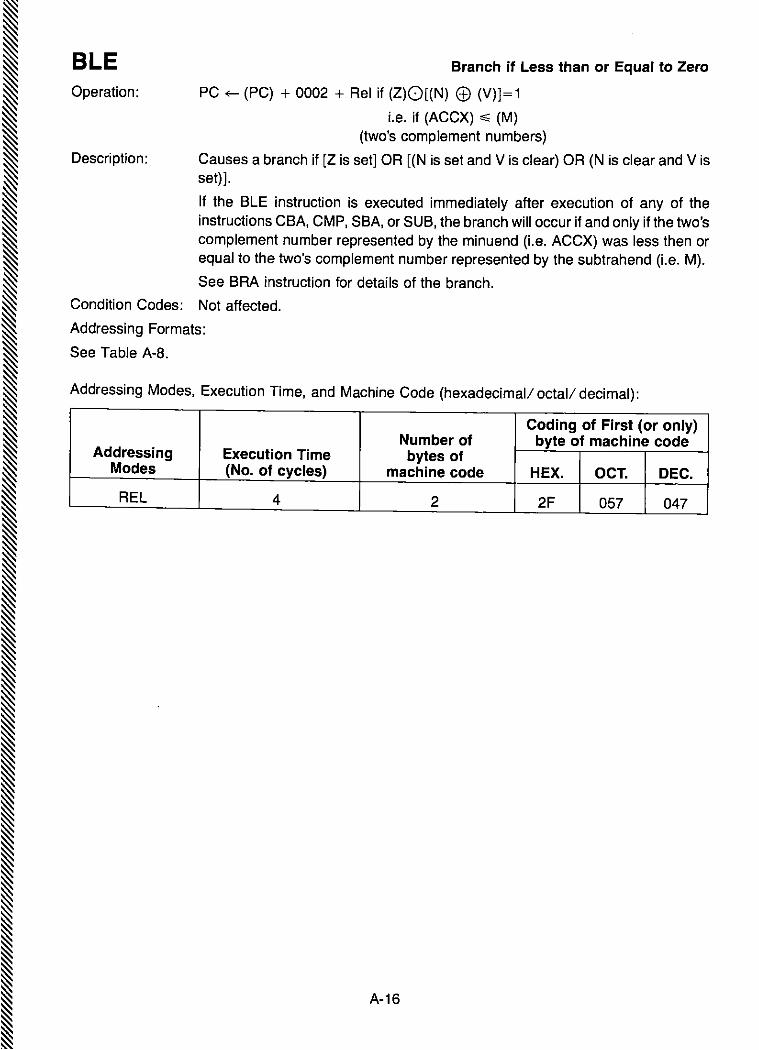
REl 4 2 2F 057 047
Branch if Less than or Equal to ZeroBlEOperation: PC ~ (PC) + 0002 + Rei if (Z)O[(N) ® (V)]=1
i.e. if (ACCX) ~ (M)(two's complement numbers)
Description: Causes a branch if [Z is set] OR [(N is set and V is clear) OR (N is clear and V isset)].
If the BlE instruction is executed immediately after execution of any of theinstructions CSA, CMP, SBA, or SUB, the branch will occur if and only if the two'scomplement number represented by the minuend (Le. ACCX) was less then orequal to the two's complement number represented by the subtrahend (Le. M).
See BRA instruction for details of the branch.
Condition Codes: Not affected.
Addressing Formats:
See Table A-B.

BLSBranch if Lower or Same
Operation: PC ~ (PC) + 0002 + Rei if (C)O(Z) = 1
Le. if (ACCX) ~ (M)(unsigned binary numbers)
Description: Causes a branch if (C is set) OR (Z is set).
If the BLS instruction is executed immediately after execution of any of theinstructions CBA, CMP, SBA, or SUB, the branch will occur if and only if theunsigned binary number represented by the minuend (Le. ACCX) was less thanor equal to the unsigned binary number represented by the subtrahend (Le. M).
See BRA instruction for details of the execution of the branch.
Condition Codes: Not affected.
Addressing Formats:
See Table A-B.
Addressing Modes, Execution Time, and Machine Code (hexadecimal/ octal/ decimal):
Coding of First (or only)Number of byte of machine code
Addressing Execution Time bytes ofModes (No. of cycles) machine code HEX. OCT. DEC.
REL 4 2 23 043 035
A-17

Operation: PC ~ (PC) + 0002 + Rei if (N) <±) (V) = 1
Le. if (ACCX) < (M)(two's complement numbers)
Description: Causes a branch if (N is set and V is clear) OR (N is clear and V is set).
If the BLT instruction is executed immediately after execution of any of theinstructions CBA, CMP, SBA, or SUB, the branch will occur if and only if the two'scomplement number represented by the minuend (Le. ACCX) was less than thetwo's complement number represented by the subtrahend (Le. M).
See BRA instruction for details of the branch.
Condition Codes: Not affected.
Addressing Formats:
See Table A-8.
BLT Branch if Less than Zero
Addressing Modes, Execution Time, and Machine Code (hexadecimal! octal/ decimal):
Coding of First (or only)Number of byte of machine code
Addressing Execution Time bytes ofModes (No. of cycles) machine code HEX. OCT. DEC.
REL 4 2 2D 055 045
A-18
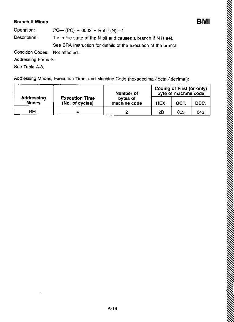
Branch if Minus BMIOperation; PC+- (PC) + 0002 + Rei if (N) = 1
Description; Tests the state of the N bit and causes a branch if N is set.
See BRA instruction for details of the execution of the branch.
Condition Codes: Not affected.
Addressing Formats:
See Table A-a.
Addressing Modes, Execution Time, and Machine Code (hexadecimal/ octal/ decimal):
Coding of First (or only)Number of byte of machine code
Addressing Execution Time bytes ofModes (No. of cycles) machine code HEX. OCT. DEC.
REL 4 2 2B 053 043
A-19

A-20
Addressing Modes, Execution Time, and Machine Code (hexadecimal/ octal/ decimal):
Coding of First (or only)Number of byte of machine code
Addressing Execution Time bytes ofModes (No. of cycles) machine code HEX. OCT. DEC.
REL 4 2 26 046 038
Branch if Not EqualBNEPC ~ (PC) + 0002 + Rei if (2) = 0
Tests the state of the Z bit and causes a branch if the Z bit is clear.
See BRA instruction for details of the execution of the branch.
Condition Codes: Not affected.
Addressing Formats:
See Table A-8.
Operation:
Description:

Branch if Plus BPLOperation: PC ~ (PC) + 0002 + Rei if (N) =0
Description: Tests the state of the N bit and causes a branch if N is clear.
See BRA instruction for details of the execution of the branch.
Condition Codes: Not affected.
Addressing Formats:
See Table A-B.
Addressing Modes, Execution Time, and Machine Code (hexadecimal/ octal/ decimal):
Coding of First (or only)Number of byte of machine code
Addressing Execution Time bytes ofModes (No. of cycles) machine code HEX. OCT. DEC.
REL 4 2 2A 052 042
A-21

A-22
Addressing Modes, Execution Time, and Machine Code (hexadecimal/ octal! decimal):
Coding of First (or only)Number of byte of machine code
Addressing Execution Time bytes ofModes (No. of cycles) machine code HEX. OCT. DEC.
REL 4 2 20 040 032
Branch AlwaysBRAOperation:
Description:
PC ~ (PC) + 0002 + Rei
Unconditional branch to the address given by the foregoing formula, in which R isthe relative address stored as a two's complement number in the second byte ofmachine code corresponding to the branch instruction.
Note: The source program specifies the destination of any branch instruction byits absolute address, either as a numerical value or as a symbol or expressionwhich can be numerically evaluated by the assembler. The assembler obtains therelative address R from the absolute address and the current value ofthe programcounter PC.
Condition Codes: Not affected.
Addressing Formats:
See Table A-B.
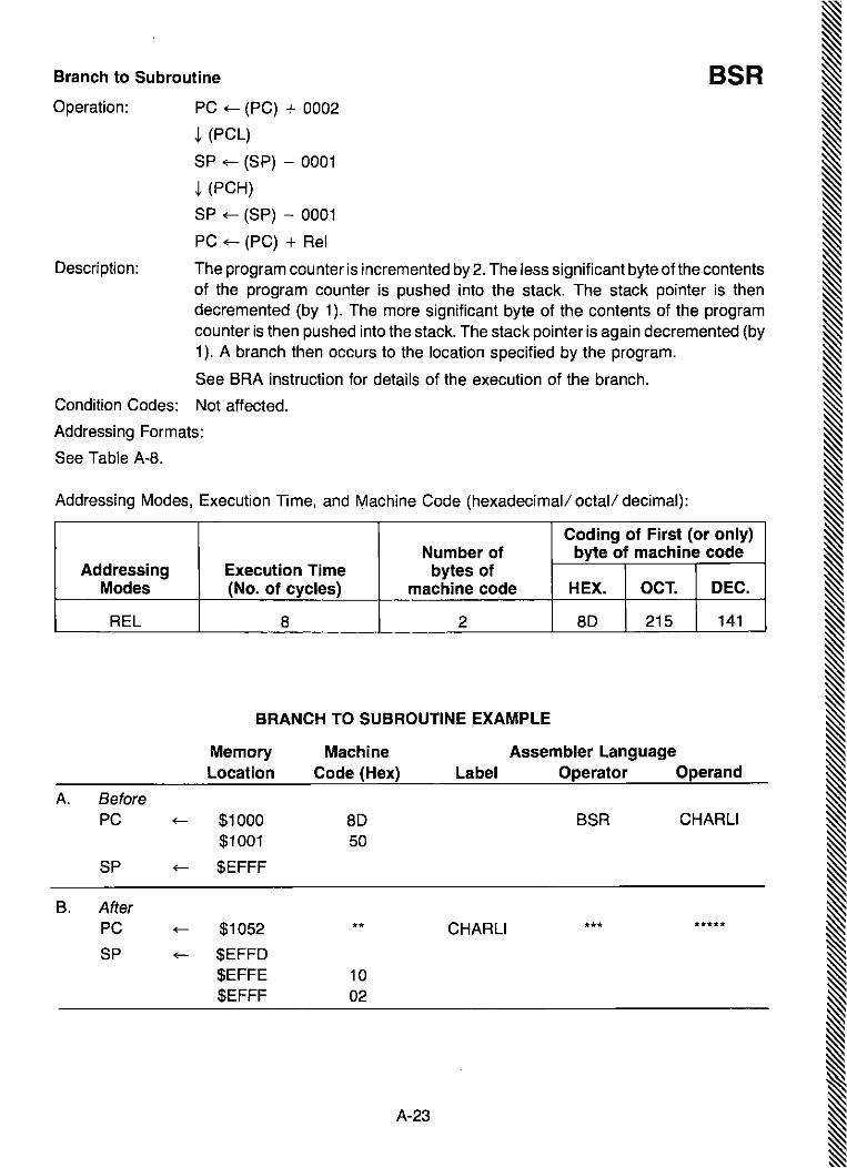
BSRBranch to Subroutine
Operation: PC ~ (PC) + 0002
~ (PCl)
SP ~ (SP) - 0001
~ (PCH)
SP ~ (SP) - 0001
PC ~ (PC) + Rei
Description: The program counter is incremented by 2. The less significant byte ofthe contentsof the program counter is pushed into the stack. The stack pointer is thendecremented (by 1). The more significant byte of the contents of the programcounter is then pushed into the stack. The stack pointer is again decremented (by1). A branch then occurs to the location specified by the program.
See BRA instruction for details of the execution of the branch.
Condition Codes: Not affected.
Addressing Formats:
See Table A-8.
Addressing Modes, Execution Time, and Machine Code (hexadecimal/ octal/ decimal):
Coding of First (or only)Number of byte of machine code
Addressing Execution Time bytes ofModes (No. of cycles) machine code HEX. OCT. DEC.
REl 8 2 80 215 141
BRANCH TO SUBROUTINE EXAMPLE
Memory Machine Assembler LanguageLocation Code (Hex) Label Operator Operand
A. BeforePC ~ $1000 80 BSR CHARLI
$1001 50
SP ~ $EFFF
B. AfterPC ~ $1052 ** CHARLI *** *****
SP ~ $EFFD$EFFE 10$EFFF 02
A-23
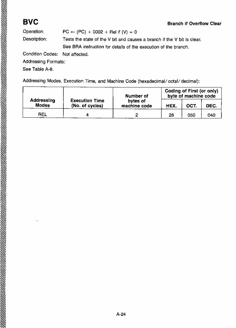
A-24
Addressing Modes, Execution Time, and Machine Code (hexadecimal/ octal/ decimal):
Coding of First (or only)Number of byte of machine code
Addressing Execution Time bytes ofModes (No. of cycles) machine code HEX. OCT. DEC.
REL 4 2 28 050 040
Branch if Overflow ClearBveOperation: PC ~ (PC) + 0002 + Rei if (V) = 0
Description: Tests the state of the V bit and causes a branch if the V bit is clear.
See BRA instruction for details of the execution of the branch.
Condition Codes: Not affected.
Addressing Formats:
See Table A-8.
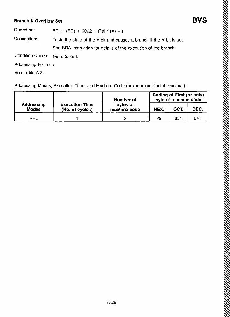
Coding of First (or only)Number of byte of machine code
Addressing Execution Time bytes ofModes (No. of cycles) machine code HEX. OCT. DEC.
REL 4 2 29 051 041
Operation:
Description:
Branch if Overflow Set
PC ~ (PC) + 0002 + Rei if (V) =1
Tests the state of the V bit and causes a branch if the V bit is set.
See BRA instruction for details of the execution of the branch.
Condition Codes: Not affected.
Addressing Formats:
See Table A-B.
Addressing Modes, Execution Time, and Machine Code (hexadecimal/ octal/ decimal):
A-25
BVS

A-26
Coding of First (or only)Number of byte of machine code
Addressing Execution Time bytes ofModes (No. of cycles) machine code HEX. OCT. DEC.
INHERENT 2 1 11 021 017
Compare Accumulators
Operation:
Description:
(ACCA) - (ACCB)
Compares the contents ofACCA and the contents of ACCB and sets the conditioncodes, which may be used for arithmetic and logical conditional branches. Bothoperands are unaffected_
Condition Codes: H: Not affected_I: Not affected.N: Set if the most significant bit of the result of the subtraction would be set;
cleared otherwise.z: Set if all bits of the result of the subtraction would be cleared; cleared
otherwise_V: Set if the subtraction would cause two's complement overflow; cleared
otherwise_C: Set if the subtraction would require a borrow into the most significant bit of
the result; clear otherwise.
Boolean Formulae for Condition Codes:N = R7Z = R7-R6-Rs-R4·R3·R2·R1· RoV = A7"Eh'Fh+A7'B7'R7C = A7' B7+B7·R7+R7·A7
Addressing Modes, Execution Time, and Machine Code (hexadecimal/ octal/ decimal):
CBA

Clear Carry CLCOperation: C bit ~ 0
Description: Clears the carry bit in the processor condition codes register.
Condition Codes: H: Not affected.I: Not affected.N: Not affected.Z: Not affected.V: Not affected.C: Cleared
Boolean Formulae for Condition Codes:C =0
Addressing Modes, Execution Time, and Machine Code (hexadecimal/ octal/ decimal):
Coding of First (or only)Number of byte of machine code
Addressing Execution Time bytes ofModes (No. of cycles) machine code HEX. OCT. DEC.
INHERENT 2 1 OC 014 012
A-27

A-28
Addressing Modes, Execution Time, and Machine Code (hexadecimal/ octal/ decimal):
Coding of First (or only)Number of byte of machine code
Addressing Execution Time bytes ofModes (No. of cycles) machine code HEX. OCT. DEC.
INHERENT 2 1 OE 016 014
Clear Interrupt Mask
I bit ~O
Clears the interrupt mask bit in the processor condition codes register. Thisenables the microprocessor to service an interrupt from a peripheral device ifsignalled by a high state of the "Interrupt Request" control input.
Condition Codes: H: Not affected.I: Cleared.N: Not affected.z: Not affected.V: Not affected.C: Not affected.
Boolean Formulae for Condition Codes:I =0
Operation:
Description:
ell
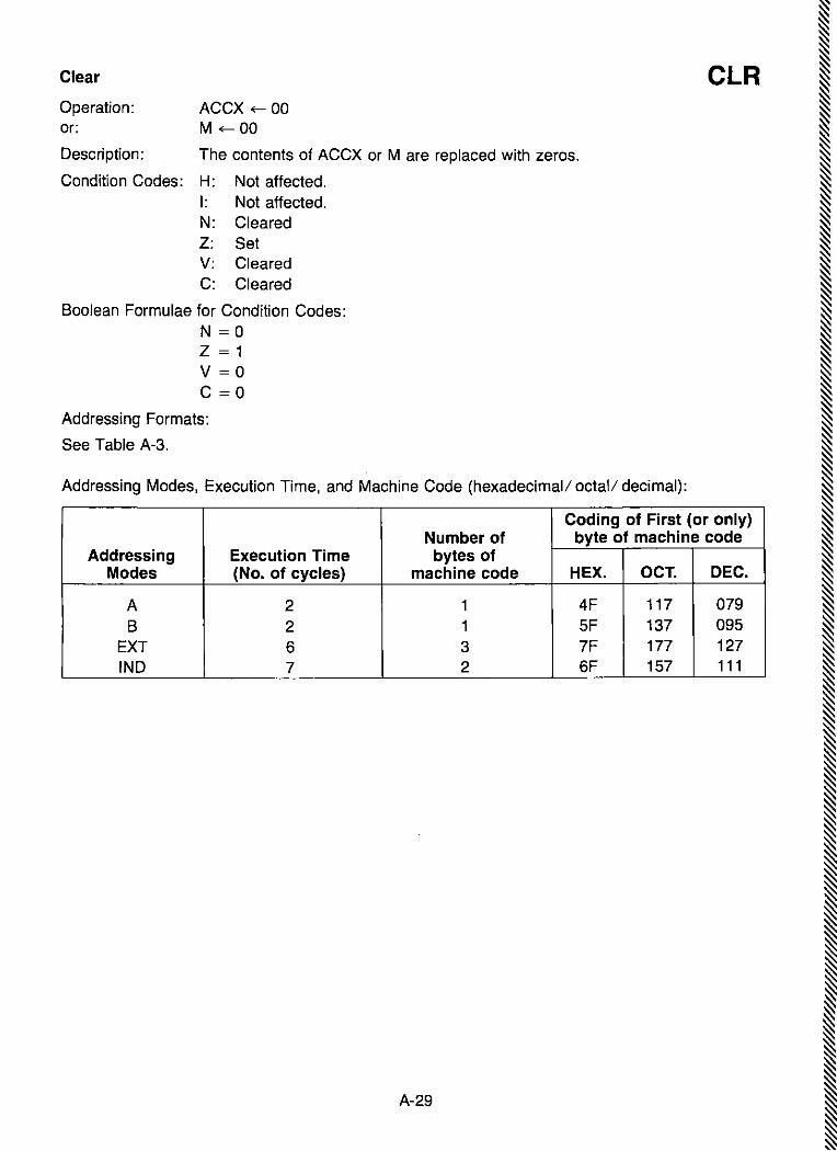
C~r CLROperation: ACCX ~ 00or: M ~ 00
Description: The contents of ACCX or M are replaced with zeros.
Condition Codes: H: Not affected.I: Not affected.N: ClearedZ: SetV: ClearedC: Cleared
Boolean Formulae for Condition Codes:N = 0Z = 1V = 0C =0
Addressing Formats:
See Table A-3.
Addressing Modes, Execution Time, and Machine Code (hexadecimal/ octal! decimal):
Coding of First (or only)Number of byte of machine code
Addressing Execution Time bytes ofModes (No. of cycles) machine code HEX. OCT. DEC.
A 2 1 4F 117 079B 2 1 SF 137 095
EXT 6 3 7F 177 127IND 7 2 6F 157 111
A-29
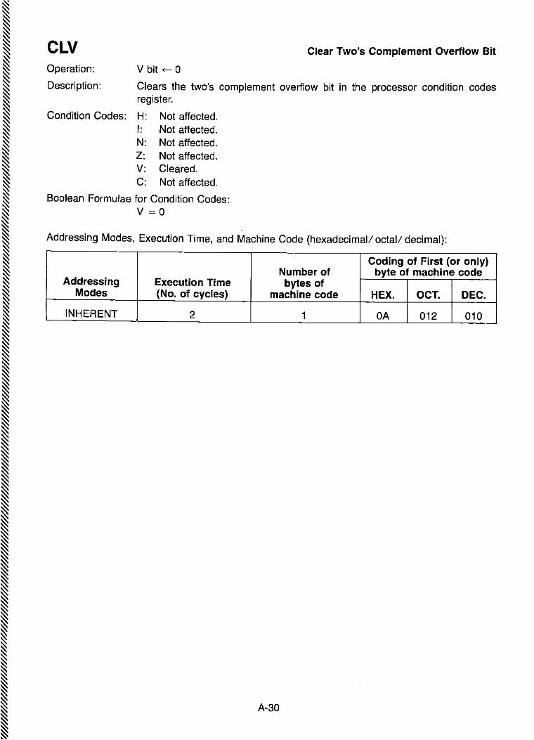
A-30
Addressing Modes, Execution Time, and Machine Code (hexadecimal/ octall decimal):
Coding of First (or only)Number of byte of machine code
Addressing Execution Time bytes ofModes (No. of cycles) machine code HEX. OCT. DEC.
INHERENT 2 1 OA 012 010
Clear Two's Complement Overflow Bit
V bit +- 0
Clears the two's complement overflow bit in the processor condition codesregister.
Condition Codes: H: Not affected.I: Not affected.N: Not affected.Z: Not affected.V: Cleared.C: Not affected.
Boolean Formulae for Condition Codes:V =0
elVOperation:
Description:

A-31
Addressing Modes, Execution Time, and Machine Code (hexadecimal/ octal/ decimal):
(DUAL OPERAND)
Coding of First (or only)Number of byte of machine code
Addressing Execution Time bytes ofModes (No. of cycles) machine code HEX. OCT. DEC.
A IMM 2 2 81 201 129A DIR 3 2 91 221 145A EXT 4 3 B1 261 177A IND 5 2 A1 241 161B IMM 2 2 C1 301 193B OIR 3 2 01 321 209B EXT 4 3 F1 361 241B INO 5 2 E1 341 225
CMP(ACCX) - (M)
Compares the contents of ACCX and the contents of M and determines thecondition codes, which may be used subsequently for controlling conditionalbranching. Both operands are unaffected.
Condition Codes: H: Not affected.I: Not affected.N: Set if the most significant bit of the result of the subtraction would be set;
cleared otherwise.Z: Set if all bits of the result of the subtraction would be cleared; cleared
otherwise.V: Set if the subtraction would cause two's complement overflow; cleared
otherwise.C: Carry is set if the absolute value of the contents of memory is larger than the
absolute value of the accumulator; reset otherwise,
Boolean Formulae for Condition Codes:N = R7Z = Fh'R6'Rs'R4'R3'R2'R1'RoV = X7,M7·R7+X7· M7'R7C = X7·M7+M7·R7+R7,X7
Addressing Formats:
See Table A-1.
Compare
Operation:
Description:

A-32
Addressing Modes, Execution Time, and Machine Code (hexadecimal/ octal/ decimal):
Coding of First (or only)Number of byte of machine code
Addressing Execution Time bytes ofModes (No. of cycles) machine code HEX. OCT. DEC.
A 2 1 43 103 067B 2 1 53 123 083
EXT 6 3 73 163 115INO 7 2 63 143 . 099
ComplementCOMOperation: ACCX ~ == (ACCX) = FF - (ACCX)or: M ~ = (M) = FF - (M)
Description: Replaces the contents of ACCX or M with its one's complement. (Each bit of thecontents of ACCX or M is replaced with the complement of that bit.)
Condition Codes: H: Not affected.I: Not affected_N: Set if most significant bit of the result is set; cleared otherwise.z: Set if all bits of the result are cleared; cleared otherwise.V: Cleared_C: Set.
Boolean Formulae for Condition Codes:N = R7Z = R7-R6·Rs-R4·j:b· R2-R1-RoV = 0C = 1
Addressing Formats:
See Table A-3.

Compare Index Register CPXOperation: (IXL) - (M + 1)
(IXH) - (M)
Description: The more significant byte of the contents of the index register is compared withthe contents of the byte of memory at the address specified by the program. Theless significant byte of the contents of the index register is compared with thecontents of the next byte of memory, at one plus the address specified by theprogram. The Z bit is set or reset according to the results of these comparisons,and may be used subsequently for conditional branching.
The N and V bits, though determined by this operation, are not intended forconditional branching.
The C bit is not affected by this operation.
Condition Codes: H: Not affected.I: Not affected.N: Set if the most significant bit of the result of the subtraction from the more
significant byte of the index register would be set; cleared otherwise.Z: Set if all bits of the results of both subtractions would be cleared; cleared
otherwise.V: Set if the subtraction from the more significant byte of the index register
would cause two's complement overflow; cleared otherwise.C: Not affected.
Boolean Formulae for Condition Codes:N = RH7Z = (RH7' RHs' RHs' RH4' RH3' RH2' RH1' RHa)'
(RL7' RLs' RLs· R1.4· Ru' RL2' RL1 .RLa)V = IXH7·M7·RH7+IXH7·M7·RH7
Addressing Formats:
See Table A-5.
Addressing Modes, Execution Time, and Machine Code (hexadecimal/ octal/ decimal):
Coding of First (or only)Number of byte of machine code
Addressing Execution Time bytes ofModes (No. of cycles) machine code HEX. OCT. DEC.
IMM 3 3 8C 214 140DIR 4 2 9C 234 156EXT 5 3 BC 274 188INO 6 2 AC 254 172
A-33

A-34
Decimal Adjust ACCA
Adds hexadecimal numbers 00, 06, 60, or 66 to ACCA, and may also setthe carry bit, as indicated in the following table:
DAA
Note: Columns (1) through (4) of the above table represent all possible cases which can result fromany of the operations ABA, ADD, or ADC, with initial carry either set or clear, applied to twobinary-coded-decimal operands. The table shows hexadecimal values.
Description: If the contents of ACCA and the state of the carry-borrow bit C and the half-carry bit Hareall the result of applying any of the operations ABA, ADD, or ADC to binary-codeddecimal operands, with or without an initial carry, the DAA operation will function asfollows.
Subject to the above condition, the DAA operation will adjust the contents of ACCA andthe C bit to represent the correct binary-coded-decimal sum and the correct state of thecarry.
Condition Codes: H:I:N:z:V:C:
Not affected.Not affected.Set if most significant bit of the result is set; cleared otherwise.Set if all bits of the result are cleared; cleared otherwise.Not defined.Set or reset according to the same rule as if the DAA and an immediatelypreceding ABA, ADD, or ADC were replaced by a hypothetical binarycoded-decimal addition.
Boolean Formulae for Condition Codes:N = R7Z = i=h'R6'Rs' R4·j:b· R2·R1·RoC = See table above.
Operation:
State of Number State ofC-bit Upper Initial Lower Added C-bit
before Half-byte Half-carry to ACCA afterDAA (bits 4-7) H-bit (bits 0-3) byDAA DAA
(Col. 1) (Col. 2) (Col.3) (Col. 4) (Col. 5) (Col. 6)
0 0-9 0 0-9 00 00 0-8 0 A-F 06 00 0-9 1 0-3 06 0
0 A-F 0 0-9 60 10 9-F 0 A-F 66 10 A-F 1 0-3 66 1
1 0-2 0 0-9 60 11 0-2 0 A-F 66 11 0-3 1 0-3 66 1

Addressing Modes, Execution Time, and Machine Code (hexadecimal/ octal/ decimal):
Coding of First (or only)Number of byte of machine code
Addressing Execution Time bytes ofModes (No. of cycles) machine code HEX. OCT. DEC.
INHERENT 2 1 19 031 025
A-35

Operation: ACCX ~ (ACCX) - 01or: M ~ (M) - 01
Description: Subtract one from the contents of ACCX or M_
The N, Z, and V condition codes are set or reset according to the results of thisoperation.
The C bit is not affected by the operation_
Condition Codes: H: Not affected_I: Not affected_N: Set if most significant bit of the result is set; cleared otherwise.Z: Set if all bits of the result are cleared; cleared otherwise.V: Set if there was two's complement overflow as a result of the operation;
cleared otherwise. Two's complement overflow occurs if and only if (ACCX)or (M) was 80 before the operation_
C: Not affected_
Boolean Formulae for Condition Codes:N = R7Z = R7-R6-Rs-Rs-R4-R3-R2-R1-RoV = X7-X6-XS-X4-X3-X2-XO = R7-R6-Rs- R4-R3-R2-R1-Ro
Addressing Formats:
See Table A-3_
DEC Decrement
Addressing Modes, Execution Time, and Machine Code (hexadecimal/ octal/ decimal):
Coding of First (or only)Number of byte of machine code
Addressing Execution Time bytes ofModes (No. of cycles) machine code HEX. OCT. DEC.
A 2 1 4A 112 074B 2 1 5A 132 090
EXT 6 3 7A 172 122IND 7 2 6A 152 106
A-36
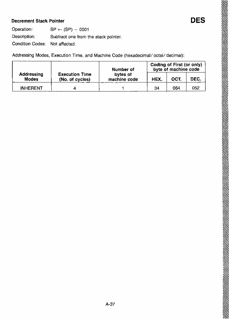
Decrement Stack Pointer DESOperation: SP ~ (SP) - 0001
Description: Subtract one from the stack pointer.
Condition Codes: Not affected.
Addressing Modes, Execution Time, and Machine Code (hexadecimal/ octal/ decimal):
Coding of First (or only)Number of byte of machine code
Addressing Execution Time bytes ofModes (No. of cycles) machine code HEX. OCT. DEC.
INHERENT 4 1 34 064 052
A-37
II~
II
~~~~~~~~~
II

A-38
Addressing Modes, Execution Time, and Machine Code (hexadecimal/ octal/ decimal):
Coding of First (or only)Number of byte of machine code
Addressing Execution Time bytes ofModes (No. of cycles) machine code HEX. OCT. DEC.
INHERENT 4 1 09 011 009
Decrement Index Register
Operation: IX ~ (IX) - 0001
Description: Subtract one from the index register.
Only the Z bit is set or reset according to the result of this operation.
Condition Codes: H: Not affected.I: Not affected.N: Not affected.Z: Set if all bits of the result are cleared; cleared otherwise.V: Not affected.C: Not affected.
Boolean Formulae for Condition Codes:Z = (RH7·RH6·RHs·RH4·RH3· RH2·RH1· RHo)·
(RL7· RL6' RLs' Rl4· Rl3· RL2' RL1 . RLo)
DEX

A-39
Addressing Modes, Execution Time, and Machine Code (hexadecimal/ octal/ decimal):
Addressing Formats:
See Table A-1.
EOR
Coding of First (or only)Number of byte of machine code
Addressing Execution Time bytes ofModes (No. of cycles) machine code HEX. OCT. DEC.
A IMM 2 2 88 210 136A DIR 3 2 98 230 152A EXT 4 3 88 270 184A IND 5 2 A8 250 1688 IMM 2 2 C8 310 2008 DIR 3 2 D8 330 2168 EXT 4 3 Fa 370 2488 IND 5 2 E8 350 232
ACCX ~ (ACCX) @ (M)
Perform logical "EXCLUSIVE OR" between the contents of ACCX and thecontents of M, and place the result in ACCX. (Each bit of ACCX after the operationwill be the logical "EXCLUSIVE OR" of the corresponding bit of M and ACCXbefore the operation.)
Condition Codes: H: Not affected.I: Not affected.N: Set if most significant bit of the result is' set; cleared otherwise.z: Set if all bits of the result are cleared; cleared otherwise.V: ClearedC: Not affected.
800lean Formulae for Condition Codes:N = R7Z = Fh· R6' Rs' R4' R3' R2' R1 .RoV = 0
Operation:
Description:
Exclusive OR

A-40
Addressing Modes, Execution Time, and Machine Code (hexadecimal/ octal/ decimal):
Coding of First (or only)Number of byte of machine code
Addressing Execution Time bytes ofModes (No. of cycles) machine code HEX. OCT. DEC.
A 2 1 4C 114 076B 2 1 5C 134 092
EXT 6 3 7C 174 124IND 7 2 6C 154 108
IncrementINCOperation: ACCX ~ (ACCX) + 01or: M ~ (M) + 01
Description: Add one to the contents of ACCX or M.
The N, Z, and V condition codes are set or reset according to the results of thisoperation.
The C bit is not affected by the operation.
Condition Codes: H: Not affected.I: Not affected.N: Set if most significant bit of the result is set; cleared otherwise.Z: Set if all bits of the result are cleared; cleared otherwise.V: Set if there was two's complement overflow as a result of the operation;
cleared otherwise. Two's complement overflow will occur if and only if(ACCX) or (M) was 7F before the operation.
C: Not affected.
Boolean Formulae for Condition Codes:N = R7Z = R7'R6'Rs'R4'R3'R2'R1'RoV = X7·X6·XS,X4,X3·X2,X1'XOC = R7'R6'Rs'R4'R3'R2'R1'Ro
Addressing Formats:
See Table A-3,

Increment Stack Pointer INSOperation: SP ~ (SP) + 0001
Description: Add one to the stack pointer.
Condition Codes: Not affected.
Addressing Modes, Execution Time, and Machine Code (hexadecimal/ octal/ decimal):
Coding of First (or only)Number of byte of machine code
Addressing Execution Time bytes ofModes (No. of cycles) machine code HEX. OCT. DEC.
INHERENT 4 1 31 061 049
A-41

A-42
Addressing Modes, Execution Time, and Machine Code (hexadecimal/ octal/ decimal):
Coding of First (or only)Number of byte of machine code
Addressing Execution Time bytes ofModes (No. of cycles) machine code HEX. OCT. DEC.
INHERENT 4 1 08 010 008
Increment Index Register
IX ~ (IX) + 0001
Add one to the index register.
Only the Z bit is set or reset according to the result of this operation.
Condition Codes: H: Not affected.I: Not affected.N: Not affected.Z: Set if all 16 bits of the result are cleared; cleared otherwise.V: Not affected.C: Not affected.
Boolean Formulae for Condition Codes:Z = (RH7' RH6' RHs' RH4' RH3' RH2' RHl . RHo)'
(RL7' RL6' RLs· RLt· RG· RL2' RLl . RLo)
Operation:
Description:
INX

A-43
Addressing Modes, Execution Time, and Machine Code (hexadecimal/ octal/ decimal):
Coding of First (or only)Number of byte of machine code
Addressing Execution Time bytes ofModes (No. of cycles) machine code HEX. OCT. DEC.
EXT 3 3 7E 176 126IND 4 2 6E 156 110
JMPOperation: PC ~ numerical address
Description: A jump occurs to the instruction stored at the numerical address. The numericaladdress is obtained according to the rules for EXTended or INDexed addressing.
Condition Codes: Not affected.
Addressing Formats:
See Table A-7.
Jump

A-44
Addressing Modes, Execution Time, and Machine Code (hexadecimal/ octal/ decimal):
Coding of First (or only)Number of byte of machine code
Addressing Execution Time bytes ofModes (No. of cycles) machine code HEX. OCT. DEC.
EXT 9 3 BD 275 189IND 8 2 AD 255 173
Jump to Subroutine
JUMP TO SUBROUTINE EXAMPLE (extended mode)
Memory Machine Assembler LanguageLocation Code (Hex) Label Operator Operand
A. Before:PC ~ $OFFF BD JSR CHARLI
$1000 20$1001 77
SP ~ $EFFF
B. After:PC $2077 ** CHARLI *** *****
~
SP ~ $EFFD$EFFE 10$EFFF 02
JSROperation:Either: PC ~ (PC) + 0003 (for EXTended addressing)or: PC ~ (PC) + 0002 (for INDexed addressing)Then: ~ (PCl)
SP ~ (SP) - 0001~ (PCH)SP ~ (SP) - 0001PC ~ numerical address
Description: The program counter is incremented by 3 or by 2, depending on the addressingmode, and is then pushed onto the stack, eight bits at a time. The stack pointerpoints to the next empty location in the stack. A jump occurs to the instructionstored at the numerical address. The numerical address is obtained according tothe rules for ~XTended or INDexed addressing.
Condition Codes: Not affected.
Addressing Formats:
See Table A-7.

A-45
Addressing Formats:
See Table A-1.
Addressing Modes, Execution Time, and Machine Code (hexadecimal/ octal/ decimal):
(DUAL OPERAND)
LOA
Coding of First (or only)Number of byte of machine code
Addressing Execution Time bytes ofModes (No. of cycles) machine code HEX. OCT. DEC.
A IMM 2 2 86 206 134A DIR 3 2 96 226 150A EXT 4 3 86 266 182A IND 5 2 A6 246 166B IMM 2 2 C6 306 1988 DIR 3 2 06 326 2148 EXT 4 3 F6 366 246B IND 5 2 E6 346 230
ACCX ~ (M)
Loads the contents of memory into the accumulator. The condition codes are setaccording to the data.
Condition Codes: H: Not affected.I: Not affected.N: Set if most significant bit of the result is set; cleared otherwise.Z: Set if all bits of the result are cleared; cleared otherwise.V: Cleared.C: Not affected.
Boolean Formulae for Condition Codes:N = R7Z = Fh· RG· Rs· R4· R3' R2' Rl· RoV = 0
Operation:
Description:
Load Accumulator
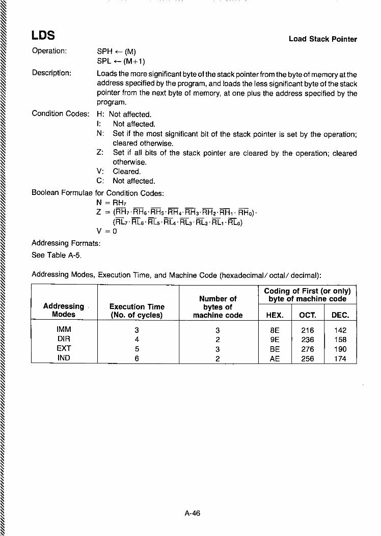
A-46
Addressing Modes, Execution Time, and Machine Code (hexadecimal! octal! decimal):
Coding of First (or only)Number of byte of machine code
Addressing . Execution Time bytes ofModes (No. of cycles) machine code HEX. OCT. DEC.
IMM 3 3 8E 216 142DIA 4 2 9E 236 158EXT 5 3 BE 276 190INO 6 2 AE 256 174
Load Stack Pointer
Operation: SPH ~ (M)SPL ~ (M+1)
Description: Loads the more significant byte of the stack pointer from the byte of memory at theaddress specified by the program, and loads the less significant byte of the stackpointer from the next byte of memory, at one plus the address specified by theprogram.
Condition Codes: H: Not affected.I: Not affected.N: Set if the most significant bit of the stack pointer is set by the operation;
cleared otherwise.Z: Set if all bits of the stack pointer are cleared by the operation; cleared
otherwise.V: Cleared.C: Not affected.
Boolean Formulae for Condition Codes:N = RH7Z = (AH7·AH6·AHs·AH4·AH3·AH2·AH1· AHo)'
(AL7' AL6' ALs· Al4· Au' AL2' ALl' ALa)V =0
Addressing Formats:
See Table A-5.
LOS

Load Index Register LOXOperation: IXH ~ (M)
IXL ~ (M+1)
Description: Loads the more significant byte of the index register from the byte of memory atthe address specified by the program, and loads the less significant byte of theindex register from the next byte of memory, at one plus the address specified bythe program.
Condition Codes: H: Not affected.I: Not affected.N: Set if the most significant bit of the index register is set by the operation;
cleared otherwise.Z: Set if all bits of the index register are cleared by the operation; cleared
otherwise.V: Cleared.C: Not affected.
Boolean Formulae for Condition Codes:N = RH7Z = (RH7' RHs' RHs' RH4' RH3 . RH2' RH1 . RHo)'
(RL7' RLs' RLs· Rl4' Rl3· RL2' RLl .RLo)V = 0
Addressing Formats:
See Table A-5.
Addressing Modes, Execution Time, and Machine Code (hexadecimal/ octal/ decimal):
Coding of First (or only)Number of byte of machine code
Addressing Execution Time bytes ofModes (No. of cycles) machine code HEX. OCT. DEC.
IMM 3 3 CE 316 206DIR 4 2 DE 336 222EXT 5 3 FE 376 254IND 6 2 EE 356 238
A-47

A-48
Addressing Modes, Execution Time, and Machine Code (hexadecimal/ octal/ decimal):
Logical Shift Right
Operation:
Coding of First (or only)Number of byte of machine code
Addressing Execution Time bytes ofModes (No. of cycles) machine code HEX. OCT. DEC.
A 2 1 44 104 068B 2 1 54 124 084
EXT 6 3 74 164 116IND 7 2 64 144 100
o-'~--,----r.._.....L...-...---L-_....L----L------JL...-....I ---I"~ IT]b7 bo
Description: Shifts all bits of ACCX or M one place to the right. Bit 7 is loaded with a zero. The Cbit is loaded from the least significant bit of ACCX or M.
Condition Codes: H: Not affected.I: Not affected.N: Cleared.z: Set if all bits of the result are cleared; cleared otherwise.V: Set if, after the completion of the shift operation, EITHER (N is set and C is
cleared) OR (N is cleared and C is set); cleared otherwise.C: Set if, before the operation, the least significant bit of the ACCX or M was set;
cleared otherwise.
Boolean Formulae for Condition Codes:N = 0Z = R7·R6·Rs·R4·R3·R2·R1·RoV = N (i) C = [N'C] 0 [N·C]
(the foregoing formula assumes values of Nand C after the shift operation).C = Mo
Addressing Formats:
See Table A-3.
LSR

Negate NEG
Description:
Operation:or:
ACCX +- - (ACCX) = 00 - (ACCX)M +- - (M) = 00 - (M)
Replaces the contents of ACCX or M with its two's complement. Note that 80 is leftunchanged,
Condition Codes: H: Not affected_I: Not affected,N: Set if most significant bit of the result is set; cleared otherwise_z: Set if all bits of the result are cleared; cleared otherwise_V: Set if there would be two's complement overflow as a result of the implied
subtraction from zero; this will occur if and only if the contents of ACCX or Mis 80_
C: Set if there would be a borrow in the implied subtraction from zero; the C bitwill be set in all cases except when the contents of ACCX or M is 00_
Boolean Formulae for Condition Codes:N = R7Z = i=h-Rs-Rs-R4' Fb-R2-R1-RoV = R7'Rs-Rs-R4-R3-R2'R1-RoC = R7+Rs+Rs+R4+R3+R2+R1 +Ro
Addressing Formats:
See Table A-3_
Addressing Modes, Execution Time, and Machine Code (hexadecimal! octal! decimal):
Coding of First (or only)Number of byte of machine code
Addressing Execution Time bytes ofModes {No. of cycles} machine code HEX. OCT. DEC.
A 2 1 40 100 064B 2 1 50 120 080
EXT 6 3 70 160 112IND 7 2 60 140 096
A-49

I
NOP No Operation
Description: This is a single-word instruction which causes only the program counter tobe incremented. No other registers are affected.
Condition Codes: Not affected.
Addressing Modes, Execution Time, and Machine Code (hexadecimal/ octal/ decimal):
Coding of First (or only)Number of byte of machine code
Addressing Execution Time bytes ofModes (No. of cycles) machine code HEX. OCT. DEC.
INHERENT 2 1 01 001 001
A-50

Addressing Formats:
See Table A-1.
Addressing Modes, Execution Time, and Machine Code (hexadecimal/ octal/ decimal):
(DUAL OPERAND)
Coding of First (or only)Number of byte of machine code
Addressing Execution Time bytes ofModes (No. of cycles) machine code HEX. OCT. DEC.
A IMM 2 2 8A 212 138A DIR 3 2 9A 232 154A EXT 4 3 SA 272 186A IND 5 2 AA 252 170B IMM 2 2 CA 312 202B OIR 3 2 OA 332 218B EXT 4 3 FA 372 250B INO 5 2 EA 352 234
ORAACCX ~ (ACCX)0(M)
Perform logical "OR" between the contents of ACCX and the contents of M andplaces the result in ACCX. (Each bit of ACCX after the operation will be the logical"OR" of the corresponding bits of M and of ACCX before the operation).
Condition Codes: H: Not affected.I: Not affected.N: Set if most significant bit of the result is set; cleared otherwise.Z: Set if all bits of the result are cleared; cleared otherwise.V: Cleared.C: Not affected.
Boolean Formulae for Condition Codes:N = R7Z = Fh· R6'Rs' R4' R3'R2' Al' RoV = 0
Operation:
Description:
Inclusive OR
A-51

A-52
Addressing Modes, Execution Time, and Machine Code (hexadecimal/ octal/ decimal):
Coding of First (or only)Number of byte of machine code
Addressing Execution Time bytes ofModes (No. of cycles) machine code HEX. OCT. DEC.
A 4 1 36 066 054B 4 1 37 067 055
Push Data Onto Stack
Operation: ! (ACCX)SP ~ (SP) - 0001
Description: The contents of ACCX is stored in the stack at the address contained in the stackpointer. The stack pointer is then decremented.
Condition Codes: Not affected.
Addressing Formats:
See Table A-4.
PSH

A-53
Addressing Modes, Execution Time, and Machine Code (hexadecimal/ octal/ decimal):
Coding of First (or only)Number of byte of machine code
Addressing Execution Time bytes ofModes (No. of cycles) machine code HEX. OCT. DEC.
A 4 1 32 062 050B 4 1 33 063 051
PULOperation: SP ~ (SP) + 0001
jACCX
Description: The stack pointer is incremented. The ACCX is then loaded from the stack, fromthe address which is contained in the stack pointer.
Condition Codes: Not affected.
Addressing Formats:
See Table A-4.
Pull Data from Stack

A-54
Addressing Modes, Execution Time, and Machine Code (hexadecimal/ octal! decimal):
Rotate Left
Coding of First (or only)Number of byte of machine code
Addressing Execution Time bytes ofModes (No. of cycles) machine code HEX. OCT. DEC.
A 2 1 49 111 073B 2 1 59 131 089
EXT 6 3 79 171 121IND 7 2 69 151 105
Operation: o ....4---- L------:I-.----'-----L._-'--~_.L.--_L______J'4b7 bo
Description: Shifts all bits of ACCX or M one place to the left. Bit 0 is loaded from the C bit. TheC bit is loaded from the most significant bit of ACCX or M.
Condition Codes: H: Not affected.I: Not affected.N: Set if most significant bit of the result is set; cleared otherwise.Z: Set if all bits of the result are cleared; cleared otherwise.V: Set if, after the completion of the operation, EITHER (N is set and C is
cleared) OR (N is cleared and C is set); cleared otherwise.C: Set if, before the operation, the most significant bit of the ACCX or M was set;
cleared otherwise.
Boolean Formulae for Condition Codes:N = R7Z = i=h·Rs·Rs· R4· i=b·R2·R1·RoV = N (±) C = [N'G] 0 [N·C]
(the foregoing formula assumes values of Nand C after the rotation)C = M7
Addressing Formats:
See Table A-3
ROL
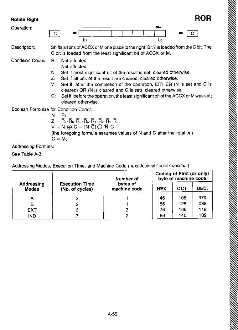
Rotate Right
Operation:
ROR
b7 bo
Description: Shifts all bits of ACCX Or M one place to the right. Bit 7 is loaded from the C bit. TheC bit is loaded from the least significant bit of ACCX or M.
Condition Codes: H: Not affected.I: Not affected.N: Set if most significant bit of the result is set; cleared otherwise.Z: Set if all bits of the result are cleared; cleared otherwise.V: Set if, after the completion of the operation, EITHER (N is set and C is
cleared) OR (N is cleared and C is set); cleared otherwise.C: Set if, before the operation, the least significant bit of the ACCX or M was set;
cleared otherwise.
Boolean Formulae for Condition Codes:N = R7Z = Fh·Rs·Rs·R4·i=b·R2·R1·RoV = N (f) C = [N·el 0 [N·Cl(the foregoing formula assumes values of Nand C after the rotation)C = Mo
Addressing Formats:
See Table A-3
Addressing Modes, Execution Time, and Machine Code (hexadecimal/ octal/ decimal):
Coding of First (or only)Number of byte of machine code
Addressing Execution Time bytes ofModes (No. of cycles) machine code HEX. OCT. DEC.
A 2 1 46 106 070B 2 1 56 126 086
EXT 6 3 76 166 118IND 7 2 66 146 102
A-55
I
IIIIIII

RTI Return from Interrupt
Operation: SP ~ (SP) + 0001 , fCCSP ~ (SP) + 0001 , fACCBSP ~ (SP) + 0001 , fACCASP ~ (SP) + 0001 , flXHSP ~ (SP) + 0001 , flXLSP ~ (SP) + 0001 , fPCHSP ~ (SP) + 0001 , fPCL
Description: The condition codes, accumulators B and A, the index register, and the programcounter, will be restored to a state pulled from the stack. Note that the interruptmask bit will be reset if and only if the corresponding bit stored in the stack is zero.
Condition Codes: Restored to the states pulled from the stack.
Addressing Modes, Execution Time, and Machine Code (hexadecimal/ octal/ decimal):
Coding of First (or only)Number of byte of machine code
Addressing Execution Time bytes ofModes (No. of cycles) machine code HEX. OCT. DEC.
INHERENT 10 1 3B 073 059
Return from Interrupt
Example
A. BeforePC ~
SP ~
MemoryLocation
$D066
$EFF8$EFF9$EFFA$EFFB$EFFC$EFFD$EFFE$EFFF
MachineCode (Hex)
3B
11HINZVC123456785567
Assembler LanguageLabel Operator Operand
RTI
(binary)
B. AfterPC ~ $5567
$EFF8$EFF9$EFFA$EFFB$EFFC$EFFD$EFFE
SP ~ $EFFFCC = HINZVC (binary)ACCB = 12 (Hex)ACCA = 34 (Hex)
**
11HINZVC123456785567
IXH = 56 (Hex)IXL = 78 (Hex)
A-56
(binary)
*** *****
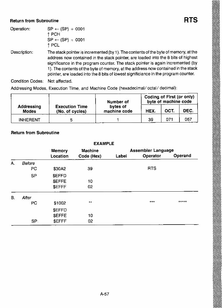
RTSReturn from Subroutine
Operation: SP ~ (SP) + 0001t PCHSP ~ (SP) + 0001t PCl
Description: The stack pointer is incremented (by 1). The contents of the byte of memory, at theaddress now contained in the stack pointer, are loaded into the 8 bits of highestsignificance in the program counter. The stack pointer is again incremented (by1). The contents of the byte of memory, at the address now contained in the stackpointer, are loaded into the 8 bits of lowest significiance in th~ program counter.
Condition Codes: Not affected.
Addressing Modes, Execution Time, and Machine Code (hexadecimal/ octal/ decimal):
Coding of First (or only)Number of byte of machine code
Addressing Execution Time bytes ofModes (No. of cycles) machine code HEX. OCT. DEC.
INHERENT 5 1 39 071 057
Return from Subroutine
EXAMPLE
Memory Machine Assembler LanguageLocation Code (Hex) Label Operator Operand
A. BeforePC $30A2 39 RTS
SP $EFFD$EFFE 10$EFFF 02
B. AfterPC $1002 ** *** *****
$EFFD$EFFE 10
SP. $EFFF 02
A-57

SBA Subtract Accumulators
Operation:
Description:
ACCA ~ (ACCA) - (ACCB)
Subtracts the contents of ACCB from the contents of ACCA and places the resultin ACCA. The contents of ACCB are not affected.
Condition Codes: H: Not affected.I: Not affected.N: Set if most significant bit of the result is set; cleared otherwise.Z: Set if all bits of the result are cleared; cleared otherwise.V: Set if there was two's complement overflow as a result of the operation.C: Carry is set if the absolute value of accumulator B plus previous carry is
larger than the absolute value of accumulator A; reset otherwise.
Boolean Formulae for Condition Codes:N = R7Z = i=h·R6·Rs·R4·R3·R2·R1·RoV = A7·B7·i=h+A7·B7·R7C = A7' B7+B7' R7+R7' A7
Addressing Modes, Execution Time, and Machine Code (hexadecimal/ octal/ decimal):
Coding of First (or only)Number of byte of machine code
Addressing Execution Time bytes ofModes (No. of cycles) machine code HEX. OCT. DEC.
INHERENT 2 1 10 020 016
A-58

Subtract with Carry SBCOperation:
Description:
ACCX ~ (ACCX) - (M) - (C)
Subtracts the contents. of M and C from the contents of ACCX and places theresult in ACCX,
Condition Codes: H: Not affected,I: Not affected,N: Set if most significant bit of the result is set; cleared otherwise,Z: Set if all bits of the result are cleared; cleared otherwise,V: Set if there was two's complement overflow as a result of the operation;
cleared otherwise,C: Carry is set if the absolute value of the contents of memory plus previous
carry is larger than the absolute value of the accumulator; reset otherwise,
Boolean Formulae for Condition Codes:N = R7Z = R7'R6'Rs'R4'Ra'R2'R1'RoV = X7·M7·R7+X7,M7,R7C = X7·M7+M7·R7+R7,X7
Addressing Formats:
See Table A-1.
Addressing Modes, Execution Time, and Machine Code (hexadecimal/ octal/ decimal):
(DUAL OPERAND)
Coding of First (or only)Number of byte of machine code
Addressing Execution Time bytes ofModes (No. of cycles) machine code HEX. OCT. DEC.
A IMM 2 2 82 202 130A 'DIR 3 2 92· 222 146A EXT 4 3 B2 262 178A IND 5 2 A2 242 162B IMM 2 2 C2 302 194B DIR 3 2 D2 322 210B EXT 4 3 F2 362 242B IND 5 2 E2 342 226
A-59

SECOperation: C bit ~ 1
Description: Sets the carry bit in the processor condition codes register.
Condition Codes: H: Not affected.I: Not affected.N: Not affected.Z: Not affected.V: Not affected.C: Set.
Boolean Formulae for Condition Codes:C = l'
Addressing Modes, Execution Time, and Machine Code (hexadecimal I octall decimal):
Set Carry
Coding of First (or only)Number of byte of machine code
Addressing Execution Time bytes ofModes (No. of cycles) machine code HEX. OCT. DEC.
INHERENT 2 1 00 015 013
A-60

Set Interrupt Mask SEIOperation; I bit ~ 1
Description: Sets the interrupt mask bit in the processor condition codes register. The microprocessor is inhibited from servicing an interrupt from a peripheral device, and willcontinue with execution of the instructions of the program, until the interrupt maskbit has been cleared.
Condition Codes: H: Not affected.I: Set.N: Not affected.z: Not affected.V: Not affected.C: Not affected.
Boolean Formulae for Condition Codes:I = 1
Addressing Modes, Execution Time, and Machine Code (hexadecimal! octal! decimal):
Coding of First (or only)Number of byte of machine code
Addressing Execution Time bytes ofModes (No. of cycles) machine code HEX. OCT. DEC.
INHERENT 2 1 OF 017 015
A-61

SEV Set Two's Complement Overflow Bit
Operation: V bit ~ 1
Description: Sets the two's complement overflow bit in the processor condition codes register.
Condition Codes: H: Not affected.I: Not affected.N: Not affected.z: Not affected.V: Set.C: Not affected.
Boolean Formulae for Condition Codes:V = 1
Addressing Modes, Execution Time, and Machine Code (hexadecimal/ octal/ decimal):
Coding of First (or only)Number of byte of machine code
Addressing Execution Time bytes ofModes (No. of cycles) machine code HEX. OCT. DEC.
INHERENT 2 1 OB 013 011
A-52

A-63
Addressing Modes, Execution Time, and Machine Code (hexadecimal/ octal/ decimal):
Addressing Formats:
See Table A-2.
STAStore Accumulator
Coding of First (or only)Number of byte of machine code
Addressing Execution Time bytes ofModes (No. of cycles) machine code HEX. OCT. DEC.
A DIR 4 2 97 227 151A EXT 5 3 B7 267 183A IND 6 2 A7 247 167B DIR 4 2 D7 327 215B EXT 5 3 F7 367 247B IND 6 2 E7 347 231
M ~ (ACCX)
Stores the contents of ACCX in memory. The contents of ACCX remains unchanged.
Condition Codes: H: Not affected.I: Not affected.N: Set if the most significant bit of the contents of ACCX is set; cleared
otherwise.z: Set if all bits of the contents of ACCX are cleared; cleared otherwise.V: Cleared.C: Not affected.
Boolean Formulae for Condition Codes:N = X7Z = X7' X6' Xs, X4' X3' X2' Xl' XoV = 0
Operation:
Description:

STS Store Stack Pointer
Operation: M ~ (SPH)M + 1 ~ (SPL)
Description: Stores the'more significant byte of the stack pointer in memory at the addressspecified by the program, and stores the less significant byte of the stack pointerat the next location in memory, at one plus the address specified by the program.
Condition Codes: H: Not affected.I: Not affected.N: Set if the most significant bit of the stack pointer is set; cleared otherwise.Z: Set if all bits of the stack pointer are cleared; cleared otherwise.V: Cleared.C: Not affected.
Boolean Formulae for Condition Codes:N = SPH7Z = (SPH7' SPH6' SPHs' SPH4' SPH3 . SPH2' SPH1 .SPHo)'
(SPL7' SPLs' SPLs' SPl4' SP13' SPL2' SPL1 .SPLo)V = 0
Addressing Formats:
See Table A-6.
Addressing Modes, Execution Time, and Machine Code (hexadecimal! octal/ decimal):
Coding of First (or only)Number of byte of machine code
Addressing Execution Time bytes ofModes (No. of cycles) machine code HEX. OCT. DEC.
DIR 5 2 9F 237 159EXT 6 3 BF 277 191IND 7 2 AF 257 175
A-64

Store Index Register STXOperation: M ~ (IXH)
M + 1 ~ (IXL)
Description: Stores the more significant byte of the index register in memory at the addressspecified by the program, and stores the less significant byte of the index registerat the next location in memory, at one plus the address specified by the program.
Condition Codes: H: Not affected.I: Not affected.N: Set if the most significant bite of the index register is set; cleared otherwise.z: Set if all bits of the index register are cleared; cleared otherwise.V: Cleared.C: Not affected.
Boolean Formulae for Condition Codes:N = IXH7Z = (IXH7 ·IXH6·IXHs ·IXH4 ·IXH3 . IXH2 ·IXHl ·IXHo)·
(IXL7·IXL6·IXLs·IXl4·IXL3·IXL2·IXL1·IXL0)V = 0
Addressing Formats:
See Table A-6.
Addressing Modes, Execution Time, and Machine Code (hexadecimal/ octal/ decimal):
Coding of First (or only)Number of byte of machine code
Addressing Execution Time bytes ofModes (No. of cycles) machine code HEX. OCT. DEC.
DIR 5 2 OF 337 223EXT 6 3 FF 377 255IND 7 2 EF 357 239
A-65
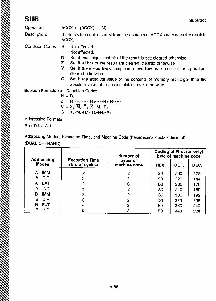
A-66
Addressing Modes, Execution Time, and Machine Code (hexadecimal/ octal/ decimal):
(DUAL OPERAND)
Coding of First (or only)Number of byte of machine code
Addressing Execution Time bytes ofModes (No. of cycles) machine code HEX. OCT. DEC.
A IMM 2 2 80 200 128A DIR 3 2 90 220 144A EXT 4 3 BO 260 176A IND 5 2 AO 240 160B IMM 2 2 CO 300 192B DIR 3 2 DO 320 208B EXT 4 3 FO 360 240B IND 5 2 EO 340 224
Subtract
Operation:
Description:
ACCX ~ (ACCX) - (M)
Subtracts the contents of M from the contents of ACCX and places the result inACCX.
Condition Codes: H: Not affected.I: Not affected.N: Set if most significant bit of the result is set; cleared otherwise.Z: Set if all bits of the result are cleared; cleared otherwise.V: Set if there was two's complement overflow as a result of the operation;
cleared otherwise.C: Set if the absolute value of the contents of memory are larger than the
absolute value of the accumulator; reset otherwise,
Boolean Formulae for Condition Codes:N = R7Z = R7·R6·Rs·R4·R3·R2·R1·RoV = X7·M7,R7'X7,M7,R7C = X7·M7+M7,R7+R7,X7
Addressing Formats:
See Table A-1.
SUB
~II
II
II
I

Coding of First (or only)Number of byte of machine code
Addressing Execution Time bytes ofModes (No. of cycles) machine code HEX. OCT. DEC.
INHERENT 12 1 3F 077 063
Software Interrupt SWIOperation: PC ~ (PC) + 0001
! (PCl) , SP ~ (SP)-0001! (PCH) , SP ~ (SP)-0001! (IXl) , SP ~ (SP)-0001! (IXH) , SP ~ (SP)-0001! (ACCA) , SP ~ (SP)-0001! (ACCB) , SP ~ (SP)-0001! (CC) , SP ~ (SP)-0001I ~1PCH ~ (n-0005)PCl ~ (n-0004)
Description: The program counter is incremented (by 1). The program counter, index register,and accumulator A and B, are pushed into the stack. The condition codes registeris then pushed into the stack, with condition codes H, I, N; Z, V, C goingrespectively into bit positions 5 thru 0, and the top two bits (in bit positions 7 and 6)are set (to the 1 state). The stack pointer is decremented (by 1) after each byte ofdata is stored in the stack.
The interrupt mask bit is then set. The program counter is then loaded with the ~
address stored in the software interrupt pointer at memory locations (n-5) and ~I~~.(n-4), where n is the address corresponding to a high state on all lines of the ~address bus.
Condition Codes: H: Not affected.I: Set.N: Not affected.Z: Not affected.V: Not affected.C: Not affected.
Boolean Formula for Condition Codes:I = 1
Addressing Modes, Execution Time, and Machine Code (hexadecimal! octal! decimal):
A-67
I

Software InterruptEXAMPLEA. Before:
CC = HINZVC (binary)ACCS = 12 (Hex)ACCA = 34 (Hex)
MemoryLocation
PC --'; $5566SP --'; $EFFF
$FFFA$FFFB
IXH = 56 (Hex)IXL = 78 (Hex)
MachineCode (Hex)
3F
DO55
Assembler LanguageLabel Operator Operand
SWI
III
B. After:PC --'; $0055SP --'; $EFF8
$EFF9 11 HINZVC (binary)$EFFA 12$EFFB 34$EFFC 56$EFFO 78$EFFE 55$EFFF 67
Note: This example assumes that FFFF is the memory location addressed when all lines of theaddress bus go to the high state.
A-68

Transfer from Accumulator A to Accumulator B TABOperation:
Description:
ACCS ~ (ACCA)
Moves the contents of ACCA to ACCS. The former contents of ACCS are lost.The contents of ACCA are not affected.
Condition Codes: H: Not affected.I: Not affected.N: Set if the most significant bit of the contents of the accumulator is set; cleared
otherwise.Z: Set if all bits of the contents of the accumulator are cleared; cleared other
wise.V: Cleared.C: Not affected.
Boolean Formulae for Condition Codes:N = R7Z = R7·R6·Rs·R4·R3·R2·R1·RoV = 0
Addressing Modes, Execution Time, and Machine Code (hexadecimal/ octal! decimal):
Coding of First (or only)Number of byte of machine code
Addressing Execution Time bytes ofModes (No. of cycles) machine code HEX. OCT. DEC.
INHERENT 2 1 16 026 022
A-69

TAP
Operation: CC ~ (ACCA)
Bit Positions
7 6 543 2 1 a
Transfer from Accumulator Ato Processor Condition Codes Register
ACCA
CC
Carry-Borrow
"""---- Overflow(Two's Complement)
"---- ZeroL.....- Negative
1-.- Interrupt Mask
L.....- Half Carry
Description: Transfers the contents of bit positions athru 5 of accumulator A to the corresponding bit positions of the processor condition codes register. The contents ofaccumulator A remain unchanged.
Condition Codes: Set or reset according to the contents of the respective bits athru 5 of accumulatorA.
Addressing Modes, Execution Time, and Machine Code (hexadecimal/ octal/ decimal):
Coding of First (or only)Number of byte of machine code
Addressing Execution Time bytes ofModes (No. of cycles) machine code HEX. OCT. DEC.
INHERENT 2 1 06 006 006
A-70

Transfer from Accumulator B to Accumulator A TBAOperation:
Description:
ACCA ~ (ACCS)
Moves the contents of ACCB to ACCA. The former contents of ACCA are lost.The contents of ACCB are not affected.
Condition Codes: H: Not affected.I: Not affected.N: Set if the most significant accumulator bit is set; cleared otherwise.z: Set if all accumulator bits are cleared; cleared otherwise.V: Cleared.C: Not affected.
Boolean Formulae for Condition Codes:N = R7Z = R7' A6·As· R4·R3·R2·A1·RoV = 0
Addressing Modes, Execution Time, and Machine Code (hexadecimal/ octall decimal):
Coding of First (or only)Number of byte of machine code
Addressing Execution Time bytes ofModes (No. of cycles) machine code HEX. OCT. DEC.
INHERENT 2 1 17 027 023
A-71

TPA
Operation:
Transfer from Processor Condition Codes Register toAccumulator A
ACCA ~ (CC)
Bit Positions
11 _--I
ACCA
CC
Carry-Borrow
L...-__ Overflow(Two's Complement)
'------- Zero
'-------- Negative
L..- Interrupt Mask
L.....-.. Half Carry
I
Description: Transfers the contents of the processor condition codes register to correspondingbit positions 0 thru 5 of accumulator A. Bit positions 6 and 7 of accumulator A areset (Le. go to the "1" state). The processor condition codes register remainsunchanged.
Condition Codes: Not affected.
Addressing Modes, Execution Time, and Machine Code (hexadecimal/ octal/ decimal):
Coding of First (or only)Number of byte of machine code
Addressing Execution Time bytes ofModes (No. of cycles) machine code HEX. OCT. DEC.
INHERENT 2 1 07 007 007
A-72

Test TSTOperation: (ACCX) - 00
(M) - 00
Description: Set condition codes Nand Z according to the contents of ACCX or M.
Condition Codes: H: Not affected.I: Not affected.N: Set if most significant bit of the contents of ACCX or M is set; cleared
otherwise.Z: Set if all bits of the contents of ACCX or M are cleared; cleared otherwise.V: Cleared.C: Cleared.
Boolean Formulae for Condition Codes:N = M7Z = M7·M6·Ms·M4·M3·M2·M1·MoV = 0C =0
Addressing Formats:
See Table A-3.
Addressing Modes, Execution Time, and Machine Code (hexadecimal/ octal/ decimal):
Coding of First (or only)Number of byte of machine code
Addressing Execution Time bytes ofModes (No. of cycles) machine code HEX. OCT. DEC.
A 2 1 40 115 077B 2 1 50 135 093
EXT 6 3 70 175 125INO 7 2 60 155 109
A-73
I

TSX Transfer from Stack Pointer to Index Register
Operation: IX ~ (SP) + 0001
Description: Loads the index register with one plus the contents of the stack pointer. Thecontents of the stack pointer remain unchanged.
Condition Codes: Not affected.
Addressing Modes, Execution Time, and Machine Code (hexadecimal/ octal/ decimal):
Coding of First (or only)Number of byte of machine code
Addressing Execution Time bytes ofModes (No. of cycles) machine code HEX. OCT. DEC.
INHERENT 4 1 30 060 048
A-74
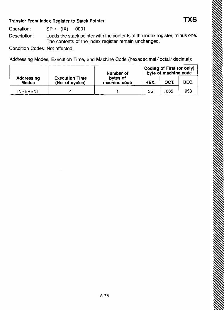
Coding of First (or only)Number of byte of machine code
Addressing Execution Time bytes ofModes (No. of cycles) machine code HEX. OCT. DEC.
INHERENT 4 1 35 .065 053
Transfer From Index Register to Stack Pointer TXSOperation: SP ~ (IX) - 0001
Description: Loads the stack pointer with the contents of the index register, minus one.The contents of the index register remain unchanged.
Condition Codes: Not affected.
Addressing Modes, Execution Time, and Machine Code (hexadecimal/ octal/ decimal):
IA-75

A-76
Coding of First (or only)Number of byte of machine code
Addressing Execution Time bytes ofModes (No. of cycles) machine code HEX. OCT. DEC.
INHERENT 9 1 3E 076 062
Operation: PC ~ (PC) + 0001! (PCl) , SP ~ (SP)-0001! (PCH) , SP ~ (SP)-0001! (IXl) , SP ~ (SP)-0001! (IXH) , SP ~ (SP)-0001! (ACCA) , SP ~ (SP)-0001! (ACCS) , SP ~ (SP)-0001! (CC) , SP ~ (SP)-0001
Condition Codes: Not affected.
Description: The program counter is incremented (by 1). The program counter, index register,and accumulators A and B, are pushed into the stack. The condition codesregister is then pushed into the stack, with condition codes H, I, N, Z, V, C goingrespectively into bit positions 5 thru 0, and the top two bits (in bit positions 7 and 6)are set (to the 1 state). The stack pointer is decremented (by 1) after each byte ofdata is stored in the stack.
Execution of the program is then suspended until an interrupt from a peripheraldevice is signalled, by the interrupt request control input going to a low state.
When an interrupt is signalled on the interrupt request line, and provided the I bit isclear, execution proceeds as follows. The interrupt mask bit is set. The programcounter is then loaded with the address stored in the internal interrupt pointer atme.mory locations (n-7) and (n-6), where n is the address corresponding to a highstate on all lines of the address bus.
Condition Codes: H: Not affected.I: Not affected until an interrupt request signal is detected on the interrupt
request control line. When the interrupt request is received the I bit is set andfurther execution takes place, provided the I bit was initially clear.
N: Not affected.Z: Not affected.V: Not affected.C: Not affected.
Addressing Modes, Execution Time, and Machine Code (hexadecimal/ octal/ decimal):
~
I
I
WAI Wait for Interrupt

Addressing Mode of First Operand
Second Operand Accumulator A Accumulator B
IMMediate eee A #number eee B #numbereee A #symbol eee B #symboleee A #expression eee B #expressioneee A #te eee B #te
DIRect or EXTended eee A number eee B numbereee A symbol eee B symboleee A expression eee B expression
INDexed eeeAX eee BXeee z ,X eee B ,Xeee A number,X eee B number,Xeee A symbol,X eee B symbol,Xeee A expression,X eee B expression,X
Notes: 1. eee = mnemonic operator of source instruction.2. "symbol" may be the special symbol "*".3. "expression" may contain the special symbol "*".4. space may be omitted before A or B.
Applicable to the following source instructions:ADe ADD AND BIT eMPEOR LOA ORA SBe SUB
*Special symbol indicating program-counter.
TABLE A-1. Addressing Formats (1)
Addressing Mode of First OperandSecond Operand Accumulator A Accumulator B
DIRect or EXTended STA A number STA B numberSTA A symbol STA B symbolSTA A expression STAB expression
INDexed STAAX STA BXSTA A ,X STA B ,XSTA A number,X STA B number,XSTA A symbol,X STA B symbol,XSTA A expression,X STA B expression,X
Notes: 1. "symbol" may be the special symbol "*".2. "expression" may contain the special symbol "*".3. Space may be omitted before A or B.
Applicable to the source instruction:
STA
*Special symbol indicating program-counter.
TABLE A-2. Addressing Formats (2)
A-77
IIII
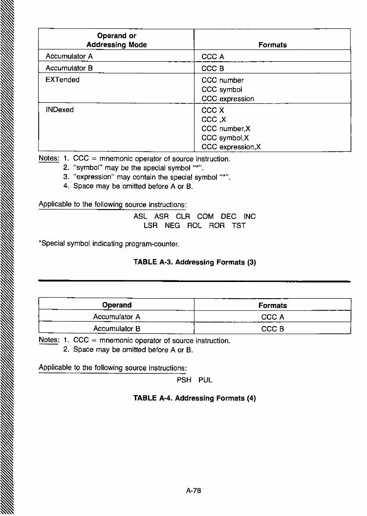
Operand orAddressing Mode Formats
Accumulator A eeeA
Accumulator B eee B
EXTended eee numbereee symboleee expression
INDexed eeexeee,xeee number,Xeee symbol,Xeee expression,X
Notes: 1. eee = mnemonic operator of source instruction.2. "symbol" may be the special symbol u*".3. "expression" may contain the special symbol "*".4. Space may be omitted before A or B.
Applicable to the following source instructions:
ASL ASR eLR eOM DEe INeLSR NEG ROL ROR TST
*Special symbol indicating program-counter.
TABLE A·3. Addressing Formats (3)
Operand Formats
Accumulator A eeeA
Accumulator B eeeB
Notes: 1. eee = mnemonic operator of source instruction.2. Space may be omitted before A or B.
Applicable to the following source instructions:
PSH PUL
TABLE A-4. Addressing Formats (4)
A-78

Addressing Mode Formats
IMMediate eee #numbereee #symboleee #expressioneee #'e
DIRect or EXTended eee numbereee symboleee expression
INDexed eeexeee ,Xeee number,Xeee symbol,Xeee expression,X
Notes: 1. eee = mnemonic operator of source instruction.2. "symbol" may be the special symbol "*".3. "expression" may contain the special symbol "*".
Applicable to the following source instructions:
epx LOS LOX
*Special symbol indicating program-counter.
TABLE A-5. Addressing Formats (5)
Addressing Mode Formats
DIRect or EXTended eee numbereee symboleee expression
INDexed eeexeee,xeee number,Xeee symbol,Xeee expression,X
Notes: 1. eee = mnemonic operator of source instruction.2. "symbol" may be the special symbol "*".3. "expression" may contain the special symbol "*".
Applicable to the following source instructions:
STS STX
*Special symbol indicating program-counter.
TABLE A-6. Addressing Formats (6)
A-79
I

Addressing Mode Formats
EXTended eee numbereee symboleee expression
INDexed eeexeee,xeee number,Xeee symbol,Xeee expression,X
Notes: 1. eee = mnemonic operator of source instruction.2. "symbol" may be the special symbol "*".3. "expression" may contain the special symbol "*".
Applicable to the following source instructions:
JMP JSR
*Special symbol indicating program-counter.
TABLE A-7. Addressing Formats (7)
Addressing Mode Formats
RElative eee numbereee symboleee expression
Notes: 1. eee = mnemonic operator of source instruction.2. "symbol" may be the special symbol "*".3. "expression" may contain the special symbol "*".
Applicable to the following source instructions:
Bee Bes BEQ BGE BGT BHI BlE BlSBlT BMI BNE BPl BRA BSR Bve BVS
*Special symbol indicating program-counter.
TABLE A-8. Addressing Formats (8)
A-SO

EXbug COMMANDS
LOAD
VERF
PNCH
PRNT
SRCH
S10, S30, & S120
S240(EXbug 1.2 only)
TERM(EXbug 1.2 only)
MAID
n/
n;O
(LF)
t
APPENDIX BEXbug COMMANDS
DESCRIPTION
Initiates memory loader function.
Compares contents of memory with tape data. Where unequal, printslocation in hexadecimal.
Instructs EXORciser to punch an absolute formatted binary objecttape.
Causes terminal to print the contents of memory in hexadecimalfollowed by the literal ASCII characters.
Searches tape for header record. Stops reader at first recordencountered and prints that record.
Inserts nulls for proper printing during terminal operation at 110,300, and 1200 Baud: 8, or 8, or 3 nulls, respectively, inserted afterstandard ASCII characters; 8, or 4, or 23, respectively, insertedfollowing carriage return character.
Inserts nulls for proper printing during 2400 Baud terminal operation. Seven nulls inserted after standard ASCII characters; 47 nullsinserted following carriage return character.
Prints the number of nulls currently being inserted after standardASCII and carriage return characters. Permits either or both tobe changed.
Print the contents of memory location n and enable the EXORciserto change the contents of this memory location.
Calculate the address offset (for relative addressing modeinstructions.
Print the contents of the next sequential memory location andenable the EXORciser to change the contents of this memorylocation (LF - Line Feed character).
Print the contents of the previous sequential memory locationand enable the EXORciser to change the contents of thismemory location (t - up arrow character, or SHIFT key, or Ncharacter).
B-1

EXbug COMMANDS
(CR)
n;V
$V
n;P
;U
n;U
n;W
$M
;G
n;G
$R
;P
;N
N
n;N
$T
;T
$S
;S
#n=
#$n=
#@n=
DESCRIPTION
Return the displayed contents to memory and accept nextcommand (CR - Carriage Return character).
Enter a breakpoint at memory location n.
Display the memory location of each breakpoint.
Continue executing from the selected breakpoint until this breakpoint is encountered n times.
Remove all the breakpoints.
Remove the breakpoint at memory location n.
Search for the n bit pattern.
Display the search mask.
Execute the user's program starting at the auto restart memorylocation.
Execute user's program starting at memory location n.
Display/ change the user's program registers.
Continue executing from the current program counter setting.
Trace one instruction.
Trace one instruction.
Trace n instructions.
Set the trace mode.
Reset the trace mode.
Display and set the stop-on-address compare - Scope triggerpulse.
Reset the stop-on-address compare - Scope trigger pulse.
Convert the decimal number n to its hexadecimal equivalent.
Convert the hexadecimal number n to its decimal equivalent.
Convert the octal number n to its hexadecimal equivalent.
B-2

APPENDIX CMIKbug COMMANDS
OPERATION DESCRIPTION
L Load tape.M Memory change.R Display registers CC, B, A, X, P, S.P Print! punch tape.G Go to location.
C-1

C-2

APPENDIX DMINlbug II COMMANDS
COMMAND DESCRIPTION
L Load tape.
M Memory Change.
P Print/ punch dump.
R Display registers CC, B, A, X, P, S.
S Set terminal speed:1 - set speed for 10 cps3 - set speed for 30 cps
G Go to location nnnn.
W Memory test.
y Punch binary tape.
Z Load binary tape.
See Evaluation Module II User's Guide for detailed description.
D-1

0-2
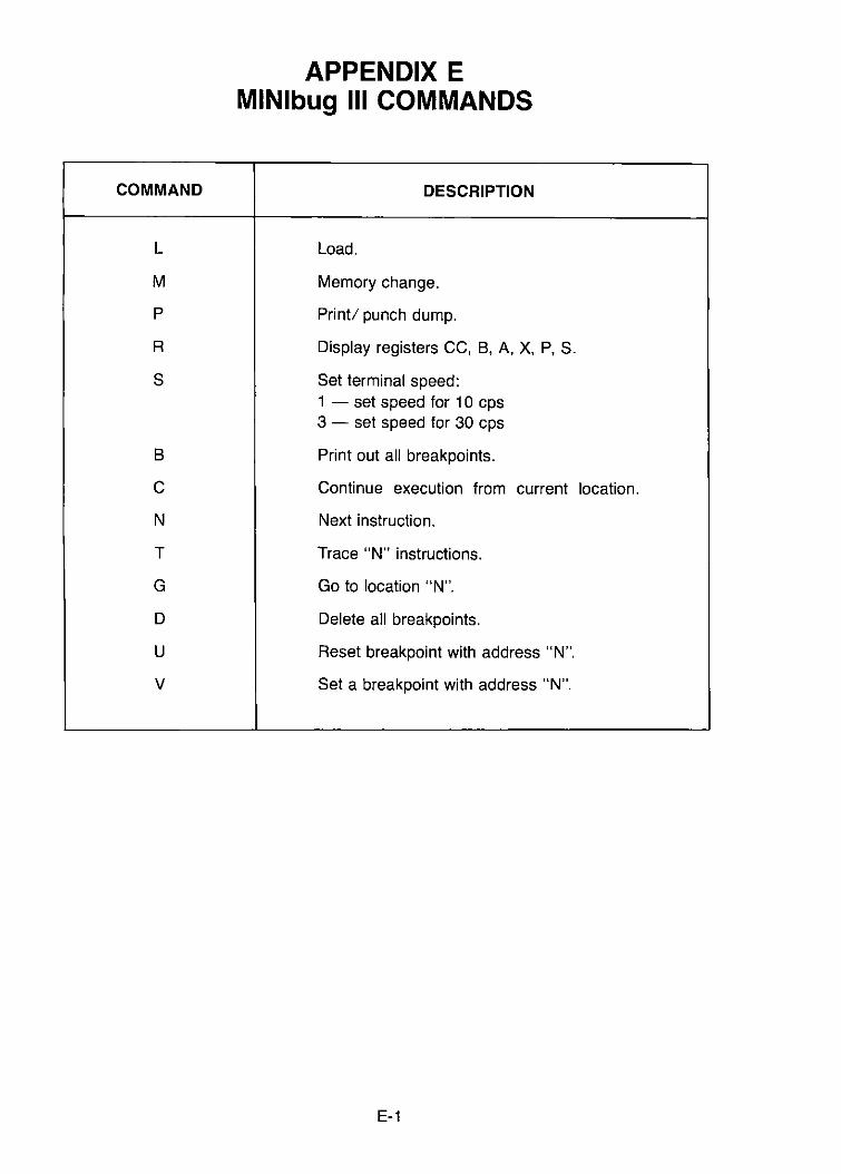
COMMAND
L
M
P
R
S
8
C
N
T
G
D
U
V
APPENDIX EMINlbug III COMMANDS
DESCRIPTION
Load.
Memory change.
Print/ punch dump.
Display registers CC, 8, A, X, P, S.
Set terminal speed:1 - set speed for 10 cps3 - set speed for 30 cps
Print out all breakpoints.
Continue execution from current location.
Next instruction.
Trace "N" instructions.
Go to location "N tt•
Delete all breakpoints.
Reset breakpoint with address "N".
Set a breakpoint with address "N".
E-1

E-2
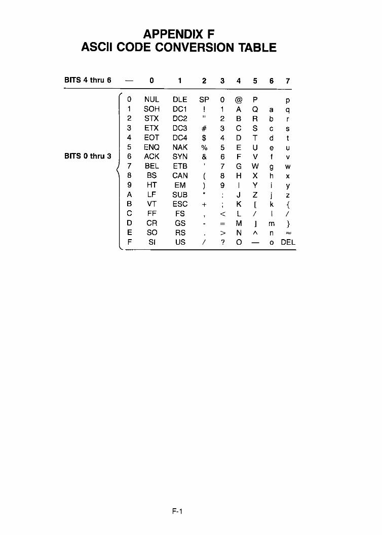
APPENDIX FASCII CODE CONVERSION TABLE
BITS 4 thru 6 0 1 2 3 4 5 6 7
0 NUL OLE SP 0 @ P P1 SOH OC1 ! 1 A Q a q2 STX OC2 " 2 B R b r3 ETX OC3 # 3 C S c s4 EOT OC4 $ 4 0 T d t5 ENQ NAK 0/0 5 E U e u
BITS 0 thru 3 6 ACK SYN & 6 F V f v7 BEL ETB 7 G W 9 w8 BS CAN ( 8 H X h x9 HT EM ) 9 I Y YA LF SUB * J Z j zB VT ESC + K [ k {C FF FS < L / I /0 CR GS = M ] m }E SO RS > N " n ::::::::
F SI US / ? 0 0 DEL
F-1

F-2

APPENDIX GHEXADECIMAL AND DECIMAL CONVERSION
From hex: locate each hex digit in its corresponding column position and note the decimalequivalents. Add these to obtain the decimal value.
From decimal: (1) locate the largest decimal value in the table that will fit into the decimalnumber to be converted, and (2) note its hex equivalent and hex column position. (3) Findthe decimal remainder. Repeat the process on this and subsequent remainders.
HEXADECIMAL COLUMNS
6 5 4 3 2 1
HEX = DEC HEX = DEC HEX = DEC HEX = DEC HEX = DEC HEX = DEC
° ° ° ° ° ° ° ° ° ° ° °1 1,048,576 1 65,536 1 4,096 1 256 1 16 1 12 2,097,152 2 131,072 2 8,192 2 512 2 32 2 23 3,145,728 3 196,608 3 12,288 3 768 3 48 3 34 4,194,304 4 262,144 4 16,384 4 1,024 4 64 4 45 5,242,880 5 327,680 5 20,480 5 1,280 5 80 5 56 6,291,456 6 393,216 6 24,576 6 1,536 6 96 6 67 7,340,032 7 458,752 7 28,672 7 1,792 7 112 7 78 8,388,608 8 524,288 8 32,768 8 2,048 8 128 8 89 9,437,184 9 589,824 9 36,864 9 2,304 9 144 9 9A 10,485,760 A 655,360 A 40,960 A 2,560 A 160 A 10B 11 ,534;,336 B 720,896 B 45,056 B 2,816 B 176 B 11C 12,582,912 C 786,432 C 49,152 C 3,072 C 192 C 120 13,631,488 0 851,968 0 53,248 0 3,328 0 208 0 13E 14,680,064 E 917,504 E 54,344 E 3,584 E 224 E 14F 15,728,640 F 983,040 F 61,440 F 3,840 F 240 F 15
o 1 2 3 4 567 o 1 2 3 4 567 o 1 2 3 4 567
BYTE BYTE BYTE
G-1

POWERS OF 2
2n n
256 8512 9
1 024 102048 114096 128 192 13
16384 1432768 1565536 16
131 072 17.262 144 18
524288 191 048 576 202097 152 214 194304 228388 608 23
16777 216 24
20 = 160
24 = 16'28 = 162
2'2 = 163
2'8 = 164
220 = 165
224 = 166
228 = 167
232 = 168
238 = 169
240 = 16'0
244 = 16"248 = 16'2
252 = 16'3
256 = 16'4
260 = 16'5
G-2
POWERS OF 16
16n n
1 016 1
256 24096 3
65536 41 048576 5
16 777216 6268435456 7
4294967296 868 719 476 736 9
1 099 511 627 776 1017 592 186 044 416 11
281 474 976 710 656 124 503 599 627 370 496 13
72 057 594 037 927 936 141 152 921 504 606 846 976 15


•


MOTOROLA Semiconductor Products Inc.'.0.•OK 20912. 'HOl<NIK. "'''''ZON''' .5036 .... SU.510'''''''Y OF UOTO"'OL ... INC
M68PRM(OI _.--_.-_.......... -