Embed Size (px)
Citation preview
M7+ Display Installation Guide
PB11401Rev. 1A
Legal Notices
The information contained in this document is subject to change without notice.
DATA911 MAKES NO WARRANTY OF ANY KIND WITH REGARD TO THIS MATERIAL, INCLUDING, BUT NOT LIMITED TO, THE IMPLIED WARRANTIES OF MERCHANTABILITY AND FITNESS FOR A PARTICULAR PURPOSE. Data911 shall not be liable for errors contained herein or for incidental or consequential damages in connection with the furnishing, performance, or use of this material.
Data911 assumes no responsibility for the use or reliability of its software on equipment that is not furnished by Data911.
Copyright
© 2015 Data911. All rights reserved. No part of this document may be copied, photocopied, reproduced, translated, or reduced to any electronic medium or machine-readable form without prior written consent from Data911. Printed in the United States of America.
Trademarks
Data911 is a registered trademark of Data911, a Division of Hubb Systems LLC. Windows is a registered trademark of Microsoft Corporation in the United States and other countries. All other brand names used in this document are trademarks of their respective holders.
Company Information
Data911 Systems2021 Challenger DriveAlameda, CA 94501
www.data911.com
phone 510.865.9100fax 510.865.9090
Table of ContentsChapter 1 – Introducing the M7+ Display . . . . . . . . . . . . . . . . . . . . . . . . . . . . . . . . .1
About the M7+ Display . . . . . . . . . . . . . . . . . . . . . . . . . . . . . . . . . . . . . . . . . . . . . . . . . . . 2M7+ Display Features . . . . . . . . . . . . . . . . . . . . . . . . . . . . . . . . . . . . . . . . . . . . . . . . . 2
Contacting Data911 . . . . . . . . . . . . . . . . . . . . . . . . . . . . . . . . . . . . . . . . . . . . . . . . . . . . . 3
Chapter 2 – M7+ Display Installation . . . . . . . . . . . . . . . . . . . . . . . . . . . . . . . . . . . . .5M7+ Display Materials . . . . . . . . . . . . . . . . . . . . . . . . . . . . . . . . . . . . . . . . . . . . . . . . . . . 6
Installation Preparation . . . . . . . . . . . . . . . . . . . . . . . . . . . . . . . . . . . . . . . . . . . . . . . . . . 7Selecting a Location for the Display . . . . . . . . . . . . . . . . . . . . . . . . . . . . . . . . . . . . . . 7Cable Routing and Preparation . . . . . . . . . . . . . . . . . . . . . . . . . . . . . . . . . . . . . . . . . . 7
Installing the M7+ Display . . . . . . . . . . . . . . . . . . . . . . . . . . . . . . . . . . . . . . . . . . . . . . . . 8Connecting the Display to the Keyboard . . . . . . . . . . . . . . . . . . . . . . . . . . . . . . . . . . . 9Connecting the M7+ Display to the M7 Processor . . . . . . . . . . . . . . . . . . . . . . . . . . . 10
Replacing an M7 Display with an M7+ Display . . . . . . . . . . . . . . . . . . . . . . . . . . . . . . . . 12
Chapter 3 – Configuring the M7+ Display . . . . . . . . . . . . . . . . . . . . . . . . . . . . . . . .13Launching MDC Manager . . . . . . . . . . . . . . . . . . . . . . . . . . . . . . . . . . . . . . . . . . . . . . . . 14
Setting and Changing the MDC Manager Password . . . . . . . . . . . . . . . . . . . . . . . . . . . . . 15
Configuring the M7+ Display Settings and Controls . . . . . . . . . . . . . . . . . . . . . . . . . . . . 16Changing Display Settings . . . . . . . . . . . . . . . . . . . . . . . . . . . . . . . . . . . . . . . . . . . . 17Available Knob and Button Controls . . . . . . . . . . . . . . . . . . . . . . . . . . . . . . . . . . . . . 19Setting Actions for Display Buttons and Knob Press: Basic Steps . . . . . . . . . . . . . . . 19Setting the Knob Turning Controls . . . . . . . . . . . . . . . . . . . . . . . . . . . . . . . . . . . . . . 27Changing the Background LED Color . . . . . . . . . . . . . . . . . . . . . . . . . . . . . . . . . . . . 28
Working with Multiple Displays . . . . . . . . . . . . . . . . . . . . . . . . . . . . . . . . . . . . . . . . . . . 29Dual Display Touch Configuration . . . . . . . . . . . . . . . . . . . . . . . . . . . . . . . . . . . . . . 30
Reflashing the M7+ Display Firmware . . . . . . . . . . . . . . . . . . . . . . . . . . . . . . . . . . . . . . . 31
PB11401 iRev. 1A

Table of Contents M7+ Display Installation Guide
ii PB11401 Rev. 1A
Introducing the M7+ Display
C H A P T E R 1
This chapter describes the M7+ Display and tells you how to get in touch with Data911 if you need assistance. Information is organized in the following topics:About the M7+ Display, on page 2– M7+ Display Features, on page 2
Contacting Data911, on page 3
For additional information about installing and configuring the display, see:
• Chapter 2, "M7+ Display Installation" on page 5
• Chapter 3, "Configuring the M7+ Display" on page 13
PB11401 1Rev. 1A
Ch. 1 Introducing the M7+ DisplayAbout the M7+ Display M7+ Display Installation Guide
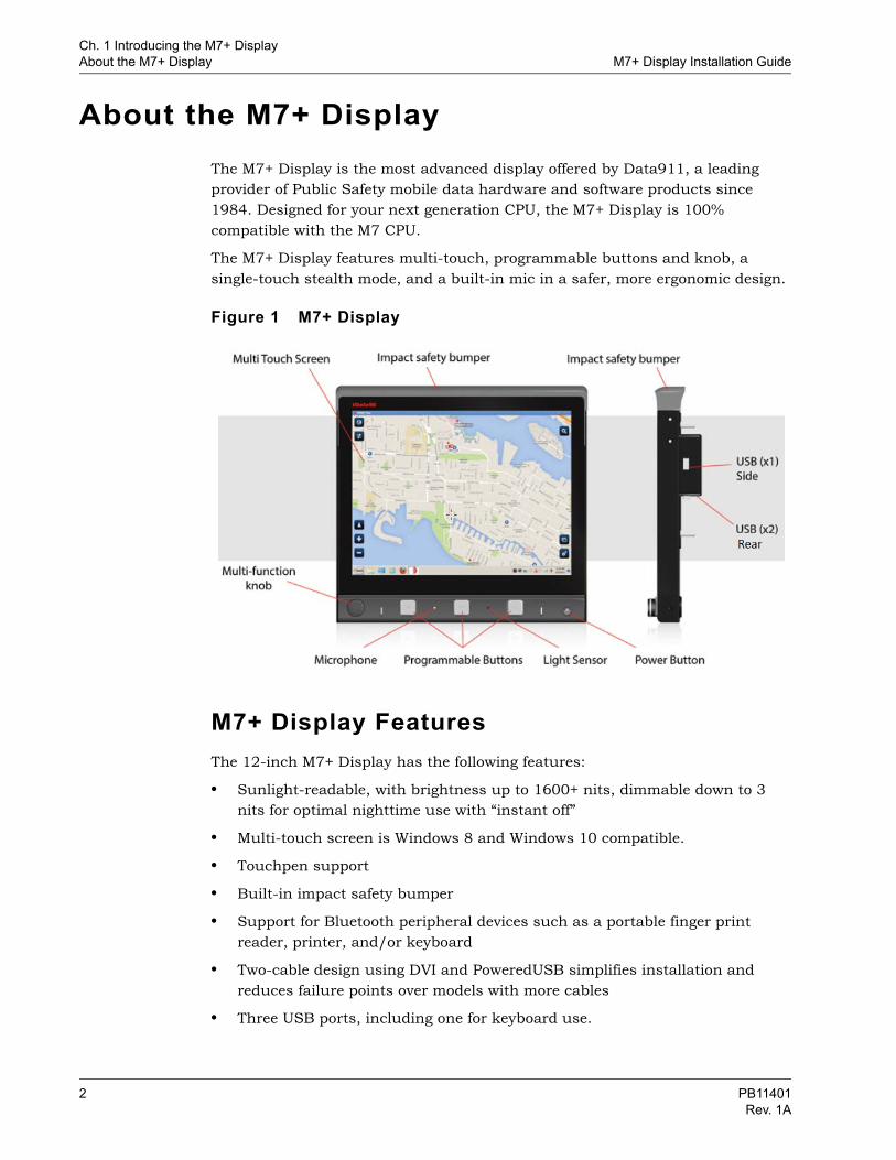
About the M7+ DisplayThe M7+ Display is the most advanced display offered by Data911, a leading provider of Public Safety mobile data hardware and software products since 1984. Designed for your next generation CPU, the M7+ Display is 100% compatible with the M7 CPU.
The M7+ Display features multi-touch, programmable buttons and knob, a single-touch stealth mode, and a built-in mic in a safer, more ergonomic design.
Figure 1 M7+ Display
M7+ Display FeaturesThe 12-inch M7+ Display has the following features:
• Sunlight-readable, with brightness up to 1600+ nits, dimmable down to 3 nits for optimal nighttime use with “instant off”
• Multi-touch screen is Windows 8 and Windows 10 compatible.
• Touchpen support
• Built-in impact safety bumper
• Support for Bluetooth peripheral devices such as a portable finger print reader, printer, and/or keyboard
• Two-cable design using DVI and PoweredUSB simplifies installation and reduces failure points over models with more cables
• Three USB ports, including one for keyboard use.
2 PB11401Rev. 1A
Ch. 1 Introducing the M7+ DisplayM7+ Display Installation Guide Contacting Data911
• Built-in microphone and ambient light sensor
• Built-in thermal protection
• Low power LED backlight
• Fanless design
• Chemically strengthened touch glass
• Stereo speakers
• Supports Windows 8 and Windows 10 requirements
Programmable controls give users quick access to important features:
• Stealth mode (full blackout) with a single touch for police vehicles
• Three programmable, backlit buttons. (Common actions include launching applications, stealth mode, blanking the screen, muting speakers, volume up adjustment, and brightness adjustment)
• Multi-function knob can be set to adjust volume, brightness, or scrolling
• Press of knob can be programmed to the same range of actions as the programmable buttons
Contacting Data911If for any reason you suspect a malfunction in the hardware of the M7+ Display, you may contact Data911 for additional support and assistance with the problem.
Hardware Service Department email: [email protected]
Hardware support: (510) 865-9100 x125
Fax: (510) 749-1443
Support website: http://www.data911.com/hwsupport
The support website includes details about equipment options and documents that may assist in the installation task.
For access to the support site, contact Data911 to obtain a login code.
Before contacting the Hardware Service Department for support or repair, gather as much information about the problem to assist in a proper diagnosis. Support technicians require serial number, part number, and a detailed description of the problem to provide service.
PB11401 3Rev. 1A

Ch. 1 Introducing the M7+ DisplayContacting Data911 M7+ Display Installation Guide
This page intentionally left blank
4 PB11401Rev. 1A
M7+ Display Installation
C H A P T E R 2
The information in this chapter summarizes materials you will need and basic steps to install an M7+ Display for use with an in-vehicle computer. It is organized under the following topics:M7+ Display Materials, on page 6
Installation Preparation, on page 7– Selecting a Location for the Display, on page 7– Cable Routing and Preparation, on page 7
Installing the M7+ Display, on page 8– Connecting the Display to the Keyboard, on page 9– Connecting the M7+ Display to the M7 Processor, on page 10
Replacing an M7 Display with an M7+ Display, on page 12
After the M7+ Display has been installed, you will want to configure the programmable buttons and knob. For details, turn to Configuring the M7+ Display, on page 13.
Important: To connect the M7+ display with a non-Data911 computer or tablet, you will need a Data911 Mobile Display Interface (MDI).
Note: If you are installing the M7+ Display as part of the M7 system package, you can follow the instructions for installing the M7 12” Display in the M7 Installation and Operation manual, and refer to the images on page 9 for minor changes to keyboard connection (the M7+ includes an additional USB port.)
PB11401 5Rev. 1A
Ch. 2 M7+ Display InstallationM7+ Display Materials M7+ Display Installation Guide
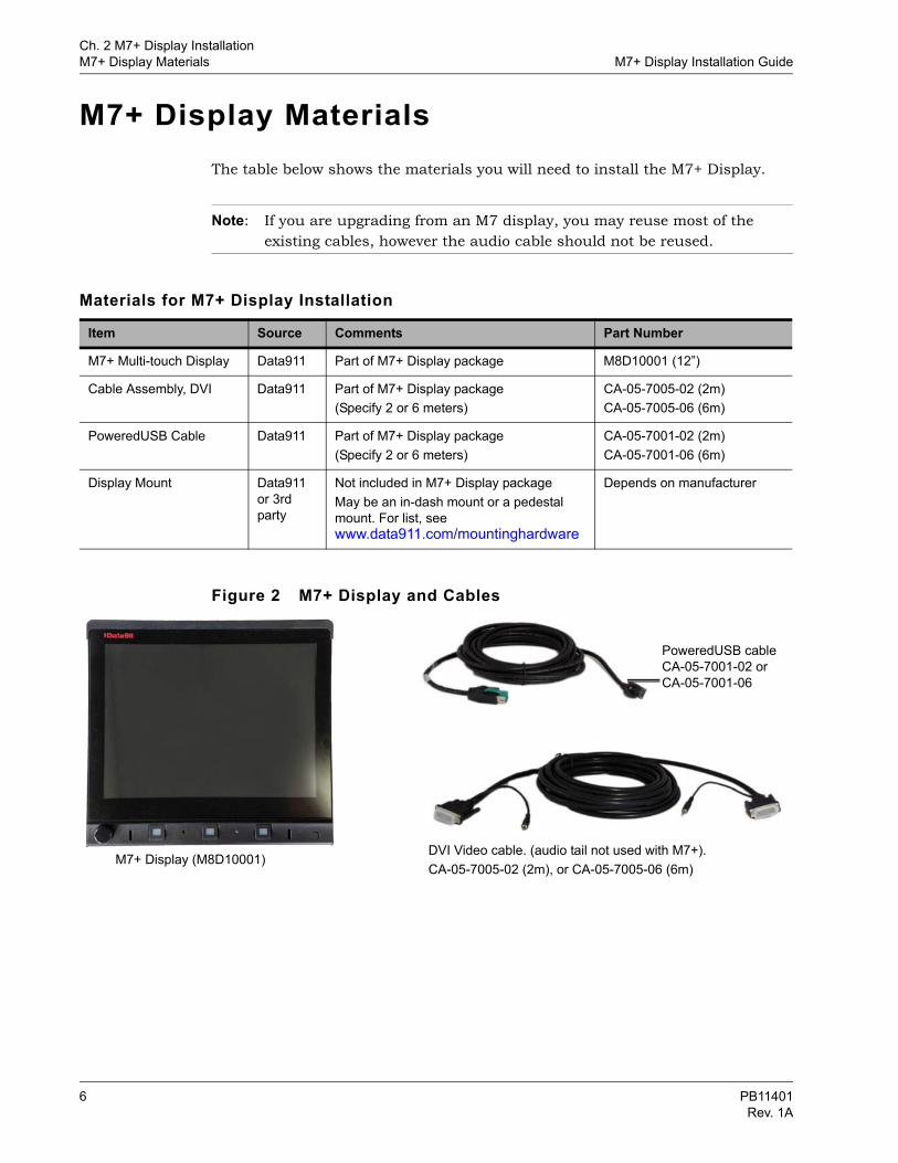
M7+ Display MaterialsThe table below shows the materials you will need to install the M7+ Display.
Note: If you are upgrading from an M7 display, you may reuse most of the existing cables, however the audio cable should not be reused.
Figure 2 M7+ Display and Cables
Materials for M7+ Display Installation
Item Source Comments Part Number
M7+ Multi-touch Display Data911 Part of M7+ Display package M8D10001 (12”)
Cable Assembly, DVI Data911 Part of M7+ Display package(Specify 2 or 6 meters)
CA-05-7005-02 (2m) CA-05-7005-06 (6m)
PoweredUSB Cable Data911 Part of M7+ Display package(Specify 2 or 6 meters)
CA-05-7001-02 (2m)CA-05-7001-06 (6m)
Display Mount Data911 or 3rd party
Not included in M7+ Display packageMay be an in-dash mount or a pedestal mount. For list, see www.data911.com/mountinghardware
Depends on manufacturer
M7+ Display (M8D10001) DVI Video cable. (audio tail not used with M7+).CA-05-7005-02 (2m), or CA-05-7005-06 (6m)
PoweredUSB cableCA-05-7001-02 orCA-05-7001-06
6 PB11401Rev. 1A
Ch. 2 M7+ Display InstallationM7+ Display Installation Guide Installation Preparation
Installation PreparationAs you’re getting ready to install the M7+ Display, you will want to consider where to locate it, and plan how you will route the cables.
Selecting a Location for the DisplayThe M7+ Display has a wide viewing angle, so it is not necessary to position it directly in front of the user. However, it is a good idea to keep the Display within reach of the user since it is equipped with a touch screen interface. You will also want to consider where to place the keyboard, within the user’s reach.
Exact placement will depend on the mount you select and on airbag deployment and other safety concerns.
Cable Routing and PreparationRoute the cables for the M7+ Display through the car so that it can connect to the Processor. The routing will vary, depending on where you place the Processor.
• When routing the cable between the M7+ Display and the Processor, make sure to leave enough slack, or service length, for any movement of the display that the third party mounts may allow.
• When routing cables between the M7+ Display and Keyboard, make sure any cables in the seating areas are tied and secured properly so as to not be damaged by passengers.
• If the M7+ Display cable is bundled into a harness with other cables and it will move, use strain relief to hold it in place and prevent strain on the connector.
• The M7+ does not use the audio tail attached to the DVI cable. Tape or clip the audio tail to the DVI cable to ensure it stays out of the way and does not snag on anything.
PB11401 7Rev. 1A
Ch. 2 M7+ Display InstallationInstalling the M7+ Display M7+ Display Installation Guide
Installing the M7+ DisplayA number of different aftermarket mounts are available to support the installation of the M7+ Display. They can be viewed on the Data911 hardware web site (http://www.data911.com/mountinghardware). Manufacturer’s installation instructions come with each mount.
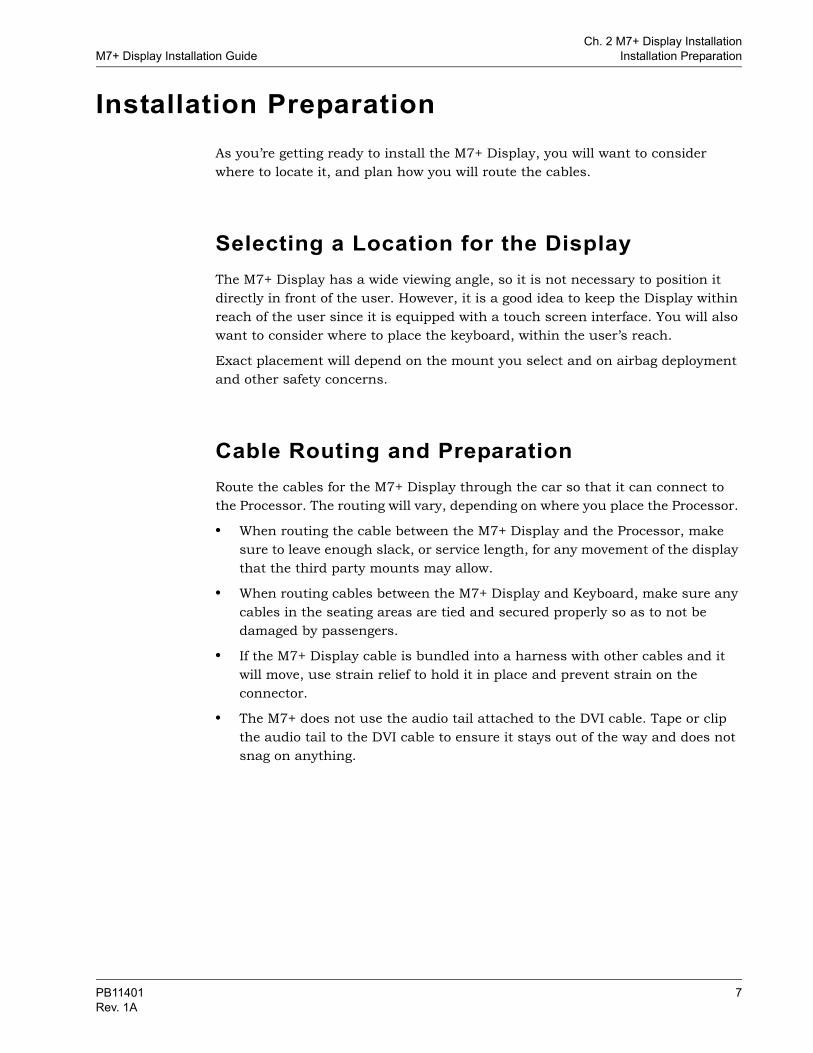
You connect the M7+ Display to a mount using the installation studs on the back of the display (Figure 3). The exact steps for connecting the M7+ Display to the mount will vary, depending on the mount.
Figure 3 Rear of M7+ Display
As you follow the installation instructions that come with the mount, keep the following in mind:
• Make sure that the display mount does not block the air intake near the bottom on the back of the M7+ Display.
• Make sure the rear USB ports are accessible.
• The M7+ Display must attach to the mount using all four ¼-20 studs on the back of the unit. The mount attaches with the nylock nuts provided with the system. Torque the nuts to 5.65 Nm (50 in-lb.). Do not over-tighten these nuts.
Installation studs are provided on the back of the M7+ Display
8 PB11401Rev. 1A
Ch. 2 M7+ Display InstallationM7+ Display Installation Guide Installing the M7+ Display
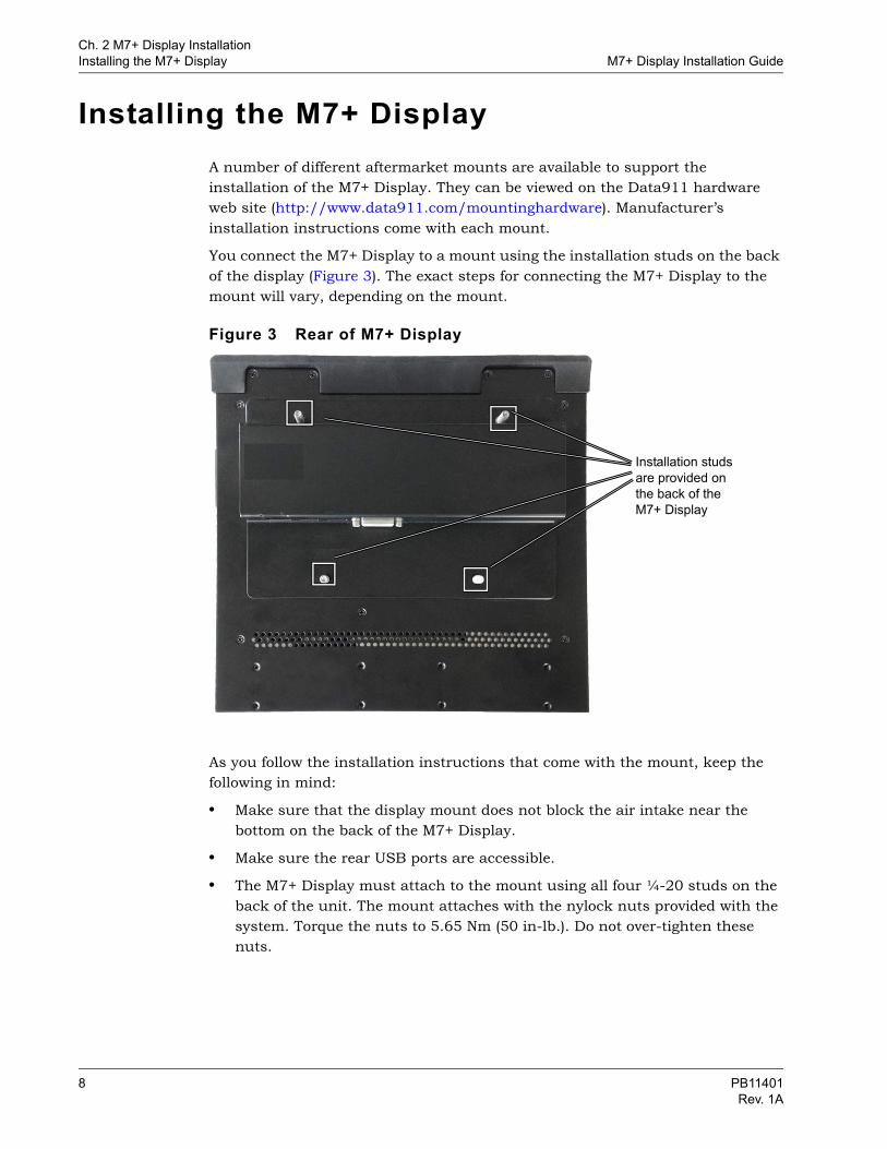
Connecting the Display to the KeyboardPlug the keyboard into the left rear USB port for the M7+ Display, as shown in Figure 4.
Note: Although it is possible to plug the keyboard into either of the USB ports, only the left rear USB connector can be controlled as part of the M7+ configuration. Configuration settings can include disabling the keyboard upon entering stealth mode, or on motion detection, if the keyboard is plugged into the left rear USB connector. For more information, see Changing Display Settings, on page 17.
Note: A USB extension cable can be ordered from Data911, should you need one.
Figure 4 M7+ Display and Keyboard Connected Via USB
USB Connection to keyboard. Use the left rear USB port.
PB11401 9Rev. 1A
Ch. 2 M7+ Display InstallationInstalling the M7+ Display M7+ Display Installation Guide
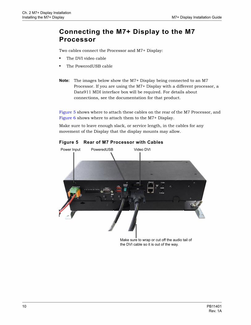
Connecting the M7+ Display to the M7 Processor Two cables connect the Processor and M7+ Display:
• The DVI video cable
• The PoweredUSB cable
Note: The images below show the M7+ Display being connected to an M7 Processor. If you are using the M7+ Display with a different processor, a Data911 MDI interface box will be required. For details about connections, see the documentation for that product.
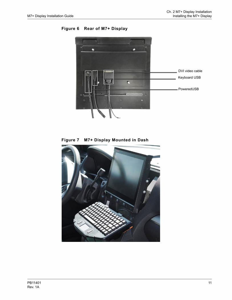
Figure 5 shows where to attach these cables on the rear of the M7 Processor, and Figure 6 shows where to attach them to the M7+ Display.
Make sure to leave enough slack, or service length, in the cables for any movement of the Display that the display mounts may allow.
Figure 5 Rear of M7 Processor with CablesVideo DVIPoweredUSB Power Input
Make sure to wrap or cut off the audio tail of the DVI cable so it is out of the way.
10 PB11401Rev. 1A
Ch. 2 M7+ Display InstallationM7+ Display Installation Guide Installing the M7+ Display
Figure 6 Rear of M7+ Display
Figure 7 M7+ Display Mounted in Dash
DVI video cable
Keyboard USB
PoweredUSB
PB11401 11Rev. 1A
Ch. 2 M7+ Display InstallationReplacing an M7 Display with an M7+ Display M7+ Display Installation Guide
Replacing an M7 Display with an M7+ Display
If you are replacing an M7 12” or 15” Display with an M7+ Display, keep these differences in mind.
• The M7+ is slightly larger
• There is no audio jack on the M7+ Display; audio is carried over USB.
• The keyboard must now be plugged into the left rear USB port of the display, when viewed from the back.
To replace an existing display with a 12” M7+ Display1. Detach the cables from the existing display.
2. Unscrew the nylock nuts for the current display, and remove that display
3. Attach the M7+ Display to the mount using all four ¼-20 studs on the back of the unit. Torque the nuts to 5.65 Nm (50 in-lb.). Do not over-tighten these nuts.
4. Connect the M7+ Display to the keyboard (see page 9).
5. Connect the cables you disconnected in step 1 to the M7+ Display.
12 PB11401Rev. 1A
Configuring the M7+ Display
C H A P T E R 3
This chapter explains how to configure the M7+ Display’s physical knobs and buttons through the MDC Manager application. It is organized into the following sections:Launching MDC Manager, on page 14
Setting and Changing the MDC Manager Password, on page 15
Configuring the M7+ Display Settings and Controls, on page 16– Changing Display Settings, on page 17– Setting Actions for Display Buttons and Knob Press: Basic Steps, on page 19
– Defining What Application to Launch, on page 21– Entering a Keystroke Sequence, on page 23– Examples of Keystroke Sequences, on page 25– Defining an Application Cycle, on page 26– Defining a Keystroke or Keystroke Sequence, on page 27
– Setting the Knob Turning Controls, on page 27– Changing the Background LED Color, on page 28
Working with Multiple Displays, on page 29
Reflashing the M7+ Display Firmware, on page 31
PB11401 13Rev. 1A
Ch. 3 Configuring the M7+ DisplayLaunching MDC Manager M7+ Display Installation Guide
Launching MDC ManagerThe MDC Manager is a software application that is used to view and configure Data911 product settings, such as the M7+ display settings. It has a User mode and an Admin mode.
The MDC Manager sits in the system tray, from which you can launch it. (If MDC Manager is not installed on your system, contact Data911 support. See page 3.)
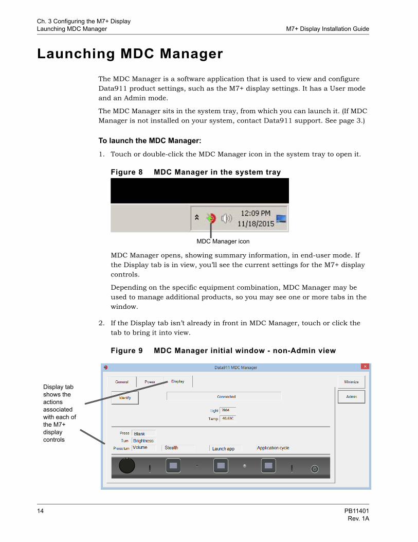
To launch the MDC Manager:1. Touch or double-click the MDC Manager icon in the system tray to open it.
Figure 8 MDC Manager in the system tray
MDC Manager opens, showing summary information, in end-user mode. If the Display tab is in view, you’ll see the current settings for the M7+ display controls.
Depending on the specific equipment combination, MDC Manager may be used to manage additional products, so you may see one or more tabs in the window.
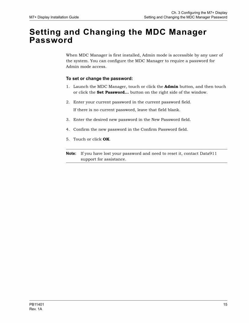
2. If the Display tab isn’t already in front in MDC Manager, touch or click the tab to bring it into view.
Figure 9 MDC Manager initial window - non-Admin view
MDC Manager icon
Display tab shows the actions associated with each of the M7+ display controls
14 PB11401Rev. 1A
Ch. 3 Configuring the M7+ DisplayM7+ Display Installation Guide Setting and Changing the MDC Manager Password
Setting and Changing the MDC Manager Password
When MDC Manager is first installed, Admin mode is accessible by any user of the system. You can configure the MDC Manager to require a password for Admin mode access.
To set or change the password:1. Launch the MDC Manager, touch or click the Admin button, and then touch
or click the Set Password... button on the right side of the window.
2. Enter your current password in the current password field.
If there is no current password, leave that field blank.
3. Enter the desired new password in the New Password field.
4. Confirm the new password in the Confirm Password field.
5. Touch or click OK.
Note: If you have lost your password and need to reset it, contact Data911 support for assistance.
PB11401 15Rev. 1A
Ch. 3 Configuring the M7+ DisplayConfiguring the M7+ Display Settings and Controls M7+ Display Installation Guide
Configuring the M7+ Display Settings and Controls
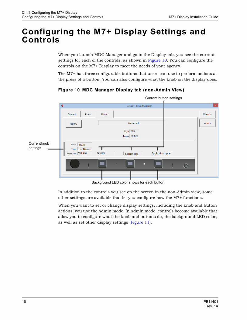
When you launch MDC Manager and go to the Display tab, you see the current settings for each of the controls, as shown in Figure 10. You can configure the controls on the M7+ Display to meet the needs of your agency.
The M7+ has three configurable buttons that users can use to perform actions at the press of a button. You can also configure what the knob on the display does.
Figure 10 MDC Manager Display tab (non-Admin View)
In addition to the controls you see on the screen in the non-Admin view, some other settings are available that let you configure how the M7+ functions.
When you want to set or change display settings, including the knob and button actions, you use the Admin mode. In Admin mode, controls become available that allow you to configure what the knob and buttons do, the background LED color, as well as set other display settings (Figure 11).
Current button settings
Current knob settings
Background LED color shows for each button
16 PB11401Rev. 1A
Ch. 3 Configuring the M7+ DisplayM7+ Display Installation Guide Configuring the M7+ Display Settings and Controls
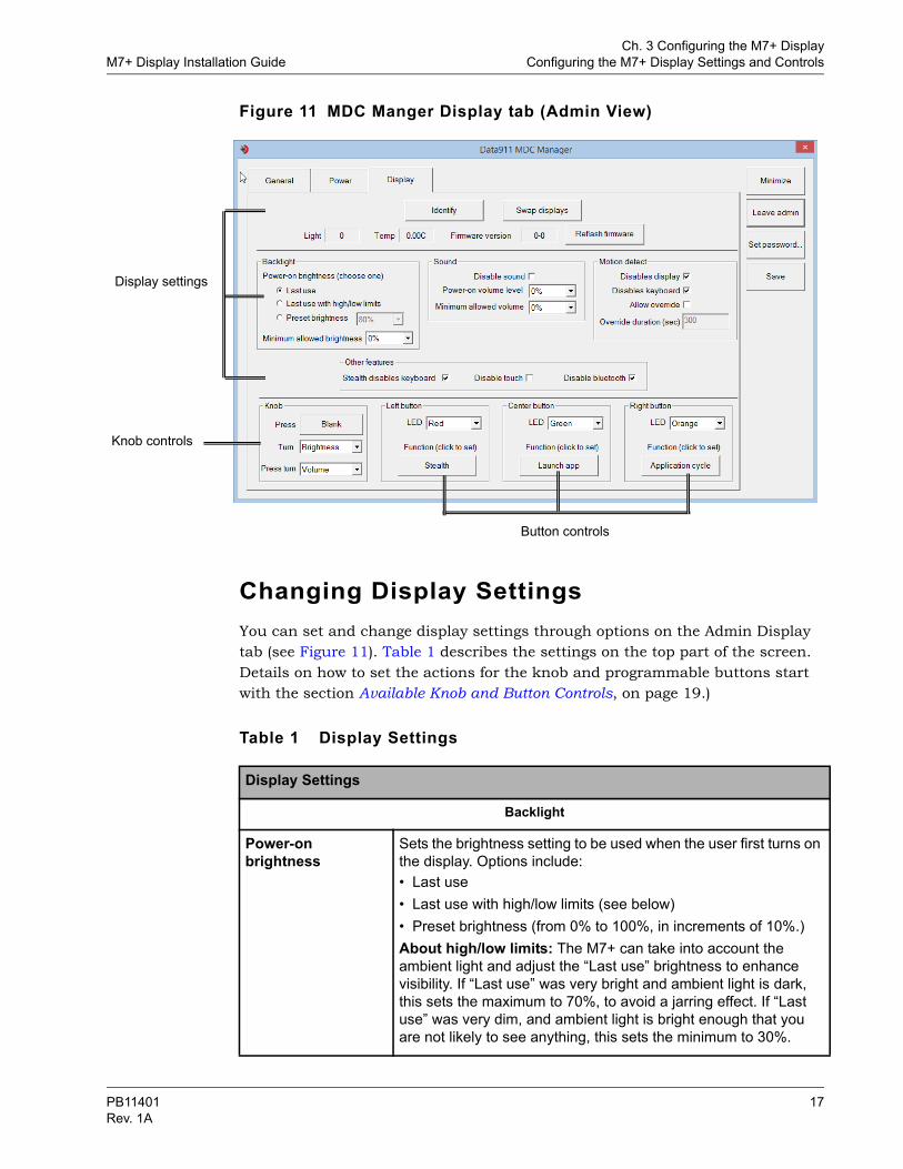
Figure 11 MDC Manger Display tab (Admin View)
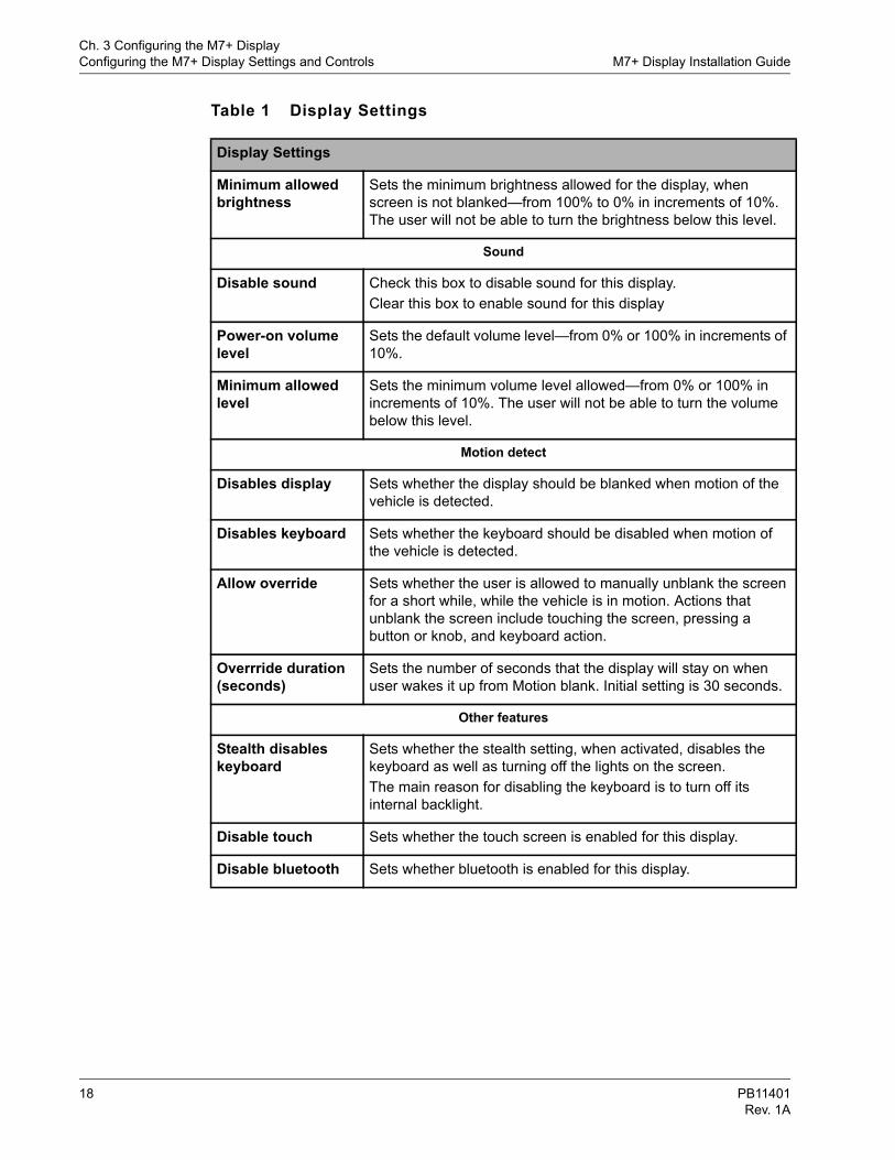
Changing Display SettingsYou can set and change display settings through options on the Admin Display tab (see Figure 11). Table 1 describes the settings on the top part of the screen. Details on how to set the actions for the knob and programmable buttons start with the section Available Knob and Button Controls, on page 19.)
Display settings
Knob controls
Button controls
Table 1 Display Settings
Display Settings
Backlight
Power-on brightness
Sets the brightness setting to be used when the user first turns on the display. Options include:• Last use• Last use with high/low limits (see below) • Preset brightness (from 0% to 100%, in increments of 10%.)About high/low limits: The M7+ can take into account the ambient light and adjust the “Last use” brightness to enhance visibility. If “Last use” was very bright and ambient light is dark, this sets the maximum to 70%, to avoid a jarring effect. If “Last use” was very dim, and ambient light is bright enough that you are not likely to see anything, this sets the minimum to 30%.
PB11401 17Rev. 1A
Ch. 3 Configuring the M7+ DisplayConfiguring the M7+ Display Settings and Controls M7+ Display Installation Guide
Minimum allowed brightness
Sets the minimum brightness allowed for the display, when screen is not blanked—from 100% to 0% in increments of 10%. The user will not be able to turn the brightness below this level.
Sound
Disable sound Check this box to disable sound for this display.Clear this box to enable sound for this display
Power-on volume level
Sets the default volume level—from 0% or 100% in increments of 10%.
Minimum allowed level
Sets the minimum volume level allowed—from 0% or 100% in increments of 10%. The user will not be able to turn the volume below this level.
Motion detect
Disables display Sets whether the display should be blanked when motion of the vehicle is detected.
Disables keyboard Sets whether the keyboard should be disabled when motion of the vehicle is detected.
Allow override Sets whether the user is allowed to manually unblank the screen for a short while, while the vehicle is in motion. Actions that unblank the screen include touching the screen, pressing a button or knob, and keyboard action.
Overrride duration (seconds)
Sets the number of seconds that the display will stay on when user wakes it up from Motion blank. Initial setting is 30 seconds.
Other features
Stealth disables keyboard
Sets whether the stealth setting, when activated, disables the keyboard as well as turning off the lights on the screen. The main reason for disabling the keyboard is to turn off its internal backlight.
Disable touch Sets whether the touch screen is enabled for this display.
Disable bluetooth Sets whether bluetooth is enabled for this display.
Table 1 Display Settings
Display Settings
18 PB11401Rev. 1A
Ch. 3 Configuring the M7+ DisplayM7+ Display Installation Guide Configuring the M7+ Display Settings and Controls
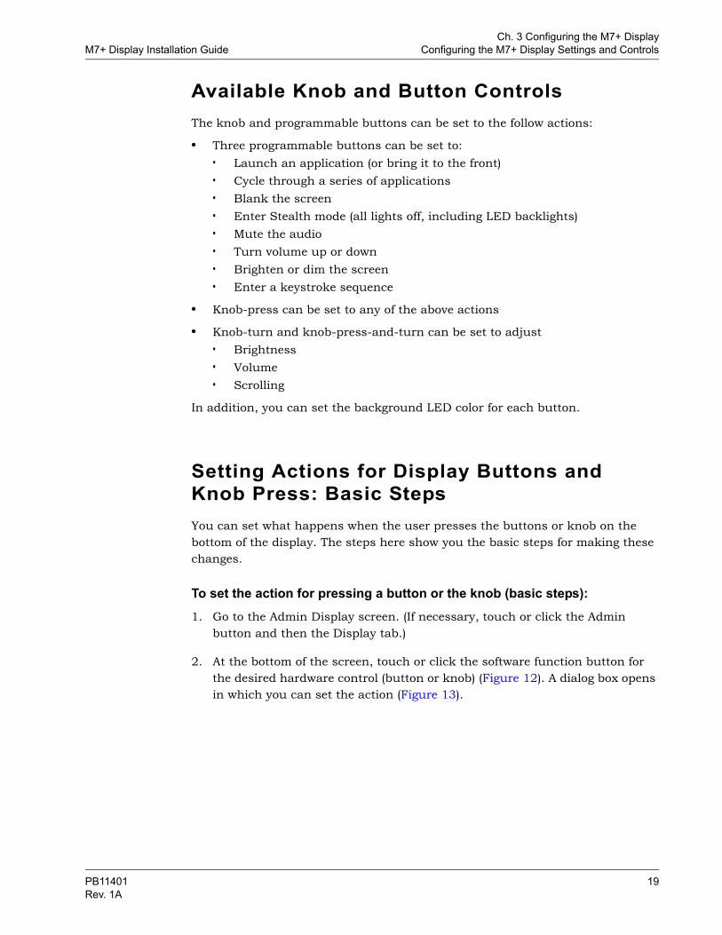
Available Knob and Button Controls The knob and programmable buttons can be set to the follow actions:
• Three programmable buttons can be set to:
Launch an application (or bring it to the front)
Cycle through a series of applications
Blank the screen
Enter Stealth mode (all lights off, including LED backlights)
Mute the audio
Turn volume up or down
Brighten or dim the screen
Enter a keystroke sequence
• Knob-press can be set to any of the above actions
• Knob-turn and knob-press-and-turn can be set to adjust
Brightness
Volume
Scrolling
In addition, you can set the background LED color for each button.
Setting Actions for Display Buttons and Knob Press: Basic StepsYou can set what happens when the user presses the buttons or knob on the bottom of the display. The steps here show you the basic steps for making these changes.
To set the action for pressing a button or the knob (basic steps):1. Go to the Admin Display screen. (If necessary, touch or click the Admin
button and then the Display tab.)
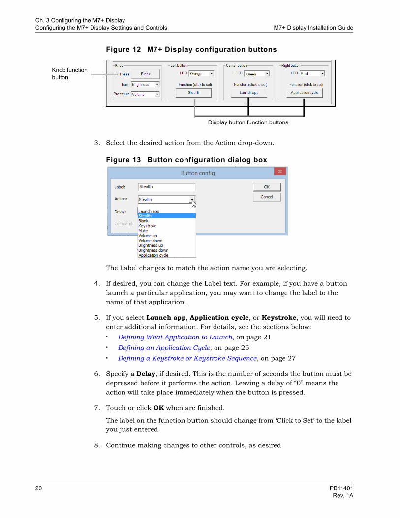
2. At the bottom of the screen, touch or click the software function button for the desired hardware control (button or knob) (Figure 12). A dialog box opens in which you can set the action (Figure 13).
PB11401 19Rev. 1A
Ch. 3 Configuring the M7+ DisplayConfiguring the M7+ Display Settings and Controls M7+ Display Installation Guide
Figure 12 M7+ Display configuration buttons
3. Select the desired action from the Action drop-down.
Figure 13 Button configuration dialog box
The Label changes to match the action name you are selecting.
4. If desired, you can change the Label text. For example, if you have a button launch a particular application, you may want to change the label to the name of that application.
5. If you select Launch app, Application cycle, or Keystroke, you will need to enter additional information. For details, see the sections below:
Defining What Application to Launch, on page 21
Defining an Application Cycle, on page 26
Defining a Keystroke or Keystroke Sequence, on page 27
6. Specify a Delay, if desired. This is the number of seconds the button must be depressed before it performs the action. Leaving a delay of “0” means the action will take place immediately when the button is pressed.
7. Touch or click OK when are finished.
The label on the function button should change from ‘Click to Set’ to the label you just entered.
8. Continue making changes to other controls, as desired.
Knob function button
Display button function buttons
20 PB11401Rev. 1A
Ch. 3 Configuring the M7+ DisplayM7+ Display Installation Guide Configuring the M7+ Display Settings and Controls
9. When you are finished, touch or click Save on the right-hand side of the MDC Manager screen.
10. If you are finished setting Display controls, touch or click Leave Admin.
Defining What Application to LaunchLaunching an application either starts an application or brings an application window to the front, if it is already running. If you are bringing an application to the front, you can also specify a keystroke sequence to be entered in the application. For example, if an officer wants to launch their dispatch software and change their status to “enroute,” you can configure one of the display buttons to do that for them.
To define an application to launch1. On the Admin Display screen, at the bottom of the screen, touch or click the
software function button for the desired hardware control (button or knob) (Figure 12).
2. In the Button Configuration dialog box that opens, select Launch App from the Action drop-down (Figure 13).
3. At the bottom of the Button Configuration dialog box, touch or click Configure.
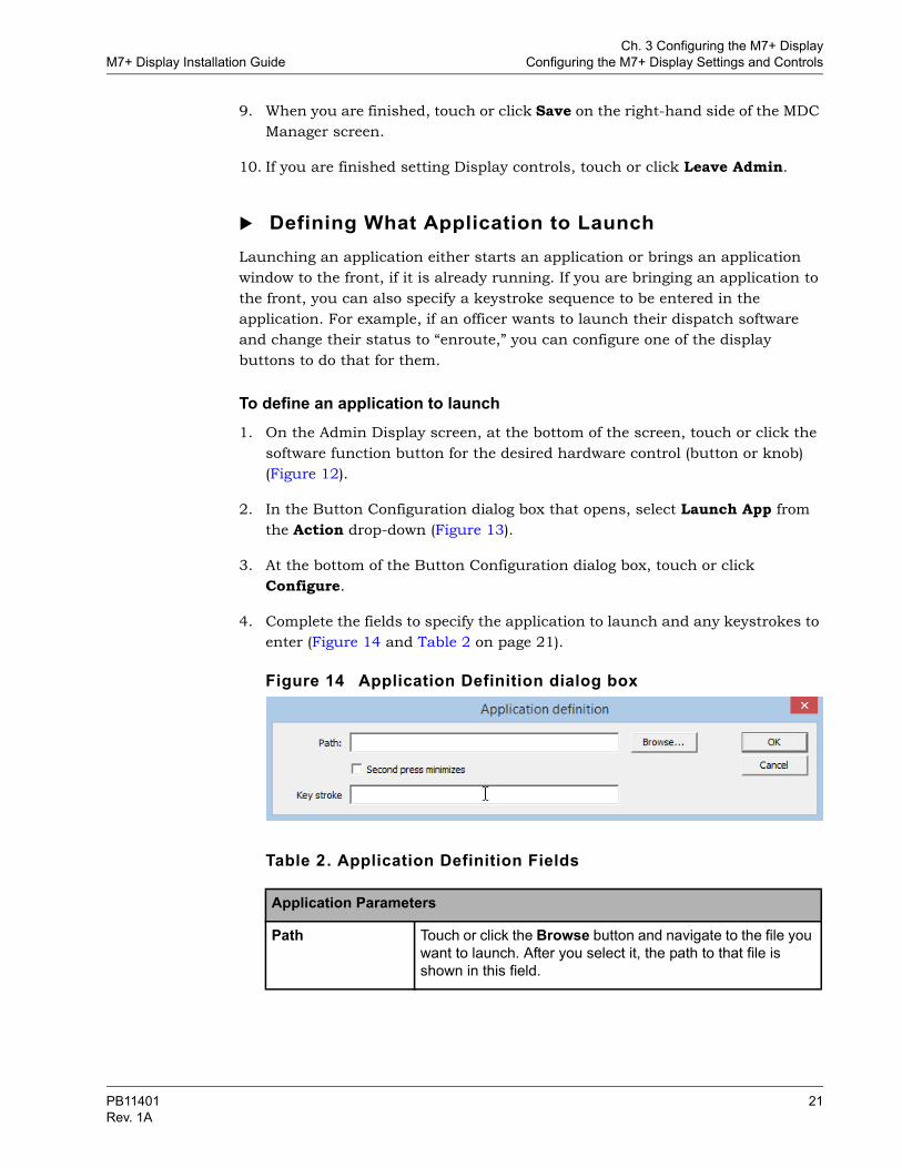
4. Complete the fields to specify the application to launch and any keystrokes to enter (Figure 14 and Table 2 on page 21).
Figure 14 Application Definition dialog box
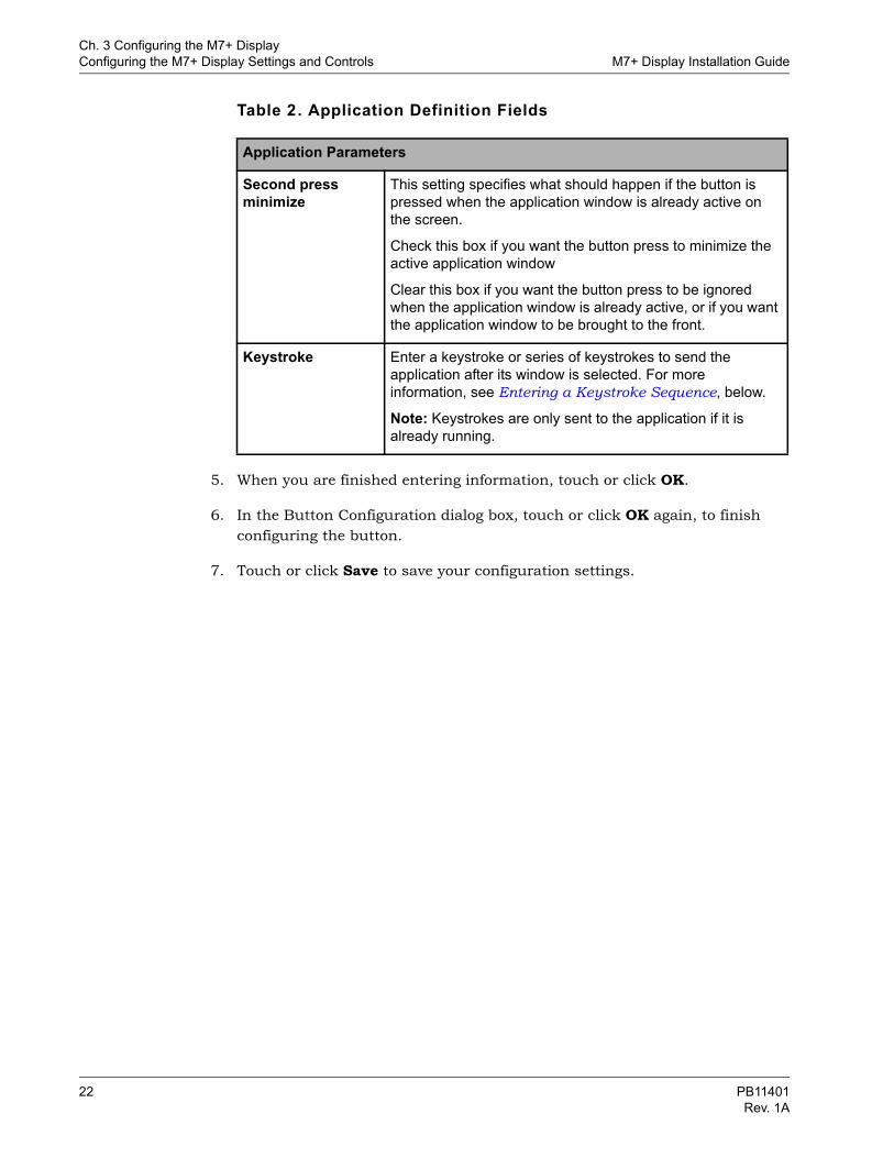
Table 2. Application Definition Fields
Application Parameters
Path Touch or click the Browse button and navigate to the file you want to launch. After you select it, the path to that file is shown in this field.
PB11401 21Rev. 1A
Ch. 3 Configuring the M7+ DisplayConfiguring the M7+ Display Settings and Controls M7+ Display Installation Guide
5. When you are finished entering information, touch or click OK.
6. In the Button Configuration dialog box, touch or click OK again, to finish configuring the button.
7. Touch or click Save to save your configuration settings.
Second press minimize
This setting specifies what should happen if the button is pressed when the application window is already active on the screen.
Check this box if you want the button press to minimize the active application window
Clear this box if you want the button press to be ignored when the application window is already active, or if you want the application window to be brought to the front.
Keystroke Enter a keystroke or series of keystrokes to send the application after its window is selected. For more information, see Entering a Keystroke Sequence, below.
Note: Keystrokes are only sent to the application if it is already running.
Table 2. Application Definition Fields
Application Parameters
22 PB11401Rev. 1A
Ch. 3 Configuring the M7+ DisplayM7+ Display Installation Guide Configuring the M7+ Display Settings and Controls
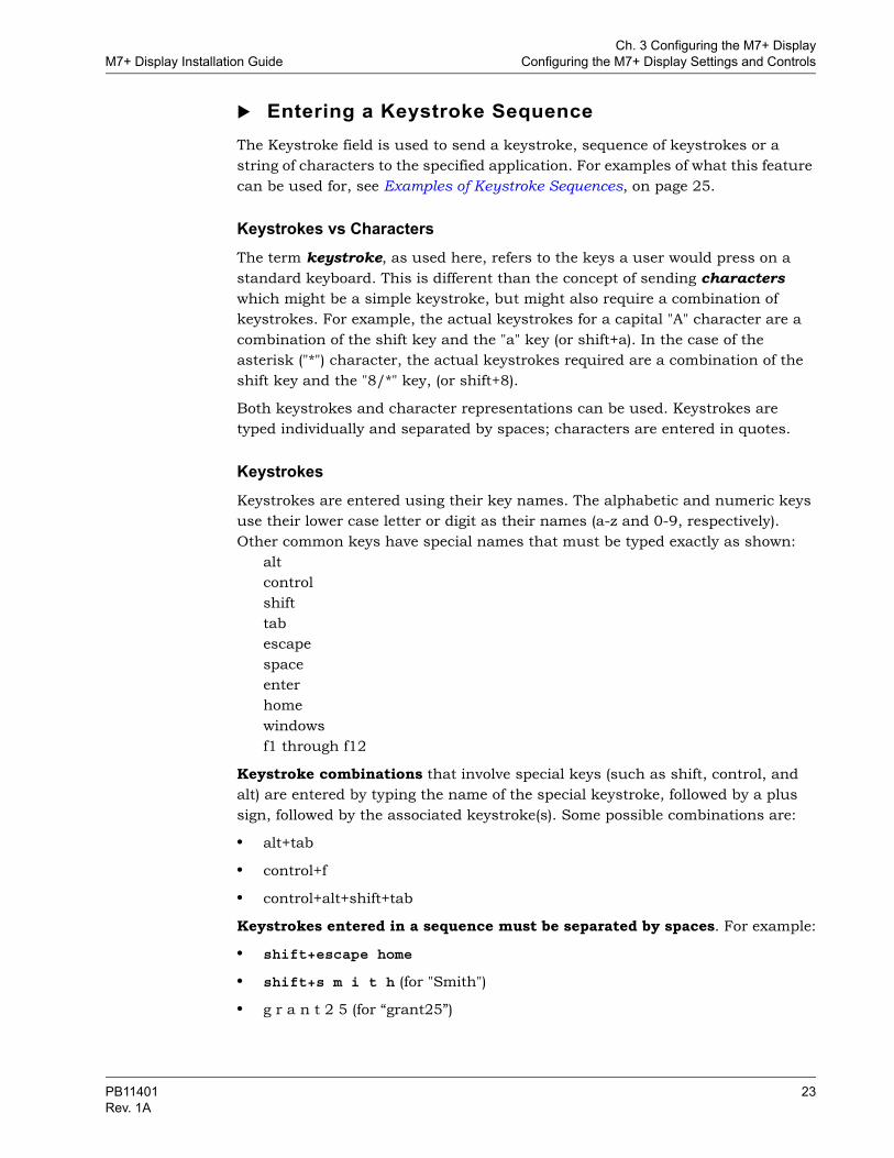
Entering a Keystroke SequenceThe Keystroke field is used to send a keystroke, sequence of keystrokes or a string of characters to the specified application. For examples of what this feature can be used for, see Examples of Keystroke Sequences, on page 25.
Keystrokes vs CharactersThe term keystroke, as used here, refers to the keys a user would press on a standard keyboard. This is different than the concept of sending characters which might be a simple keystroke, but might also require a combination of keystrokes. For example, the actual keystrokes for a capital "A" character are a combination of the shift key and the "a" key (or shift+a). In the case of the asterisk ("*") character, the actual keystrokes required are a combination of the shift key and the "8/*" key, (or shift+8).
Both keystrokes and character representations can be used. Keystrokes are typed individually and separated by spaces; characters are entered in quotes.
KeystrokesKeystrokes are entered using their key names. The alphabetic and numeric keys use their lower case letter or digit as their names (a-z and 0-9, respectively). Other common keys have special names that must be typed exactly as shown:
altcontrolshifttabescapespaceenterhomewindowsf1 through f12
Keystroke combinations that involve special keys (such as shift, control, and alt) are entered by typing the name of the special keystroke, followed by a plus sign, followed by the associated keystroke(s). Some possible combinations are:
• alt+tab
• control+f
• control+alt+shift+tab
Keystrokes entered in a sequence must be separated by spaces. For example:
• shift+escape home
• shift+s m i t h (for "Smith")
• g r a n t 2 5 (for “grant25”)
PB11401 23Rev. 1A
Ch. 3 Configuring the M7+ DisplayConfiguring the M7+ Display Settings and Controls M7+ Display Installation Guide
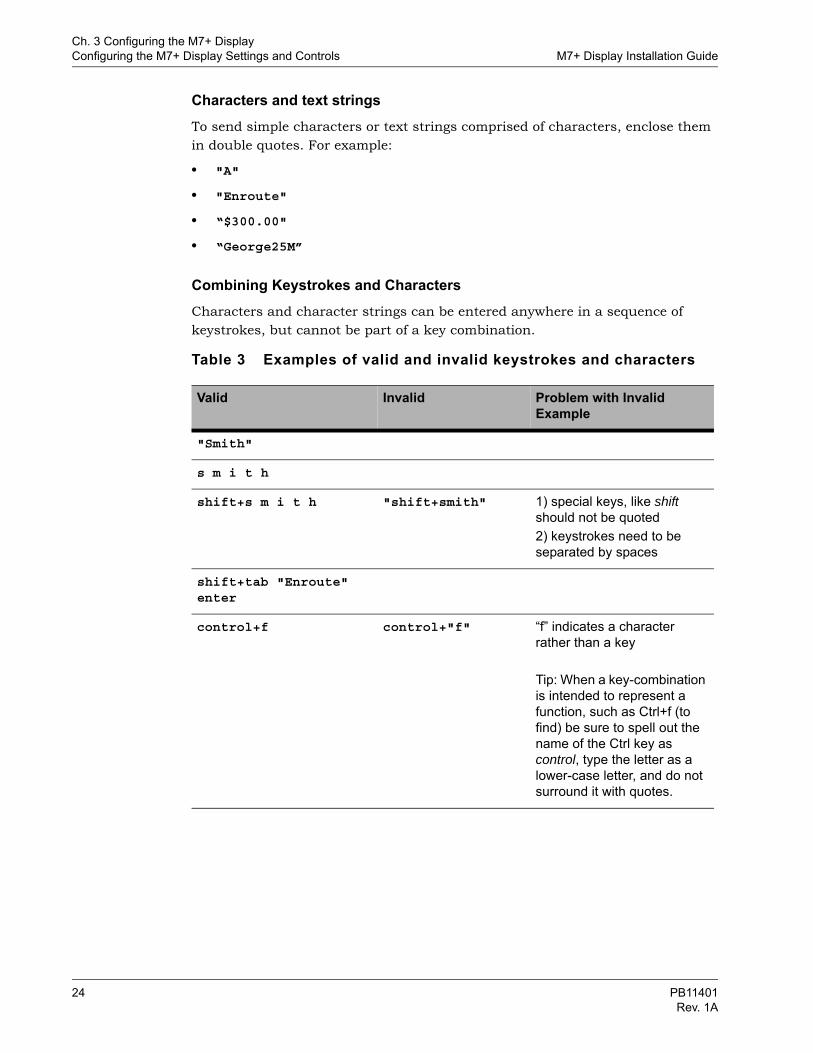
Characters and text stringsTo send simple characters or text strings comprised of characters, enclose them in double quotes. For example:
• "A"
• "Enroute"
• “$300.00"
• “George25M”
Combining Keystrokes and CharactersCharacters and character strings can be entered anywhere in a sequence of keystrokes, but cannot be part of a key combination.
Table 3 Examples of valid and invalid keystrokes and characters
Valid Invalid Problem with Invalid Example
"Smith"
s m i t h
shift+s m i t h "shift+smith" 1) special keys, like shift should not be quoted2) keystrokes need to be separated by spaces
shift+tab "Enroute" enter
control+f control+"f" “f” indicates a character rather than a key
Tip: When a key-combination is intended to represent a function, such as Ctrl+f (to find) be sure to spell out the name of the Ctrl key as control, type the letter as a lower-case letter, and do not surround it with quotes.
24 PB11401Rev. 1A
Ch. 3 Configuring the M7+ DisplayM7+ Display Installation Guide Configuring the M7+ Display Settings and Controls
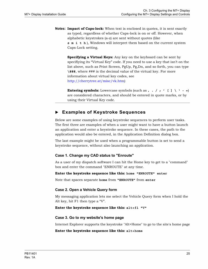
Notes: Impact of Caps-lock: When text is enclosed in quotes, it is sent exactly as typed, regardless of whether Caps-lock is on or off. However, when alphabetic keystrokes (a-z) are sent without quotes (like s m i t h ), Windows will interpret them based on the current system Caps-Lock setting.
Specifying a Virtual Keys: Any key on the keyboard can be sent by specifiying its “Virtual Key” code. If you need to use a key that isn’t on the list above, such as Print Screen, PgUp, Pg,Dn, and so forth, you can type \###, where ### is the decimal value of the virtual key. For more information about virtual key codes, see http://cherrytree.at/misc/vk.htm)
Entering symbols: Lowercase symbols (such as , . / ; ’ [ ] \ ‘ - =) are considered characters, and should be entered in quote marks, or by using their Virtual Key code.
Examples of Keystroke SequencesBelow are some examples of using keystroke sequences to perform user tasks. The first three are examples of when a user might want to have a button launch an application and enter a keystroke sequence. In these cases, the path to the application would also be entered, in the Application Definition dialog box.
The last example might be used when a programmable button is set to send a keystroke sequence, without also launching an application.
Case 1. Change my CAD status to "Enroute"As a user of my dispatch software I can hit the Home key to get to a "command" box and enter the command "ENROUTE" at any time.
Enter the keystroke sequence like this: home "ENROUTE" enter
Note that spaces separate home from “ENROUTE” from enter
Case 2. Open a Vehicle Query formMy messaging application lets me select the Vehicle Query form when I hold the Alt key, hit F1 then type a “V”.
Enter the keystroke sequence like this: alt+f1 "V"
Case 3. Go to my website's home pageInternet Explorer supports the keystroke "Alt+Home" to go to the site's home page
Enter the keystroke sequence like this: alt+home
PB11401 25Rev. 1A
Ch. 3 Configuring the M7+ DisplayConfiguring the M7+ Display Settings and Controls M7+ Display Installation Guide
Case 4. Show/hide the Windows desktopThe Windows keyboard shortcut to show/hide the Windows desktop is "Windows logo key +D"
Enter the keystroke sequence like this: windows+d
Note that the d is typed as a lowercase letter, and is not quoted.
Defining an Application CycleIf your end users regularly use a number of applications, you can set up one of the controls to cycle through those applications by repeatedly pressing the same button or knob.
1. On the Admin Display screen, at the bottom of the screen, touch or click the function button of the desired hardware control (button or knob) (Figure 12).
2. In the Button Configuration dialog box that opens, select Application Cycle from the Action drop-down (Figure 13).
3. At the bottom of the Button Configuration dialog box, touch or click Configure.
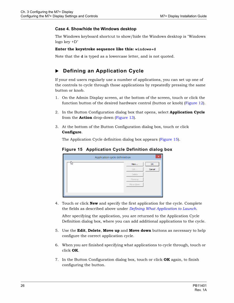
The Application Cycle definition dialog box appears (Figure 15).
Figure 15 Application Cycle Definition dialog box
4. Touch or click New and specify the first application for the cycle. Complete the fields as described above under Defining What Application to Launch.
After specifying the application, you are returned to the Application Cycle Definition dialog box, where you can add additional applications to the cycle.
5. Use the Edit, Delete, Move up and Move down buttons as necessary to help configure the correct application cycle.
6. When you are finished specifying what applications to cycle through, touch or click OK.
7. In the Button Configuration dialog box, touch or click OK again, to finish configuring the button.
26 PB11401Rev. 1A
Ch. 3 Configuring the M7+ DisplayM7+ Display Installation Guide Configuring the M7+ Display Settings and Controls
8. Touch or click Save to save your configuration settings.
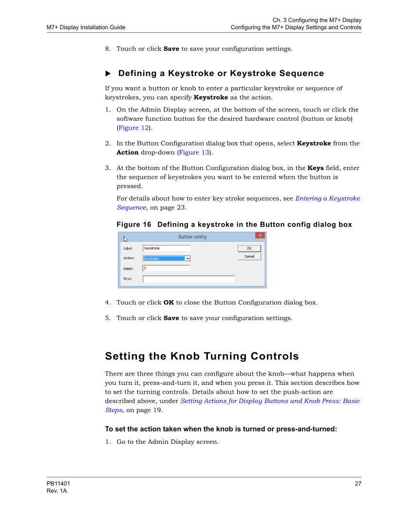
Defining a Keystroke or Keystroke SequenceIf you want a button or knob to enter a particular keystroke or sequence of keystrokes, you can specify Keystroke as the action.
1. On the Admin Display screen, at the bottom of the screen, touch or click the software function button for the desired hardware control (button or knob) (Figure 12).
2. In the Button Configuration dialog box that opens, select Keystroke from the Action drop-down (Figure 13).
3. At the bottom of the Button Configuration dialog box, in the Keys field, enter the sequence of keystrokes you want to be entered when the button is pressed.
For details about how to enter key stroke sequences, see Entering a Keystroke Sequence, on page 23.
Figure 16 Defining a keystroke in the Button config dialog box
4. Touch or click OK to close the Button Configuration dialog box.
5. Touch or click Save to save your configuration settings.
Setting the Knob Turning ControlsThere are three things you can configure about the knob—what happens when you turn it, press-and-turn it, and when you press it. This section describes how to set the turning controls. Details about how to set the push-action are described above, under Setting Actions for Display Buttons and Knob Press: Basic Steps, on page 19.
To set the action taken when the knob is turned or press-and-turned:1. Go to the Admin Display screen.
PB11401 27Rev. 1A
Ch. 3 Configuring the M7+ DisplayConfiguring the M7+ Display Settings and Controls M7+ Display Installation Guide
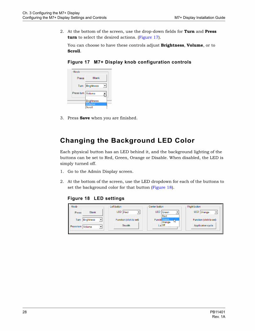
2. At the bottom of the screen, use the drop-down fields for Turn and Press turn to select the desired actions. (Figure 17).
You can choose to have these controls adjust Brightness, Volume, or to Scroll.
Figure 17 M7+ Display knob configuration controls
3. Press Save when you are finished.
Changing the Background LED ColorEach physical button has an LED behind it, and the background lighting of the buttons can be set to Red, Green, Orange or Disable. When disabled, the LED is simply turned off.
1. Go to the Admin Display screen.
2. At the bottom of the screen, use the LED dropdown for each of the buttons to set the background color for that button (Figure 18).
Figure 18 LED settings
28 PB11401Rev. 1A
Ch. 3 Configuring the M7+ DisplayM7+ Display Installation Guide Working with Multiple Displays
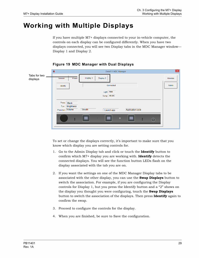
Working with Multiple DisplaysIf you have multiple M7+ displays connected to your in-vehicle computer, the controls on each display can be configured differently. When you have two displays connected, you will see two Display tabs in the MDC Manager window—Display 1 and Display 2.
Figure 19 MDC Manager with Dual Displays
To set or change the displays correctly, it’s important to make sure that you know which display you are setting controls for.
1. Go to the Admin Display tab and click or touch the Identify button to confirm which M7+ display you are working with. Identify detects the connected displays. You will see the function button LEDs flash on the display associated with the tab you are on.
2. If you want the settings on one of the MDC Manager Display tabs to be associated with the other display, you can use the Swap Displays button to switch the association. For example, if you are configuring the Display controls for Display 1, but you press the Identify button and a “2” shows on the display you thought you were configuring, touch the Swap Displays button to switch the association of the displays. Then press Identify again to confirm the swap.
3. Proceed to configure the controls for the display.
4. When you are finished, be sure to Save the configuration.
Tabs for two displays
PB11401 29Rev. 1A

Ch. 3 Configuring the M7+ DisplayWorking with Multiple Displays M7+ Display Installation Guide
Dual Display Touch ConfigurationIf the cursor on both displays is responding to the press on one touchscreen, you need to configure your Microsoft Windows tablet settings.
To configure the touch controls for dual displays1. Go to the Microsoft Windows control panel Tablet PC Settings.
Figure 20 Microsoft Windows control panels
2. In the Tablet PC dialog box, touch or click Setup.
Figure 21 Tablet PC dialog box
Touch or click Setup
30 PB11401Rev. 1A
Ch. 3 Configuring the M7+ DisplayM7+ Display Installation Guide Reflashing the M7+ Display Firmware
3. Follow the prompts on the screen to touch the designated display several times, press Enter, and then touch the other display.
When this process has been completed, touch should work correctly on both displays.
Reflashing the M7+ Display FirmwareNormally, new versions of the display firmware for your M7+ will be automatically updated when a new version of MDC Manager is installed.
While it is unlikely to be necessary, it is possible that during some trouble-shooting situations, Data911 Support may ask you to install an older version of the firmware. Should this occur, you can use the Reflash Firmware button to do so. Data911 Support will provide additional instructions in the event this is required.
PB11401 31Rev. 1A