Embed Size (px)
Citation preview
MA126-1R: That’s Solid! Multi-Body Part Modeling
Techniques with Autodesk Inventor®
Mark Flayler – IMAGINiT Technologies
MA327-1 Autodesk Inventor has the functionality to create multiple solids inside of the part
modeling environment. This technology enhances productivity by designing assemblies inside the context of a part file, enabling control of design tracking and modeling parameters in one location. Assemblies based on a robust part file can be created very quickly in this manner and you can also control updates to the assembly at the same time. This modeling approach reduces repetitive time in canvas on redundant tasks and aids the designer in creating geometry that matches up in size, shape, and continuity. This class is for any Autodesk Inventor user wanting to know more about how multi-body parts can increase modeling productivity and efficiency.
About the Speaker: Mark has been using Autodesk® products since 1999 in many different manufacturing environments. He has implemented Autodesk products for many diverse industries. Autodesk® Inventor® has profoundly augmented Mark's abilities, allowing him to bring 3D digital prototyping to the forefront of the industries with which he has interacted. Mark has extensive experience and a comprehensive understanding of the technical and practical business and human dimensions of implementation. His expertise has helped his clients maximize their project's effectiveness and return on investment. He is an effective and skillful communicator, consulting with his clients to help achieve their business objectives. Mark provides training, support, and implementation on all Autodesk manufacturing solutions.
Blog: http://blogs.rand.com/manufacturing/
That’s Solid! Multi-Body Part Modeling Techniques with Autodesk Inventor®
Introduction
Multi-Body modeling is one method of Top-Down design. Let’s take a look at a couple different modeling
practices in use in today’s Inventor community (Bottom-Up, Middle-Out, and Top-Down), and where Top-
Down design can help designers decrease rework and monotonous tasks.
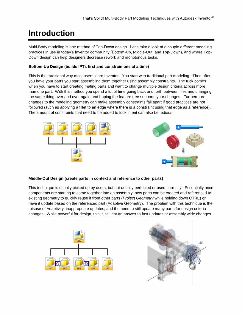
Bottom-Up Design (builds IPTs first and constrain one at a time)
This is the traditional way most users learn Inventor. You start with traditional part modeling. Then after
you have your parts you start assembling them together using assembly constraints. The trick comes
when you have to start creating mating parts and want to change multiple design criteria across more
than one part. With this method you spend a lot of time going back and forth between files and changing
the same thing over and over again and hoping the feature tree supports your changes. Furthermore,
changes to the modeling geometry can make assembly constraints fall apart if good practices are not
followed (such as applying a fillet to an edge where there is a constraint using that edge as a reference).
The amount of constraints that need to be added to lock intent can also be tedious.
Middle-Out Design (create parts in context and reference to other parts)
This technique is usually picked up by users, but not usually perfected or used correctly. Essentially once
components are starting to come together into an assembly, new parts can be created and referenced to
existing geometry to quickly reuse it from other parts (Project Geometry while holding down CTRL) or
have it update based on the referenced part (Adaptive Geometry). The problem with this technique is the
misuse of Adaptivity, inappropriate updates, and the need to still update many parts for design criteria
changes. While powerful for design, this is still not an answer to fast updates or assembly wide changes.
That’s Solid! Multi-Body Part Modeling Techniques with Autodesk Inventor®
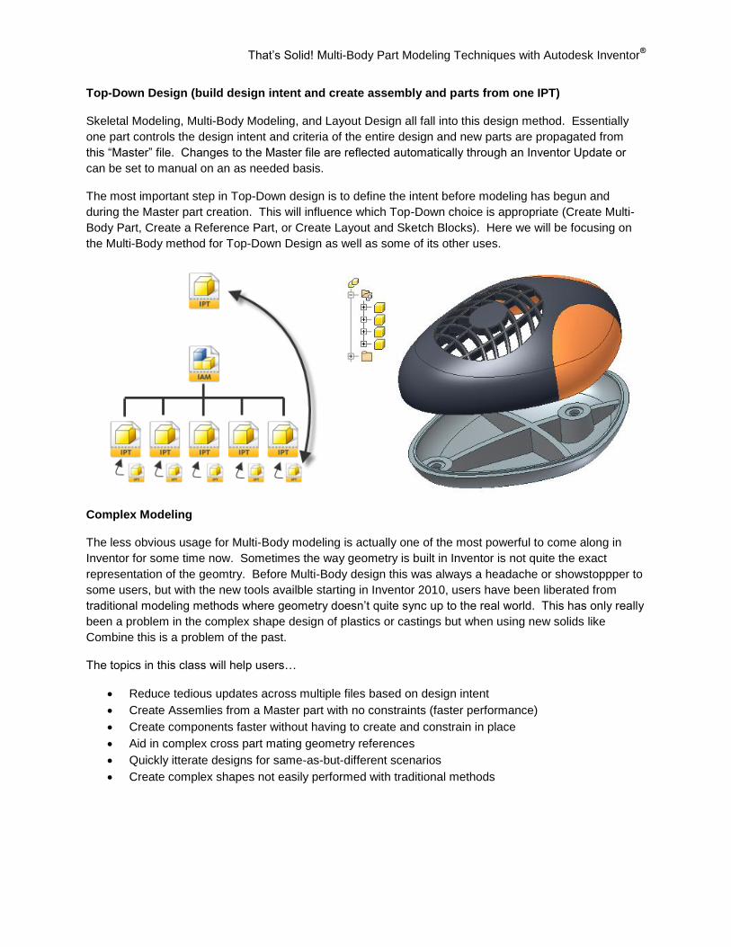
Top-Down Design (build design intent and create assembly and parts from one IPT)
Skeletal Modeling, Multi-Body Modeling, and Layout Design all fall into this design method. Essentially
one part controls the design intent and criteria of the entire design and new parts are propagated from
this “Master” file. Changes to the Master file are reflected automatically through an Inventor Update or
can be set to manual on an as needed basis.
The most important step in Top-Down design is to define the intent before modeling has begun and
during the Master part creation. This will influence which Top-Down choice is appropriate (Create Multi-
Body Part, Create a Reference Part, or Create Layout and Sketch Blocks). Here we will be focusing on
the Multi-Body method for Top-Down Design as well as some of its other uses.
Complex Modeling
The less obvious usage for Multi-Body modeling is actually one of the most powerful to come along in
Inventor for some time now. Sometimes the way geometry is built in Inventor is not quite the exact
representation of the geomtry. Before Multi-Body design this was always a headache or showstoppper to
some users, but with the new tools availble starting in Inventor 2010, users have been liberated from
traditional modeling methods where geometry doesn’t quite sync up to the real world. This has only really
been a problem in the complex shape design of plastics or castings but when using new solids like
Combine this is a problem of the past.
The topics in this class will help users…
Reduce tedious updates across multiple files based on design intent
Create Assemlies from a Master part with no constraints (faster performance)
Create components faster without having to create and constrain in place
Aid in complex cross part mating geometry references
Quickly itterate designs for same-as-but-different scenarios
Create complex shapes not easily performed with traditional methods
That’s Solid! Multi-Body Part Modeling Techniques with Autodesk Inventor®
Top-Down Backbone Technology
Inventor Multi-Body Modeling is the resultant of enhancements in derived parts and long developed user
workflows involving derived part models. Originally designed for Skeletal Modeling and Casting/Machining
tracking, derived parts allow one file to be linked to many others.
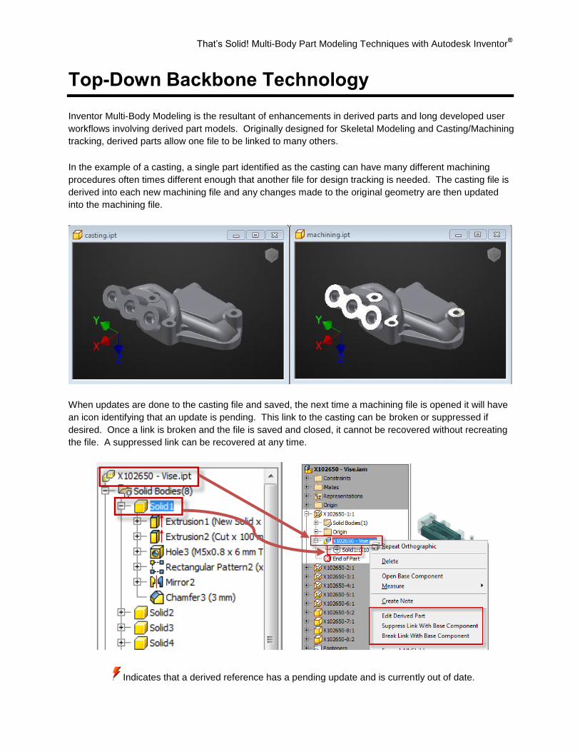
In the example of a casting, a single part identified as the casting can have many different machining
procedures often times different enough that another file for design tracking is needed. The casting file is
derived into each new machining file and any changes made to the original geometry are then updated
into the machining file.
When updates are done to the casting file and saved, the next time a machining file is opened it will have
an icon identifying that an update is pending. This link to the casting can be broken or suppressed if
desired. Once a link is broken and the file is saved and closed, it cannot be recovered without recreating
the file. A suppressed link can be recovered at any time.
Indicates that a derived reference has a pending update and is currently out of date.

That’s Solid! Multi-Body Part Modeling Techniques with Autodesk Inventor®
Parameters 2.0
Why 2.0? Because if you learned how to use parameters in the past but never fully appreciated them, you
will after this AU session. One of the most primitive concepts of parametric design is the proper use of
parameters. To utilize Multi-Body design to its fullest it will involve a fair amount of use of the parameters
table to not only control design criteria in a logical fashion, but also to allow easy modification of the design
criteria.
Parameters can be renamed and accessed without having to constantly open this dialog box. For instance
when you see this icon in an Edit Dimension box or Feature Dialog box, you can list a named
parameter to link to the modeling/sketch dimension.
A named parameter is any parameter that does not carry the default d* value where the * indicates a
unique identifier number. These are some rules for naming parameters…
Parameters cannot start with a number
Parameters are case sensitive (Length and length can both be used)
Parameters cannot have spaces (you can use underscore instead)
Parameters have reserved names that are used by Inventor and cannot be used (H, h, V, T, etc)
That’s Solid! Multi-Body Part Modeling Techniques with Autodesk Inventor®
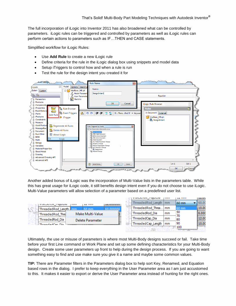
The full incorporation of iLogic into Inventor 2011 has also broadened what can be controlled by
parameters. iLogic rules can be triggered and controlled by parameters as well as iLogic rules can
perform certain actions to parameters such as IF…THEN and CASE statements.
Simplified workflow for iLogic Rules:
Use Add Rule to create a new iLogic rule
Define criteria for the rule in the iLogic dialog box using snippets and model data
Setup iTriggers to control how and when a rule is run
Test the rule for the design intent you created it for
Another added bonus of iLogic was the incorporation of Multi-Value lists in the parameters table. While
this has great usage for iLogic code, it still benefits design intent even if you do not choose to use iLogic.
Multi-Value parameters will allow selection of a parameter based on a predefined user list.
Ultimately, the use or misuse of parameters is where most Multi-Body designs succeed or fail. Take time
before your first Line command or Work Plane and set up some defining characteristics for your Multi-Body
design. Create some user parameters up front to help during the design process. If you are going to want
something easy to find and use make sure you give it a name and maybe some common values.
TIP: There are Parameter filters in the Parameters dialog box to help sort Key, Renamed, and Equation
based rows in the dialog. I prefer to keep everything in the User Parameter area as I am just accustomed
to this. It makes it easier to export or derive the User Parameter area instead of hunting for the right ones.
That’s Solid! Multi-Body Part Modeling Techniques with Autodesk Inventor®
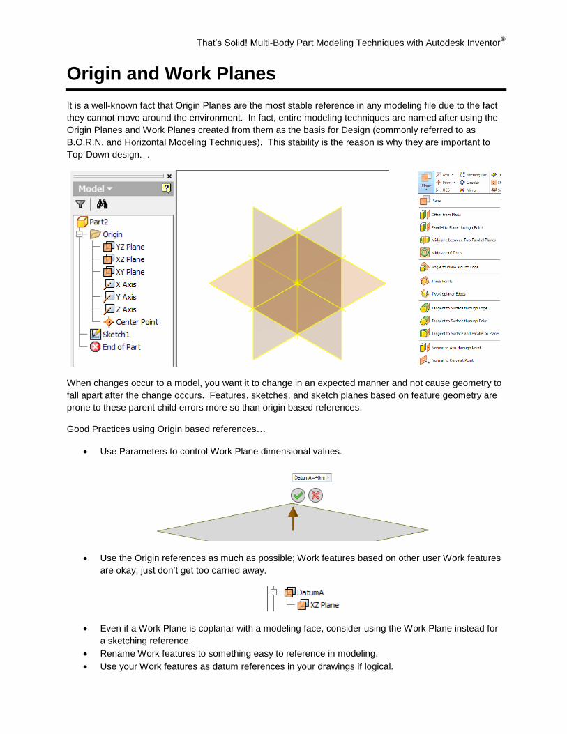
Origin and Work Planes
It is a well-known fact that Origin Planes are the most stable reference in any modeling file due to the fact
they cannot move around the environment. In fact, entire modeling techniques are named after using the
Origin Planes and Work Planes created from them as the basis for Design (commonly referred to as
B.O.R.N. and Horizontal Modeling Techniques). This stability is the reason is why they are important to
Top-Down design. .
When changes occur to a model, you want it to change in an expected manner and not cause geometry to
fall apart after the change occurs. Features, sketches, and sketch planes based on feature geometry are
prone to these parent child errors more so than origin based references.
Good Practices using Origin based references…
Use Parameters to control Work Plane dimensional values.
Use the Origin references as much as possible; Work features based on other user Work features
are okay; just don’t get too carried away.
Even if a Work Plane is coplanar with a modeling face, consider using the Work Plane instead for
a sketching reference.
Rename Work features to something easy to reference in modeling.
Use your Work features as datum references in your drawings if logical.
That’s Solid! Multi-Body Part Modeling Techniques with Autodesk Inventor®
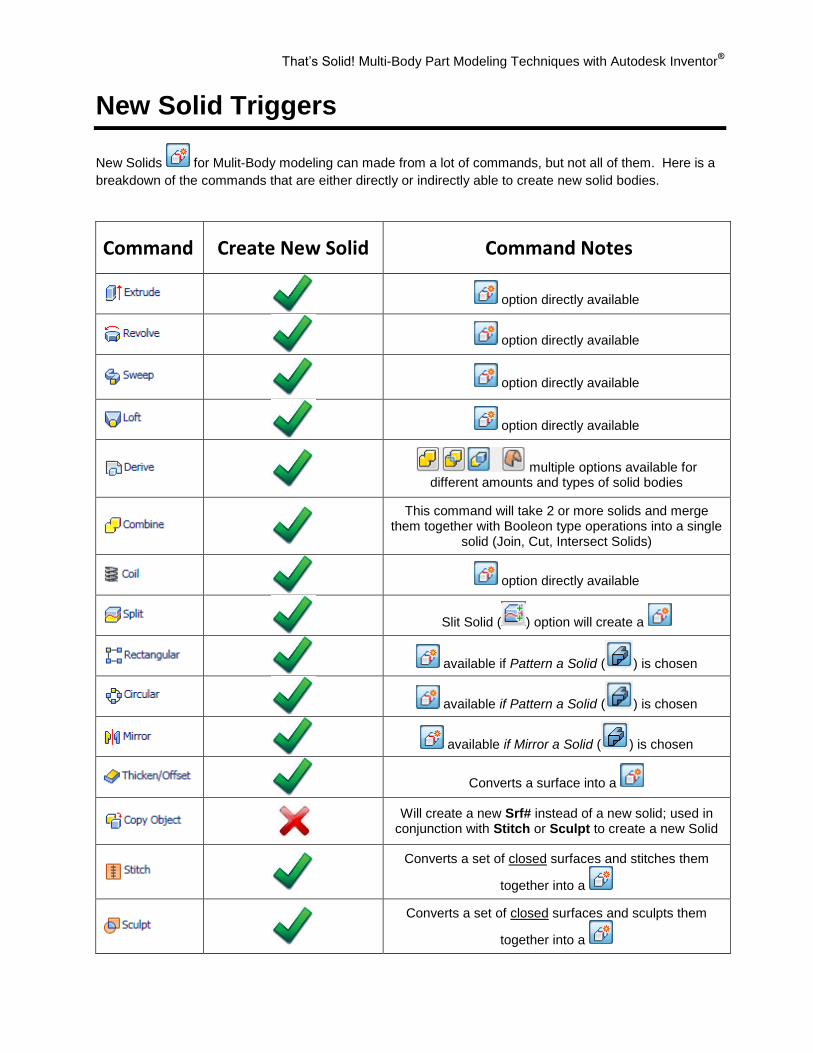
New Solid Triggers
New Solids
for Mulit-Body modeling can made from a lot of commands, but not all of them. Here is a
breakdown of the commands that are either directly or indirectly able to create new solid bodies.
Command Create New Solid Command Notes
option directly available
option directly available
option directly available
option directly available
multiple options available for different amounts and types of solid bodies
This command will take 2 or more solids and merge them together with Booleon type operations into a single
solid (Join, Cut, Intersect Solids)
option directly available
Slit Solid ( ) option will create a
available if Pattern a Solid ( ) is chosen
available if Pattern a Solid ( ) is chosen
available if Mirror a Solid ( ) is chosen
Converts a surface into a
Will create a new Srf# instead of a new solid; used in conjunction with Stitch or Sculpt to create a new Solid
Converts a set of closed surfaces and stitches them
together into a
Converts a set of closed surfaces and sculpts them
together into a
That’s Solid! Multi-Body Part Modeling Techniques with Autodesk Inventor®
Building the Multi-Body Part
After your design intent is hashed out, we can begin building a Multi-Body part. There really isn’t a rhyme
or reason to creating your initial solid except that you need to look forward in your design and see what
makes sense. You might start out with what you would consider a base part in an assembly or perhaps
an overall shape for a plastic part before splitting and shelling.
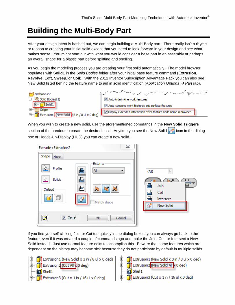
As you begin the modeling process you are creating your first solid automatically. The model browser
populates with Solid1 in the Solid Bodies folder after your initial base feature command (Extrusion,
Revolve, Loft, Sweep, or Coil). With the 2011 Inventor Subscription Advantage Pack you can also see
New Solid listed behind the feature name to aid in solid identification (Application Options Part tab).
When you wish to create a new solid, use the aforementioned commands in the New Solid Triggers
section of the handout to create the desired solid. Anytime you see the New Solid icon in the dialog
box or Heads-Up-Display (HUD) you can create a new solid.
If you find yourself clicking Join or Cut too quickly in the dialog boxes, you can always go back to the
feature even if it was created a couple of commands ago and make the Join, Cut, or Intersect a New
Solid instead. Just use normal feature edits to accomplish this. Beware that some features which are
dependent on the history may become sick because they do not participate by default in multiple solids.
That’s Solid! Multi-Body Part Modeling Techniques with Autodesk Inventor®
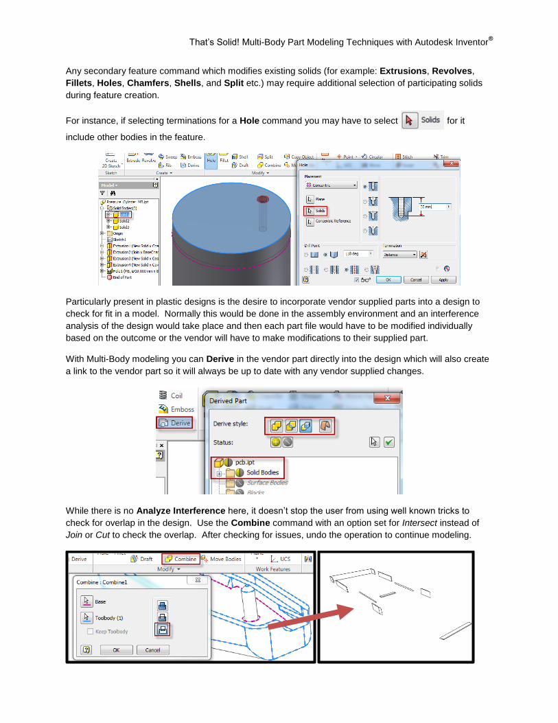
Any secondary feature command which modifies existing solids (for example: Extrusions, Revolves,
Fillets, Holes, Chamfers, Shells, and Split etc.) may require additional selection of participating solids
during feature creation.
For instance, if selecting terminations for a Hole command you may have to select for it
include other bodies in the feature.
Particularly present in plastic designs is the desire to incorporate vendor supplied parts into a design to
check for fit in a model. Normally this would be done in the assembly environment and an interference
analysis of the design would take place and then each part file would have to be modified individually
based on the outcome or the vendor will have to make modifications to their supplied part.
With Multi-Body modeling you can Derive in the vendor part directly into the design which will also create
a link to the vendor part so it will always be up to date with any vendor supplied changes.
While there is no Analyze Interference here, it doesn’t stop the user from using well known tricks to
check for overlap in the design. Use the Combine command with an option set for Intersect instead of
Join or Cut to check the overlap. After checking for issues, undo the operation to continue modeling.
Build the Foundation: Autodesk® Inventor
® Drawing Templates
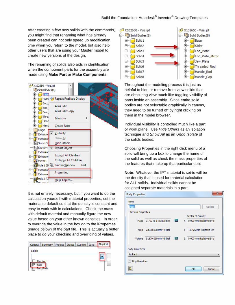
After creating a few new solids with the commands,
you might find that renaming what has already
been created can not only speed up modification
time when you return to the model, but also help
other users that are using your Master model to
create new versions of the design.
The renaming of solids also aids in identification
when the component parts for the assembly are
made using Make Part or Make Components.
Throughout the modeling process it is just as
helpful to hide or remove from view solids that
are obscuring view much like toggling visibility of
parts inside an assembly. Since entire solid
bodies are not selectable graphically in canvas,
they need to be turned off by right clicking on
them in the model browser.
Individual Visibility is controlled much like a part
or work plane. Use Hide Others as an isolation
technique and Show All as an Undo Isolate of
the solids bodies.
Choosing Properties in the right click menu of a
solid will bring up a box to change the name of
the solid as well as check the mass properties of
the features that make up that particular solid.
Note: Whatever the IPT material is set to will be
the density that is used for material calculation
for ALL solids. Individual solids cannot be
assigned separate materials in a part.
It is not entirely necessary, but if you want to do the
calculation yourself with material properties, set the
material to default so that the density is constant and
easy to work with in calculations. Check the mass
with default material and manually figure the new
value based on your other known densities. In order
to override the value in the box go to the iProperties
(image below) of the part file. This is actually a better
place to do your checking and overriding of values.
Build the Foundation: Autodesk® Inventor
® Drawing Templates
Creating your Assembly
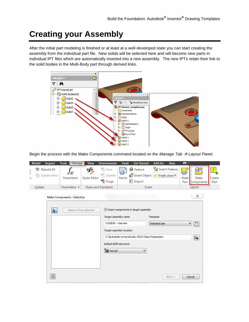
After the initial part modeling is finished or at least at a well-developed state you can start creating the
assembly from the individual part file. New solids will be selected here and will become new parts in
individual IPT files which are automatically inserted into a new assembly. The new IPTs retain their link to
the solid bodies in the Multi-Body part through derived links.
Begin the process with the Make Components command located on the Manage Tab Layout Panel.
That’s Solid! Multi-Body Part Modeling Techniques with Autodesk Inventor®
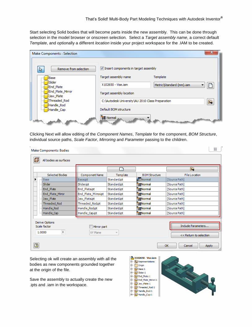
Start selecting Solid bodies that will become parts inside the new assembly. This can be done through
selection in the model browser or onscreen selection. Select a Target assembly name, a correct default
Template, and optionally a different location inside your project workspace for the .IAM to be created.
Clicking Next will allow editing of the Component Names, Template for the component, BOM Structure,
individual source paths, Scale Factor, Mirroring and Parameter passing to the children.
Selecting ok will create an assembly with all the
bodies as new components grounded together
at the origin of the file.
Save the assembly to actually create the new
.ipts and .iam in the workspace.
Build the Foundation: Autodesk® Inventor
® Drawing Templates
What to do after Make Components
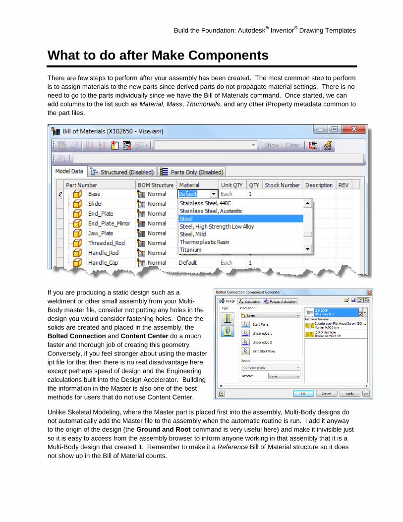
There are few steps to perform after your assembly has been created. The most common step to perform
is to assign materials to the new parts since derived parts do not propagate material settings. There is no
need to go to the parts individually since we have the Bill of Materials command. Once started, we can
add columns to the list such as Material, Mass, Thumbnails, and any other iProperty metadata common to
the part files.
If you are producing a static design such as a
weldment or other small assembly from your Multi-
Body master file, consider not putting any holes in the
design you would consider fastening holes. Once the
solids are created and placed in the assembly, the
Bolted Connection and Content Center do a much
faster and thorough job of creating this geometry.
Conversely, if you feel stronger about using the master
ipt file for that then there is no real disadvantage here
except perhaps speed of design and the Engineering
calculations built into the Design Accelerator. Building
the information in the Master is also one of the best
methods for users that do not use Content Center.
Unlike Skeletal Modeling, where the Master part is placed first into the assembly, Multi-Body designs do
not automatically add the Master file to the assembly when the automatic routine is run. I add it anyway
to the origin of the design (the Ground and Root command is very useful here) and make it inivisible just
so it is easy to access from the assembly browser to inform anyone working in that assembly that it is a
Multi-Body design that created it. Remember to make it a Reference Bill of Material structure so it does
not show up in the Bill of Material counts.
That’s Solid! Multi-Body Part Modeling Techniques with Autodesk Inventor®
Tolerances
Tolerance inspection is another benefit of Multi-Body
modeling or for that matter any Top-Down design
method.
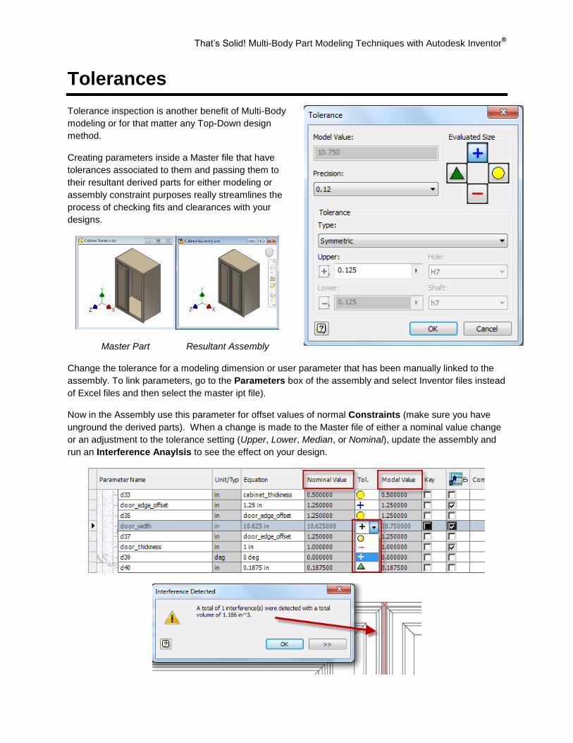
Creating parameters inside a Master file that have
tolerances associated to them and passing them to
their resultant derived parts for either modeling or
assembly constraint purposes really streamlines the
process of checking fits and clearances with your
designs.
Master Part Resultant Assembly
Change the tolerance for a modeling dimension or user parameter that has been manually linked to the
assembly. To link parameters, go to the Parameters box of the assembly and select Inventor files instead
of Excel files and then select the master ipt file).
Now in the Assembly use this parameter for offset values of normal Constraints (make sure you have
unground the derived parts). When a change is made to the Master file of either a nominal value change
or an adjustment to the tolerance setting (Upper, Lower, Median, or Nominal), update the assembly and
run an Interference Anaylsis to see the effect on your design.
That’s Solid! Multi-Body Part Modeling Techniques with Autodesk Inventor®
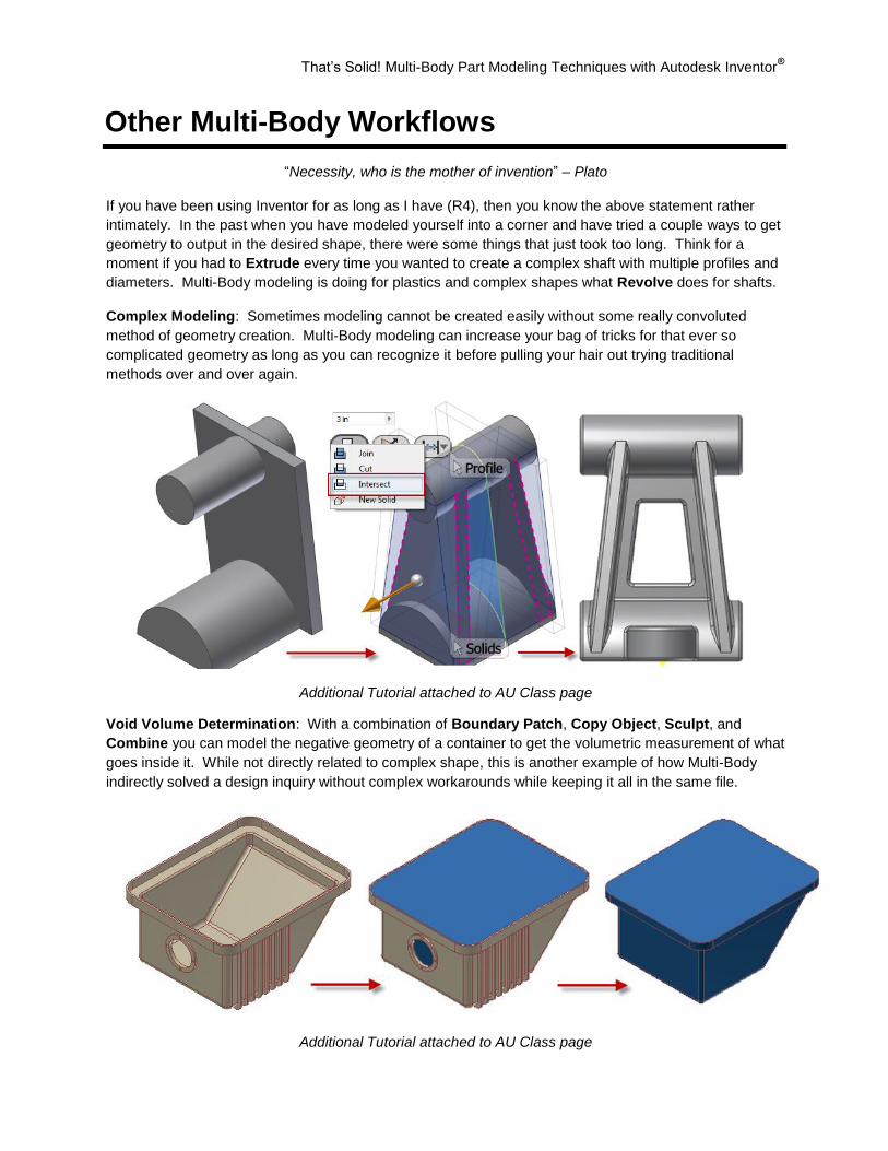
Other Multi-Body Workflows
“Necessity, who is the mother of invention” – Plato
If you have been using Inventor for as long as I have (R4), then you know the above statement rather
intimately. In the past when you have modeled yourself into a corner and have tried a couple ways to get
geometry to output in the desired shape, there were some things that just took too long. Think for a
moment if you had to Extrude every time you wanted to create a complex shaft with multiple profiles and
diameters. Multi-Body modeling is doing for plastics and complex shapes what Revolve does for shafts.
Complex Modeling: Sometimes modeling cannot be created easily without some really convoluted
method of geometry creation. Multi-Body modeling can increase your bag of tricks for that ever so
complicated geometry as long as you can recognize it before pulling your hair out trying traditional
methods over and over again.
Additional Tutorial attached to AU Class page
Void Volume Determination: With a combination of Boundary Patch, Copy Object, Sculpt, and
Combine you can model the negative geometry of a container to get the volumetric measurement of what
goes inside it. While not directly related to complex shape, this is another example of how Multi-Body
indirectly solved a design inquiry without complex workarounds while keeping it all in the same file.
Additional Tutorial attached to AU Class page
Build the Foundation: Autodesk® Inventor
® Drawing Templates
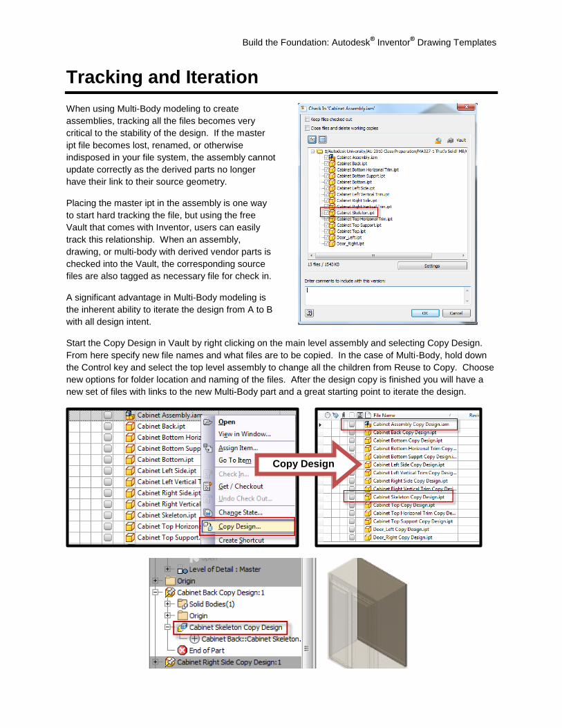
Tracking and Iteration
When using Multi-Body modeling to create
assemblies, tracking all the files becomes very
critical to the stability of the design. If the master
ipt file becomes lost, renamed, or otherwise
indisposed in your file system, the assembly cannot
update correctly as the derived parts no longer
have their link to their source geometry.
Placing the master ipt in the assembly is one way
to start hard tracking the file, but using the free
Vault that comes with Inventor, users can easily
track this relationship. When an assembly,
drawing, or multi-body with derived vendor parts is
checked into the Vault, the corresponding source
files are also tagged as necessary file for check in.
A significant advantage in Multi-Body modeling is
the inherent ability to iterate the design from A to B
with all design intent.
Start the Copy Design in Vault by right clicking on the main level assembly and selecting Copy Design.
From here specify new file names and what files are to be copied. In the case of Multi-Body, hold down
the Control key and select the top level assembly to change all the children from Reuse to Copy. Choose
new options for folder location and naming of the files. After the design copy is finished you will have a
new set of files with links to the new Multi-Body part and a great starting point to iterate the design.
Copy Design
That’s Solid! Multi-Body Part Modeling Techniques with Autodesk Inventor®
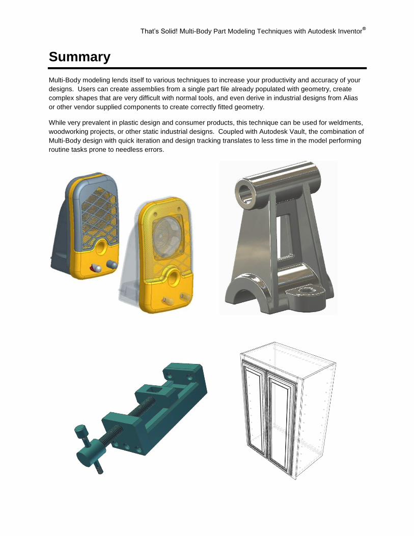
Summary
Multi-Body modeling lends itself to various techniques to increase your productivity and accuracy of your
designs. Users can create assemblies from a single part file already populated with geometry, create
complex shapes that are very difficult with normal tools, and even derive in industrial designs from Alias
or other vendor supplied components to create correctly fitted geometry.
While very prevalent in plastic design and consumer products, this technique can be used for weldments,
woodworking projects, or other static industrial designs. Coupled with Autodesk Vault, the combination of
Multi-Body design with quick iteration and design tracking translates to less time in the model performing
routine tasks prone to needless errors.

That’s Solid! Multi-Body Part Modeling Techniques with Autodesk Inventor®
Multi-Body FAQ
Q: I created two or more solid bodies in my part file and now when I create a drawing from that part file, I
cannot hide individual bodies from being shown. How do I do this?
A: You can do one of two things here:
1. Use Make Components or Make Part to create a new IPT and document that new part file.
2. Use Delete Face on the solid you do not want to see which will convert it from a solid to a surface
and then in the drawing turn off the surfaces for the part.
Q: Can I add a Multi-Body solid to the Content Center to create standard assemblies from it?
A: Yes, you can publish a Multi-Body part to the content center. When you decide to place it you will
have to create your assembly from that point though.
Q: How can I get materials to pass down from the Multi-Body r file to the children parts?
A: Short answer…you can’t. Long answer…it is possible with iLogic, but not practical to every user.
Instead create your assembly and use the BOM Editor to assign materials quickly over multiple parts.
Q: I don’t like the term “Solid”, how can I change this? Also I want to control the naming of the defaults in
the Make Components box
A: In your Part templates or existing Multi-Body part go to Tools Tab Document Settings. On the
Modeling tab of this dialog is controls for Solid and Surface naming as well as settings for the Make
Components dialog box.
Q: What if I add another solid to the Multi-Body part? Do I have to use Make Components again and
recreate my assembly?
A: No you can use Make Part to push your new solid into a new .ipt file and then simply use normal
grounding and origin tools such as Ground and Root Component or Place at Component Origin in the
assembly to place it.
That’s Solid! Multi-Body Part Modeling Techniques with Autodesk Inventor®
Appendix: Related Classes
Become the Master: New Multi-Body Modeling Technique in Inventor 2010
Class ID: MA318-5 AU: 2009 Speaker: Ralph Hartmann
Class Description: New features are always an interesting Issue for any CAD user. Inventor
2010 not only brings you the new feature of multi-body modeling, but there is a whole new way
of thinking behind this concept. It combines advanced top-down modeling (from assemblies)
with all the advantages of working within one Inventor Part. The strategy of building up the
perfect Inventor multi-body model and getting a robust parametric assembly out of your Part is
presented in this class. Attendees will learn when, how, and why to use this new modeling
technique. An interesting lecture for application engineers, technicians and a must-have for
anyone working with Inventor in the field of developing or designing products.
A View from the Top: Top-Down Design Techniques in Autodesk Inventor
Class ID: MA322-2L AU: 2010 Speaker: Mark Flayler
Class Description: Autodesk Inventor has the ability to perform multiple top-down design
techniques. Top-down approaches emphasize planning and a complete understanding of the
system. It is inherent that no modeling can begin until a sufficient level of detail has been
reached in the design of at least some part of the system. The modification of any top-down
design technique is inherently productive since it is focused on the modification of the few to
update and change the many. This method can drastically reduce time in canvas and repetitive
updates to numerous modeling files. This lab is for any users who want to understand how top-
down design can aid them in their design intent and efficiency.
The New Kid in Town: Autodesk Inventor in Consumer Products
Class ID: MA222-3 AU: 2009 Speaker: Jamie Gilchrist / Jay Tedeschi
Class Description: Autodesk Inventor has the ability to perform multiple top-down design
techniques. Top-down approaches emphasize planning and a complete understanding of the
system. It is inherent that no modeling can begin until a sufficient level of detail has been
reached in the design of at least some part of the system. The modification of any top-down
design technique is inherently productive since it is focused on the modification of the few to
update and change the many. This method can drastically reduce time in canvas and repetitive
updates to numerous modeling files. This lab is for any users who want to understand how top-
down design can aid them in their design intent and efficiency.