Embed Size (px)
Citation preview
MAC DN 40÷400 PVDF
Butterfly valve
1
MACVALVE MODEL
OCONNECTION STD.
CMATERIALS
VKD ball 2-way DUAL BLOCK® I ISO socket (metric) A ABS
TKD ball 3-way DUAL BLOCK® T D ISO spigot (metric) C PVC-C
LKD portball 3-way DUAL BLOCK® L B ISO butt welding (metric) F PVDF
VKR regulating ball 2-way DUAL BLOCK® BE PE100 ISO butt welding (metric) M PP-H
VXE ball 2-way Easyfit G JIS socket threaded (inch) V PVC-U
VEE ball 2-way Easyfit P Hose adaptor (metric) T PVC-U Transparent
SXE ball spring check valve Easyfit F BSP female threaded (inch)
MAC butterfly multi-purpose R BSP male threaded (inch)
FE butterfly water L BS female (inch)
VM diaphragm M BS male (inch)
VMU unionised diaphragm A ASTM socket (inch)
CM compact diaphragm Y ASTM spigot (inch)
CMU unionised compact diaphragm N NPT socket threaded (inch)
DM direct acting diaphragm (only pneumatically actuated) J JIS socket (inch)
DMU unionised direct acting diaphragm (only pneumatically actuated) O ISO-DIN flanged (metric)
MK piston act. diaphragm (onlypneumatically actuated) OA ANSI 150 flanged (inch)
MKU unionised piston actuator diaphragm (only pneumatically actuated) OL LUG ISO-DIN (mm) flanged
RM diaphragm cock OAL LUG ANSI 150 (inch) flanged
RP piston cock
RV strainer
RVU unionised strainer
VR piston check valve
VRU unionised piston check valve
VV angle seat valve
VVU unionised angle seat valve
SR ball check valve
VZ foot valve
VA air release valve
SV pressure relief valve
CR wafer check valve
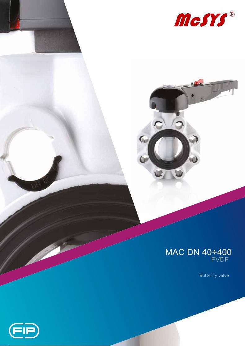
Ex: MACOCRM315F MAC butterfly valve, PVC-C disc, gear box, d 315, FPM gasket
CODESHOW TO READ VALVES COMMERCIAL CODES
2
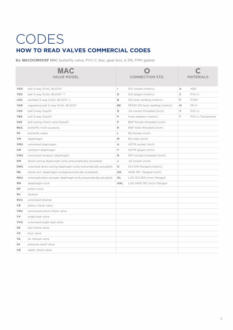
RMCOMMAND SYSTEM
315 SIZE
FSEAL
MATERIALMETRIC SERIES d (mm) INCH SERIES d/R (inches)SHX handle block (for VKD ball valves) 006 6 E EPDM
LM lever (for butterfly) 008 8 F FPM
RM gear box (for butterfly) 010 10 N NBR
FM bare shaft (for butterfly) 012 12 014 1/4” P PTFE
NC Pneumatic Normally Closed 016 16 038 3/8”
NO Pneumatic Normally Open 020 20 012 1/2”
DA Pneumatic Double Acting 025 25 034 3/4”
SA Pneumatic Single Acting 032 32 100 1”
EA Electric 230V AC 040 40 114 1” 1/4
EB Electric 115V AC 050 50 112 1” 1/2
EE Electric 24V AC 063 63 200 2”
EF Electric 24V DC 214 2” 1/4
EI Electric 400V trifase 075 75 212 2” 1/2
EM Electric 90-240V AC 234 2” 3/4
EL Electric 24V AC/DC 090 90 300 3”
110 110 400 4”
125 125
140 140 500 5”
160 160 600 6”
180 180
200 200
225 225 800 8”
250 250
280 280 810 10”
315 315 812 12”
355 355
400 400
813
814
14”
16”
3
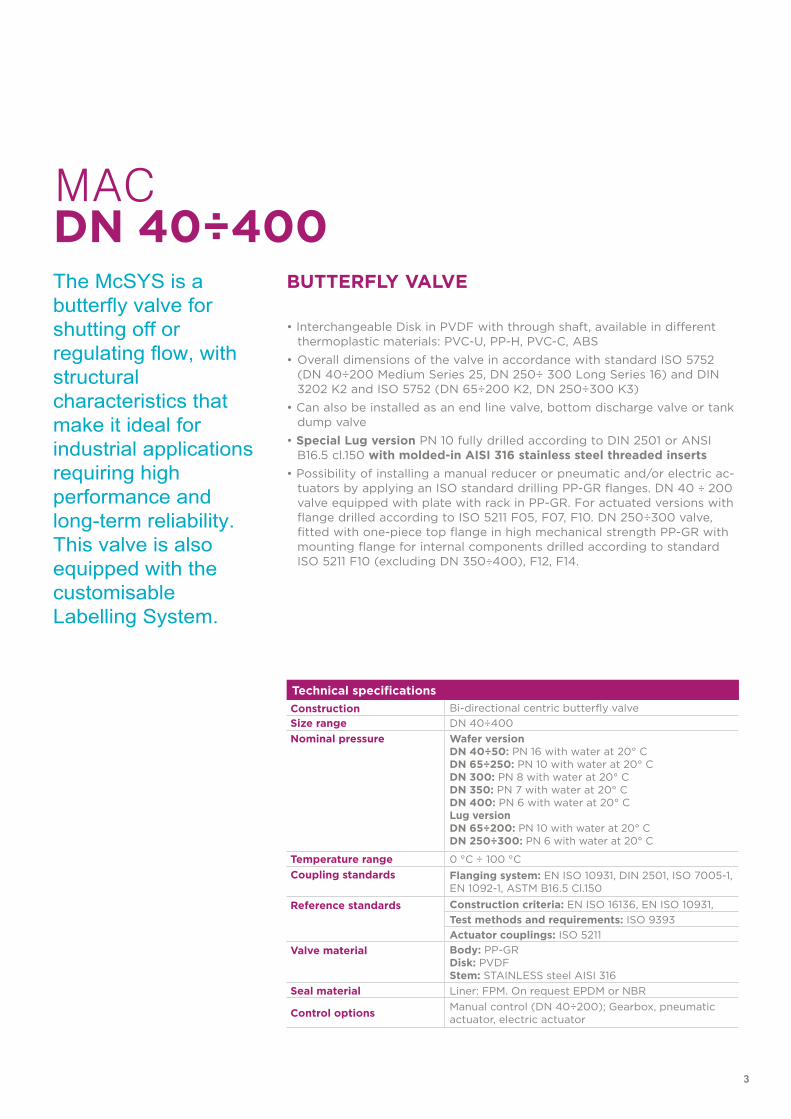
Technical specificationsConstruction Bi-directional centric butterfly valveSize range DN 40÷400Nominal pressure Wafer version
DN 40÷50: PN 16 with water at 20° CDN 65÷250: PN 10 with water at 20° CDN 300: PN 8 with water at 20° CDN 350: PN 7 with water at 20° CDN 400: PN 6 with water at 20° CLug version DN 65÷200: PN 10 with water at 20° CDN 250÷300: PN 6 with water at 20° C
Temperature range 0 °C ÷ 100 °CCoupling standards Flanging system: EN ISO 10931, DIN 2501, ISO 7005-1,
EN 1092-1, ASTM B16.5 Cl.150
Reference standards Construction criteria: EN ISO 16136, EN ISO 10931,Test methods and requirements: ISO 9393Actuator couplings: ISO 5211
Valve material Body: PP-GRDisk: PVDFStem: STAINLESS steel AISI 316
Seal material Liner: FPM. On request EPDM or NBR
Control options Manual control (DN 40÷200); Gearbox, pneumatic actuator, electric actuator
The McSYS is a butterfly valve for shutting off or regulating flow, with structural characteristics that make it ideal for industrial applications requiring high performance and long-term reliability. This valve is also equipped with the customisable Labelling System.
BUTTERFLY VALVE
• Interchangeable Disk in PVDF with through shaft, available in differentthermoplastic materials: PVC-U, PP-H, PVC-C, ABS
• Overall dimensions of the valve in accordance with standard ISO 5752(DN 40÷200 Medium Series 25, DN 250÷ 300 Long Series 16) and DIN3202 K2 and ISO 5752 (DN 65÷200 K2, DN 250÷300 K3)
• Can also be installed as an end line valve, bottom discharge valve or tankdump valve
• Special Lug version PN 10 fully drilled according to DIN 2501 or ANSIB16.5 cl.150 with molded-in AISI 316 stainless steel threaded inserts
• Possibility of installing a manual reducer or pneumatic and/or electric ac-tuators by applying an ISO standard drilling PP-GR flanges. DN 40 ÷ 200valve equipped with plate with rack in PP-GR. For actuated versions withflange drilled according to ISO 5211 F05, F07, F10. DN 250÷300 valve,fitted with one-piece top flange in high mechanical strength PP-GR withmounting flange for internal components drilled according to standardISO 5211 F10 (excluding DN 350÷400), F12, F14.
MACDN 40÷400
4
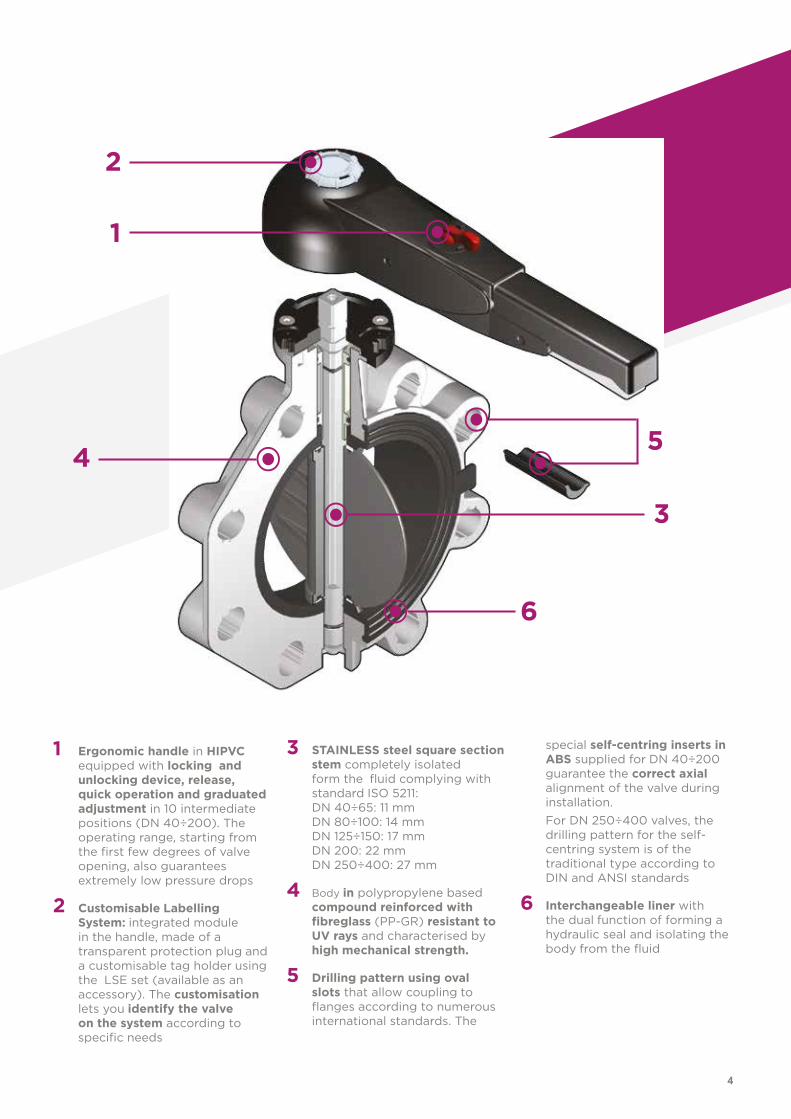
1 Ergonomic handle in HIPVCequipped with locking and unlocking device, release, quick operation and graduated adjustment in 10 intermediate positions (DN 40÷200). The operating range, starting from the first few degrees of valve opening, also guarantees extremely low pressure drops
2 Customisable LabellingSystem: integrated module in the handle, made of a transparent protection plug and a customisable tag holder using the LSE set (available as an accessory). The customisation lets you identify the valve on the system according to specific needs
3 STAINLESS steel square sectionstem completely isolated form the fluid complying with standard ISO 5211: DN 40÷65: 11 mmDN 80÷100: 14 mmDN 125÷150: 17 mmDN 200: 22 mmDN 250÷400: 27 mm
4 Body in polypropylene basedcompound reinforced with fibreglass (PP-GR) resistant to UV rays and characterised by high mechanical strength.
5 Drilling pattern using ovalslots that allow coupling to flanges according to numerous international standards. The
special self-centring inserts in ABS supplied for DN 40÷200 guarantee the correct axial alignment of the valve during installation.For DN 250÷400 valves, the drilling pattern for the self-centring system is of the traditional type according to DIN and ANSI standards
6 Interchangeable liner withthe dual function of forming a hydraulic seal and isolating the body from the fluid
2
3
1
4 5
6
5
TECHNICAL DATA
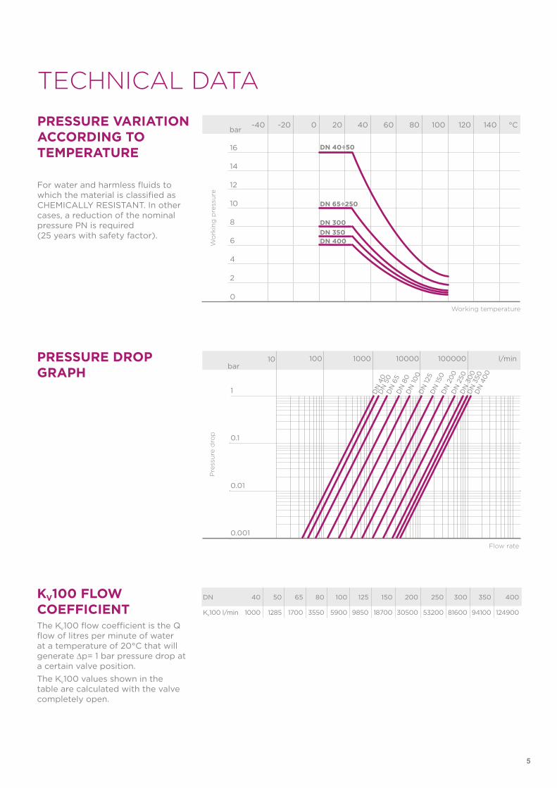
KV100 FLOW COEFFICIENTThe Kv100 flow coefficient is the Q flow of litres per minute of water at a temperature of 20°C that will generate ∆p= 1 bar pressure drop at a certain valve position.The Kv100 values shown in the table are calculated with the valve completely open.
PRESSURE DROP GRAPH
-40 -20 0 20 40 60 80 100 120 140 °C
16
14
12
10
8
6
4
2
0
Wo
rkin
g p
ress
ure
Working temperature
barPRESSURE VARIATION ACCORDING TO TEMPERATURE
For water and harmless fluids to which the material is classified as CHEMICALLY RESISTANT. In other cases, a reduction of the nominal pressure PN is required (25 years with safety factor).
DN 40÷50
DN 65÷250
DN 300DN 350DN 400
DN 40 50 65 80 100 125 150 200 250 300 350 400
Kv100 l/min 1000 1285 1700 3550 5900 9850 18700 30500 53200 81600 94100 124900
Pre
ssu
re d
rop
Flow rate
bar10 100 1000 10000 100000 l/min
1
0.1
0.01
0.001
DN
40
DN
50
DN
65
DN
80
DN
100
DN
125
DN
150
DN
20
0D
N 2
50D
N 3
00
DN
350
DN
40
0
6
The information in this leaflet is provided in good faith. No liability will be accepted concerning technical data that is not directly covered by recognised international standards. FIP reserves the right to carry out any modification. Products must be installed and maintained by qualified personnel.
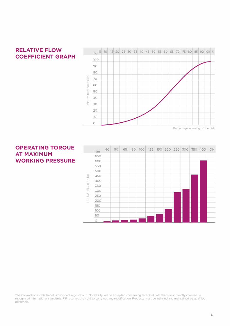
OPERATING TORQUE AT MAXIMUM WORKING PRESSURE
RELATIVE FLOW COEFFICIENT GRAPH
5 10 15 20 25 30 35 40 45 50 55 60 65 70 75 80 85 90 100 %
100
90
80
70
60
50
40
30
20
10
0
Rel
ativ
e fl
ow
co
effici
ent
Percentage opening of the disk
%
DN 40 50 65 80 100 125 150 200 250 300 350 400
Kv100 l/min 1000 1285 1700 3550 5900 9850 18700 30500 53200 81600 94100 124900
40 50 65 80 100 125 150 200 250 300 350 400 DN
650
600
550
500
450
400
350
300
250
200
150
100
50
0
OP
ER
AT
ING
TO
RQ
UE
Nm
7
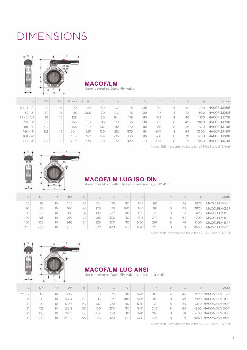
DIMENSIONS
d - Size DN PN A min A max B2 B3 C C1 H U Z g Code
50 - 1” 1/2 40 16 99 109 60 137 175 100 132 4 33 1000 MACOFLM050F
63 - 2” 50 16 115 125.5 70 143 175 100 147 4 43 1180 MACOFLM063F75 - 2” 1/2 65 10 128 144 80 164 175 110 165 4 46 1570 MACOFLM075F
90 - 3” 80 10 145 160 93 178 175 100 185 8 49 2020 MACOFLM090F110 - 4” 100 10 165 190 107 192 272 110 211 8 56 2370 MACOFLM110F140 - 5” 125 10 204 215 120 212 330 110 240 8 64 3300 MACOFLM140F160 - 6” 150 10 230 242 134 225 330 110 268 8 70 4100 MACOFLM160F225 - 8” 200 10 280 298 161 272 420 122 323 8 71 7050 MACOFLM225F
MACOF/LMHand operated Butterfly valve
Note: NBR liners are available for d75÷225 and 2” 1/2÷8”
Note: NBR liners are available for d75÷225 and 2” 1/2÷8”
d DN PN øA B2 B3 C C1 f H U Z g Code
75 65 10 145 80 164 175 110 M16 165 4 46 1970 MACOLFLM075F
90 80 10 160 93 178 175 100 M16 185 8 49 2820 MACOLFLM090F110 100 10 180 107 192 272 110 M16 211 8 56 3170 MACOLFLM110F
140 125 10 210 120 212 330 110 M16 240 8 64 4900 MACOLFLM140F160 150 10 240 134 225 330 110 M20 268 8 70 5700 MACOLFLM160F225 200 10 295 161 272 420 122 M20 323 8 71 8650 MACOLFLM225F
MACOF/LM LUG ISO-DINHand operated butterfly valve, version Lug ISO-DIN
Note: NBR liners are available for d75÷225 and 2” 1/2÷8”
d DN PN øA B2 B3 C C1 f H U Z g Code
2” 1/2 65 10 139.7 119 80 175 110 5/8” 165 4 46 1970 MACOALFLM212F
3” 80 10 152.4 133 93 175 100 5/8” 185 8 49 2820 MACOALFLM300F4” 100 10 190.5 147 107 272 110 5/8” 211 8 56 3170 MACOALFLM400F5” 125 10 215.9 167 120 330 110 3/4” 240 8 64 4900 MACOALFLM500F6” 150 10 241.3 180 134 330 110 3/4” 268 8 70 5700 MACOALFLM600F8” 200 10 298.4 227 161 420 122 3/4” 323 8 71 8650 MACOALFLM800F
MACOF/LM LUG ANSIHand operated Butterfly valve, version Lug ANSI
8
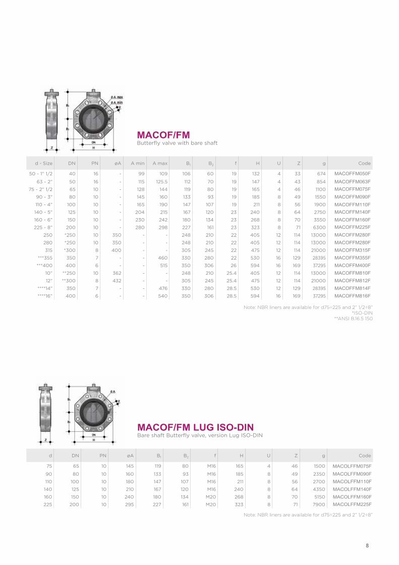
d - Size DN PN øA A min A max B1 B2 f H U Z g Code
50 - 1” 1/2 40 16 - 99 109 106 60 19 132 4 33 674 MACOFFM050F
63 - 2” 50 16 - 115 125.5 112 70 19 147 4 43 854 MACOFFM063F75 - 2” 1/2 65 10 - 128 144 119 80 19 165 4 46 1100 MACOFFM075F
90 - 3” 80 10 - 145 160 133 93 19 185 8 49 1550 MACOFFM090F110 - 4” 100 10 - 165 190 147 107 19 211 8 56 1900 MACOFFM110F140 - 5” 125 10 - 204 215 167 120 23 240 8 64 2750 MACOFFM140F160 - 6” 150 10 - 230 242 180 134 23 268 8 70 3550 MACOFFM160F225 - 8” 200 10 - 280 298 227 161 23 323 8 71 6300 MACOFFM225F
250 *250 10 350 - - 248 210 22 405 12 114 13000 MACOFFM280F280 *250 10 350 - - 248 210 22 405 12 114 13000 MACOFFM280F315 *300 8 400 - - 305 245 22 475 12 114 21000 MACOFFM315F
***355 350 7 - - 460 330 280 22 530 16 129 28395 MACOFFM355F***400 400 6 - - 515 350 306 26 594 16 169 37295 MACOFFM400F
10” **250 10 362 - - 248 210 25.4 405 12 114 13000 MACOFFM810F12” **300 8 432 - - 305 245 25.4 475 12 114 21000 MACOFFM812F
****14” 350 7 - - 476 330 280 28.5 530 12 129 28395 MACOFFM814F****16” 400 6 - - 540 350 306 28.5 594 16 169 37295 MACOFFM816F
MACOF/FMButterfly valve with bare shaft
Note: NBR liners are available for d75÷225 and 2” 1/2÷8”*ISO-DIN
**ANSI B.16.5 150
d DN PN øA B1 B2 f H U Z g Code
75 65 10 145 119 80 M16 165 4 46 1500 MACOLFFM075F
90 80 10 160 133 93 M16 185 8 49 2350 MACOLFFM090F110 100 10 180 147 107 M16 211 8 56 2700 MACOLFFM110F
140 125 10 210 167 120 M16 240 8 64 4350 MACOLFFM140F160 150 10 240 180 134 M20 268 8 70 5150 MACOLFFM160F225 200 10 295 227 161 M20 323 8 71 7900 MACOLFFM225F
MACOF/FM LUG ISO-DINBare shaft Butterfly valve, version Lug ISO-DIN
Note: NBR liners are available for d75÷225 and 2” 1/2÷8”
9
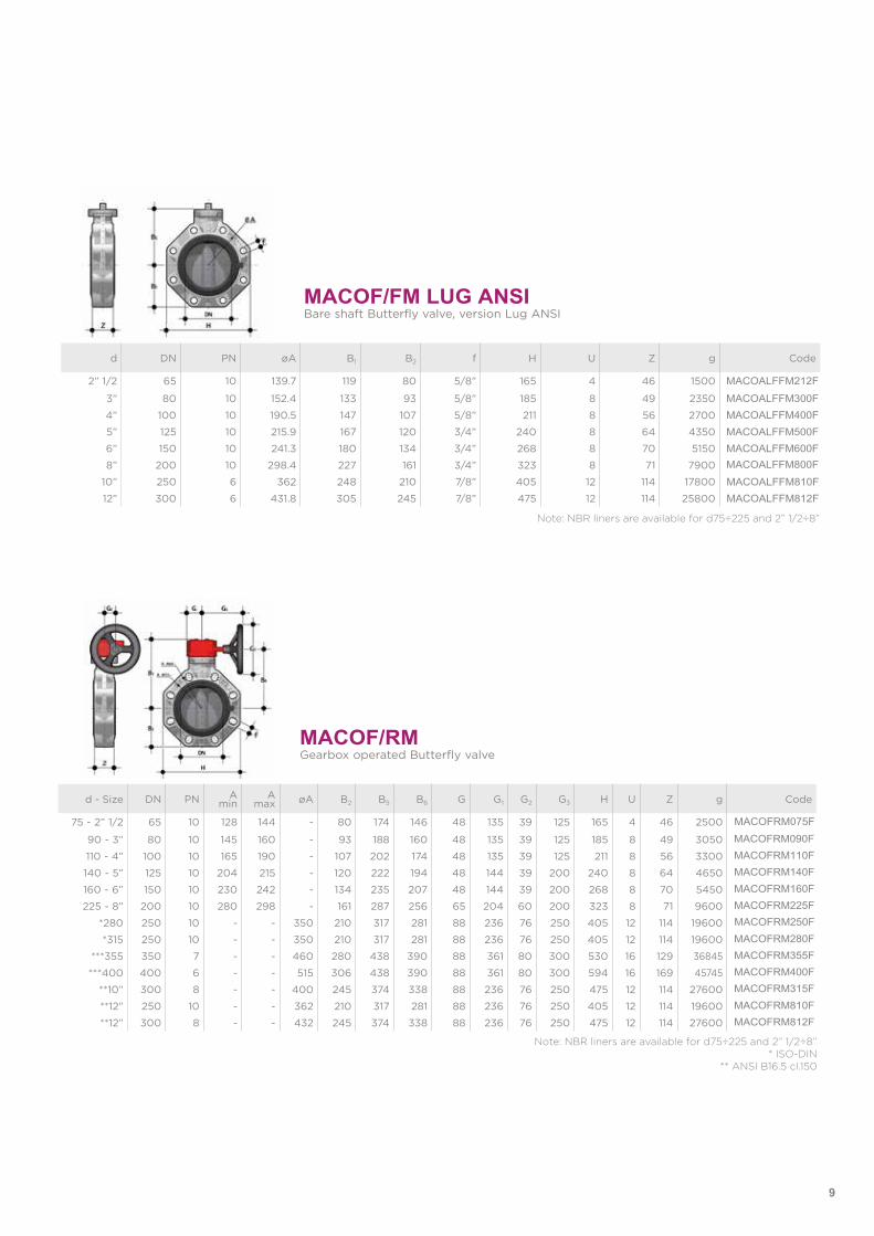
MACOF/RMGearbox operated Butterfly valve
d - Size DN PN A min
A max øA B2 B5 B6 G G1 G2 G3 H U Z g Code
75 - 2” 1/2 65 10 128 144 - 80 174 146 48 135 39 125 165 4 46 2500 MACOFRM075F
90 - 3” 80 10 145 160 - 93 188 160 48 135 39 125 185 8 49 3050 MACOFRM090F
110 - 4” 100 10 165 190 - 107 202 174 48 135 39 125 211 8 56 3300 MACOFRM110F
140 - 5” 125 10 204 215 - 120 222 194 48 144 39 200 240 8 64 4650 MACOFRM140F
160 - 6” 150 10 230 242 - 134 235 207 48 144 39 200 268 8 70 5450 MACOFRM160F
225 - 8” 200 10 280 298 - 161 287 256 65 204 60 200 323 8 71 9600 MACOFRM225F
*280 250 10 - - 350 210 317 281 88 236 76 250 405 12 114 19600 MACOFRM250F
*315 250 10 - - 350 210 317 281 88 236 76 250 405 12 114 19600 MACOFRM280F
***355 350 7 - - 460 280 438 390 88 361 80 300 530 16 129 36845 MACOFRM355F
***400 400 6 - - 515 306 438 390 88 361 80 300 594 16 169 45745 MACOFRM400F
**10” 300 8 - - 400 245 374 338 88 236 76 250 475 12 114 27600 MACOFRM315F
**12” 250 10 - - 362 210 317 281 88 236 76 250 405 12 114 19600 MACOFRM810F
**12” 300 8 - - 432 245 374 338 88 236 76 250 475 12 114 27600 MACOFRM812F
Note: NBR liners are available for d75÷225 and 2” 1/2÷8”* ISO-DIN
** ANSI B16.5 cl.150
d DN PN øA B1 B2 f H U Z g Code
2” 1/2 65 10 139.7 119 80 5/8” 165 4 46 1500 MACOALFFM212F
3” 80 10 152.4 133 93 5/8” 185 8 49 2350 MACOALFFM300F4” 100 10 190.5 147 107 5/8” 211 8 56 2700 MACOALFFM400F5” 125 10 215.9 167 120 3/4” 240 8 64 4350 MACOALFFM500F6” 150 10 241.3 180 134 3/4” 268 8 70 5150 MACOALFFM600F8” 200 10 298.4 227 161 3/4” 323 8 71 7900 MACOALFFM800F
10” 250 6 362 248 210 7/8” 405 12 114 17800 MACOALFFM810F12” 300 6 431.8 305 245 7/8” 475 12 114 25800 MACOALFFM812F
MACOF/FM LUG ANSIBare shaft Butterfly valve, version Lug ANSI
Note: NBR liners are available for d75÷225 and 2” 1/2÷8”
10
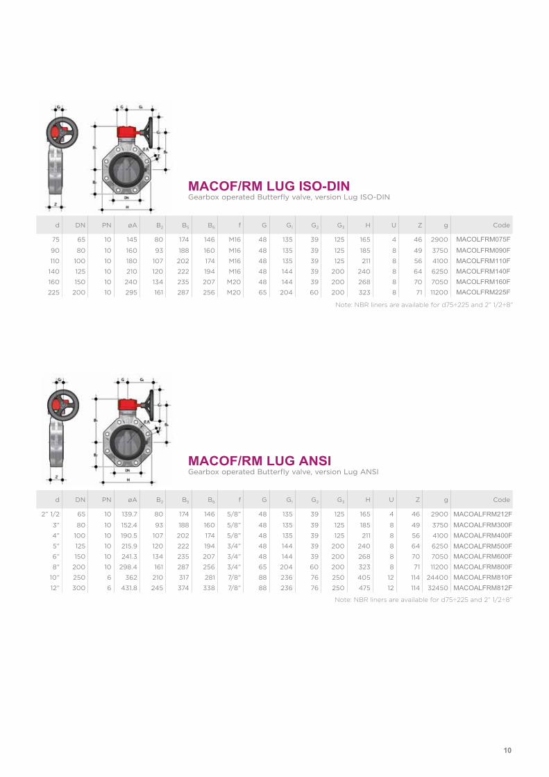
MACOF/RM LUG ISO-DINGearbox operated Butterfly valve, version Lug ISO-DIN
d DN PN øA B2 B5 B6 f G G1 G2 G3 H U Z g Code
75 65 10 145 80 174 146 M16 48 135 39 125 165 4 46 2900 MACOLFRM075F
90 80 10 160 93 188 160 M16 48 135 39 125 185 8 49 3750 MACOLFRM090F110 100 10 180 107 202 174 M16 48 135 39 125 211 8 56 4100 MACOLFRM110F
140 125 10 210 120 222 194 M16 48 144 39 200 240 8 64 6250 MACOLFRM140F160 150 10 240 134 235 207 M20 48 144 39 200 268 8 70 7050 MACOLFRM160F225 200 10 295 161 287 256 M20 65 204 60 200 323 8 71 11200 MACOLFRM225F
Note: NBR liners are available for d75÷225 and 2” 1/2÷8”
MACOF/RM LUG ANSIGearbox operated Butterfly valve, version Lug ANSI
d DN PN øA B2 B5 B6 f G G1 G2 G3 H U Z g Code
2” 1/2 65 10 139.7 80 174 146 5/8” 48 135 39 125 165 4 46 2900 MACOALFRM212F
3” 80 10 152.4 93 188 160 5/8” 48 135 39 125 185 8 49 3750 MACOALFRM300F4” 100 10 190.5 107 202 174 5/8” 48 135 39 125 211 8 56 4100 MACOALFRM400F5” 125 10 215.9 120 222 194 3/4” 48 144 39 200 240 8 64 6250 MACOALFRM500F6” 150 10 241.3 134 235 207 3/4” 48 144 39 200 268 8 70 7050 MACOALFRM600F8” 200 10 298.4 161 287 256 3/4” 65 204 60 200 323 8 71 11200 MACOALFRM800F
10” 250 6 362 210 317 281 7/8” 88 236 76 250 405 12 114 24400 MACOALFRM810F12” 300 6 431.8 245 374 338 7/8” 88 236 76 250 475 12 114 32450 MACOALFRM812F
Note: NBR liners are available for d75÷225 and 2” 1/2÷8”
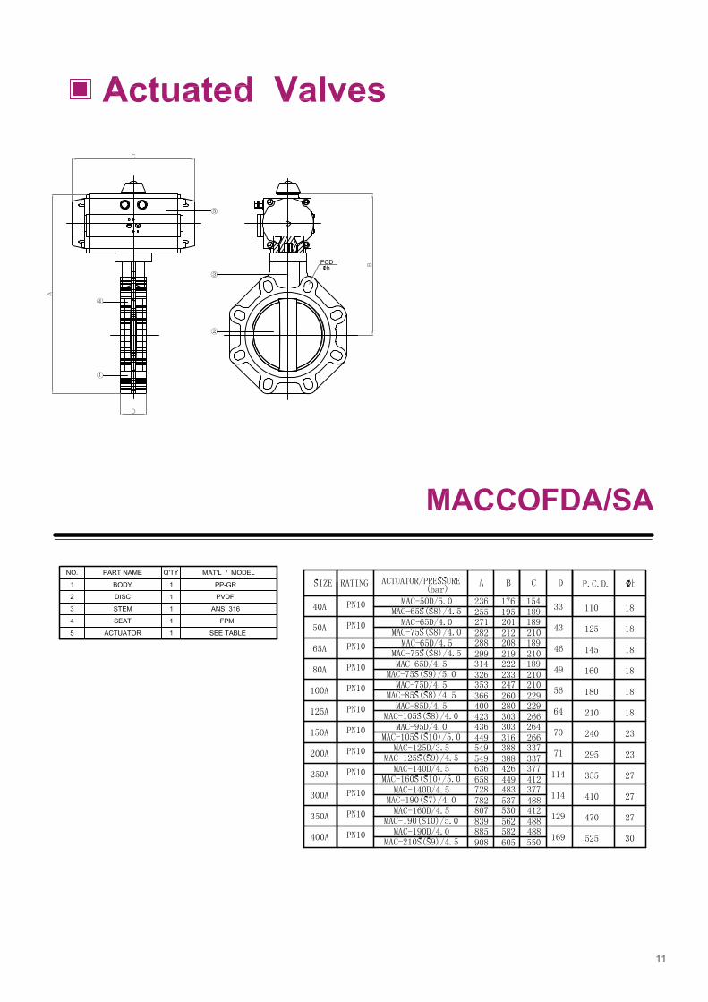
11
12
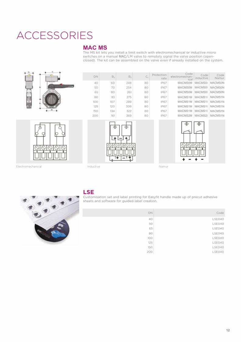
MAC MS
LSE
ACCESSORIESThe MS kit lets you install a limit switch with electromechanical or inductive micro switches on a manual MAC/LM valve to remotely signal the valve position (open-closed). The kit can be assembled on the valve even if already installed on the system.
Customisation set and label printing for Easyfit handle made up of precut adhesive sheets and software for guided label creation.
DN B2 B3 C1Protection
rate
Codeelectromechan-
icalCode
inductiveCode
Namur
40 60 248 80 IP67 MACMS0M MACMS0I MACMS0N
50 70 254 80 IP67 MACMS0M MACMS0I MACMS0N65 80 261 80 IP67 MACMS0M MACMS0I MACMS0N
80 93 275 80 IP67 MACMS1M MACMS1I MACMS1N100 107 289 80 IP67 MACMS1M MACMS1I MACMS1N125 120 309 80 IP67 MACMS1M MACMS1I MACMS1N150 134 322 80 IP67 MACMS1M MACMS1I MACMS1N
200 161 369 80 IP67 MACMS2M MACMS2I MACMS1N
DN Code
40 LSE040
50 LSE040
65 LSE040
80 LSE040
100 LSE040
125 LSE040
150 LSE040
200 LSE040
Electromechanical Inductive Namur
13
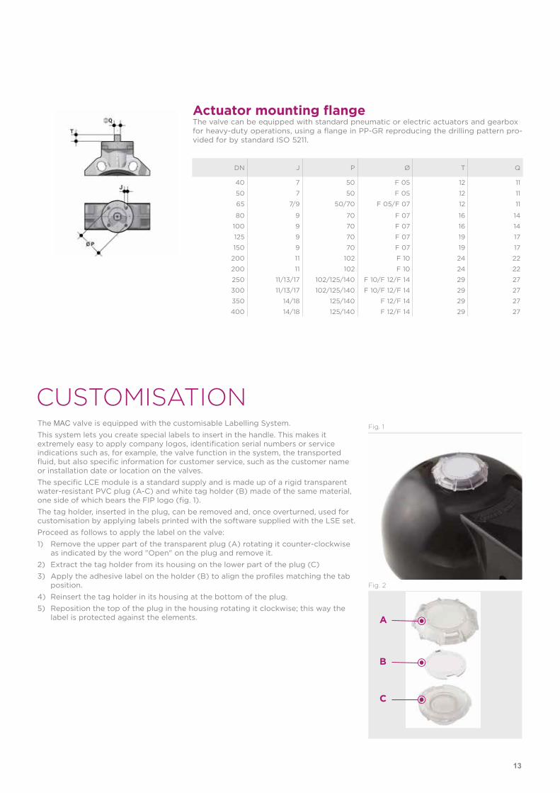
Actuator mounting flangeThe valve can be equipped with standard pneumatic or electric actuators and gearbox for heavy-duty operations, using a flange in PP-GR reproducing the drilling pattern pro-vided for by standard ISO 5211.
CUSTOMISATIONThe MAC valve is equipped with the customisable Labelling System.This system lets you create special labels to insert in the handle. This makes it extremely easy to apply company logos, identification serial numbers or service indications such as, for example, the valve function in the system, the transported fluid, but also specific information for customer service, such as the customer name or installation date or location on the valves.The specific LCE module is a standard supply and is made up of a rigid transparent water-resistant PVC plug (A-C) and white tag holder (B) made of the same material, one side of which bears the FIP logo (fig. 1).The tag holder, inserted in the plug, can be removed and, once overturned, used for customisation by applying labels printed with the software supplied with the LSE set. Proceed as follows to apply the label on the valve:1) Remove the upper part of the transparent plug (A) rotating it counter-clockwise
as indicated by the word "Open" on the plug and remove it.2) Extract the tag holder from its housing on the lower part of the plug (C)3) Apply the adhesive label on the holder (B) to align the profiles matching the tab
position.4) Reinsert the tag holder in its housing at the bottom of the plug.5) Reposition the top of the plug in the housing rotating it clockwise; this way the
label is protected against the elements.
Fig. 1
Fig. 2
A
B
C
DN J P Ø T Q
40 7 50 F 05 12 11
50 7 50 F 05 12 11
65 7/9 50/70 F 05/F 07 12 11
80 9 70 F 07 16 14
100 9 70 F 07 16 14
125 9 70 F 07 19 17
150 9 70 F 07 19 17
200 11 102 F 10 24 22
200 11 102 F 10 24 22
250 11/13/17 102/125/140 F 10/F 12/F 14 29 27
300 11/13/17 102/125/140 F 10/F 12/F 14 29 27
350 14/18 125/140 F 12/F 14 29 27
400 14/18 125/140 F 12/F 14 29 27
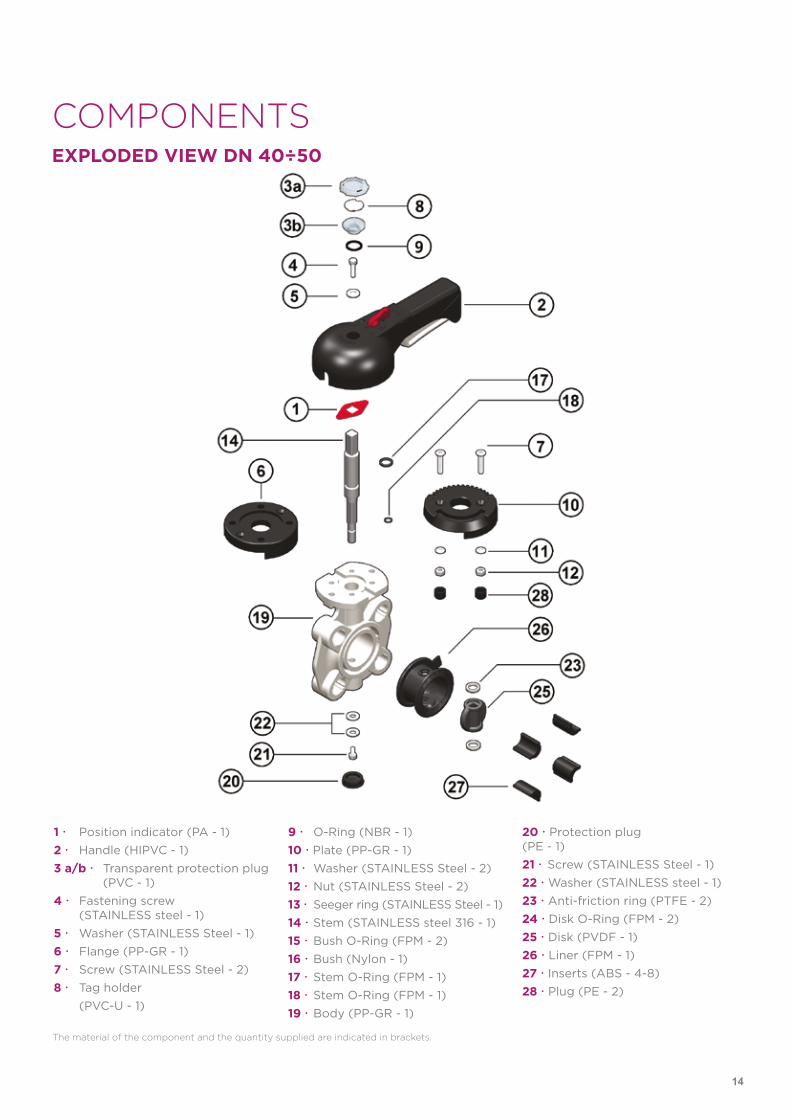
COMPONENTSEXPLODED VIEW DN 40÷50
The material of the component and the quantity supplied are indicated in brackets.
1 Position indicator (PA - 1)2 Handle (HIPVC - 1)3 a/b Transparent protection plug
(PVC - 1)4 Fastening screw
(STAINLESS steel - 1)5 Washer (STAINLESS Steel - 1)6 Flange (PP-GR - 1)7 Screw (STAINLESS Steel - 2)8 Tag holder
(PVC-U - 1)
9 O-Ring (NBR - 1)10 Plate (PP-GR - 1)11 Washer (STAINLESS Steel - 2)12 Nut (STAINLESS Steel - 2)13 Seeger ring (STAINLESS Steel - 1)14 Stem (STAINLESS steel 316 - 1)15 Bush O-Ring (FPM - 2)16 Bush (Nylon - 1)17 Stem O-Ring (FPM - 1)18 Stem O-Ring (FPM - 1)19 Body (PP-GR - 1)
20 Protection plug (PE - 1)21 Screw (STAINLESS Steel - 1)22 Washer (STAINLESS steel - 1)23 Anti-friction ring (PTFE - 2)24 Disk O-Ring (FPM - 2)25 Disk (PVDF - 1)26 Liner (FPM - 1)27 Inserts (ABS - 4-8)28 Plug (PE - 2)
14
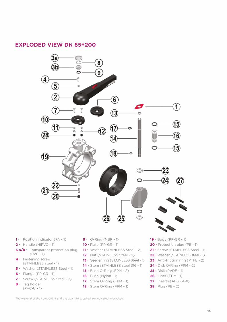
EXPLODED VIEW DN 65÷200
1 Position indicator (PA - 1)2 Handle (HIPVC - 1)3 a/b Transparent protection plug
(PVC - 1)4 Fastening screw
(STAINLESS steel - 1)5 Washer (STAINLESS Steel - 1)6 Flange (PP-GR - 1)7 Screw (STAINLESS Steel - 2)8 Tag holder
(PVC-U - 1)
9 O-Ring (NBR - 1)10 Plate (PP-GR - 1)11 Washer (STAINLESS Steel - 2)12 Nut (STAINLESS Steel - 2)13 Seeger ring (STAINLESS Steel - 1)14 Stem (STAINLESS steel 316 - 1)15 Bush O-Ring (FPM - 2)16 Bush (Nylon - 1)17 Stem O-Ring (FPM - 1)18 Stem O-Ring (FPM - 1)
19 Body (PP-GR - 1)20 Protection plug (PE - 1)21 Screw (STAINLESS Steel - 1)22 Washer (STAINLESS steel - 1)23 Anti-friction ring (PTFE - 2)24 Disk O-Ring (FPM - 2)25 Disk (PVDF - 1)26 Liner (FPM - 1)27 Inserts (ABS - 4-8)28 Plug (PE - 2)
The material of the component and the quantity supplied are indicated in brackets.
15
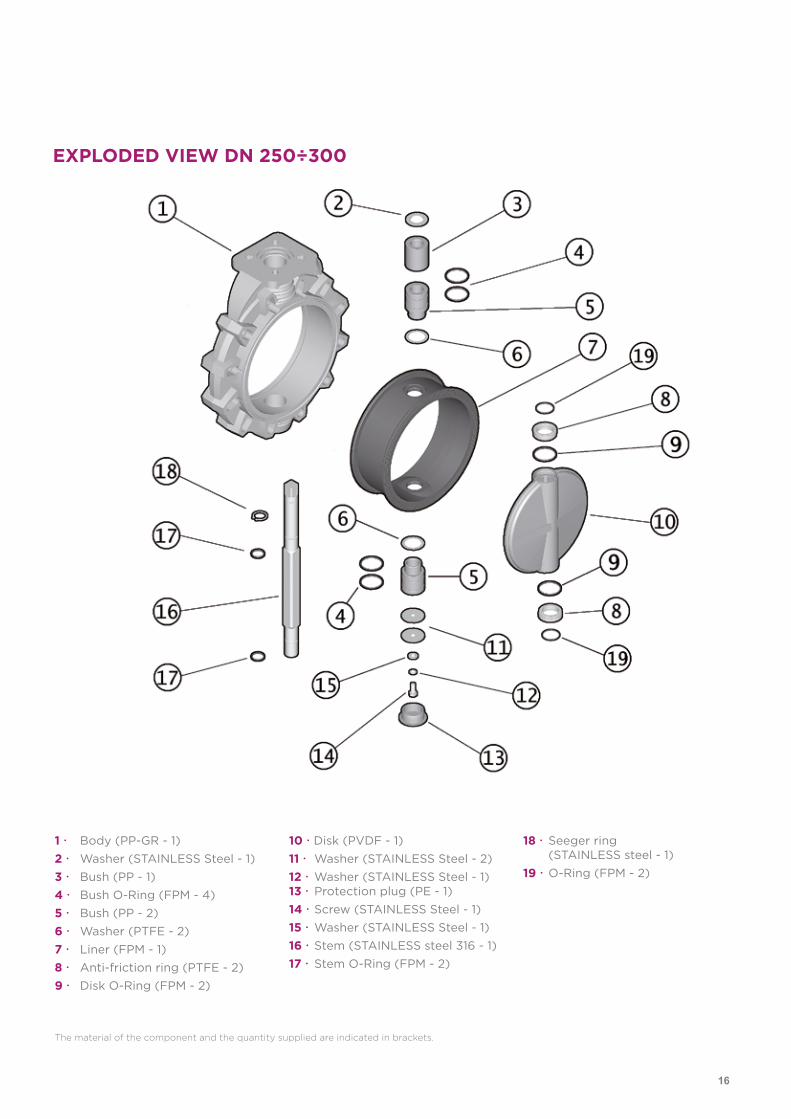
EXPLODED VIEW DN 250÷300
1 Body (PP-GR - 1)2 Washer (STAINLESS Steel - 1)3 Bush (PP - 1)4 Bush O-Ring (FPM - 4)5 Bush (PP - 2)6 Washer (PTFE - 2)7 Liner (FPM - 1)8 Anti-friction ring (PTFE - 2)9 Disk O-Ring (FPM - 2)
10 Disk (PVDF - 1)11 Washer (STAINLESS Steel - 2)12 Washer (STAINLESS Steel - 1)13 Protection plug (PE - 1)14 Screw (STAINLESS Steel - 1)15 Washer (STAINLESS Steel - 1)16 Stem (STAINLESS steel 316 - 1)17 Stem O-Ring (FPM - 2)
18 Seeger ring (STAINLESS steel - 1)19 O-Ring (FPM - 2)
The material of the component and the quantity supplied are indicated in brackets.
16
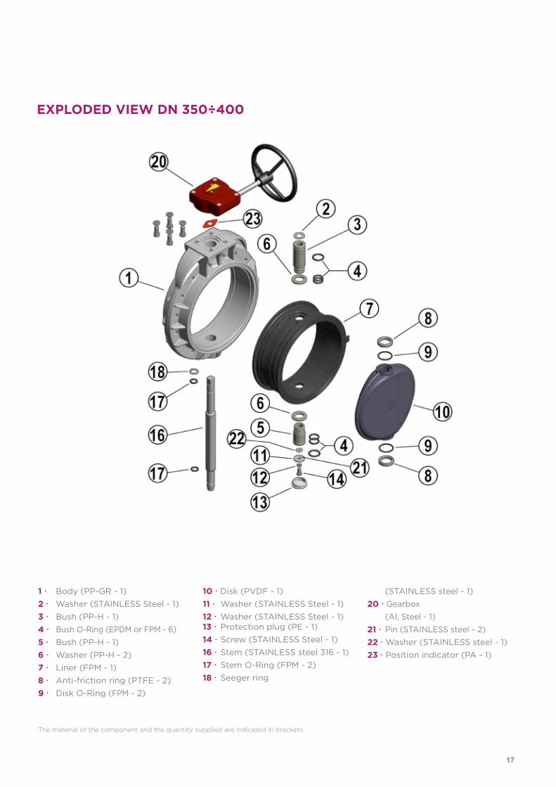
EXPLODED VIEW DN 350÷400
1 Body (PP-GR - 1)2 Washer (STAINLESS Steel - 1)3 Bush (PP-H - 1)4 Bush O-Ring (EPDM or FPM - 6)5 Bush (PP-H - 1)6 Washer (PP-H - 2)7 Liner (FPM - 1)8 Anti-friction ring (PTFE - 2)9 Disk O-Ring (FPM - 2)
10 Disk (PVDF - 1)11 Washer (STAINLESS Steel - 1)12 Washer (STAINLESS Steel - 1)13 Protection plug (PE - 1)14 Screw (STAINLESS Steel - 1)16 Stem (STAINLESS steel 316 - 1)17 Stem O-Ring (FPM - 2)18 Seeger ring
(STAINLESS steel - 1)20 Gearbox (Al, Steel - 1)21 Pin (STAINLESS steel - 2)22 Washer (STAINLESS steel - 1)23 Position indicator (PA - 1)
The material of the component and the quantity supplied are indicated in brackets.
17
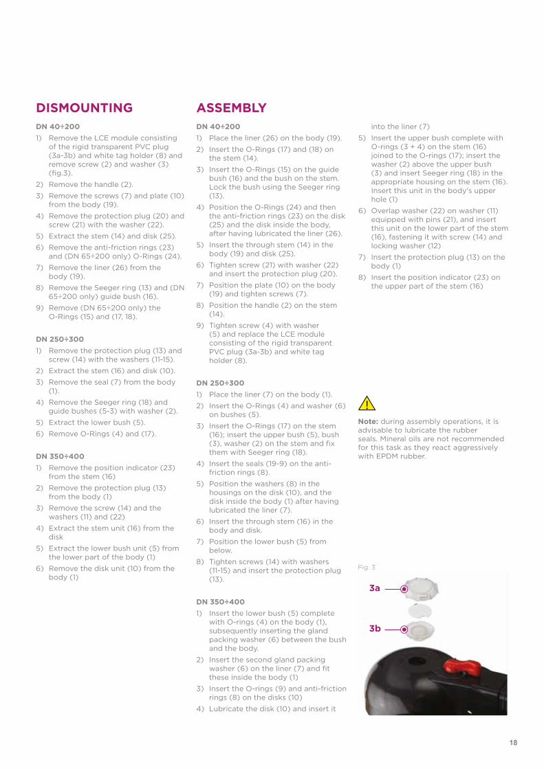
DISMOUNTING ASSEMBLYDN 40÷200 1) Place the liner (26) on the body (19).
2) Insert the O-Rings (17) and (18) onthe stem (14).
3) Insert the O-Rings (15) on the guidebush (16) and the bush on the stem.Lock the bush using the Seeger ring(13).
4) Position the O-Rings (24) and thenthe anti-friction rings (23) on the disk(25) and the disk inside the body,after having lubricated the liner (26).
5) Insert the through stem (14) in thebody (19) and disk (25).
6) Tighten screw (21) with washer (22)and insert the protection plug (20).
7) Position the plate (10) on the body(19) and tighten screws (7).
8) Position the handle (2) on the stem(14).
9) Tighten screw (4) with washer(5) and replace the LCE moduleconsisting of the rigid transparentPVC plug (3a-3b) and white tagholder (8).
DN 250÷300 1) Place the liner (7) on the body (1).
2) Insert the O-Rings (4) and washer (6)on bushes (5).
3) Insert the O-Rings (17) on the stem(16); insert the upper bush (5), bush(3), washer (2) on the stem and fixthem with Seeger ring (18).
4) Insert the seals (19-9) on the anti-friction rings (8).
5) Position the washers (8) in thehousings on the disk (10), and thedisk inside the body (1) after havinglubricated the liner (7).
6) Insert the through stem (16) in thebody and disk.
7) Position the lower bush (5) frombelow.
8) Tighten screws (14) with washers(11-15) and insert the protection plug(13).
DN 350÷4001) Insert the lower bush (5) complete
with O-rings (4) on the body (1),subsequently inserting the glandpacking washer (6) between the bushand the body.
2) Insert the second gland packingwasher (6) on the liner (7) and fitthese inside the body (1)
3) Insert the O-rings (9) and anti-frictionrings (8) on the disks (10)
4) Lubricate the disk (10) and insert it
Note: during assembly operations, it is advisable to lubricate the rubberseals. Mineral oils are not recommendedfor this task as they react aggressively with EPDM rubber.
DN 40÷200 1) Remove the LCE module consisting
of the rigid transparent PVC plug(3a-3b) and white tag holder (8) andremove screw (2) and washer (3)(fig.3).
2) Remove the handle (2).
3) Remove the screws (7) and plate (10)from the body (19).
4) Remove the protection plug (20) andscrew (21) with the washer (22).
5) Extract the stem (14) and disk (25).
6) Remove the anti-friction rings (23)and (DN 65÷200 only) O-Rings (24).
7) Remove the liner (26) from thebody (19).
8) Remove the Seeger ring (13) and (DN65÷200 only) guide bush (16).
9) Remove (DN 65÷200 only) theO-Rings (15) and (17, 18).
DN 250÷300 1) Remove the protection plug (13) and
screw (14) with the washers (11-15).
2) Extract the stem (16) and disk (10).
3) Remove the seal (7) from the body(1).
4) Remove the Seeger ring (18) andguide bushes (5-3) with washer (2).
5) Extract the lower bush (5).
6) Remove O-Rings (4) and (17).
DN 350÷400 1) Remove the position indicator (23)
from the stem (16)
2) Remove the protection plug (13)from the body (1)
3) Remove the screw (14) and thewashers (11) and (22)
4) Extract the stem unit (16) from thedisk
5) Extract the lower bush unit (5) fromthe lower part of the body (1)
6) Remove the disk unit (10) from thebody (1)
into the liner (7)
5) Insert the upper bush complete withO-rings (3 + 4) on the stem (16)joined to the O-rings (17); insert thewasher (2) above the upper bush(3) and insert Seeger ring (18) in theappropriate housing on the stem (16).Insert this unit in the body's upperhole (1)
6) Overlap washer (22) on washer (11)equipped with pins (21), and insertthis unit on the lower part of the stem(16), fastening it with screw (14) andlocking washer (12)
7) Insert the protection plug (13) on thebody (1)
8) Insert the position indicator (23) onthe upper part of the stem (16)
Fig. 3
3a
3b
18
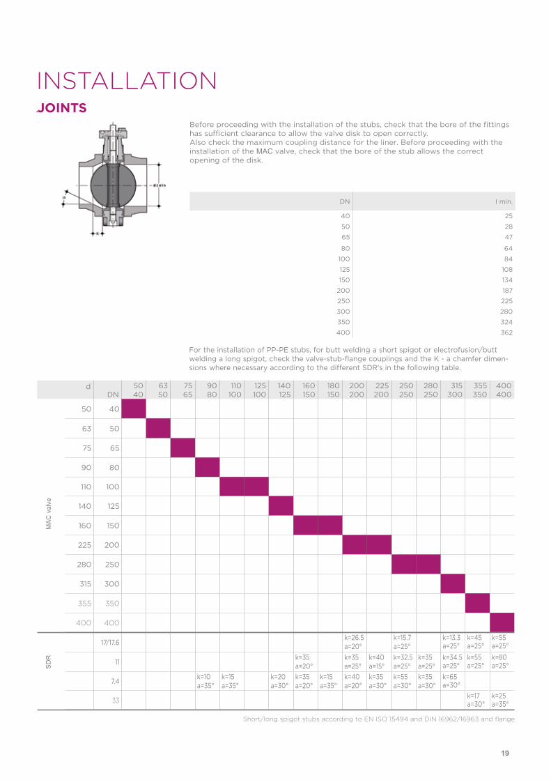
INSTALLATIONJOINTS
Before proceeding with the installation of the stubs, check that the bore of the fittings has sufficient clearance to allow the valve disk to open correctly. Also check the maximum coupling distance for the liner. Before proceeding with the installation of the MAC valve, check that the bore of the stub allows the correct opening of the disk.
DN I min.
40 25
50 28
65 47
80 64
100 84
125 108
150 134
200 187
250 225
300 280
350 324
400 362
JOINTS
For the installation of PP-PE stubs, for butt welding a short spigot or electrofusion/butt welding a long spigot, check the valve-stub-flange couplings and the K - a chamfer dimen-sions where necessary according to the different SDR's in the following table.
Short/long spigot stubs according to EN ISO 15494 and DIN 16962/16963 and flange
dDN
5040
6350
7565
9080
110100
125100
140125
160150
180150
200200
225200
250250
280250
315300
355350
400400
50 40
63 50
75 65
90 80
110 100
140 125
160 150
225 200
280 250
315 300
355 350
400 400
17/17.6k=26.5a=20°
k=15.7a=25°
k=13.3a=25°
k=45a=25°
k=55a=25°
11k=35a=20°
k=35a=25°
k=40a=15°
k=32.5a=25°
k=35a=25°
k=34.5a=25°
k=55a=25°
k=80a=25°
7.4k=10a=35°
k=15a=35°
k=20a=30°
k=35a=20°
k=15a=35°
k=40a=20°
k=35a=30°
k=55a=30°
k=35a=30°
k=65a=30°
33k=17a=30°
k=25a=35°
MA
C v
alve
SD
R
19
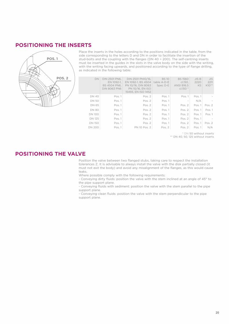
POSITIONING THE INSERTS
POS. 1
POS. 2
Place the inserts in the holes according to the positions indicated in the table, from the side corresponding to the letters D and DN in order to facilitate the insertion of the stud-bolts and the coupling with the flanges (DN 40 ÷ 200). The self-centring inserts must be inserted in the guides in the slots in the valve body on the side with the writing, with the writing facing upwards, and positioned according to the type of flange drilling, as indicated in the following table:
DN DIN 2501 PN6, EN 1092-1,
BS 4504 PN6, DIN 8063 PN6
DIN 2501 PN10/16, EN 1092-1, BS 4504 PN 10/16, DIN 8063
PN 10/16, EN ISO 15493, EN ISO 1452
BS 10 table A-D-E
Spec D-E
BS 1560 cl.150,
ANSI B16.5 cl.150 *
JIS B 2220
K5
JIS 2211
K10**
DN 40 Pos. 1 Pos. 2 Pos. 1 Pos. 1 Pos. 1 -
DN 50 Pos. 1 Pos. 2 Pos. 1 - N/A -
DN 65 Pos. 1 Pos. 2 Pos. 1 Pos. 2 Pos. 1 Pos. 2
DN 80 Pos. 1 Pos. 2 Pos. 1 Pos. 2 Pos. 1 Pos. 1
DN 100 Pos. 1 Pos. 2 Pos. 1 Pos. 2 Pos. 1 Pos. 1
DN 125 Pos. 1 Pos. 2 Pos. 1 Pos. 2 Pos. 1 -
DN 150 Pos. 1 Pos. 2 Pos. 1 Pos. 2 Pos. 1 Pos. 2
DN 200 Pos. 1 PN 10 Pos. 2 Pos. 2 Pos. 2 Pos. 1 N/A
* DN 50 without inserts** DN 40, 50, 125 without inserts
POSITIONING THE VALVEPosition the valve between two flanged stubs, taking care to respect the installation tolerances Z. It is advisable to always install the valve with the disk partially closed (it must not exit the body) and avoid any misalignment of the flanges, as this would cause leaks.Where possible comply with the following requirements: - Conveying dirty fluids: position the valve with the stem inclined at an angle of 45° to the pipe support plane.- Conveying fluids with sediment: position the valve with the stem parallel to the pipe support plane.- Conveying clean fluids: position the valve with the stem perpendicular to the pipe support plane.
20
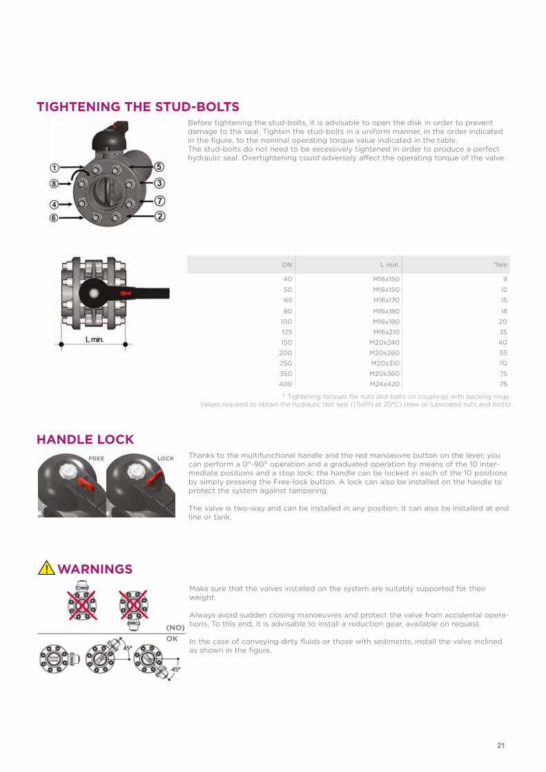
TIGHTENING THE STUD-BOLTSBefore tightening the stud-bolts, it is advisable to open the disk in order to prevent damage to the seal. Tighten the stud-bolts in a uniform manner, in the order indicated in the figure, to the nominal operating torque value indicated in the table. The stud-bolts do not need to be excessively tightened in order to produce a perfect hydraulic seal. Overtightening could adversely affect the operating torque of the valve.
* Tightening torques for nuts and bolts on couplings with backing rings.Values required to obtain the hydraulic test seal (1.5xPN at 20°C) (new or lubricated nuts and bolts)
DN L min. *Nm
40 M16x150 9
50 M16x150 12
65 M16x170 15
80 M16x180 18
100 M16x180 20
125 M16x210 35
150 M20x240 40
200 M20x260 55
250 M20x310 70
350 M20x360 75
400 M24x420 75
HANDLE LOCKThanks to the multifunctional handle and the red manoeuvre button on the lever, you can perform a 0°-90° operation and a graduated operation by means of the 10 inter-mediate positions and a stop lock: the handle can be locked in each of the 10 positions by simply pressing the Free-lock button. A lock can also be installed on the handle to protect the system against tampering.
The valve is two-way and can be installed in any position. It can also be installed at end line or tank.
FREE LOCK
WARNINGSMake sure that the valves installed on the system are suitably supported for their weight.
Always avoid sudden closing manoeuvres and protect the valve from accidental opera-tions. To this end, it is advisable to install a reduction gear, available on request.
In the case of conveying dirty fluids or those with sediments, install the valve inclined as shown in the figure.
(NO)OK
21

McSYS, IncAdd: 2211 Jungwang-Dong,Siheung-Si,Kyunggi-Do,KoreaTel: +82-31-319-6560Fax: +82-31-8041-3410Email: [email protected]
www.j-mcsys.comwww.j-mcsys.net


![FIP manuaaliset venttiillit esite [Yhteensopivuustila] · Self Customization Thanks to the dedicated Easyfit Labelling System it is possible to create custom label Easyfit Labelling](https://img.pdfslide.net/doc/110x75/5ae1a8037f8b9a0d7d8b6f0f/fip-manuaaliset-venttiillit-esite-yhteensopivuustila-customization-thanks-to-the.jpg)