Embed Size (px)
Citation preview
ORIGINAL ARTICLE
Machinability and manufacturing cost in low-lead brass
Fredrik Schultheiss1 & Christina Windmark1 & Stefan Sjöstrand1& Magnus Rasmusson1
& Jan-Eric Ståhl1
Received: 6 March 2017 /Accepted: 12 March 2018# The Author(s) 2018
AbstractToday, commercially used brasses commonly contain 2 to 4 wt% lead. As the availability of low-lead and lead-free brassincreases, there are environmental incentives for investigating the consequences of replacing the lead-containing brasses withlead-free equivalents. Generally, lead-free brass is expected to have a lower machinability than its lead-alloyed counterpart,implying a higher manufacturing cost. Thus, the aim of this study has been to quantify the added manufacturing cost by replacinga standard brass alloy with a low-lead alternative. This was done through a case study performed at a Swedish SME whichreplaced CuZn39Pb3 (3.3 wt% Pb) with low-lead CuZn21Si3P (< 0.09 wt% lead) for a select part. Since CuZn21Si3P is almosttwice as expensive as CuZn39Pb3, the material cost was found to have a substantial influence on the manufacturing cost.Additionally, the lower machinability implied a longer cycle time and higher losses while machining CuZn21Si3P, resulting ina 77% overall increase inmanufacturing cost when using the low-leadmaterial. Arguably, the difference inmaterial cost, and thusmanufacturing cost, may decrease over time making production of low-lead and lead-free brass products a viable option,especially when considering the environmental incentive for decreasing the amount of lead in circulation.
Keywords Machining . Brass . Lead .Machinability .Manufacturing cost
1 Introduction
Lead is a common additive in free-machining brasses.According to European legislation, copper alloys, e.g., brass,are currently allowed to contain up to 4 wt% lead [1]. Theaddition of lead in brass is considered as improving the ma-chinability through improving chip breaking, lowering cuttingforces, decreasing tool wear, and permitting better surfaceroughness and tolerances [2]. However, as the importance ofsustainable production is increasingly recognized, interest fordecreasing the amount of lead in circulation is growing.Further legislative actions, decreasing the amount of lead inbrass, are likely in the future as emphasized by Nobel et al. [3]even if none has thus far been published.
Lead (Pb) is a heavy metal which is toxic even at lowexposure levels and has been found to have acute and chroniceffects on human health. In nature, lead is toxic to plants,
animals, and microorganisms [4]. The International Leadand Zinc Study Group, formed by the United Nations 1959,has estimated that 115,000 t of lead was used in differentalloys during 2003 by the countries reporting to the organiza-tion, estimated as being equivalent to roughly 80% of theworld consumption during the same time period [4]. Lead issoluble in molten brass but precipitates into the grain bound-aries during solidification commonly forming particles 1 to10 μm in diameter [5]. Trent and Wright [5] found that addi-tion of lead in brass greatly reduces the cutting forces, shortensthe chips, and decreases the tool wear.
Due to the detrimental effects of lead on the environment,several alternative alloying elements have been proposed. Forexample, La Fontaine and Keast [6] evaluated the possibilityof substituting lead with bismuth in brass with promising re-sults. Later, Li et al. [7] proposed the addition of a smallamount of titanium in the bismuth-alloyed brass. However,the high price of bismuth and titanium compared to otheralloying elements has discouraged any further use. Anotherpossible solution is to substitute lead with silicon although thishas been perceived as somewhat reducing the machinability assummarized by Taha et al. [8], thus conceivably increasing themanufacturing cost.
To assess the impact of changing workpiece material, i.e.,machinability, manufacturing cost may well be a crucial
* Fredrik [email protected]
1 Production and Materials Engineering, Lund University, 22100 Lund, Sweden
https://doi.org/10.1007/s00170-018-1866-4The International Journal of Advanced Manufacturing Technology (2018) 99:2101–2110
/Published online: 20 March 2018
parameter to compare. This is because costs often are the basisfor informed decisions concerning the production system andbecause there are manufacturing cost models incorporatingperformance, enabling an overall analysis on the effects ofchanging the process prerequisites. Hence,manufacturing costcan be used comparing different developmental scenarios,such as substitution of workpiece material. Previous researchby the authors have proven that it is possible to machine partsin brasses with varying lead content, although proper consid-erations are required while selecting the process conditions[9]. Since the manufacturing process must be adapted for thedifferent workpiece materials, i.e., lead-containing, low-lead,and lead-free brass, this will imply a variation of themanufacturing cost. It is also plausible to assume that thisvariation of workpiece materials will influence the loss param-eters during machining, i.e., scrap rate, downtime rate, andproduction rate loss. Thus, the aim of the study described inthis paper has been to investigate the monetary effect oftransitioning to low-lead brass from a production perspective.This knowledge can then be weighed against the envisionedenvironmental benefits, possibly encouraging an increaseduse of environmental friendly materials, and thus contributingto sustainable production.
2 Manufacturing cost calculation
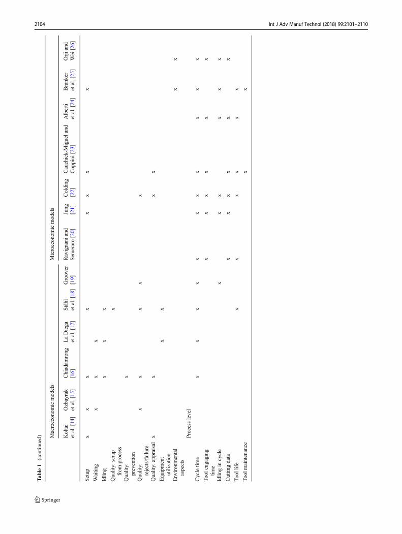
Several different models for calculating the manufacturingcost have been published through the years. Summaries andreviews have for example been published by [10–13].Based on the cost models review done by Jönsson [13]and later extended by Ståhl [12], an overview of costmodels available for assessing manufacturing has beencompiled (Table 1). As stated by Tipnis et al. [24], thesemodels can usually be divided into microeconomic modelsand macroeconomic models. Typically, microeconomicmodels specify the influence of specific process parameterson the manufacturing cost. In the bottom right corner ofTable 1, models related to microeconomic considerationscan be seen to have a considerably higher number of pa-rameters connected to the process level. Such models formachining operations have for instance been published byColding [22] and Alberti et al. [24] among others. For ex-ample, these models can describe how the cutting data, i.e.,cutting speed, feed, and depth of cut, influences themanufacturing cost. In contrast, in a macroeconomic mod-el, several of these process parameters have been aggregat-ed in order to form a more holistic model. A typical exam-ple of this could be to only base macroeconomic models oncycle time and not the individual factors influencing thecycle time. Groover [19] has published a macroeconomicmodel that only takes one production loss parameter intoconsideration, the scrap rate. Ravignani and Semeraro [20]
have developed a model which combines micro- and mac-roeconomic factors by including both cutting conditionsand the batch size. However, their model does not takeany loss parameters into consideration. Overall, microeco-nomic models are specific for the manufacturing process inquestion, requiring numerous different models dependingon circumstances. In comparison, a macroeconomic modelmay be used for different manufacturing process, althoughit inhibits evaluation of how specific process conditionsinfluence the manufacturing cost. This problem is partlyovercome by using the manufacturing cost model intro-duced by Ståhl et al. [18], and later improved by Jönssonet al. [27]. Their model, Eq. (1), can be described as amacroeconomic model with the added benefit of consider-ing selected microeconomic parameters. The selected mi-croeconomic parameters are performance parameters on asystem level instead of the process level, see Table 1, givingthe speed rate based on ideal cycle time, the downtime rate,and quality rate of a produced product. The economic qual-ity cost model published by Chiadamrong [16] also incor-porate microeconomic parameters into a macroeconomicmodel, e.g., quality, idling, and downtime in equipment,but does not take speed rate losses into consideration. Themodel is extensive and include vital aspect of production,compared with the model presented by Ståhl et al. [18]. Thecomplexity of the model is vastly surpassed, which impedesthe usability.
k ¼ kAN 0
þ kBN 0
N 0
1−qQ
" #þ kCP
60N0
t0∙N0
1−qQ� �
1−qPð Þ
24
35þ
kCS60N 0
t0∙N 0
1−qQ� �
1−qPð Þ∙qS
1−qSþ Tsu þ 1−URP
URPTPb
24
35þ
kD60N 0
t0∙N 0
1−qQ� �
1−qPð Þ∙ 1þ qS
1−qS
� �þ Tsu þ 1−URP
URPTPb
24
35
ð1Þ
The following denotations are used in Eq. (1): part cost k,tool cost kA, material cost kB, machine cost during productionkCP, machine cost during downtime kCS, personnel cost kD,nominal batch size N0, nominal cycle time t0, scrap rate qQ,downtime rate qS, production rate qP, setup time Tsu, machineutilization URP, and production time of a batch TPb.
3 Machinability of brass
Brass, a copper-zinc alloy, is a common engineering mate-rial used for an array of different products. Many so-calledfree-machining brasses contain up to 4 wt% lead, although
2102 Int J Adv Manuf Technol (2018) 99:2101–2110
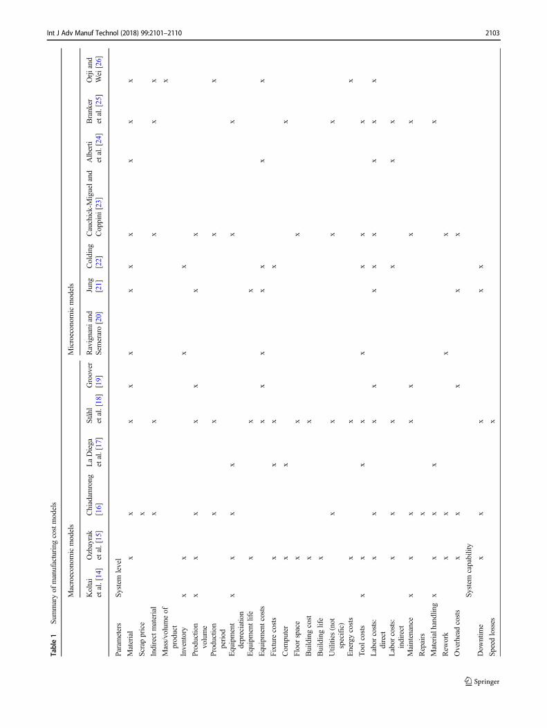
Table1
Summaryof
manufacturing
costmodels
Macroeconom
icmodels
Microeconom
icmodels
Koltai
etal.[14]
Ozbayrak
etal.[15]
Chiadam
rong
[16]
LaDiega
etal.[17]
Ståhl
etal.[18]
Groover
[19]
Ravignani
and
Semeraro[20]
Jung
[21]
Colding
[22]
Cauchick-Migueland
Coppini
[23]
Alberti
etal.[24]
Branker
etal.[25]
Orjiand
Wei[26]
Param
eters
System
level
Material
xx
xx
xx
xx
xx
x
Scrapprice
x
Indirectmaterial
xx
xx
x
Mass/volumeof
product
x
Inventory
xx
xx
Productio
nvolume
xx
xx
xx
x
Productio
nperiod
xx
xx
Equipment
depreciatio
nx
xx
xx
x
Equipmentlife
xx
x
Equipmentcosts
xx
xx
xx
x
Fixture
costs
xx
xx
Com
puter
xx
x
Floorspace
xx
x
Buildingcost
xx
Buildinglife
x
Utilities
(not
specific)
xx
xx
Energycosts
xx
x
Tool
costs
xx
xx
xx
xx
Labor
costs:
direct
xx
xx
xx
xx
xx
Labor
costs:
indirect
xx
xx
xx
Maintenance
xx
xx
xx
x
Repairs
x
Materialhandling
xx
xx
x
Rew
ork
xx
xx
Overheadcosts
xx
xx
x
System
capability
Dow
ntim
ex
xx
xx
Speed
losses
x
2103Int J Adv Manuf Technol (2018) 99:2101–2110
Tab
le1
(contin
ued) M
acroeconom
icmodels
Microeconom
icmodels
Koltai
etal.[14]
Ozbayrak
etal.[15]
Chiadam
rong
[16]
LaDiega
etal.[17]
Ståhl
etal.[18]
Groover
[19]
Ravignani
and
Semeraro[20]
Jung
[21]
Colding
[22]
Cauchick-Migueland
Coppini
[23]
Alberti
etal.[24]
Branker
etal.[25]
Orjiand
Wei[26]
Setup
xx
xx
xx
xx
Waitin
gx
xx
Idlin
gx
xx
Quality:
scrap
from
process
x
Quality:
preventio
nx
Quality:
rejects/failu
rex
xx
xx
Quality:appraisalx
xx
x
Equipment
utilizatio
nx
x
Environmental
aspects
xx
Processlevel
Cycletim
ex
xx
xx
xx
xx
xx
Tool
engaging
time
xx
xx
xx
Idlin
gin
cycle
xx
xx
xx
Cuttin
gdata
xx
xx
xx
Tool
life
xx
xx
xx
Toolmaintenance
xx
2104 Int J Adv Manuf Technol (2018) 99:2101–2110
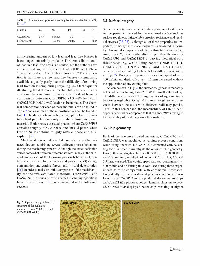
an increasing amount of low-lead and lead-free brasses isbecoming commercially available. The permissible amountof lead in a lead-free brass is disputed, but the authors havechosen to designate levels of lead < 0.05 wt% Pb as“lead-free” and < 0.2 wt% Pb as “low-lead.” The implica-tion is that there are few lead-free brasses commerciallyavailable, arguably partly due to the difficulty of removinglead from brass scrap during recycling. As a technique forillustrating the difference in machinability between a con-ventional free-machining brass and a low-lead brass, acomparison between CuZn39Pb3 (3.3 wt% lead) andCuZn21Si3P (< 0.09 wt% lead) has been made. The chem-ical composition for each of these materials can be found inTable 2 and examples of the microstructures can be found inFig. 1. The dark spots in each micrograph in Fig. 1 consti-tutes lead particles randomly distribute throughout eachmaterial. Both brasses are dual-phased where CuZn39Pb3contains roughly 70% α-phase and 30% β-phase whileCuZn21Si3P contains roughly 60% α-phase and 40%κ-phase [30].
Machinability is a multi-faceted parameter generally eval-uated through combining several different process behaviorsduring the machining process. Although the exact definitionvaries somewhat between different sources, many authors in-clude most or all of the following process behaviors: (1) sur-face integrity, (2) chip geometry and properties, (3) energyconsumption and cutting forces, and (4) tool deterioration[31]. In order to make an initial comparison of the machinabil-ity for the two evaluated materials, CuZn39Pb3 andCuZn21Si3P, a series of experimental machining operationshave been performed [9], as summarized in the followingsections.
3.1 Surface integrity
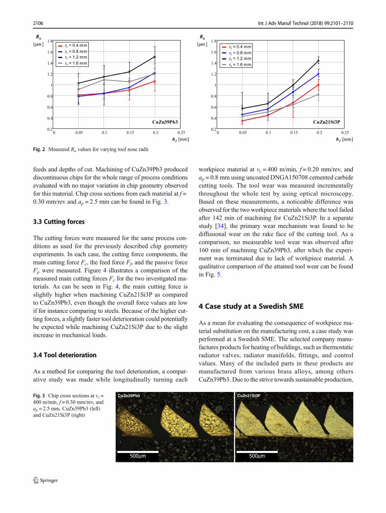
Surface integrity has a wide definition pertaining to all mate-rial properties influenced by the machined surface such assurface roughness, fatigue life, corrosion resistance, and resid-ual stresses [32, 33]. Although all of these properties are im-portant, primarily the surface roughness is measured in indus-try. An initial comparison of the arithmetic mean surfaceroughness Ra was made after longitudinally turningCuZn39Pb3 and CuZn21Si3P at varying theoretical chipthicknesses, h1, while using coated CNMG120404,CNMG120408, CNMG120412, and CNMG120416cemented carbide cutting tools with four different nose radii,rε (Fig. 2). During all experiments, a cutting speed of vc =400 m/min and depth of cut ap = 1.5 mm were used withoutthe application of any cutting fluid.
As can be seen in Fig. 2, the surface roughness is markedlybetter while machining CuZn21Si3P for small values of h1.The difference decreases for large values of h1, essentiallybecoming negligible for h1 = 0.2 mm although some differ-ences between the tools with different radii may persist.Thus, in this comparison, the machinability of CuZn21Si3Pappears better when compared to that of CuZn39Pb3 owing tothe possibility of producing smoother surfaces.
3.2 Chip geometry
Each of the two investigated materials, CuZn39Pb3 andCuZn21Si3P, was machined at varying process conditionswhile using uncoated DNGA150708 cemented carbide cut-ting tools in order to investigate the obtained chip geometry.During this investigation feed, f = 0.05, 0.10, 0.15, 0.20, 0.25,and 0.30 mm/rev, and depth of cut, ap = 0.5, 1.0, 1.5, 2.0, and2.5 mm, was used. The cutting speed was kept constant at vc =400 m/min and no cutting fluid was used during these exper-iments as to be comparable with commercial processes.Consistently for the investigated process conditions, it wasfound that CuZn39Pb3 mostly produced discontinuous chipsand CuZn21Si3P produced longer, lamellar chips. As expect-ed, CuZn21Si3P displayed better chip breaking at higher
CuZn39Pb3 CuZn21Si3PFig. 1 Optical micrograph on thestructure of the evaluatedmaterials. CuZn39Pb3 (left) andCuZn21Si3P (right)
Table 2 Chemical composition according to nominal standards (wt%)[28, 29]
Material Cu Zn Pb Si P
CuZn39Pb3 57.3 Balance 3.3 – –
CuZn21Si3P 76 Balance < 0.09 3 0.05
2105Int J Adv Manuf Technol (2018) 99:2101–2110
feeds and depths of cut. Machining of CuZn39Pb3 produceddiscontinuous chips for the whole range of process conditionsevaluated with no major variation in chip geometry observedfor this material. Chip cross sections from each material at f =0.30 mm/rev and ap = 2.5 mm can be found in Fig. 3.
3.3 Cutting forces
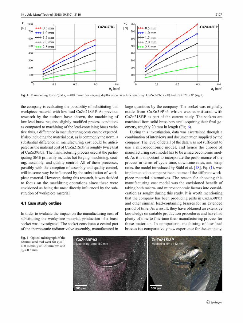
The cutting forces were measured for the same process con-ditions as used for the previously described chip geometryexperiments. In each case, the cutting force components, themain cutting force Fc, the feed force Ff, and the passive forceFp were measured. Figure 4 illustrates a comparison of themeasured main cutting forces Fc for the two investigated ma-terials. As can be seen in Fig. 4, the main cutting force isslightly higher when machining CuZn21Si3P as comparedto CuZn39Pb3, even though the overall force values are lowif for instance comparing to steels. Because of the higher cut-ting forces, a slightly faster tool deterioration could potentiallybe expected while machining CuZn21Si3P due to the slightincrease in mechanical loads.
3.4 Tool deterioration
As a method for comparing the tool deterioration, a compar-ative study was made while longitudinally turning each
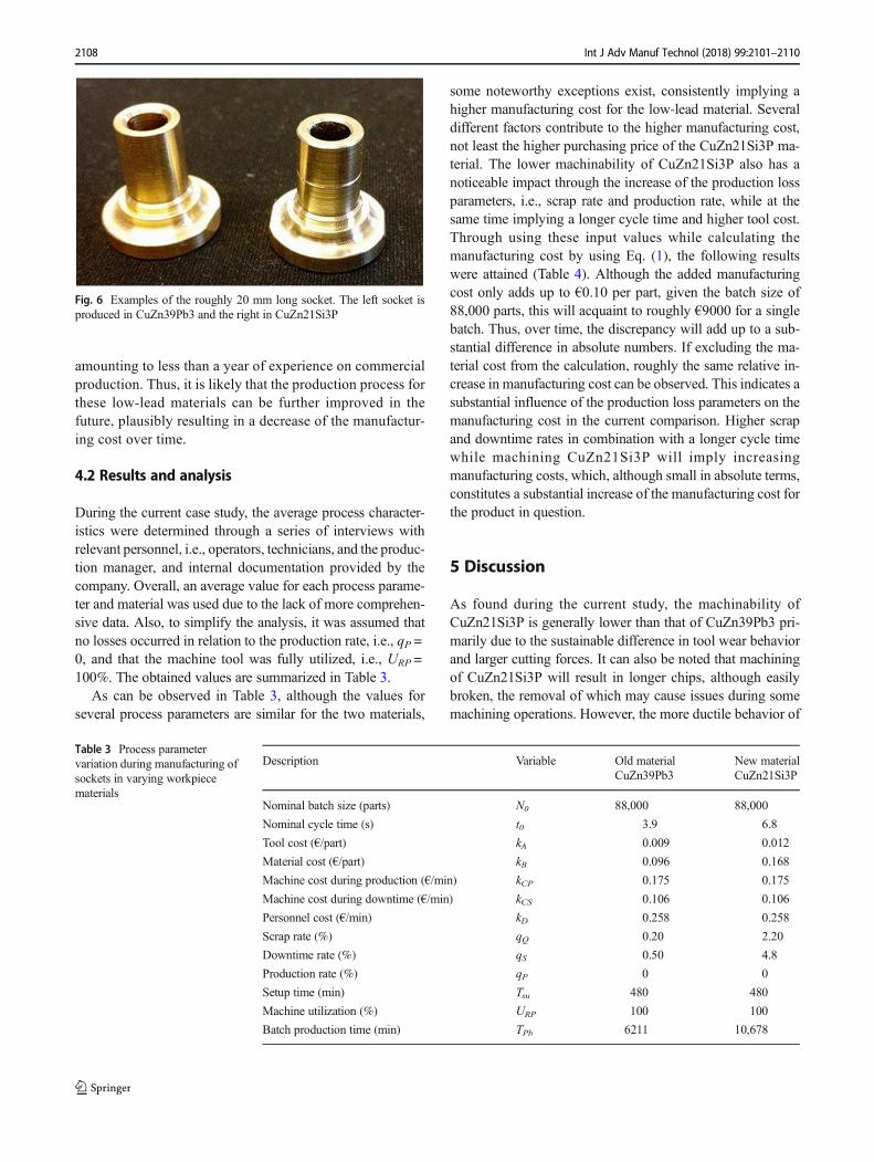
workpiece material at vc = 400 m/min, f = 0.20 mm/rev, andap = 0.8 mm using uncoated DNGA150708 cemented carbidecutting tools. The tool wear was measured incrementallythroughout the whole test by using optical microscopy.Based on these measurements, a noticeable difference wasobserved for the two workpiece materials where the tool failedafter 142 min of machining for CuZn21Si3P. In a separatestudy [34], the primary wear mechanism was found to bediffusional wear on the rake face of the cutting tool. As acomparison, no measurable tool wear was observed after160 min of machining CuZn39Pb3, after which the experi-ment was terminated due to lack of workpiece material. Aqualitative comparison of the attained tool wear can be foundin Fig. 5.
4 Case study at a Swedish SME
As a mean for evaluating the consequence of workpiece ma-terial substitution on the manufacturing cost, a case study wasperformed at a Swedish SME. The selected company manu-factures products for heating of buildings, such as thermostaticradiator valves, radiator manifolds, fittings, and controlvalues. Many of the included parts in these products aremanufactured from various brass alloys, among othersCuZn39Pb3. Due to the strive towards sustainable production,
0 0.05 0.1 0.15 0.2 0.250.2
0.4
0.6
0.8
1
1.2
1.4
1.6
1.8Ra
[µm ]
CuZn21Si3P
h1 [mm]
0 0.05 0.1 0.15 0.2 0.250.2
0.4
0.6
0.8
1
1.2
1.4
1.6
1.8Ra
[µm ]
CuZn39Pb3
h1 [mm]
rε = 0.4 mmrε = 0.8 mmrε = 1.2 mmrε = 1.6 mm
rε = 0.4 mmrε = 0.8 mmrε = 1.2 mmrε = 1.6 mm
Fig. 2 Measured Ra values for varying tool nose radii
CuZn39Pb3 CuZn21Si3PFig. 3 Chip cross sections at vc =400 m/min, f = 0.30 mm/rev, andap = 2.5 mm. CuZn39Pb3 (left)and CuZn21Si3P (right)
2106 Int J Adv Manuf Technol (2018) 99:2101–2110
the company is evaluating the possibility of substituting thisworkpiece material with low-lead CuZn21Si3P. As previousresearch by the authors have shown, the machining oflow-lead brass requires slightly modified process conditionsas compared to machining of the lead-containing brass varie-ties; thus, a difference in manufacturing costs can be expected.If also including the material cost, as is commonly the norm, asubstantial difference in manufacturing cost could be antici-pated as the material cost of CuZn21Si3P is roughly twice thatof CuZn39Pb3. The manufacturing process used at the partic-ipating SME primarily includes hot forging, machining, coat-ing, assembly, and quality control. All of these processes,possibly with the exception of assembly and quality control,will in some way be influenced by the substitution of work-piece material. However, during this research, it was decidedto focus on the machining operations since these wereenvisioned as being the most directly influenced by the sub-stitution of workpiece material.
4.1 Case study outline
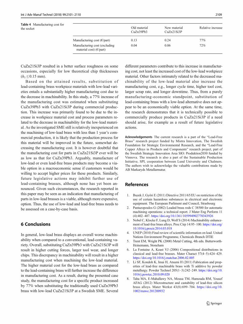
In order to evaluate the impact on the manufacturing cost ofsubstituting the workpiece material, production of a brasssocket was investigated. The socket constitutes a central partof the thermostatic radiator valve assembly, manufactured in
large quantities by the company. The socket was originallymade from CuZn39Pb3 which was substituted withCuZn21Si3P as part of the current study. The sockets aremachined from solid brass bars until acquiring their final ge-ometry, roughly 20 mm in length (Fig. 6).
During this investigation, data was ascertained through acombination of interviews and documentation supplied by thecompany. The level of detail of the data was not sufficient touse a microeconomic model, and hence the choice ofmanufacturing cost model has to be a macroeconomic mod-el. As it is important to incorporate the performance of theprocess in terms of cycle time, downtime rates, and scraprates, the model introduced by Ståhl et al. [18], Eq. (1), wasimplemented to compare the outcome of the different work-piece material alternatives. The reason for choosing thismanufacturing cost model was the envisioned benefit oftaking both macro- and microeconomic factors into consid-eration as sought during this study. It is worth mentioningthat the company has been producing parts in CuZn39Pb3and other similar, lead-containing brasses for an extendedperiod of time. As a result, they have obtained an extensiveknowledge on suitable production procedures and have hadplenty of time to fine-tune their manufacturing process forthese materials. In comparison, machining of low-leadbrasses is a comparatively new experience for the company,
0 0.1 0.2 0.3 0.40
100
200
300
400
500
600
700
800
0.5 mm
1.0 mm
1.5 mm
2.0 mm
2.5 mm
Fc[N] CuZn39Pb3
h1 [mm]
0 0.1 0.2 0.3 0.40
100
200
300
400
500
600
700
800
0.5 mm
1.0 mm
1.5 mm
2.0 mm
2.5 mm
Fc[N] CuZn21Si3P
h1 [mm]
Fig. 4 Main cutting force Fc at vc = 400 m/min for varying depths of cut as a function of h1. CuZn39Pb3 (left) and CuZn21Si3P (right)
500 µm 500 µm
CuZn39Pb3Machining time 160 min
CuZn21Si3PMachining time 142 min
Fig. 5 Optical micrograph of theaccumulated tool wear for vc =400 m/min, f = 0.20 mm/rev, andap = 0.8 mm
2107Int J Adv Manuf Technol (2018) 99:2101–2110
amounting to less than a year of experience on commercialproduction. Thus, it is likely that the production process forthese low-lead materials can be further improved in thefuture, plausibly resulting in a decrease of the manufactur-ing cost over time.
4.2 Results and analysis
During the current case study, the average process character-istics were determined through a series of interviews withrelevant personnel, i.e., operators, technicians, and the produc-tion manager, and internal documentation provided by thecompany. Overall, an average value for each process parame-ter and material was used due to the lack of more comprehen-sive data. Also, to simplify the analysis, it was assumed thatno losses occurred in relation to the production rate, i.e., qP =0, and that the machine tool was fully utilized, i.e., URP =100%. The obtained values are summarized in Table 3.
As can be observed in Table 3, although the values forseveral process parameters are similar for the two materials,
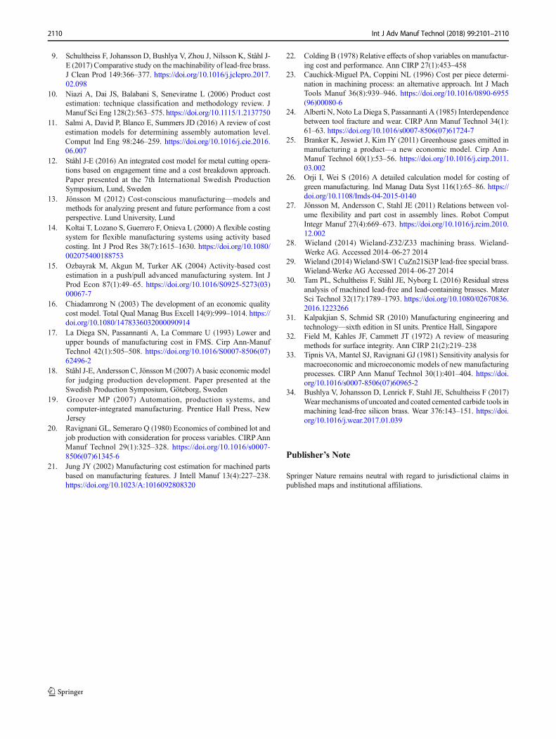
some noteworthy exceptions exist, consistently implying ahigher manufacturing cost for the low-lead material. Severaldifferent factors contribute to the higher manufacturing cost,not least the higher purchasing price of the CuZn21Si3P ma-terial. The lower machinability of CuZn21Si3P also has anoticeable impact through the increase of the production lossparameters, i.e., scrap rate and production rate, while at thesame time implying a longer cycle time and higher tool cost.Through using these input values while calculating themanufacturing cost by using Eq. (1), the following resultswere attained (Table 4). Although the added manufacturingcost only adds up to €0.10 per part, given the batch size of88,000 parts, this will acquaint to roughly €9000 for a singlebatch. Thus, over time, the discrepancy will add up to a sub-stantial difference in absolute numbers. If excluding the ma-terial cost from the calculation, roughly the same relative in-crease in manufacturing cost can be observed. This indicates asubstantial influence of the production loss parameters on themanufacturing cost in the current comparison. Higher scrapand downtime rates in combination with a longer cycle timewhile machining CuZn21Si3P will imply increasingmanufacturing costs, which, although small in absolute terms,constitutes a substantial increase of the manufacturing cost forthe product in question.
5 Discussion
As found during the current study, the machinability ofCuZn21Si3P is generally lower than that of CuZn39Pb3 pri-marily due to the sustainable difference in tool wear behaviorand larger cutting forces. It can also be noted that machiningof CuZn21Si3P will result in longer chips, although easilybroken, the removal of which may cause issues during somemachining operations. However, the more ductile behavior of
Table 3 Process parametervariation during manufacturing ofsockets in varying workpiecematerials
Description Variable Old materialCuZn39Pb3
New materialCuZn21Si3P
Nominal batch size (parts) N0 88,000 88,000
Nominal cycle time (s) t0 3.9 6.8
Tool cost (€/part) kA 0.009 0.012
Material cost (€/part) kB 0.096 0.168
Machine cost during production (€/min) kCP 0.175 0.175
Machine cost during downtime (€/min) kCS 0.106 0.106
Personnel cost (€/min) kD 0.258 0.258
Scrap rate (%) qQ 0.20 2.20
Downtime rate (%) qS 0.50 4.8
Production rate (%) qP 0 0
Setup time (min) Tsu 480 480
Machine utilization (%) URP 100 100
Batch production time (min) TPb 6211 10,678
Fig. 6 Examples of the roughly 20 mm long socket. The left socket isproduced in CuZn39Pb3 and the right in CuZn21Si3P
2108 Int J Adv Manuf Technol (2018) 99:2101–2110
CuZn21Si3P resulted in a better surface roughness on someoccasions, especially for low theoretical chip thicknesses(h1 ≤ 0.15 mm).
Based on the at ta ined resul ts , subst i tu t ion oflead-containing brass workpiece materials with low-lead vari-eties entails a substantially higher manufacturing cost due tothe decrease in machinability. In this study, a 77% increase ofthe manufacturing cost was estimated when substitutingCuZn39Pb3 with CuZn21Si3P during commercial produc-tion. This increase was primarily found to be due to the in-crease in workpiece material cost and process parameters re-lated to the decrease in machinability for the low-lead materi-al. As the investigated SME still is relatively inexperienced onthe machining of low-lead brass with less than 1 year’s com-mercial production, it is likely that the production process forthis material will be improved in the future, somewhat de-creasing the manufacturing cost. It is however doubtful thatthe manufacturing cost for parts in CuZn21Si3P ever will beas low as that for CuZn39Pb3. Arguably, manufacture oflow-lead or even lead-free brass products may become a via-ble option in a macroeconomic sense if customers would bewilling to accept higher prices for these products. Similarly,future legislative actions may inhibit further use oflead-containing brasses, although none has yet been an-nounced. Given such circumstances, the research reported inthis paper may be seen as an indication that manufacturing ofparts in low-lead brasses is a viable, althoughmore expensive,option. Thus, the use of low-lead and lead-free brass needs tobe assessed on a case-by-case basis.
6 Conclusions
In general, low-lead brass displays an overall worse machin-ability when compared to a conventional, lead-containing va-riety. Overall, substituting CuZn39Pb3 with CuZn21Si3P willresult in higher cutting forces, larger tool wear, and longerchips. This discrepancy in machinability will result in a highermanufacturing cost when machining the low-lead material.The higher material cost for the low-lead brass as comparedto the lead-containing brass will further increase the differencein manufacturing cost. As a result, during the presented casestudy, the manufacturing cost for a specific product increasedby 77% when substituting the traditionally used CuZn39Pb3brass with low-lead CuZn21Si3P at a Swedish SME. Several
different parameters contribute to this increase in manufactur-ing cost, not least the increased cost of the low-lead workpiecematerial. Other factors intimately related to the decreased ma-chinability of the low-lead material also increase themanufacturing cost, e.g., longer cycle time, higher tool cost,larger scrap rate, and longer downtime. Thus, from a purelymanufacturing-economic standpoint, substitution oflead-containing brass with a low-lead alternative does not ap-pear to be an economically viable option. At the same time,the research demonstrates that it is technically possible tocommercially produce products in CuZn21Si3P if a needshould arise, for example as a result of future legislativeactions.
Acknowledgements The current research is a part of the “Lead-FreeBrass” research project funded by Mistra Innovation, The SwedishFoundation for Strategic Environmental Research, and the “Lead-FreeCopper Alloys in Products and Components” research project, part ofthe Swedish Strategic Innovation Area SIO: Produktion2030 funded byVinnova. The research is also a part of the Sustainable ProductionInitiative, SPI, cooperation between Lund University and Chalmers.The authors wish to acknowledge the valuable contributions made byAB Markaryds Metallarmatur.
References
1. Buzek J, Győri E (2011) Directive 2011/65/EU on restriction of theuse of certain hazardous substances in electrical and electronicequipment. The European Parliment and Council, Strasbourg
2. Pantazopoulos G (2002) Leaded brass rods C 38500 for automaticmachining operations: a technical report. J Mater Eng Perform 11(4):402–407. https://doi.org/10.1361/105994902770343926
3. Nobel C, Klocke F, Lung D,Wolf S (2014) Machinability enhance-ment of lead-free brass alloys. Proc Cirp 14:95–100. https://doi.org/10.1016/j.procir.2014.03.018
4. UNEP (2010) Final review of scientific information on lead. UnitedNations Environment Programme, Chemicals Branch DTIE
5. Trent EM, Wright PK (2000) Metal Cutting, 4th edn. Butterworth-Heinemann, Stoneham
6. La Fontaine A, Keast VJ (2006) Compositional distributions inclassical and lead-free brasses. Mater Charact 57(4–5):424–429.https://doi.org/10.1016/j.matchar.2006.02.005
7. Li SF, Kondoh K, Imai H, Atsumi H (2011) Fabrication and prop-erties of lead-free machinable brass with Ti additive by powdermetallurgy. Powder Technol 205(1–3):242–249. https://doi.org/10.1016/j.powtec.2010.09.020
8. Taha MA, E-Mahallawy NA, Mousa TM, Hamouda RM, YousefAFAG (2012) Microstructure and castability of lead-free siliconbrass alloys. Mater Werkst 43(8):699–704. https://doi.org/10.1002/mawe.201200932
Table 4 Manufacturing cost forthe socket Old material
CuZn39Pb3New materialCuZn21Si3P
Relative increase
Manufacturing cost (€/part) 0.13 0.24 77%
Manufacturing cost (excludingmaterial cost) (€/part)
0.04 0.06 72%
2109Int J Adv Manuf Technol (2018) 99:2101–2110
9. Schultheiss F, Johansson D, Bushlya V, Zhou J, Nilsson K, Ståhl J-E (2017) Comparative study on themachinability of lead-free brass.J Clean Prod 149:366–377. https://doi.org/10.1016/j.jclepro.2017.02.098
10. Niazi A, Dai JS, Balabani S, Seneviratne L (2006) Product costestimation: technique classification and methodology review. JManuf Sci Eng 128(2):563–575. https://doi.org/10.1115/1.2137750
11. Salmi A, David P, Blanco E, Summers JD (2016) A review of costestimation models for determining assembly automation level.Comput Ind Eng 98:246–259. https://doi.org/10.1016/j.cie.2016.06.007
12. Ståhl J-E (2016) An integrated cost model for metal cutting opera-tions based on engagement time and a cost breakdown approach.Paper presented at the 7th International Swedish ProductionSymposium, Lund, Sweden
13. Jönsson M (2012) Cost-conscious manufacturing—models andmethods for analyzing present and future performance from a costperspective. Lund University, Lund
14. Koltai T, Lozano S, Guerrero F, Onieva L (2000) A flexible costingsystem for flexible manufacturing systems using activity basedcosting. Int J Prod Res 38(7):1615–1630. https://doi.org/10.1080/002075400188753
15. Ozbayrak M, Akgun M, Turker AK (2004) Activity-based costestimation in a push/pull advanced manufacturing system. Int JProd Econ 87(1):49–65. https://doi.org/10.1016/S0925-5273(03)00067-7
16. Chiadamrong N (2003) The development of an economic qualitycost model. Total Qual Manag Bus Excell 14(9):999–1014. https://doi.org/10.1080/1478336032000090914
17. La Diega SN, Passannanti A, La Commare U (1993) Lower andupper bounds of manufacturing cost in FMS. Cirp Ann-ManufTechnol 42(1):505–508. https://doi.org/10.1016/S0007-8506(07)62496-2
18. Ståhl J-E, Andersson C, JönssonM (2007) A basic economicmodelfor judging production development. Paper presented at theSwedish Production Symposium, Göteborg, Sweden
19. Groover MP (2007) Automation, production systems, andcomputer-integrated manufacturing. Prentice Hall Press, NewJersey
20. Ravignani GL, Semeraro Q (1980) Economics of combined lot andjob production with consideration for process variables. CIRPAnnManuf Technol 29(1):325–328. https://doi.org/10.1016/s0007-8506(07)61345-6
21. Jung JY (2002) Manufacturing cost estimation for machined partsbased on manufacturing features. J Intell Manuf 13(4):227–238.https://doi.org/10.1023/A:1016092808320
22. Colding B (1978) Relative effects of shop variables on manufactur-ing cost and performance. Ann CIRP 27(1):453–458
23. Cauchick-Miguel PA, Coppini NL (1996) Cost per piece determi-nation in machining process: an alternative approach. Int J MachTools Manuf 36(8):939–946. https://doi.org/10.1016/0890-6955(96)00080-6
24. Alberti N, Noto La Diega S, Passannanti A (1985) Interdependencebetween tool fracture and wear. CIRP Ann Manuf Technol 34(1):61–63. https://doi.org/10.1016/s0007-8506(07)61724-7
25. Branker K, Jeswiet J, Kim IY (2011) Greenhouse gases emitted inmanufacturing a product—a new economic model. Cirp Ann-Manuf Technol 60(1):53–56. https://doi.org/10.1016/j.cirp.2011.03.002
26. Orji I, Wei S (2016) A detailed calculation model for costing ofgreen manufacturing. Ind Manag Data Syst 116(1):65–86. https://doi.org/10.1108/Imds-04-2015-0140
27. Jönsson M, Andersson C, Stahl JE (2011) Relations between vol-ume flexibility and part cost in assembly lines. Robot ComputIntegr Manuf 27(4):669–673. https://doi.org/10.1016/j.rcim.2010.12.002
28. Wieland (2014) Wieland-Z32/Z33 machining brass. Wieland-Werke AG. Accessed 2014–06-27 2014
29. Wieland (2014)Wieland-SW1 CuZn21Si3P lead-free special brass.Wieland-Werke AG Accessed 2014–06-27 2014
30. Tam PL, Schultheiss F, Ståhl JE, Nyborg L (2016) Residual stressanalysis of machined lead-free and lead-containing brasses. MaterSci Technol 32(17):1789–1793. https://doi.org/10.1080/02670836.2016.1223266
31. Kalpakjian S, Schmid SR (2010) Manufacturing engineering andtechnology—sixth edition in SI units. Prentice Hall, Singapore
32. Field M, Kahles JF, Cammett JT (1972) A review of measuringmethods for surface integrity. Ann CIRP 21(2):219–238
33. Tipnis VA, Mantel SJ, Ravignani GJ (1981) Sensitivity analysis formacroeconomic and microeconomic models of new manufacturingprocesses. CIRP Ann Manuf Technol 30(1):401–404. https://doi.org/10.1016/s0007-8506(07)60965-2
34. Bushlya V, Johansson D, Lenrick F, Stahl JE, Schultheiss F (2017)Wearmechanisms of uncoated and coated cemented carbide tools inmachining lead-free silicon brass. Wear 376:143–151. https://doi.org/10.1016/j.wear.2017.01.039
Publisher’s Note
Springer Nature remains neutral with regard to jurisdictional claims inpublished maps and institutional affiliations.
2110 Int J Adv Manuf Technol (2018) 99:2101–2110