Embed Size (px)
Citation preview

Machine approvals in North Americaunder the new NEC 2017

2 Rittal NEC 2017
Rittal NEC 2017 3
The NEC 2017 introduces more stringent requirements
Rittal has long been
prepared
Rittal is always quick to respond to the latest international requirements
with suitably adapted, standard-compliant products and up-to-date
knowledge for seamless compliance with the latest standards in
enclosure manufacturing.
In the USA and Canada, a machine or plant cannot be commissioned
until approved by the AHJ (Authority Having Jurisdiction). It verifi es
compliance with the valid regulations in that state, such as the
National Electric Code NEC (NFPA 70).
In practice, approval of the equipment to standard UL 508A is
accepted as verifi cation of compliance. Without this verifi cation,
the AHJ will not usually issue an operating permit.
UL 508A combines the applicable requirements from the NEPA
codes into a “product standard” for enclosures. Compliance with this
standard assures the machine or plant manufacturer that the super-
ordinate requirements of the NFPA have been met. A UL 508A certifi -
cate is generally accepted by an AHJ as evidence of compliance.
A source of practical knowledge: The Rittal seminar
on switchgear and control cabinets for North America
Rittal technical seminars are well-known for their topicality, and their
focus on enabling participants to quickly translate knowledge into
practice.
Market segment IEC/UL
Market segment IEC
Market segment UL

4 Rittal NEC 2017
Requirement for machine approvals in the USA and Canada
Compliance with UL 508A
NEC
The area outlined in green
identifi es the area of application
of the NEC. The NEC (also
published as NFPA 70) is revised
by NFPA every three years, and
as the National Electrical Code,
sets out the fundamental
requirements for electrical
installations.
National Fire Protection
Association
NFPA 79 applies to the area
marked in blue.
It outlines the requirements
governing the electrical
equipment of machines.

Rittal NEC 2017 5
All components used in the enclosure,
including the climate control and the housing,
must have suitable UL approval.
UL 508A
The area outlined in magenta
specifi cally considers the
requirements of UL 508A for
electrical control cabinets.
The method outlined in Annex SB
is a recognised procedure for
determining the SCCR, which is
becoming ever more relevant under
NEC 2017.
NEC 2017 requirement
for short-circuit withstand
strength of enclosures at
the infeed point
The system’s SCCR must
be greater than or equal to
the SCCR at the supply end.
6 Rittal NEC 2017
UL enclosure requirements
The optimum protection solution
The UL enclosure requirements should not be underestimated. Enclosures must protect the electronic
components inside from environmental factors such as dirt, dust, humidity and electromagnetic
interference.
As such, control gear and switchgear manufacturers should always take care to ensure that these
safety standards are met.
Compliance with the UL 508A enclosure requirements is an important basis for the swift
commissioning and approval of equipment and machinery.
Rittal off ers a broad spectrum of industrial enclosures with UL approval. Most have UL approval
with a Type 12 protection category (NEMA12). Some of the enclosures with enhanced sealing
protection even support Type 4x applications.
All enclosures – small, compact or large
◾ Available in sheet steel, stainless steel, polycarbonate and cast aluminium
◾ Widths up to 1800 mm and heights up to 2200 mm
◾ High-quality surface treatment
◾ Up to 1400 kg load capacity

Rittal NEC 2017 7
Many accessory parts must also be approved to UL 508A, such as cable
glands and enclosure lighting. Here too, “Rittal – The System.” meets
UL requirements and off ers perfectly coordinated system components.
Cable gland
◾ High level of protection from dust, dirt and liquids
◾ Available in sizes M12 – M63
◾ Polyamide, brass, and stainless steel
◾ cULus approved
◾ Brass to NEMA/UL Type 4x
◾ Polyamide cCSAus approved
LED system light
◾ Tool-free assembly with a latching hook system
◾ Lighting from 400 to 1200 lumens
◾ Optionally with socket and motion detector
◾ Suitable for global use with wide-range voltage 100 – 240 V AC and 24 V DC
◾ Light, cable and connector suitable for use in the UL 508A range

8 Rittal NEC 2017
Rittal isolator door cover
Cleverly conceived solutions
Unlike the IEC world, industrial control panels to UL 508A must have a door latch to prevent
the system being switched on while the doors are open, or conversely, prevent the doors being
opened with the system switched on.
For commissioning and servicing,
UL 508A requires the following:
◾ A device to open the latch with a tool without interrupting the power supply (deliberate action)
◾ A device to restore the power supply when the doors are open
◾ Automatic reactivation of the device when the doors are closed

Rittal NEC 2017 9
The Rittal isolator door cover, developed especially for the US market, when used in conjunction
with the operating mechanism, adjacent door latch and interconnecting rods, meets the requirements
of UL 508A and off ers maximum protection.
Operating mechanism
◾ Fitted in the enclosure with main switch and additionally in every fourth adjacent enclosure
Interconnecting rods
◾ To extend locking from the main enclosure to the adjacent enclosures of a bayed suite.
◾ One interconnecting rod corresponding to the width of the enclosure is required for each adjacent enclosure.
3
6 61 4 4 2
5
125
Mechanical main and adjacent
door latch
◾ Supports the use of standard market actuators (actuator levers)
6 61 4 4 2
5
3
Main door latch with rotational axis
and mechanical adjacent door latch
◾ No additional isolator door cover required
8 77 7
Electrical main and adjacent
door latch
◾ Independent from the plant length
◾ Doors are supported at the front and rear
Adjacent door latch
◾ Installation in adjacent enclosure
Overview of door latch
� Operating mechanism
� Adjacent door latch (single-door)
� Interconnecting rod
� Connection component
� Main door latch
� Adjacent door latch (two-door)
Electric lock (security lock)
Door limit switchFurther information can be found
on the Internet:
https://www.rittal.com/isolator-door-cover
Main door Main door Main doorAdjacent doors Adjacent doors Adjacent doors

10 Rittal NEC 2017
Climate control
Rittal climate control components –
the perfect choice for UL 508A panels
Rittal products for enclosure climate control are perfectly suited to applications with industrial control
panels to UL 508A. The challenge here is to support safety requirements and the type rating of the
application (protection category) with suitable approvals.
The solution? Rittal fan-and-fi lter units, heat exchangers and cooling units have already been suitably
pre-tested and approved. All required information for users can be taken from the relevant assembly,
installation and operating instructions. Up-to-date certifi cates can be found on the product homepage.
Additional approval under the category “environmental-rated accessories for enclosures (CCN: FTTA)”
is particularly benefi cial for users. This ensures that the type rating of the application (enclosure
protection category) is retained even if the enclosure has a mounting cut-out for installation of
a climate control component. This is a clear benefi t which facilitates use in the 508A zone and
eliminates potential discussions about reducing the type rating.

Rittal NEC 2017 11
Safety
With classifi cation
to cUR and cUL standard
Our climate control components in all series have passed all applicable tests to US standards for use
on enclosures, and are labelled with the corresponding UL test symbol. Depending on the product
group, UL “recognized” or “listed” is appropriate.
The test symbol “UL Listed” is displayed on end products. Products with this label
meet the valid normative safety standards in full, and are classifi ed as safe free-
standing devices as defi ned in the US guidelines (such as the National Electric
Code NEC).
The test symbol “UL Recognized” is awarded to sub-components in larger systems,
such as our fan-and-fi lter solutions, which are approved as fi lter fan kits as tested
accessories in switchgear category NITW2. Please note that a test symbol for
sub-components does not equate to approval of the complete end product.
“Recognized” devices or components are admissible. However, “recognized”
approval is an important basis for signing off the complete control panel.
All safety-related information for the application, the so-called “Conditions of Acceptability” (CoA),
must be made available to the user. If the user follows the assembly, installation and operating
instructions for our products, they can be sure of complying with the CoA.
Note:
Climate control components are not included in calculation of the panel SCCR.
The exception 3 in section SB4.2 of UL 508A specifi es that cooling units with
a branch circuit protection of less than 60 A do not require an SCCR.!
12 Rittal NEC 2017
Protection category
UL approval process
with no additional eff ort
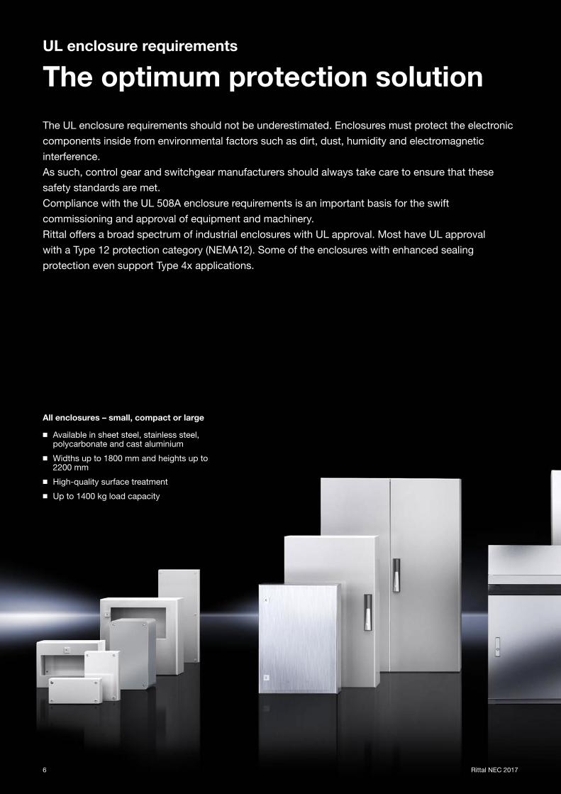
National Electrical Manufacturers Association
The National Electrical Manufacturers Association (NEMA) is a standards organisation in Washington,
USA, which publishes a number of technical standards but does not test or certify products itself.
Essentially, NEMA classifi cation outlines the protection of individuals from accidental contact with
equipment and the protection of an enclosure from external factors.
An enclosure for an industrial control panel
needs an approved protection category
(type rating). For example, if a cooling unit
is used, a cut-out will need to be made in
an enclosure.
If the supplied state of the enclosure
is changed (e.g. by a cut-out), the enclosure’s
protection category will no longer apply.
Additional UL listing under category FTTA
Additional approval under the category control number “FTTA” is particularly benefi cial for users.
This ensures that the type rating (protection category) is retained even if the enclosure has a mounting
cut-out for installation of a climate control component. As such, further testing of NEMA-classifi ed
enclosures is no longer required.
At minimum, all Rittal climate control components comply with Type 12 rating for switchgear in the
indoor zone, or Type 4x rating for use in so-called “wash down areas”.
This is a clear benefi t which simplifi es use in the 508A zone and eliminates discussions about reducing
the type rating. The additional “FTTA” approval of Rittal climate control products saves time and
money, and streamlines the UL certifi cation process.

Rittal NEC 2017 13
Optimum climate control solutions
with Rittal products
From planning through to sign-off , you can play it safe with Rittal.
Safety Protection category
Product Approvals Standard File CCNFTTA File
NEMA protection category
Air cooling
Fan-and-fi lter unitsUL 508A
CSA C22.2E76083
NITW2NITW8
E4911711)
Type 3Type 3RType 4XType 12
Roof-mounted fan
UL 508AUL 50
UL 50ECSA C22.2
E76083NITW2NITW8
E4911711) Type 12
Rack-mounted fanUL 507
CSA C22.2E171385
GPWV2GPWV8
– –
Air/air heat exchanger (wall/roof)UL1995
CSA C22.2 E117603
LZFE2LZFE8
– –
Cooling units
Blue e cooling units (wall/roof) UL 484
CSA C22.2SA8250
ACVS2ACVS8
E4911711)Type 12 and 4X
for products ending in 4
Blue e+ cooling units (wall)UL 60335-2-40
CSA C22.2SA8250
ACVSACVS7
E4911711) Type 12
Modular climate control conceptUL 484
CSA C22.2SA8250
ACVS2ACVS8
– NEMA 12
Liquid cooling
Air/water heat exchanger (wall/roof) UL 1995
CSA C22.2E117603
LZFE2LZFE8
E4911711)Type 1 and 3R for products ending in 3
Liquid Cooling PackageUL 1995
CSA C22.2E117603
LZFELZFE7
– NEMA 12
Blue e+ chillers
In progress – –
Enclosure heaters
Enclosure heatersUL 508
CSA C22.2E76083
NITW2NITW8
– –
Climate control accessories
Filter technologyUL 508A
CSA C22.2E76083
NITW2NITW8
E4911711)
Type 3Type 3RType 4
Type 4XType 12
Control/regulation UL 873 E203342XAPX
XAPX2XAPX7
– –
Up-to-date information based on Model Numbers is available on the Internet. Note on recognized: CoA included in assembly instructions.1) Applied standards: UL 50, UL 50E, UL 508A and CSA C22.2
Climate control solutions to UL-FTTA
Planning Procurement AssemblySign-off
by NRTL1 ExportSign-off
by AHJ2 Commissioning
1 National Recognized Testing Laboratory2 Authority Having Jurisdiction
Note:
Rittal climate control components need not additionally be included in the fi le of listed
panel builders (see UL 508A, table SA1.1, section 26.3). All relevant application
information can be found in the assembly, installation and operating instructions.!

14 Rittal NEC 2017
All RiLine systems have been tested for
an SCCR of 65 kA, eliminating the need
for time-consuming verifi cation.
The user need only be concerned with
SCCR compliance of the top-mounted
equipment.

Our expertise – your benefi t.
◾ Simple and fastData is clearly set out in a table, with uniform SCCR
◾ Eff ectiveClear, uniform representation of the SCCR; every component has the same SCCR
◾ Effi cientNo additional eff ort needed to increase the SCCR in various applications
Rittal NEC 2017 15
UL-tested Rittal components
RiLine busbars
Ideal for international use with an approved, cULus-listed 60 mm
busbar system.
The RiLine 60 mm busbar system from Rittal has cULus-listed approval.
This approval off ers clear advantages for international machinery and
plant manufacturers with target markets in the USA or Canada:
Minimal design input, streamlined sign-off of plant by UL (Underwriters
Laboratories) and CSA (Canadian Standards Association), and therefore
most importantly, no need to test for compliance with the Conditions of
Acceptability (COA) of all the UL-recognized components used.
Consistently tested for an SCCR of 65 kA
For eff ective support of RiLine busbar technology in enclosures, Rittal
has conducted comprehensive testing of all RiLine busbar systems and
components, and generated a uniform SCCR of 65 kA. When planning
and designing enclosures to UL 508A, users benefi t from simple,
time-saving design of the busbar systems and components. They need
only ensure that the top-mounted equipment used, such as circuit-
breakers, motor circuit-breakers and fuses, meet the specifi ed require-
ments. Tables are included in the Appendix for this purpose, and clearly
defi ne the measures needed to meet this condition.

Key and common devices for busbar systems
Device name (IEC) Device name (UL)UL Category Control Number
(CCN)
Symbol
IEC UL
Circuit-breaker Circuit breaker, moulded case and circuit breaker enclosures DIVQ1
3
Motor circuit-breaker Motor controllers, manual (Type E) NLRV3
3
Motor-starter combination Combination motor controllers (Type F) NKJH
-K130 A
3
1
2
3
Fuse Cartridge fuses, non-renewable JDDZ
16 Rittal NEC 2017
Consideration of SCCR to UL 508A
Fundamental principles
Key terms and regulations
When determining the SCCR, for example in conjunction with the use of busbars, the fi rst aspect
to consider is familiarisation with the commonly used components, terms and regulations.
The following sections therefore address these framework parameters, with reference to Standard
UL 508A Second Edition, including revisions, dated July 31, 2017.
SCCR terminology
Feeder CircuitThe feeder circuit is subject to increased requirements on creepage distances and clearances. The feeder circuit includes all devices which, viewed from the load side, are positioned after the last Branch Circuit Protective Device (BCPD).
Branch CircuitThere are no increased requirements on branch circuits with regard to creepage distances and clearances. Viewed from the load side, the branch circuit extends as far as the fi rst Branch Circuit Protective Device (BCPD).
SCCRThe Short Circuit Current Rating refers to the short-circuit withstand strength of a component, distributor, system, machine or device. Reference is often made to an overall SCCR for enclosures. As a minimum requirement, this fi gure must comply with the short-circuit rating of the available power supply.
SCPDA Short Circuit Protective Device can be used to increase the SCCR under certain conditions.
BCPDBranch Circuit Protective Devices include fuses to UL 248, circuit-breakers to UL 489, and manual and combination motor controllers type E/F to UL 508. They perform protective functions with regard to overcurrent, short-circuits and earth faults, and must be approved to a suitable standard. In terms of load, the last BCPD represents the boundary between the feeder and branch circuit.
CCNThe Category Control Number classifi es devices and components into categories. Which categories may be used in the application are defi ned, for example, in UL 508A under Table SA1.1.
IpThe peak let-through is the maximum current which a current- limiting device will allow through, in relation to a defi ned SCCR.

Rittal NEC 2017 17
What is a “high fault” SCCR?
A High Fault Short Circuit Rating is the SCCR
specifi ed on or in the device documentation, and
is greater than the Standard Fault Short Circuit
Current Rating shown in UL 508A, Table SB 4.1.
Compliance with the high fault SCCR may be
conditional upon a current-limiting protective
device being positioned upstream of the
components or system.
Which short circuit-limiting protective and switching devices SCPD can be used in the feeder
circuit to increase the SCCR?
Short circuit-limiting protective devices (SCPDs) may be used to increase the SCCR value of an
enclosure. If the peak let-through of an SCPD (feeder fuse/feeder breaker) is less than the SCCR of
the relevant component in the branch circuit, that component’s SCCR may be raised to the feeder
SCCR under consideration.
The following components may be used as SCPDs:
I Circuit breaker, moulded case and circuit
breaker enclosures “current limiting”
Only MCCBs specifi cally labelled as “current
limiting” may be used, because the current-
limiting function must be part of the approval.
This current-limiting property must be verifi ed
at regular intervals by the manufacturer.
II Cartridge fuses
Here too, the manufacturer must provide
regular verifi cation of the peak let-throughs.
For example, the fuse type must be a fuse class
CC, class J... listed under UL 248. The peak
let-throughs (Ip) shown in Table SB4.2 of UL 508A
apply. In this connection, it is important to note
that the selected current-limiting protective device
(SCPD) may only be used to increase the SCCR
of components in the branch circuit. The SCCR of
components in the feeder circuit cannot be
improved in this way.
The following components may be used as BCPD:
I Fuse with UL Category Control Number JDDZ
II Circuit breaker, moulded case circuit breaker
enclosures with UL Category Control Number
DIVQ
III Manual motor controller with
UL Category Control Number NLRV
IV Combination motor controller with
UL Category Control Number NKJH
Use of a “Serial Rating”
A serial rating cannot be applied to any random
combination of a current-limiting device with
another device, such as a contactor. Such
untested combinations are not classed as
a combination motor controller in accordance
with UL 508.
A serial rating of two or more devices must
be tested in this combination, and can only
be used to increase the SCCR in this exact
combination of devices. If no serial rating exists
for this combination, the lowest SCCR of the
two individual devices applies.
SCCR regulations

18 Rittal NEC 2017
Important for UL 508A: Short-circuit withstand strength
SCCR to the lowest common
denominator
Determining the overall SCCR in the enclosure
Determining the SCCR (Short Circuit Current Rating) entails ascertaining which components or
tested combinations in the main circuits inside the enclosure have the lowest SCCR. The lowest
individual SCCR determines the SCCR of the overall enclosure (overall SCCR). An enclosure’s
SCCR ultimately determines whether the application’s short-circuit withstand strength require-
ments match the available SCCR from the power supply. This usually aff ects power circuits.
With control circuits, it is not necessary to determine the SCCR, because transformers are
usually connected upstream. To calculate the overall SCCR of an enclosure, the planner must
consider the individual SCCR value of each component and device, from the load side through
to the feed-in point.
Plan ahead, ensure a high level of effi ciency
The overall SCCR should be taken into account at the planning stage, since by selecting correct
components and devices, and also by using suitable application techniques for short circuit
current-limiting devices, it is usually possible to achieve a cost-eff ective solution with the
required SCCR. Considering the SCCR at a later date, for example at the time of commissioning,
could lead to higher material and modifi cation costs if the required SCCR is not met, causing
costs to rise exponentially.
The verifi cation procedure as set out in
the SB supplement to UL 508A
The NEC off ers two verifi cation options. The
fi rst of these is by having the system tested
to a recognised verifi cation procedure such
as that set out in the SB supplement to
UL 508A. As testing is always time-
consuming and costly in terms of materials
and personnel, this verifi cation procedure
has emerged as an important tool.

Rittal NEC 2017 19
Diagrammatic representation of the procedure for determining the overall SCCR of an enclosure to UL 508A
SB4.2
Ascertain the SCCR of the individual components in the power circuit
SB4.3
Ascertain the feeder components that may be used to limit the short-circuit.
SB4.4
Determine the overall SCCR of the enclosure
4.2.1 List those devices that are not covered by the SCCR approach
4.2.2 a) Determine the SCCR using the rating plate or manufacturer documentation of the device/component
4.2.2 b) Determine the SCCR in accordance with Table SB4.1
4.2.2 c) Determine the SCCR by testing to UL 508
4.3.1 Limit the short circuit current with a transformer in the feeder
4.3.2 Increase the SCCR by using a current- limiting circuit-breaker in the feeder
4.3.3 Increase the SCCR by using current- limiting fuses in the feeder
4.4.1 Determine the smallest SCCR of all power circuits including a control current protective device
4.4.4 a) For enclosures with only one power circuit and no outgoing protective device (BCPD) within the enclosure
4.4.4 b) For enclosures with only one power circuit and an outgoing protective device (BCPD) within the enclosure
4.4.4 c) For enclosures with multiple outgoing circuits and feeder components such as circuit-breakers, disconnectors, busbar systems, terminal blocks, overcurrent protective devices
Further information on calculation
of the SCCR can be found in
the SB Supplement to UL 508A.

20 Rittal NEC 2017
Consideration of SCCR to UL 508A
Practical example
Consideration of SCCR incorporating a busbar assembly
Busbars are a standard feature in modern enclosure assembly.
RiLine systems are all tested for an SCCR of 65 kA.
This therefore eliminates the need for time-consuming verifi cation.
The user need only be concerned with the SCCR compliance of the top-mounted equipment.
Here is an example of SCCR in busbar systems.

SCCR in a busbar assembly
Fe
ed
er
Cir
cu
itB
CP
DB
ran
ch
Cir
cu
itL
oa
d
SV 9340.05065 kA, 480 V with circuit breakerCCN: DIVQmax. 600 A
SV 9345.71065 kA, 480 V with circuit breakerCCN: DIVQmax. 600 A
SV 9342.51065 kA, 480 V with circuit breakerCCN: DIVQmax. 125 A
SV 9340.31065 kA, 480 V with manual motor controllerCCN: NLRV max. 30 A
SV 9340.39065 kA, 480 V with manual motor controllerCCN: NKJHmax. 30 A
SV 9340.31065 kA, 480 V with Class CC fuse holderCCN: JDDZmax. 30 A
Rittal NEC 2017 21
DIVQ 600 A
3
DIVQ 125 A
3
JDDZ30 A
3
65 kAtested
3+PE
NLRV30 A
M3
1
2
3+PE
NKJH30 A
1
2
M3
2
1
1
2
The rating data for the RiLine components used in this practical example may be found on page 22/23.

22 Rittal NEC 2017
Model No. Code
SCCR (Short Circuit Current Rating)
kA
Rated voltage V AC
SCPD (Short Circuit
Protective Device) type
SCPD rating
max. A
CCN (Category Control
Number)
Busbar dimensions
W x Hmm
Distance between busbar
supportsmm
Flat copper bar system
9340.0509340.004
Busbar support (UL), 3-pole, 60 mm
65
480 Circuit breaker 600 DIVQ
30 x 5/10 250Centre-to-centre spacing, for E-Cu 15 x 5 – 30 x 10 mm
600 Fuse Class L 800 JDDZ
PLS 800 busbar system
9341.050Busbar support PLS 800 (UL), 3-pole, 60 mm centre-to-centre spacing
65480 Circuit breaker 600 DIVQ
PLS 800 150600 Fuse Class J 600 JDDZ
PLS 1600 busbar system
9342.050Busbar support PLS 1600, 3-pole, 60 mm centre-to-centre spacing
65
600 Fuse Class L 1400JDDZ
PLS 1600
250
600 Fuse Class L 1600 100
9342.004Busbar support PLS 1600 PLUS, 4-pole, 60 mm centre-to-centre spacing
480 Circuit breaker 1200 DIVQ 250
OM adaptors
9340.7609340.780
OM adaptor, AWG 12, 3-pole, W = 45 mm
65
600 Fuse Class J 30 JDDZ
30 x 5/10PLS 800
PLS 1600250
480Combination Motor
Controller32 NKJH
9340.3109340.3209340.3409340.370
OM adaptor, AWG 12, 3-pole, W = 45 mm
600 Fuse Class J 30 JDDZ
480Combination Motor
Controller32 NKJH
9340.400 OM adaptor, AWG 12, 3-pole, W = 90 mm
600 Fuse Class J 30 NLRV
480Manual Motor Controller
Combination Motor Controller
32 NKJH
9340.3509340.3809340.3909340.770
OM adaptor, AWG 10, 3-pole, W = 45 mm
600 Fuse Class J 30 JDDZ
480Combination Motor
Controller32 NKJH
9340.4609340.470
OM adaptor, AWG 10, 3-pole, W = 55 mm
600 Fuse Class J 30 NLRV
480Manual Motor Controller
Combination Motor Controller
32 NKJH
9340.7209340.7309340.7409340.750
OM adaptor, AWG 8, 3-pole, W = 55 mm
600 Fuse Class J 60 JDDZ
480Manual Motor Controller
Combination Motor Controller
63NLRV
NKJH
9340.710 OM adaptor, AWG 8, 3-pole, W = 75 mm
600 Fuse Class J 60 JDDZ
480Manual Motor Controller
Combination Motor Controller
63NLRVNKJH
9340.4109340.4309340.450
OM adaptor, AWG 6, 3-pole, W = 55 mm
600 Fuse Class J 60 JDDZ
480Manual Motor Controller
Combination Motor Controller
63NLRVNKJH
9340.700 OM adaptor, AWG 6, 3-pole, W = 75 mm
600 Fuse Class J 60 JDDZ
480Manual Motor Controller
Combination Motor Controller
63NLRVNKJH
RiLine busbars
Overview of SCCR
Initial overview of UL 508A-compliant RiLine busbars and components
The following table lists all the key products covered by the 65 kA short circuit current rating,
but does not include all UL-listed items in the RiLine product range.
Selection of RiLine UL busbar systems and components compliant with UL 508A

Rittal NEC 2017 23
Model No. Code
SCCR (Short Circuit Current Rating)
kA
Rated voltage V AC
SCPD (Short Circuit
Protective Device)type
SCPD rating
max. A
CCN (Category Control
Number)
Busbar dimensions
W x Hmm
Distance between busbar
supportsmm
Busbar connection adaptors
9342.2009342.210
Busbar connection adaptor 63 A, 3-pole
65
600 Fuse Class J 60 JDDZ
12 x 5 – 30 x 10PLS 800
PLS 1600250
480 Manual Motor Controller 65 NLRV
9342.240 Busbar connection adaptor 125 A, 3-pole600 Fuse Class J 400 JDDZ
480 Circuit breaker 125 DIVQ
9342.224 Busbar connection adaptor 125 A, 4-pole600 Fuse Class J 400 JDDZ
480 Circuit breaker 125 DIVQ
9342.2509342.270
Busbar connection adaptor 250 A, 3-pole600 Fuse Class J 400 JDDZ
480 Circuit breaker 250 DIVQ
9342.254 Busbar connection adaptor 250 A, 4-pole600 Fuse Class J 400 JDDZ
480 Circuit breaker 250 DIVQ
9342.311 Connection block 800 A, 1-pole600 Fuse Class L 800 JDDZ
480 Circuit breaker 600 DIVQ
9342.310Busbar connection adaptor 800 A (3 x 1-pole), cable outlet at the top/bottom (60 mm)
600 Fuse Class L 800 JDDZ
480 Circuit breaker 600 DIVQ
9342.314Busbar connection adaptor 800 A, add-on kit for SV 9342.310 (4-pole layout)
600 Fuse Class L 800 JDDZ
480 Circuit breaker 600 DIVQ
9342.2909342.300
Busbar connection adaptor 800 A, 3-pole600 Fuse Class L 800 JDDZ
480 Circuit breaker 600 DIVQ
9342.321 Connection block 1600 A, 1-pole600 Fuse Class L 1600 JDDZ
480 Circuit breaker 1200 DIVQ
9342.320Busbar connection adaptor 1600 A (3 x 1-pole), cable outlet at the top/bottom (60 mm)
600 Fuse Class L 1600 JDDZ
480 Circuit breaker 1200 DIVQ
9342.324Busbar connection adaptor 1600 A, add-on kit for SV 9342.320 (4-pole layout)
600 Fuse Class L 1600 JDDZ
480 Circuit breaker 1200 DIVQ
Circuit-breaker component adaptors
9342.4009342.410
Circuit-breaker component adaptor 100 A, 3-pole
65 480
Manual Motor Controller 100 NLRV
30 x 5/10PLS 800
PLS 1600250
9342.5409342.550
Circuit-breaker component adaptor 125 A, 3-pole
Circuit breaker
125
DIVQ
9342.5049342.514
Circuit-breaker component adaptor 125 A, 4-pole
9342.6109345.6009345.610
Circuit-breaker component adaptor 250 A, 3-pole
250
9345.6049345.614
Circuit-breaker component adaptor 250 A, 4-pole
9345.7209345.730
Circuit-breaker component adaptor 400 A, 3-pole
400
9345.7009345.710
Circuit-breaker component adaptor 630 A, 3-pole
600
Fuse holder
9345.100Fuse holder class J, 61 – 100 A, 3-pole (60 mm)
100 600 Fuse Class J
100
JDDZ30 x 5/10PLS 800
PLS 16002509345.200
Fuse holder class J, 101 – 200 A, 3-pole (60 mm)
200
9345.400Fuse holder class J, 201 – 400 A, 3-pole (60 mm)
400
Accessories
3079.010Universal support for laminated copper bars up to 2 x 63 x 10 mm
65 480 Circuit breaker 1200 DIVQ2 x 63 x 10 mm
lam. Cu250
Further details can be found at www.rittal.com
For clarity, other tested short-circuit ratings and accessory components such as covers,
base trays, busbars etc. are not shown here. This information can be viewed in Rittal UL-File E191125
or at www.rittal.com on the relevant product pages, or in the online certifi cate for UL-File E191125.

www.rittal.com/contact
You can fi nd the contact details of all
Rittal companies throughout the world here.
◾ Enclosures
◾ Power Distribution
◾ Climate Control
◾ IT Infrastructure
◾ Software & Services
XW
W00139E
N1803