Embed Size (px)
Citation preview

Machine Elements and Design UQF 6 Mechanical Engineering
1 | P a g e
Chain Drives 1. Introduction
In Belt and Rope drives slipping may occur. In order to avoid slipping, steel chains are used. The
chains are made up of a number of rigid links which are hinged together by pin joints in order to
provide the necessary flexibility for wrapping round the driving and driven wheels. These wheels have
projecting teeth of special profile and fit into the corresponding recesses in the links of the chain as
shown in Fig. 1. The toothed wheels are known as *sprocket wheels or simply sprockets. The
sprockets and the chain are thus constrained to move together without slipping and ensures perfect
velocity ratio.
The chains are mostly used to transmit motion and power from one shaft to another, when the
centre distance between the shafts is short such as in bicycles, motorcycles, agricultural
machinery, conveyors, rolling mills, road rollers etc. The chains may also be used for long centre
distance of up to 8 metres. The chains are used for velocities up to 25 m/s and for power up to
110 kW. In some cases, higher power transmission is also possible.
2. Advantages and Disadvantages of Chain Drive over Belt or Rope Drive
Advantages
1. As no slip takes place during chain drive, hence perfect velocity ratio is obtained
2. Since the chains are made of metal, therefore they occupy less space in width than a belt or
rope drive
3. It may be used for both long as well as short distances
4. It gives high transmission efficiency (up to 98 percent)
5. It gives less load on the shafts

Machine Elements and Design UQF 6 Mechanical Engineering
2 | P a g e
6. It has the ability to transmit motion to several shafts by one chain only
7. It transmits more power than belts
8. It permits high speed ratio of 8 to 10 in one step
9. It can be operated under adverse temperature and atmospheric conditions
Disadvantages
1. The production cost of chains is relatively high
2. The chain drive needs accurate mounting and careful maintenance, particularly lubrication
and slack adjustment
3. The chain drive has velocity fluctuations especially when unduly stretched
3. Terms Used in Chain Drive
1. Pitch of chain: It is the distance between the hinge centre of a link and the corresponding hinge
centre of the adjacent link, as shown in Fig. 2. It is usually denoted by p.
2. Pitch circle diameter of chain sprocket: It is the diameter of the circle on which the hinge
centres of the chain lie, when the chain is wrapped round a sprocket as shown in Fig. 2. The points A, B,

Machine Elements and Design UQF 6 Mechanical Engineering
3 | P a g e
C, and D are the hinge centres of the chain and the circle drawn through these centres is called pitch
circle and its diameter (D) is known as pitch circle diameter.
4. Relation between Pitch and Pitch Circle Diameter
A chain wrapped round the sprocket is shown in Fig. 2. Since the links of the chain are rigid, therefore
pitch of the chain does not lie on the arc of the pitch circle. The pitch length becomes a chord.
Consider one pitch length AB of the chain subtending an angle θ at the centre of sprocket (or pitch
circle),
5. Velocity Ratio of Chain Drives
The velocity ratio of a chain drive is given by

Machine Elements and Design UQF 6 Mechanical Engineering
4 | P a g e
6. Length of Chain and Centre Distance
An open chain drive system connecting the two sprockets is shown in Fig. 3.

Machine Elements and Design UQF 6 Mechanical Engineering
5 | P a g e
7. Classification of Chains
The chains, on the basis of their use, are classified into the following three groups:
1. Hoisting and hauling (or crane) chains,
2. Conveyor (or tractive) chains, and
3. Power transmitting (or driving) chains.
8. Hoisting and Hauling Chains
These chains are used for hoisting and hauling purposes and operate at a maximum velocity of 0.25
m/s. The hoisting and hauling chains are of the following two types:
1. Chain with oval links. The links of this type of chain are of oval shape, as shown in Fig. 4 (a). Such
type of chains are used only at low speeds such as in chain hoists and in anchors for marine works.
2. Chain with square links. The links of this type of chain are of square shape, as shown in Fig. 4 (b).
Such types of chains are used in hoists, cranes, dredges.
9. Conveyor Chains
These chains are used for elevating and conveying the materials continuously at a speed up to 2 m / s.
The conveyor chains are of the following two types:
1. Detachable or hook joint type chain, Fig. 5 (a), and 2. Closed joint type chain, Fig. 5 (b)

Machine Elements and Design UQF 6 Mechanical Engineering
6 | P a g e
Conveyor chains are usually made of malleable cast iron and run at slow speeds of about 0.8 to 3 m/s.
10. Power Transmitting Chains
These chains are used for transmission of power, when the distance between the centres of shafts is
short. These chains have provision for efficient lubrication. The power transmitting chains are of the
following three types.
1. Block or bush chain. A block or bush chain is shown in Fig.6. This type of chain was used in the
early stages of development in the power transmission.
Fig. 6. Block or bush chain.
It produces noise when approaching or leaving the teeth of the sprocket because of rubbing between
the teeth and the links. Such type of chains is used to some extent as conveyor chain at small speed.
2. Bush roller chain. A bush roller chain as shown in Fig. 7 consists of outer plates or pin link plates,
inner plates or roller link plates, pins, bushes and rollers. A pin passes through the bush which is secured
in the holes of the roller between the two sides of the chain. The rollers are free to rotate in the bush
protect the sprocket wheel teeth against wear. The pins, bushes and rollers are made of alloy steel.

Machine Elements and Design UQF 6 Mechanical Engineering
7 | P a g e
The roller chains are standardized and manufactured on the basis of pitch. These chains are
available in single-row or multi-row roller chains such as simple, duplex or triplex strands, as shown in
Fig 8.
3. Silent chain. A silent chain (also known as inverted tooth chain) is shown in Fig 9.
It is designed to eliminate the evil effects caused by stretching and to produce noiseless running. When
the chain stretches and the pitch of the chain increases, the links ride on the teeth of the sprocket wheel
at a slightly increased radius. This automatically corrects the small change in the pitch. There is no
relative sliding between the teeth of the inverted tooth chain and the sprocket wheel teeth. When
properly lubricated, this chain gives durable service and runs very smoothly and quietly.
The various types of joints used in a silent chain are shown in Fig 10.

Machine Elements and Design UQF 6 Mechanical Engineering
8 | P a g e
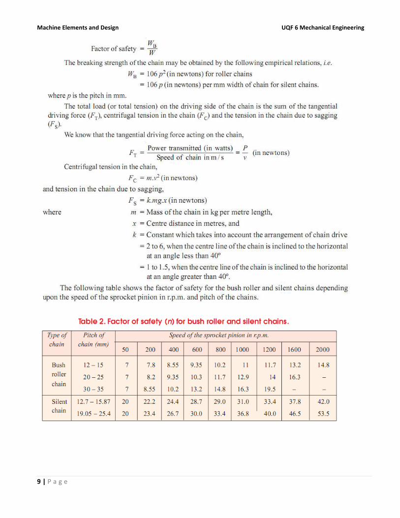
12. Factor of Safety for Chain Drives
The factor of safety for chain drives is defined as the ratio of the breaking strength (W) of the chain to
the total load on the driving side of the chain (W). Mathematically,
Machine Elements and Design UQF 6 Mechanical Engineering
9 | P a g e
Machine Elements and Design UQF 6 Mechanical Engineering
10 | P a g e
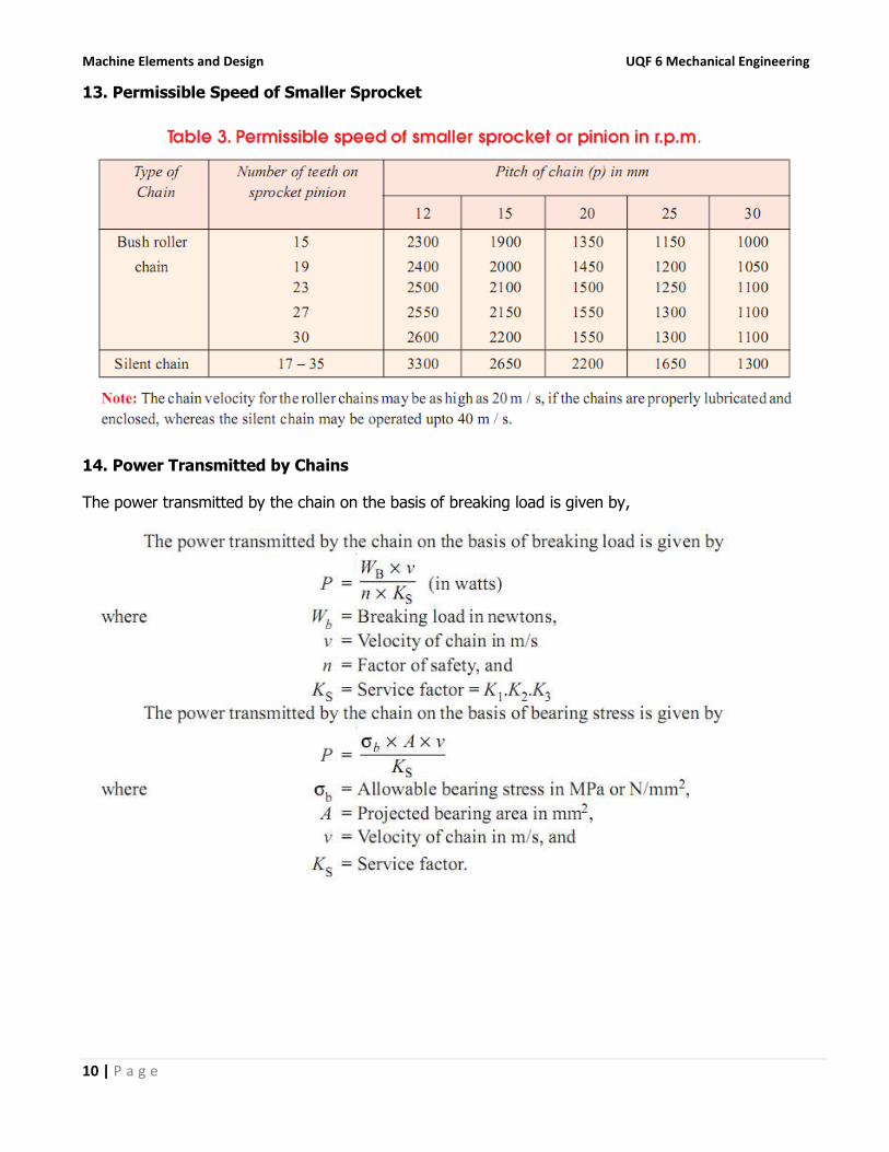
13. Permissible Speed of Smaller Sprocket
14. Power Transmitted by Chains
The power transmitted by the chain on the basis of breaking load is given by,

Machine Elements and Design UQF 6 Mechanical Engineering
11 | P a g e
15. Number of Teeth on the Smaller or Driving Sprocket or Pinion
Consider an arrangement of a chain drive in which the smaller or driving sprocket has only four teeth, as
shown in Fig. 11 (a). Let the sprocket rotates anticlockwise at a constant speed of N r.p.m. The chain
link AB is at a distance of d/2 from the centre of the sprocket and its linear speed is given by,

Machine Elements and Design UQF 6 Mechanical Engineering
12 | P a g e
16. Maximum Speed for Chains
The maximum allowable speed for the roller and silent chains, depending upon the number of teeth on
the smaller sprocket or pinion and the chain pitch is shown in the following table.


![ELEMENTS OF MECHANICAL ENGINEERING [15EME14 / 24]alphace.ac.in/downloads/notes/basic science/15EME14_NOTES.pdf · ELEMENTS OF MECHANICAL ENGINEERING ... ELEMENTS OF MECHANICAL ENGINEERING](https://img.pdfslide.net/doc/110x75/5b81ea017f8b9a2b678d762b/elements-of-mechanical-engineering-15eme14-24-science15eme14notespdf.jpg)