Embed Size (px)
Citation preview
Machine Vision Projects with NI myRIO - PREVIEW
This courseware title will be released in its entirety in early 2015. This preview of the material is
available now for professors and students to review and test.
With the preview material you will learn fundamental concepts necessary to create a myRIO vision
application in LabVIEW as listed below.
Specific PREVIEW Topics
1. Acquire an image of a coin and measure the diameter
2. Measure a camera's pixel aspect ration
3. Determine camera to object distance
4. Calculate the field of view
5. Calibrate a camera to use real world units
6. Correct lens distortion and tangential distortion
Full List of Topics to be Covered in Complete Version
Part I
1. Application Development Flow
2. Camera Set-up
3. Image Buffer Memory Management in LabVIEW
Part II
1. Acquire a calibrated image from a webcam
2. Detect and count objects passing by field of view
3. Identify and sort objects by shape
4. Identify and sort objects by color
5. Inspect a part for missing pieces
6. Auto-pan the webcam to track objects by color
7. Read a legacy meter that lacks a digital data communications interface
8. Manage inventory with handwritten labels and barcodes
9. Inspect an object for texture defects
10. Inspect an object compared to golden template
11. Measure depth information from stereo webcams
12. Measure optical flow
Final Version will Contain Full Lab Exercise Manual PDF
LabVIEW Project Files
30+ Detailed Instructional Videos
Required Software NI LabVIEW
NI LabVIEW myRIO Module
NI LabVIEW Vision Development
Module
Required Hardware NI myRIO
USB Webcam
Machine Vision Projects with NI myRIO
Ed DoeringElectrical and Computer Engineering Department
Rose-Hulman Institute of Technology
DRAFT: September 2014
iv
Printed September 17, 2014. Download the latest version at http://www.ntspress.com.
c©2015 National Technology and Science Press.
All rights reserved. Neither this book, nor any portion of it, may be copiedor reproduced in any form or by any means without written permission ofthe publisher.
NTS Press respects the intellectual property of others, and we ask our read-ers to do the same. This book is protected by copyright and other intel-lectual property laws. Where the software referred to in this book maybe used to reproduce software or other materials belonging to others, youshould use such software only to reproduce materials that you may repro-duce in accordance with the terms of any applicable license or other legalrestriction.
LabVIEW and National Instruments are trademarks of National Instru-ments.
All other trademarks or product names are the property of their respectiveowners.
Additional Disclaimers: The reader assumes all risk of use of this book andof all information, theories, and programs contained or described in it. Thisbook may contain technical inaccuracies, typographical errors, other errorsand omissions, and out-of-date information. Neither the author nor thepublisher assumes any responsibility or liability for any errors or omissionsof any kind, to update any information, or for any infringement of anypatent or other intellectual property right.
Neither the author nor the publisher makes any warranties of any kind, in-cluding without limitation any warranty as to the sufficiency of the bookor of any information, theories, or programs contained or described in it,and any warranty that use of any information, theories, or programs con-tained or described in the book will not infringe any patent or other in-tellectual property right. THIS BOOK IS PROVIDED “AS IS.” ALL WAR-RANTIES, EITHER EXPRESS OR IMPLIED, INCLUDING, BUT NOT LIM-ITED TO,ANY AND ALL IMPLIED WARRANTIES OF MERCHANTABIL-ITY, FITNESS FOR A PARTICULAR PURPOSE, AND NON-INFRINGEMENTOF INTELLECTUAL PROPERTY RIGHTS, ARE DISCLAIMED.

v
No right or license is granted by publisher or author under any patent orother intellectual property right, expressly, or by implication or estoppel.
IN NO EVENT SHALL THE PUBLISHER OR THE AUTHOR BE LIABLEFOR ANY DIRECT, INDIRECT, SPECIAL, INCIDENTAL, COVER, ECO-NOMIC, OR CONSEQUENTIAL DAMAGES ARISING OUT OF THIS BOOKOR ANY INFORMATION, THEORIES, OR PROGRAMS CONTAINED ORDESCRIBED IN IT, EVEN IF ADVISED OF THE POSSIBILITY OF SUCHDAMAGES, AND EVEN IF CAUSED OR CONTRIBUTED TO BY THENEGLIGENCE OF THE PUBLISHER, THE AUTHOR, OR OTHERS. Ap-plicable law may not allow the exclusion or limitation of incidental or con-sequential damages, so the above limitation or exclusion may not apply toyou.

vi
Contents
1 Application Development Flow 1
2 Camera Setup 9
A MXP and MSP Connector Diagrams 15
B Build a Stand-Alone Application 19
C Video Tutorial Links 21

viii CONTENTS
1 Application Development Flow
1.1 Synopsis
The machine vision projects in this manual generally follow a well-definedapplication development flow from original concept through validation of theapplication on the NI myRIO target. The particular details vary consider-ably from one project to the next, but the overall development flow remainsthe same.
In this project you will gain experience with the machine vision appli-cation development flow based on NI Vision Assistant and NI LabVIEWfor the NI myRIO hardware target.
NOTE: The application development flow described here may also beused to create a desktop application in case you do not have access tothe NI myRIO target.
1.2 Objectives
1. Gain experience with the machine vision application developmentflow
2. Implement a simple machine vision application to measure a coin’sdiameter.
1.3 Deliverables
1. Hardcopy of all LabVIEW block diagrams and front panels that youdevelop
2 LABORATORY PROJECT 1. APPLICATION DEVELOPMENT FLOW
2. Screen captures of NI Vision Assistant script and individual step dia-log boxes
3. Lab report or notebook formatted according to instructor’s require-ments
1.4 Required Resources
1. NI Vision Assistant
2. NI LabVIEW
3. NI myRIO
4. Ruler with millimeter and centimeter marks
5. Several coins of various sizes
6. Caliper
7. Black felt fabric
8. Webcam
9. Table-top copy stand
1.5 Preparation
Figure ??? visualizes the application development flow as an eleven-stepprocedure. Familiarize yourself with these important considerations foreach step of the development flow:
1. Define the requirements of the machine vision application
• Processing objectives, e.g., measurement and gauging, classifi-cation and sorting, and bar code recognition
• Throughput measured in parts processed per second
• Minimum feature size and number of pixels allocated to this fea-ture
• Size of the field of view
• I/O devices for part sensing, position control, and informationdisplay
LABORATORY PROJECT 1. APPLICATION DEVELOPMENT FLOW 3
2. Configure the image acquistion system
• Determine the minimum feature size in physical units such asmillimeters
• Determine the number of pixels to allocate to the minimum-sized feature, and thereby obtain the required spatial resolutionin millimeters per pixel
• Select the camera resolution and camera-to-object distance toachieve the required spatial resolution, field of view (FOV), andframe rate
• Arrange the lighting system to obtain high contrast for the fea-tures of interest and to suppress distracting background featuresthat complicate subsequent software processing and add unnec-essary computational cost
• Use grayscale images for efficiency unless color is required forthe application; color images tend to slow down the display, es-pecially at higher resolutions
3. Acquire representative images
• Connect the camera to the desktop
• Use Vision Assistant to collect images over the range of possibleconditions
• Use manual camera settings, especially focus; record the settingsfor later use
• Collect an image of one or more calibration targets using thesame camera settings
4. Calibrate the camera when the application requires real-world units
• Use the calibration target image(s) collected in the previous step
• Use the simplest calibration technique that achieves the requiredmeasurement accuracy
• Do not disturb the image acquisition setup once calibrated
5. Develop the processing script
• Use the stand-alone version of NI Vision Assistant
• Begin with the color-to-luminance step (unless the applicationrequires color, of course)
4 LABORATORY PROJECT 1. APPLICATION DEVELOPMENT FLOW
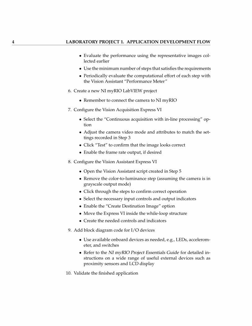
• Evaluate the performance using the representative images col-lected earlier
• Use the minimum number of steps that satisfies the requirements
• Periodically evaluate the computational effort of each step withthe Vision Assistant “Performance Meter”
6. Create a new NI myRIO LabVIEW project
• Remember to connect the camera to NI myRIO
7. Configure the Vision Acquisition Express VI
• Select the “Continuous acquisition with in-line processing” op-tion
• Adjust the camera video mode and attributes to match the set-tings recorded in Step 3
• Click “Test” to confirm that the image looks correct
• Enable the frame rate output, if desired
8. Configure the Vision Assistant Express VI
• Open the Vision Assistant script created in Step 5
• Remove the color-to-luminance step (assuming the camera is ingrayscale output mode)
• Click through the steps to confirm correct operation
• Select the necessary input controls and output indicators
• Enable the “Create Destination Image” option
• Move the Express VI inside the while-loop structure
• Create the needed controls and indicators
9. Add block diagram code for I/O devices
• Use available onboard devices as needed, e.g., LEDs, accelerom-eter, and switches
• Refer to the NI myRIO Project Essentials Guide for detailed in-structions on a wide range of useful external devices such asproximity sensors and LCD display
10. Validate the finished application
LABORATORY PROJECT 1. APPLICATION DEVELOPMENT FLOW 5
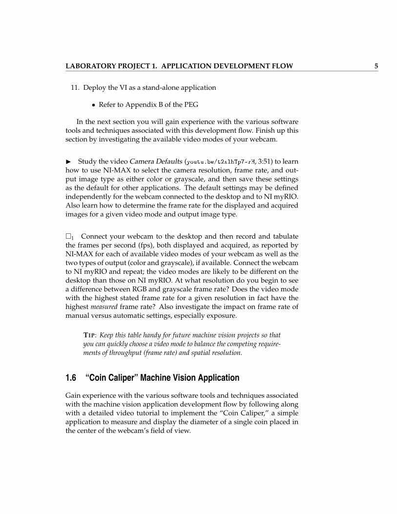
11. Deploy the VI as a stand-alone application
• Refer to Appendix B of the PEG
In the next section you will gain experience with the various softwaretools and techniques associated with this development flow. Finish up thissection by investigating the available video modes of your webcam.
I Study the video Camera Defaults (youtu.be/t2xlhTp7-rM, 3:51) to learnhow to use NI-MAX to select the camera resolution, frame rate, and out-put image type as either color or grayscale, and then save these settingsas the default for other applications. The default settings may be definedindependently for the webcam connected to the desktop and to NI myRIO.Also learn how to determine the frame rate for the displayed and acquiredimages for a given video mode and output image type.
�1 Connect your webcam to the desktop and then record and tabulatethe frames per second (fps), both displayed and acquired, as reported byNI-MAX for each of available video modes of your webcam as well as thetwo types of output (color and grayscale), if available. Connect the webcamto NI myRIO and repeat; the video modes are likely to be different on thedesktop than those on NI myRIO. At what resolution do you begin to seea difference between RGB and grayscale frame rate? Does the video modewith the highest stated frame rate for a given resolution in fact have thehighest measured frame rate? Also investigate the impact on frame rate ofmanual versus automatic settings, especially exposure.
TIP: Keep this table handy for future machine vision projects so thatyou can quickly choose a video mode to balance the competing require-ments of throughput (frame rate) and spatial resolution.
1.6 “Coin Caliper” Machine Vision Application
Gain experience with the various software tools and techniques associatedwith the machine vision application development flow by following alongwith a detailed video tutorial to implement the “Coin Caliper,” a simpleapplication to measure and display the diameter of a single coin placed inthe center of the webcam’s field of view.
6 LABORATORY PROJECT 1. APPLICATION DEVELOPMENT FLOW
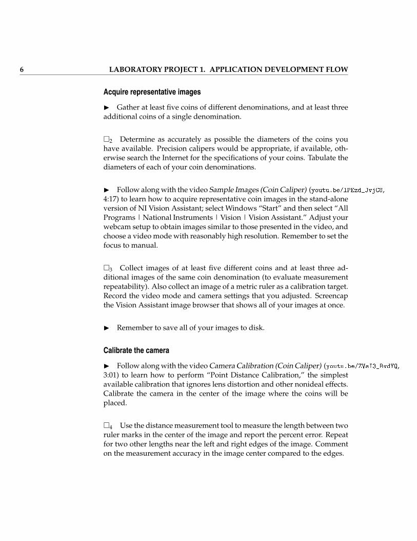
Acquire representative images
I Gather at least five coins of different denominations, and at least threeadditional coins of a single denomination.
�2 Determine as accurately as possible the diameters of the coins youhave available. Precision calipers would be appropriate, if available, oth-erwise search the Internet for the specifications of your coins. Tabulate thediameters of each of your coin denominations.
I Follow along with the video Sample Images (Coin Caliper) (youtu.be/lPEzd_JvjC8,4:17) to learn how to acquire representative coin images in the stand-aloneversion of NI Vision Assistant; select Windows “Start” and then select “AllPrograms | National Instruments | Vision | Vision Assistant.” Adjust yourwebcam setup to obtain images similar to those presented in the video, andchoose a video mode with reasonably high resolution. Remember to set thefocus to manual.
�3 Collect images of at least five different coins and at least three ad-ditional images of the same coin denomination (to evaluate measurementrepeatability). Also collect an image of a metric ruler as a calibration target.Record the video mode and camera settings that you adjusted. Screencapthe Vision Assistant image browser that shows all of your images at once.
I Remember to save all of your images to disk.
Calibrate the camera
I Follow along with the video Camera Calibration (Coin Caliper) (youtu.be/ZVsI3_BvdYQ,3:01) to learn how to perform “Point Distance Calibration,” the simplestavailable calibration that ignores lens distortion and other nonideal effects.Calibrate the camera in the center of the image where the coins will beplaced.
�4 Use the distance measurement tool to measure the length between tworuler marks in the center of the image and report the percent error. Repeatfor two other lengths near the left and right edges of the image. Commenton the measurement accuracy in the image center compared to the edges.
LABORATORY PROJECT 1. APPLICATION DEVELOPMENT FLOW 7
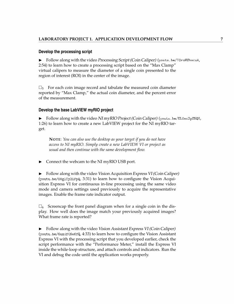
Develop the processing script
I Follow along with the video Processing Script (Coin Caliper) (youtu.be/I0roHVhwcuA,2:54) to learn how to create a processing script based on the “Max Clamp”virtual calipers to measure the diameter of a single coin presented to theregion of interest (ROI) in the center of the image.
�5 For each coin image record and tabulate the measured coin diameterreported by “Max Clamp,” the actual coin diameter, and the percent errorof the measurement.
Develop the base LabVIEW myRIO project
I Follow along with the video NI myRIO Project (Coin Caliper) (youtu.be/EL0nc2pZ5Q0,1:26) to learn how to create a new LabVIEW project for the NI myRIO tar-get.
NOTE: You can also use the desktop as your target if you do not haveaccess to NI myRIO. Simply create a new LabVIEW VI or project asusual and then continue with the same development flow.
I Connect the webcam to the NI myRIO USB port.
I Follow along with the video Vision Acquisition Express VI (Coin Caliper)(youtu.be/OVglTy2lFpQ, 3:31) to learn how to configure the Vision Acqui-sition Express VI for continuous in-line processing using the same videomode and camera settings used previously to acquire the representativeimages. Enable the frame rate indicator output.
�6 Screencap the front panel diagram when for a single coin in the dis-play. How well does the image match your previously acquired images?What frame rate is reported?
I Follow along with the video Vision Assistant Express VI (Coin Caliper)(youtu.be/6uxKf46o6fQ, 4:33) to learn how to configure the Vision AssistantExpress VI with the processing script that you developed earlier, check thescript performance with the “Performance Meter,” install the Express VIinside the while-loop structure, and attach controls and indicators. Run theVI and debug the code until the application works properly.
8 LABORATORY PROJECT 1. APPLICATION DEVELOPMENT FLOW
�7 Screencap the front panel for several coins. Compare the measureddiameters to the known diameters. Report the typical frame rate, too.
I Follow along with the video I/O Devices (Coin Caliper) (youtu.be/UXy1LH-uLXY,3:01) to learn how to add the NI myRIO onboard LEDs to indicate whetherthe coin diameter is larger or smaller than a threshold value. This verysimple example illustrates how to add I/O devices to the application.
Validate the application
�8 Test your completed “Coin Caliper” application. How robust is theapplication? For example, how much variation do you see in the diametermeasurement with the coin “just sitting there” in the display? How dochanges in illumination affect the measurement?
Deploy the VI as a stand-alone application
I Study the video Deploy a Stand-Alone Application (youtu.be/JXoJECRS-eo,8:29) to learn how to deploy the “Coin Caliper” as a stand-alone applica-tion on NI myRIO. After completing this process the “Coin Caliper” willrun automatically when you power-on the NI myRIO.
Add an external information display
�9 Extend the dual-LED display technique described in the most-recentvideo to use all four LEDs as a bargraph indicator for the measured coindiameter. Review your coin collection and determine the minimum coindiameter Dmin and the maximum coin diameter Dmax. Disable LEDs for ameasured diameter less than Dmin, enable all LEDs for a measured diame-ter greater than or equal to Dmax, and illuminate a proportional number ofLEDs for a measured diameter between Dmin and Dmax.
2 Camera Setup
2.1 Synopsis
Camera setup constitutes an important early step in the development of ev-ery machine vision application. Everything hinges on the minimum featuresize and the number of pixels to allocate to this size; these two values de-fine the required image spatial resolution which in turn can be adjusted bya suitable camera-to-object distance. Camera setup also involves calibrationto allow the machine vision application to make physical measurements inreal-world units instead of pixels. Calibration can also correct, or at leastmitigate, various nonideal effects such a misaligned image sensor and lensdistortion.
In this project you will learn how to set up your camera to acquire cali-brated images with a desired spatial resolution and field of view.
2.2 Objectives
1. Measure a camera’s pixel aspect ratio
2. Determine the camera-to-object distance to achieve a desired imagespatial resolution
3. Calculate the field of view (FOV)
4. Calibrate a camera to use real-world units
5. Correct lens distortion and tangential distortion
10 LABORATORY PROJECT 2. CAMERA SETUP
2.3 Deliverables
1. Hardcopy of all LabVIEW block diagrams and front panels that youdevelop
2. Screen captures of NI Vision Assistant script and individual step dia-log boxes
3. Lab report or notebook formatted according to instructor’s require-ments
2.4 Required Resources
1. NI Vision Assistant
2. NI LabVIEW
3. NI myRIO
4. Ruler with millimeter and centimeter marks
2.5 Preparation
Spatial resolution describes the distance spanned by two adjacent pixels. Thefixed spatial resolution of the camera’s image sensor maps onto the objectplane with a variable image spatial resolution RS defined by the the cameralens and distance from the object plane. The available field of view, or FOV,is likewise determined by the camera distance. Establishing the correct spa-tial resolution constitutes an important consideration for every machine vi-sion application. Begin with the minimum feature size SF (in physical unitssuch as millimeters) that must be imaged with at least NF pixels. Divide SFby NF to obtain the required spatial resolution RS.
I Study the video Camera Setup (youtu.be/F0S0rdnyGOo, 9:11) to learnhow to use the minimum feature size SF and the required number of pixelsNF to determine the spatial resolution RS and consequently the necessarycamera distance and resulting FOV.
LABORATORY PROJECT 2. CAMERA SETUP 11
I Study the video Acquire an Image in NI Vision Assistant (youtu.be/Utu2gtMIDr0,3:29) to learn how to acquire a webcam image, select the image resolution,adjust the webcam attributes such as focus and contrast, and measure thedistance between two features.
2.6 Pixel Aspect Ratio
I Set up your camera to image a metric ruler with a field of view (FOV) ofbetween 10 and 20 centimeters. Place the ruler in the horizontal direction.Use another window to serve as an alignment aid so that the ruler marksfollow a single image pixel row.
�1 Measure the horizontal image spatial resolution RSH .
�2 Orient the ruler in the vertical direction and then measure the verticalimage spatial resolution RSV .
�3 Calculate the ratio of the two spatial resolutions. How close (in termsof percentage) is this pixel aspect ratio to unity? In other words, to whatdegree does your camera’s image sensor appear to have square pixels?
2.7 Spatial Resolution, Camera Distance, and FOV
�4 Measure and tabulate the image spatial resolution for at least fourcamera-to-object distances. Use limiting values such as the closest you canget while still maintaining sharp focus and the furthest you can get at thelimits of your camera stand as well as several in-between values. State theexternal reference mark that you used on the camera. Calculate the cameracontant K and the distance d between the reference mark and the projectioncenter. Confirm that the calculated value of d is reasonable by estimatingthe position of the camera lens with respect to your reference mark.
�5 Plot the camera distance and the two FOV components as a functionof spatial resolution for your camera. Include plot markers to show yourmeasurement points. Save this plot as a convenient way to set up yourcamera system for other projects. State the image sensor array dimensionsNH and NV for your camera.
12 LABORATORY PROJECT 2. CAMERA SETUP
�6 Set up the camera to image the (horizontal) ruler so that 1 cm contains80 pixels. Calculate the image spatial resolution RS in millimeters per pixel,the necessary camera-to-object distance D, and the horizontal field-of-viewcomponent FOVH.
�7 Measure the actual image spatial resolution and compare it to yourtarget value with a percent error calculation. How well does the actualvalue match your intended value?
�8 Adjust the ruler position so that the 0 cm mark appears at the left edgeof the image; the right edge of the image now displays the horizontal FOV.Record this value, numerically compare to your target value, and commenton the degree of agreement.
2.8 Real-World Units
Up to this point you have manually translated measurements in pixel unitsto physical units based on your recorded spatial resolution. You can easilycalibrate the camera so that measurements appear directly in any desiredphysical or real-world units. NI Vision Assistant provides a number of cam-era calibration tools of increasing sophistication to meet the needs of yourparticular machine vision application, and you will investigate two of themin this section.
Point distance calibration
The point distance calibration is the simplest technique and requires negli-gible computational effort. This calibration assumes that the image sensorplane is perfectly aligned with the object plane (zero tangential distortion)and that the lens is likewise perfectly free of distortion.
I Study the video Camera Calibration (Coin Caliper) (youtu.be/ZVsI3_BvdYQ,3:01) to learn how to select two points on a ruler to calibrate the camera.
�9 Use the same method described in the video to calibrate your camerabased on the image of a horizontal ruler with the 0 mm mark visible atthe left-hand side of the image. Estimate the maximum error between thecalibrated ruler overlay and the ruler itself, and screencap the ruler imageat this location.
LABORATORY PROJECT 2. CAMERA SETUP 13
Grid calibration
The grid calibration uses an array of uniformly-spaced dots to characterizethe lens distortion over the entire field of view. Tangential distortion mayoptionally be charactized, as well. Grid calibration fits a 2-D polynomialto the measured dot locations and therefore reduces the errors associatedwith the simple point distance calibration. NI Vision Assistant providesconvenient tools to evaluate the performance of the correction and to selectan appropriate balance between performance and computational effort.
I Study the video Grid Camera Calibration (youtu.be/BUezu7S0-dE, 6:42)to learn how to print a dot grid target and then calibrate the camera accord-ing to the dot grid.
I Print the dot grid on a laser printer. Measure the distances between thealignment marks to confirm that the dot grid has been printed accurately.Measure in both the horizontal and vertical directions.
I Smooth the paper to be as flat as possible on the camera copy standbase.
�10 Follow along with the steps in the video to set up a grid calibrationfor your camera. Record the percent distortion and mean error for the fiveavailable distortion models.
NOTE: The camera calibration step must be repeated any time thatyou change the camera configuration. Also be aware that the calibra-tion is only valid for objects that are in the same plane as the dot grid,i.e., calibrating on the dot grid and later refocusing on a much thickerobject will yield incorrect results.
�11 Try some measurements of your ruler. Include ruler positions at thecenter of the image and at the edges where the distortion corrections aremore noticeable. How do these measurements compare to the mean errorvalue reported by the grid calibration procedure?
I Intentionally introduce tangential distortion by tilting the camera rela-tive to the object plane; expect to see perspective distortion as imaginary linesintersecting the dot grid now converge rather than remaining parallel.
14 LABORATORY PROJECT 2. CAMERA SETUP
�12 Re-calibrate your camera and select the option to correct tangentialdistortion. Screencap both the uncorrected and corrected images for com-parison.
�13 Again, try some measurements of your ruler. Discuss the ability ofgrid calibration to deal with perspective distortion.
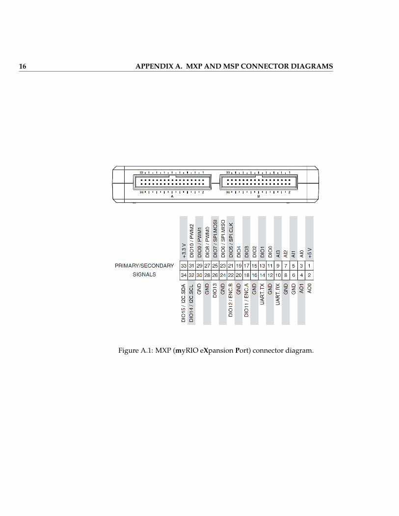
A MXP and MSP Connector Diagrams
16 APPENDIX A. MXP AND MSP CONNECTOR DIAGRAMS
Figure A.1: MXP (myRIO eXpansion Port) connector diagram.
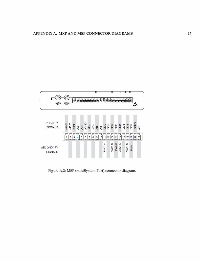
APPENDIX A. MXP AND MSP CONNECTOR DIAGRAMS 17
Figure A.2: MSP (miniSystem Port) connector diagram.

18 APPENDIX A. MXP AND MSP CONNECTOR DIAGRAMS
B Build a Stand-Alone Application
During development you normally connect NI myRIO to your computerwith a USB cable. After development is complete you can easily deployyour project as a stand-alone application stored on the myRIO solid-statehard drive that starts automatically when you power up the myRIO; noUSB cable required. Study the tutorial Deploy a Stand-Alone Application(youtu.be/JXoJECRS-eo, 8:29) to learn the step-by-step procedure to create abuild for the real-time (RT) target, deploy the build as the startup applica-tion, and how to disable the startup application, if necessary.

20 APPENDIX B. BUILD A STAND-ALONE APPLICATION
C Video Tutorial Links