Embed Size (px)
Citation preview
>> Machines / english
h i g h t e c h i s o u r b u s i n e s s .
Precision and High Speed Machines for Milling and Grinding
Röders: Tradition and 200 Years of Innovation
>> www.roeders.de
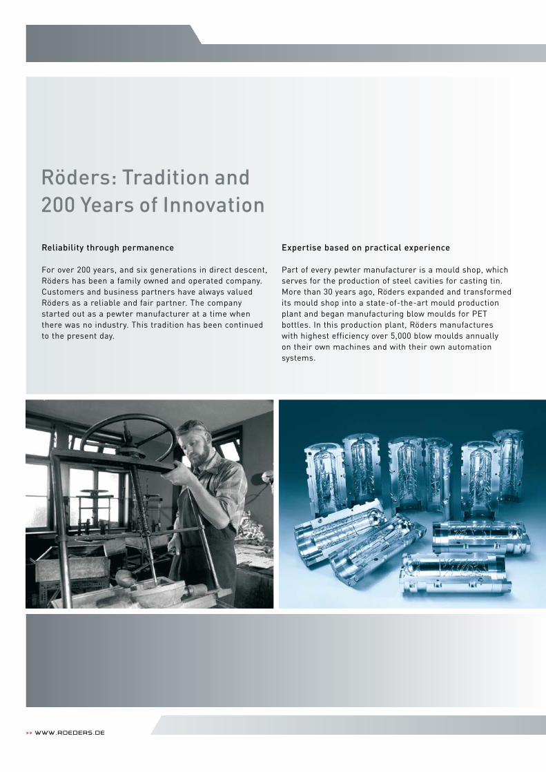
Reliability through permanence
For over 200 years, and six generations in direct descent, Röders has been a family owned and operated company. Customers and business partners have always valued Röders as a reliable and fair partner. The company started out as a pewter manufacturer at a time when there was no industry. This tradition has been continued to the present day.
Expertise based on practical experience
Part of every pewter manufacturer is a mould shop, which serves for the production of steel cavities for casting tin. More than 30 years ago, Röders expanded and transformed its mould shop into a state-of-the-art mould production plant and began manufacturing blow moulds for PET bottles. In this production plant, Röders manufactures with highest efficiency over 5,000 blow moulds annually on their own machines and with their own automation systems.
>> Machinesfor Milling and grinding 2 | 3
h i g h t e c h i s o u r b u s i n e s s .
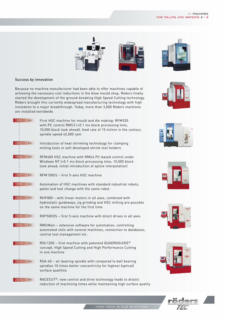
Success by innovation
Because no machine manufacturer had been able to offer machines capable of achieving the necessary cost reductions in the blow mould shop, Röders finally started the development of the ground-breaking High Speed Cutting technology. Röders brought this currently widespread manufacturing technology with high innovation to a major breakthrough. Today, more than 3,000 Röders machines are installed worldwide.
1991 >> First HSC machine for mould and die making: RFM520 with PC control RMS 3 (<0.1 ms block processing time, 10,000 block look ahead), feed rate of 15 m/min in the contour, spindle speed 42,000 rpm
1992 >> Introduction of heat shrinking technology for clamping milling tools in self-developed shrink tool holders
1995 >> RFM600 HSC machine with RMS6 PC-based control under Windows NT (<0.1 ms block processing time, 10,000 block look ahead, initial introduction of spline interpolation)
1997 >> RFM1000 S – first 5-axis HSC machine
1999 >> Automation of HSC machines with standard industrial robots, pallet and tool change with the same robot
2001 >> RHP 800 – with linear motors in all axes, combined with hydrostatic guideways, jig grinding and HSC milling are possible on the same machine for the first time
2005 >> RXP 500 DS – first 5-axis machine with direct drives in all axes
2006 >> RMSMain – extensive software for automation, controlling automated cells with several machines, connection to databases, central tool management etc.
2010 >> RXU 1200 – first machine with patented QUADROGUIDE® concept, High Speed Cutting and High Performance Cutting in one machine
2012 >> RSA-60 – air bearing spindle with compared to ball bearing spindles 10 times better concentricity for highest (optical) surface qualities
2015 >> RACECUT®: new control and drive technology leads to drastic reduction of machining times while maintaining high surface quality
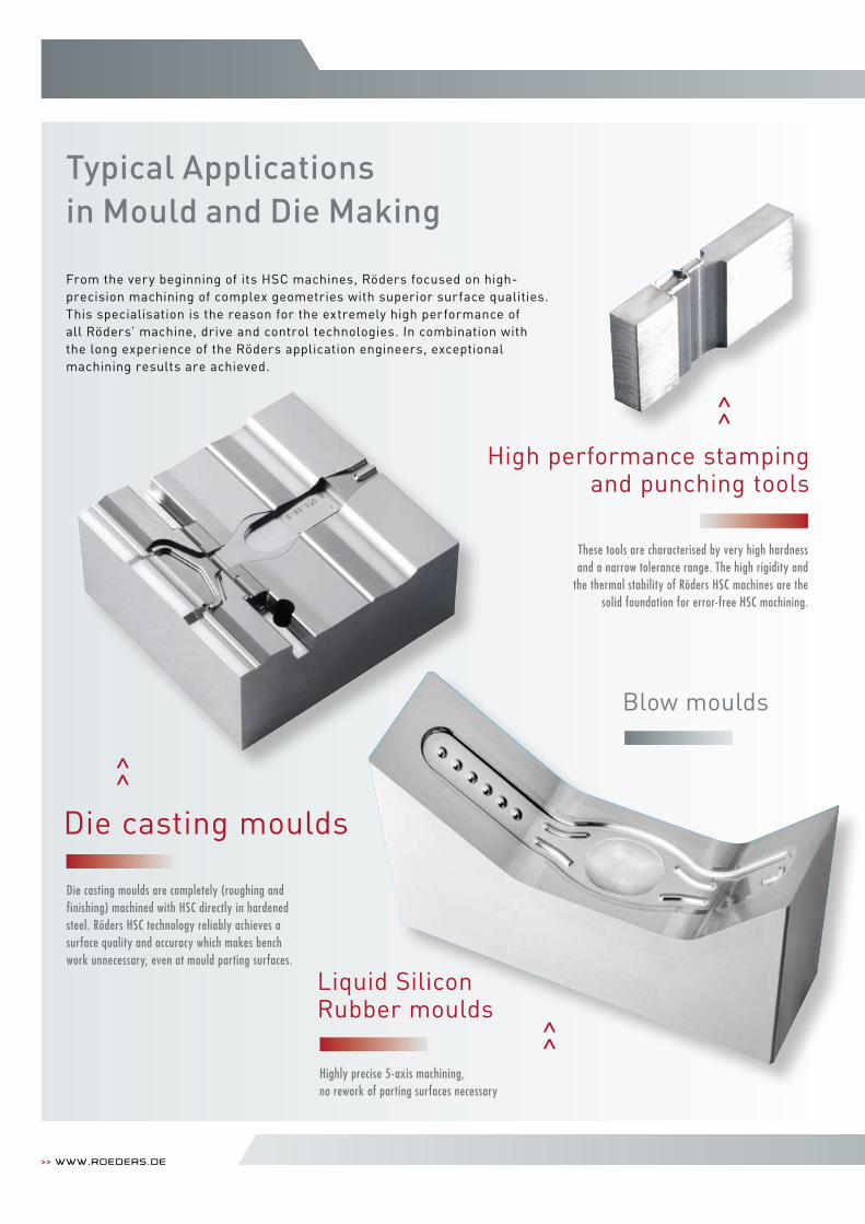
Typical Applications in Mould and Die Making
>> www.roeders.de
Liquid Silicon Rubber moulds <<
>>
>>
These tools are characterised by very high hardness and a narrow tolerance range. The high rigidity and
the thermal stability of Röders HSC machines are the solid foundation for error-free HSC machining.
From the very beginning of its HSC machines, Röders focused on high-precision machining of complex geometries with superior surface qualities. This specialisation is the reason for the extremely high performance of all Röders’ machine, drive and control technologies. In combination with the long experience of the Röders application engineers, exceptional machining results are achieved.
Die casting moulds are completely (roughing and finishing) machined with HSC directly in hardened steel. Röders HSC technology reliably achieves a surface quality and accuracy which makes bench work unnecessary, even at mould parting surfaces.
Highly precise 5-axis machining, no rework of parting surfaces necessary
Die casting moulds
Blow moulds
High performance stamping and punching tools
>> Machinesfor Milling and grinding 4 | 5
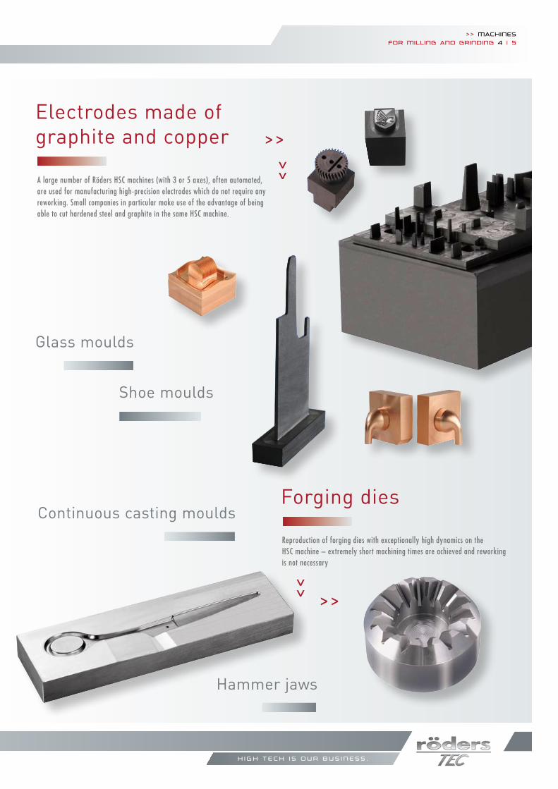
Electrodes made of graphite and copper
>> A large number of Röders HSC machines (with 3 or 5 axes), often automated, are used for manufacturing high-precision electrodes which do not require any reworking. Small companies in particular make use of the advantage of being able to cut hardened steel and graphite in the same HSC machine.
Blow moulds
Forging diesContinuous casting moulds
Glass moulds
Shoe moulds
Hammer jaws
>>
>>
Reproduction of forging dies with exceptionally high dynamics on the HSC machine – extremely short machining times are achieved and reworking is not necessary>>
h i g h t e c h i s o u r b u s i n e s s .
>> www.roeders.de
>>
>>
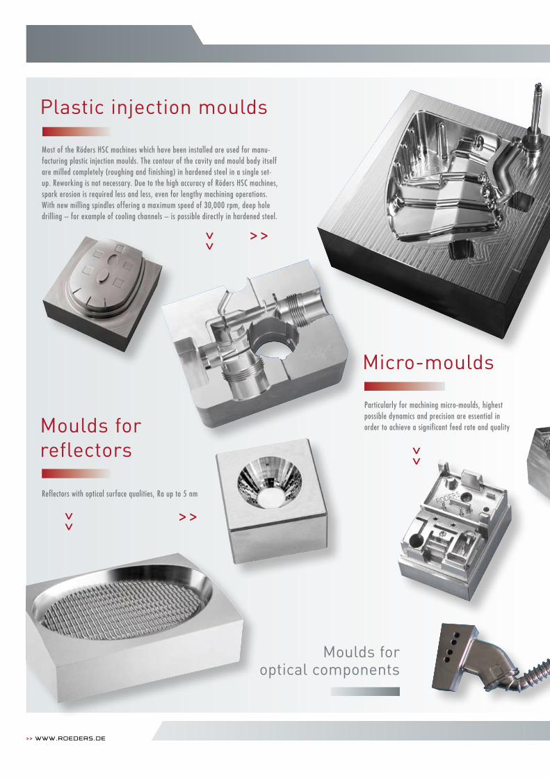
Plastic injection moulds
Micro-moulds
>> Most of the Röders HSC machines which have been installed are used for manu-facturing plastic injection moulds. The contour of the cavity and mould body itself are milled completely (roughing and finishing) in hardened steel in a single set-up. Reworking is not necessary. Due to the high accuracy of Röders HSC machines, spark erosion is required less and less, even for lengthy machining operations. With new milling spindles offering a maximum speed of 30,000 rpm, deep hole drilling – for example of cooling channels – is possible directly in hardened steel.>>
Particularly for machining micro-moulds, highest possible dynamics and precision are essential in order to achieve a significant feed rate and qualityMoulds for
reflectors
Reflectors with optical surface qualities, Ra up to 5 nm
Moulds foroptical components
>>
>> Machinesfor Milling and grinding 6 | 7
<<
<<
>> >>
>>
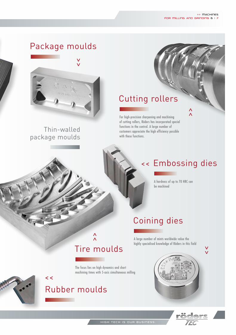
Package moulds
Embossing dies
A hardness of up to 70 HRC can be machined
Coining dies
A large number of mints worldwide value the highly specialised knowledge of Röders in this field
Cutting rollers
Thin-walled package moulds
<<
Tire moulds
The focus lies on high dynamics and short machining times with 5-axis simultaneous milling
For high-precision sharpening and machining of cutting rollers, Röders has incorporated special functions in the control. A large number of customers appreciate the high efficiency possible with these functions.
h i g h t e c h i s o u r b u s i n e s s .
Rubber moulds
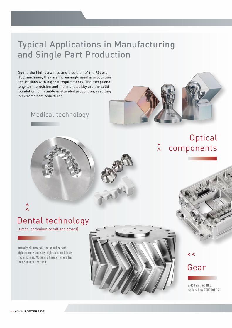
Typical Applications in Manufacturing and Single Part Production
>> www.roeders.de
Due to the high dynamics and precision of the Röders HSC machines, they are increasingly used in production applications with highest requirements. The exceptional long-term precision and thermal stability are the solid foundation for reliable unattended production, resulting in extreme cost reductions.
>>
>>
Dental technology (zircon, chromium cobalt and others)
Virtually all materials can be milled with high accuracy and very high speed on Röders HSC machines. Machining times often are less than 5 minutes per unit.
Medical technology
Opticalcomponents
Gear
Ø 450 mm, 60 HRC, machined on RXU 1001 DSH
<<
>> Machinesfor Milling and grinding 8 | 9
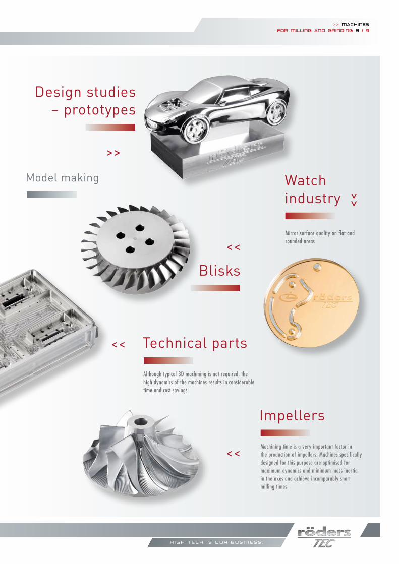
Model making
Impellers
Design studies – prototypes
<<
<<
>>
Machining time is a very important factor in the production of impellers. Machines specifically designed for this purpose are optimised for maximum dynamics and minimum mass inertia in the axes and achieve incomparably short milling times.
<<
Blisks
Technical parts
>>
Although typical 3D machining is not required, the high dynamics of the machines results in considerable time and cost savings.
Mirror surface quality on flat and rounded areas
Watch industry
h i g h t e c h i s o u r b u s i n e s s .
Ø 450 mm, 60 HRC, machined on RXU 1001 DSH
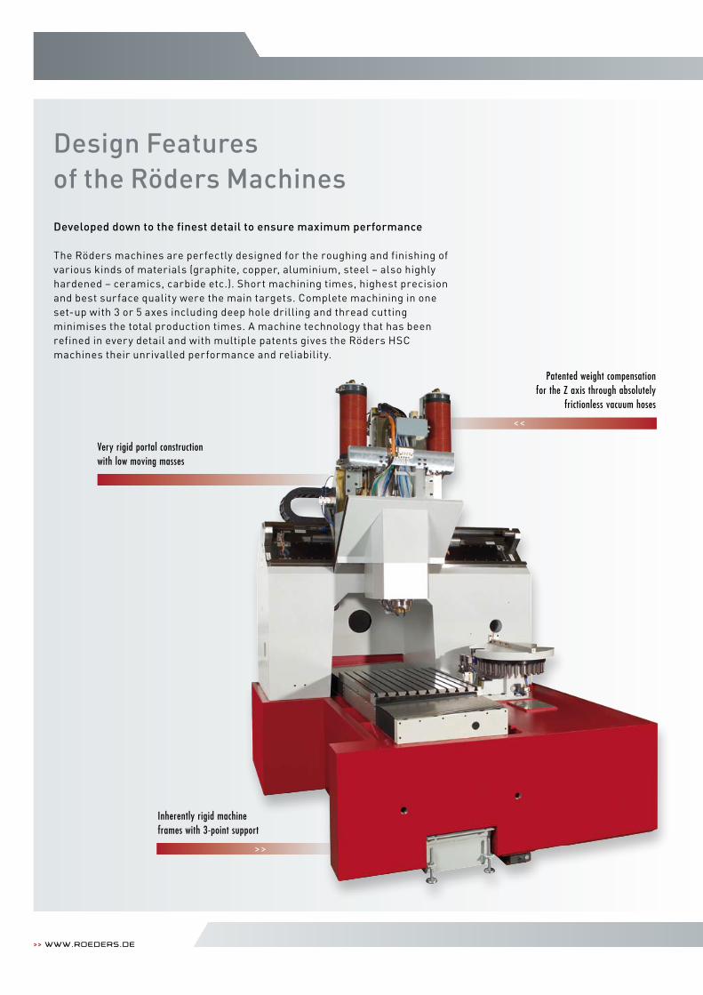
Design Features of the Röders Machines
>> www.roeders.de
<<
>>
Patented weight compensation for the Z axis through absolutely
frictionless vacuum hoses
Very rigid portal construction with low moving masses
Inherently rigid machine frames with 3-point support
Developed down to the finest detail to ensure maximum performance
The Röders machines are perfectly designed for the roughing and finishing of various kinds of materials (graphite, copper, aluminium, steel – also highly hardened – ceramics, carbide etc.). Short machining times, highest precision and best surface quality were the main targets. Complete machining in one set-up with 3 or 5 axes including deep hole drilling and thread cutting minimises the total production times. A machine technology that has been refined in every detail and with multiple patents gives the Röders HSC machines their unrivalled performance and reliability.
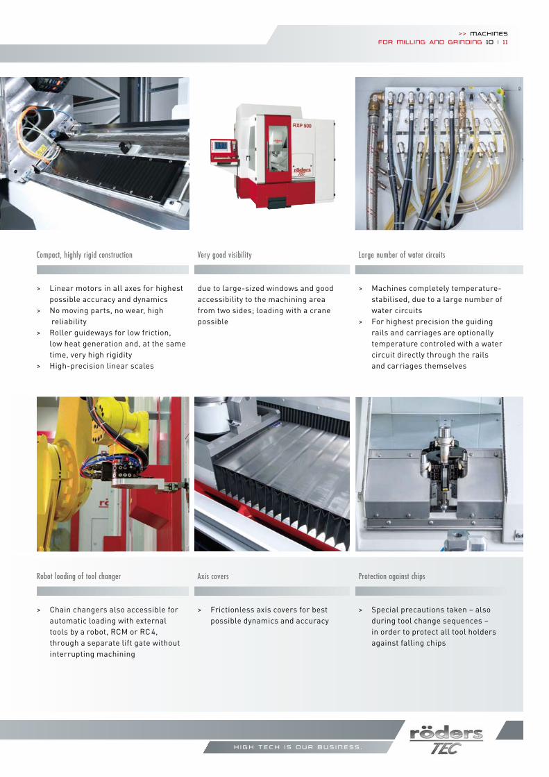
Very good visibility
due to large-sized windows and good accessibility to the machining area from two sides; loading with a crane possible
Robot loading of tool changer
> Chain changers also accessible for automatic loading with external tools by a robot, RCM or RC 4, through a separate lift gate without interrupting machining
Large number of water circuits
> Machines completely temperature-stabilised, due to a large number of water circuits
> For highest precision the guiding rails and carriages are optionally temperature controled with a water circuit directly through the rails and carriages themselves
Protection against chips
> Special precautions taken – also during tool change sequences – in order to protect all tool holders against falling chips
Axis covers
> Frictionless axis covers for best possible dynamics and accuracy
>> Machinesfor Milling and grinding 10 | 11
h i g h t e c h i s o u r b u s i n e s s .
Compact, highly rigid construction
> Linear motors in all axes for highest possible accuracy and dynamics
> No moving parts, no wear, high reliability
> Roller guideways for low friction, low heat generation and, at the same time, very high rigidity
> High-precision linear scales
>> www.roeders.de
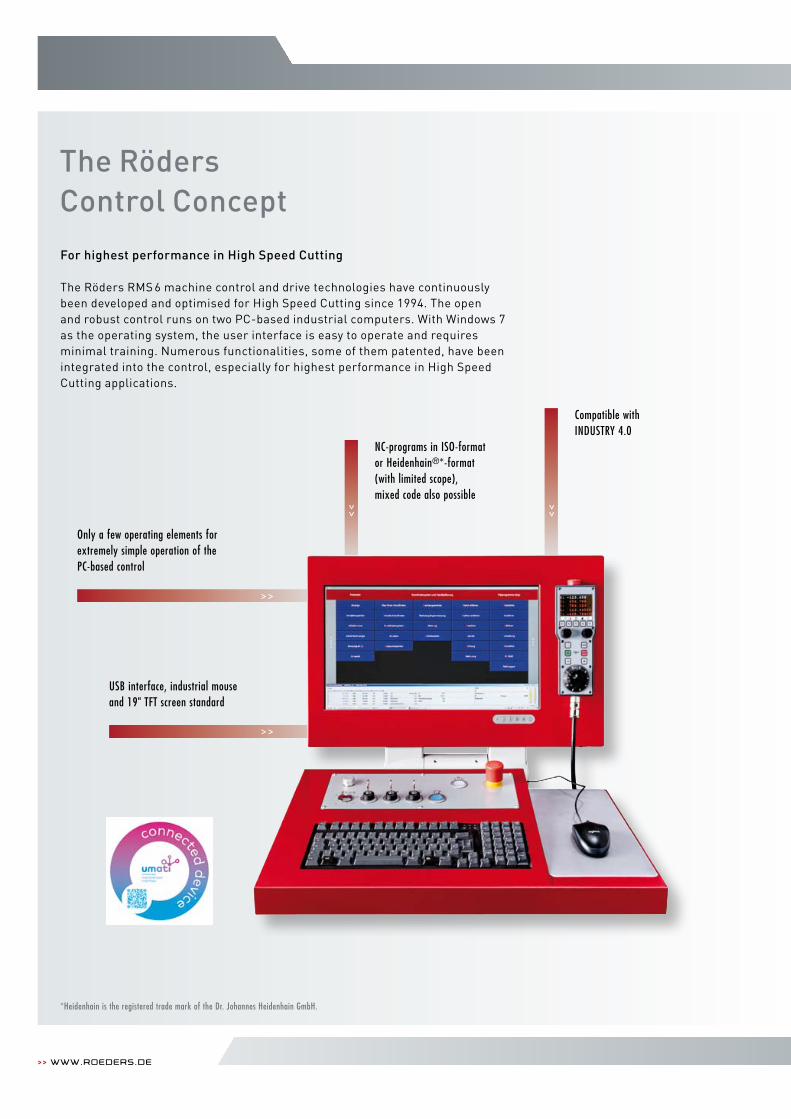
The Röders Control Concept
Only a few operating elements for extremely simple operation of the PC-based control
For highest performance in High Speed Cutting
The Röders RMS 6 machine control and drive technologies have continuously been developed and optimised for High Speed Cutting since 1994. The open and robust control runs on two PC-based industrial computers. With Windows 7 as the operating system, the user interface is easy to operate and requires minimal training. Numerous functionalities, some of them patented, have been integrated into the control, especially for highest performance in High Speed Cutting applications.
NC-programs in ISO-formator Heidenhain®*-format(with limited scope),mixed code also possible
Compatible withINDUSTRY 4.0
*Heidenhain is the registered trade mark of the Dr. Johannes Heidenhain GmbH.
USB interface, industrial mouse and 19" TFT screen standard
>> Machinesfor Milling and grinding 12 | 13
h i g h t e c h i s o u r b u s i n e s s .
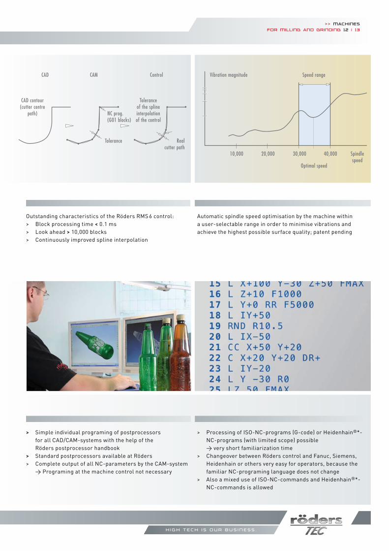
Speed range
Optimal speed
10,000 20,000 30,000 40,000 Spindle speed
Vibration magnitude CAD
CAD contour(cutter centre
path)
Tolerance
NC prog.(G01 blocks)
Tolerance of the splineinter polation of the control
Real cutter path
CAM Control
Outstanding characteristics of the Röders RMS 6 control: > Block processing time < 0.1 ms> Look ahead > 10,000 blocks> Continuously improved spline interpolation
Automatic spindle speed optimisation by the machine within a user-selectable range in order to minimise vibrations and achieve the highest possible surface quality; patent pending
> Simple individual programing of postprocessors for all CAD/CAM-systems with the help of the Röders postprocessor handbook> Standard postprocessors available at Röders> Complete output of all NC-parameters by the CAM-system → Programing at the machine control not necessary
> Processing of ISO-NC-programs (G-code) or Heidenhain®*- NC-programs (with limited scope) possible → very short familiarization time> Changeover between Röders control and Fanuc, Siemens, Heidenhain or others very easy for operators, because the familiar NC-programing language does not change> Also a mixed use of ISO-NC-commands and Heidenhain®*- NC-commands is allowed
>> www.roeders.de
Patented function to avoid offsets in transitional areas if several different tools are used for machining > Automatic modification of the machining programs for tangential transitions
Tool 2
Original programs
Modified programs
Tool 1
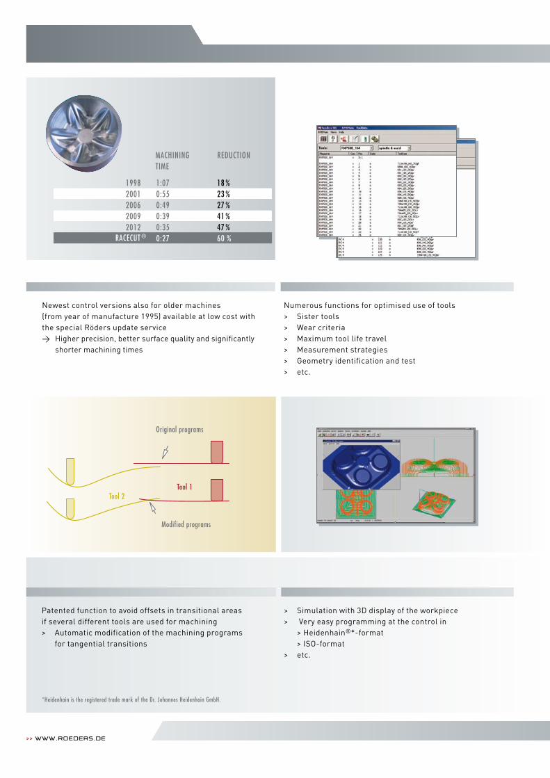
Numerous functions for optimised use of tools> Sister tools> Wear criteria> Maximum tool life travel> Measurement strategies > Geometry identification and test> etc.
Newest control versions also for older machines (from year of manufacture 1995) available at low cost with the special Röders update service→ Higher precision, better surface quality and significantly shorter machining times
MACHININGTIMe
ReDUCTION
19982001200620092012
1:070:550:490:390:350:27
18 %23 %27 %41 %47 %60 %RACeCUT ®
> Simulation with 3D display of the workpiece> Very easy programming at the control in > Heidenhain®*-format > ISO-format> etc.
*Heidenhain is the registered trade mark of the Dr. Johannes Heidenhain GmbH.
>> Machinesfor Milling and grinding 14 | 15
h i g h t e c h i s o u r b u s i n e s s .
Röders’ own Drive Technology
High precision by shortest cycle times
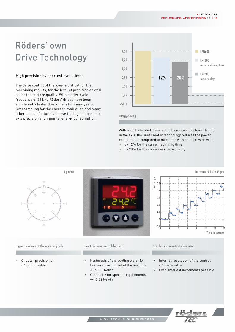
The drive control of the axes is critical for themachining results, for the level of precision as wellas for the surface quality. With a drive cyclefrequency of 32 kHz Röders’ drives have beensignificantly faster than others for many years. Oversampling for the encoder evaluation and many other special features achieve the highest possible axis precision and minimal energy consumption.
Highest precision of the machining path
> Circular precision of < 1 µm possible
1 µm/div
Smallest increments of movement
> Internal resolution of the control < 1 nanometre> Even smallest increments possible
Time in seconds
exact temperature stabilisation
> Hysteresis of the cooling water for temperature control of the machine
< +/- 0.1 Kelvin > Optionally for special requirements +/- 0.02 Kelvin
energy-saving
With a sophisticated drive technology as well as lower friction in the axis, the linear motor technology reduces the power consumption compared to machines with ball screw drives:> by 12 % for the same machining time> by 20 % for the same workpiece quality
RFM600
RXP500same machining time
RXP500same quality-12 % -20 %
1,50
1,00
1,25
0,75
0,50
0,25
kWh 0
Increment 0.1 / 0.05 µm
Trav
el in
µm
>> www.roeders.de
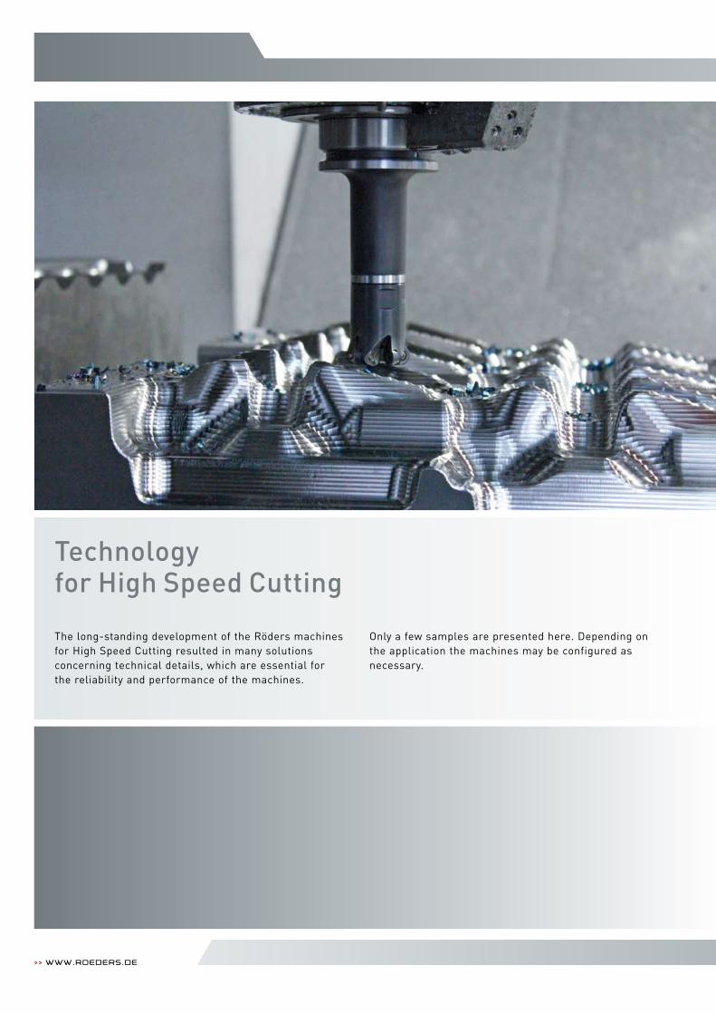
The long-standing development of the Röders machines for High Speed Cutting resulted in many solutions concerning technical details, which are essential for the reliability and performance of the machines.
Only a few samples are presented here. Depending on the application the machines may be configured as necessary.
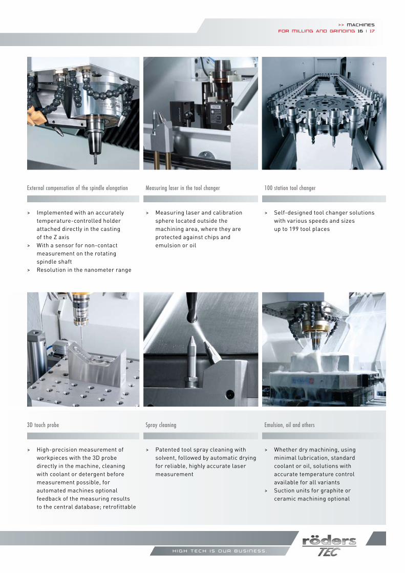
Technology for High Speed Cutting
>> Machinesfor Milling and grinding 16 | 17
h i g h t e c h i s o u r b u s i n e s s .
emulsion, oil and others
> Whether dry machining, using mini mal lubrication, standard coolant or oil, solutions with accurate temperature control available for all variants
> Suction units for graphite or ceramic machining optional
Measuring laser in the tool changer
> Measuring laser and calibration sphere located outside the machining area, where they are protected against chips and emulsion or oil
Spray cleaning
> Patented tool spray cleaning with solvent, followed by automatic drying for reliable, highly accurate laser measurement
100 station tool changer
> Self-designed tool changer solutions with various speeds and sizes up to 199 tool places
external compensation of the spindle elongation
> Implemented with an accurately temperature-controlled holder attached directly in the casting of the Z axis> With a sensor for non-contact measurement on the rotating spindle shaft> Resolution in the nanometer range
3D touch probe
> High-precision measurement of workpieces with the 3D probe directly in the machine, cleaning with coolant or detergent before measurement possible, for automated machines optional feedback of the measuring results to the central database; retrofittable
>> www.roeders.de
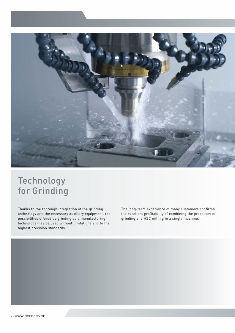
Thanks to the thorough integration of the grinding technology and the necessary auxiliary equipment, the possibilities offered by grinding as a manufacturing technology may be used without limitations and to the highest precision standards.
The long-term experience of many customers confirms the excellent profitability of combining the processes of grinding and HSC milling in a single machine.
Technology for Grinding
h i g h t e c h i s o u r b u s i n e s s .
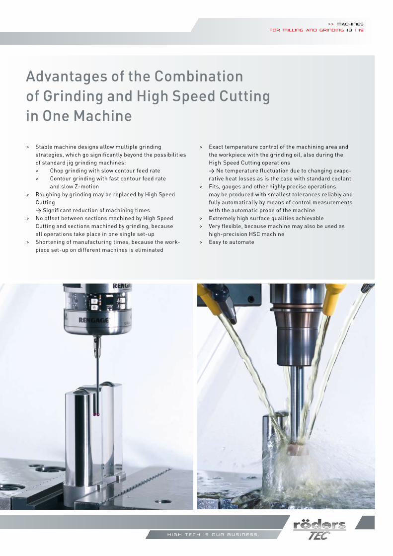
Advantages of the Combination of Grinding and High Speed Cutting in One Machine
> Stable machine designs allow multiple grinding strategies, which go significantly beyond the possibilities of standard jig grinding machines: > Chop grinding with slow contour feed rate > Contour grinding with fast contour feed rate and slow Z-motion> Roughing by grinding may be replaced by High Speed Cutting → Significant reduction of machining times> No offset between sections machined by High Speed Cutting and sections machined by grinding, because all operations take place in one single set-up> Shortening of manufacturing times, because the work- piece set-up on different machines is eliminated
> Exact temperature control of the machining area and the workpiece with the grinding oil, also during the High Speed Cutting operations → No temperature fluctuation due to changing evapo- rative heat losses as is the case with standard coolant> Fits, gauges and other highly precise operations may be produced with smallest tolerances reliably and fully automatically by means of control measurements with the automatic probe of the machine > Extremely high surface qualities achievable> Very flexible, because machine may also be used as high-precision HSC machine> Easy to automate
>> Machinesfor Milling and grinding 18 | 19
>> www.roeders.de
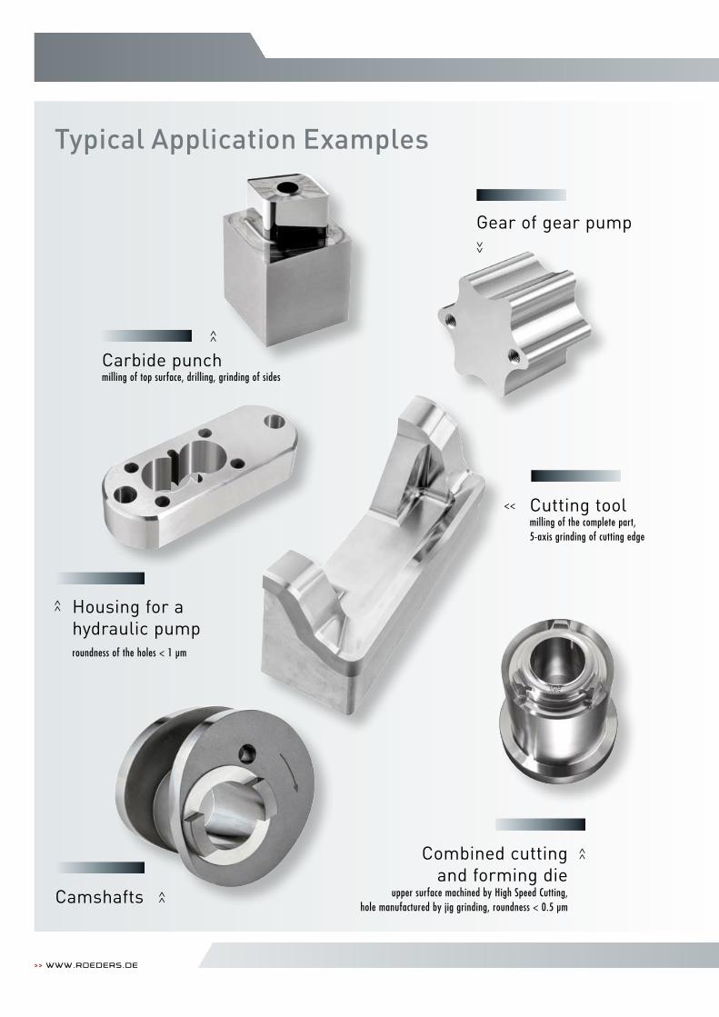
Typical Application Examples
Carbide punch milling of top surface, drilling, grinding of sides
Cutting tool milling of the complete part, 5-axis grinding of cutting edge
Housing for a hydraulic pump roundness of the holes < 1 µm
Camshafts
Gear of gear pump
>>
<<
>>
>>
>>
>> Combined cuttingand forming die
upper surface machined by High Speed Cutting, hole manufactured by jig grinding, roundness < 0.5 µm
h i g h t e c h i s o u r b u s i n e s s .
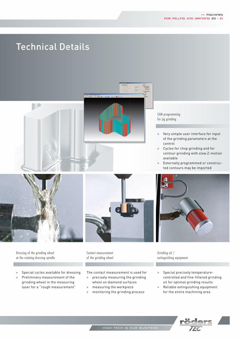
Technical Details
Contact measurement of the grinding wheel
The contact measurement is used for> precisely measuring the grinding wheel on diamond surfaces> measuring the workpiece> monitoring the grinding process
Grinding oil / extinguishing equipment
> Special precisely temperature- controlled and fine-filtered grinding oil for optimal grinding results> Reliable extinguishing equipment for the entire machining area
Dressing of the grinding wheel at the rotating dressing spindle
> Special cycles available for dressing> Preliminary measurement of the grinding wheel in the measuring laser for a “rough measurement”
CAM programming for jig grinding
> Very simple user interface for input of the grinding parameters at the control> Cycles for chop grinding and for contour grinding with slow Z-motion available> Externally programmed or construc- ted contours may be imported
>> Machinesfor Milling and grinding 20 | 21
>> www.roeders.de
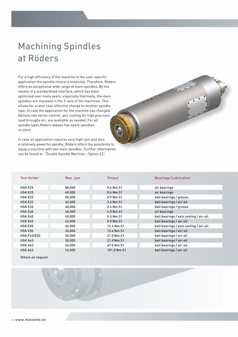
Machining Spindles at Röders
For a high efficiency of the machine in the user-specificapplication the spindle choice is essential. Therefore, Rödersoffers an exceptional wide range of main spindles. By themeans of a standardized interface, which has beenoptimized over many years, especially thermally, the mainspindles are mounted in the Z-axis of the machines. This allows for a later cost-effective change to another spindle type, in case the application for the machine has changed. Options like vector control, axis cooling for high precision, lead throughs etc. are available as needed. For allspindle types Röders always has spare spindlesin stock.
In case an application requires very high rpm and alsoa relatively powerful spindle, Röders offers the possibility to equip a machine with two main spindles. Further information can be found at: “Double Spindle Machine – Option Z2”.
Tool Holder
HSK E25HSK E25HSK E25HSK E32HSK E32HSK E40HSK E40HSK E40HSK E50HSK E50HSK F63/E50HSK A63HSK A63HSK A63
Others on request.
Torque
0.6 Nm S10.6 Nm S10.9 Nm S13.4 Nm S12.4 Nm S14.0 Nm S15.5 Nm S15.9 Nm S112.4 Nm S112.4 Nm S121.0 Nm S121.0 Nm S167.0 Nm S1101.0 Nm S1
Bearings / Lubrication
air bearingsair bearingsball bearings / greaseball bearings / air-oilball bearings / greaseair bearingsball bearings / axis cooling / air-oilball bearings / air-oilball bearings / axis cooling / air-oilball bearings / air-oilball bearings / air-oilball bearings / air-oilball bearings / air-oilball bearings / air-oil
Max. rpm
80,00060,00050,00060,00040,00060,00045,00042,00036,00036,00030,00030,00024,00022,000
>> Machinesfor Milling and grinding 22 | 23
h i g h t e c h i s o u r b u s i n e s s .
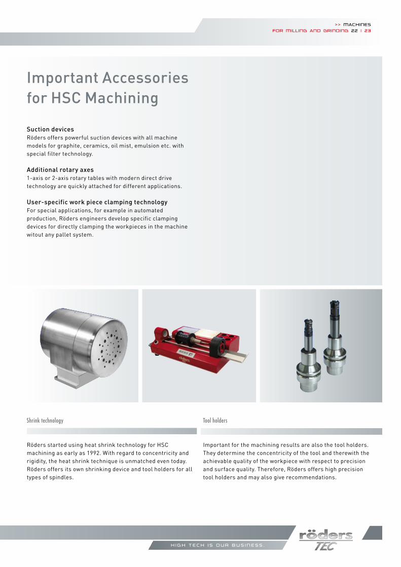
Important Accessories for HSC Machining
Shrink technology
Röders started using heat shrink technology for HSC machining as early as 1992. With regard to concentricity and rigidity, the heat shrink technique is unmatched even today. Röders offers its own shrinking device and tool holders for all types of spindles.
Tool holders
Important for the machining results are also the tool holders. They determine the concentricity of the tool and therewith the achievable quality of the workpiece with respect to precision and surface quality. Therefore, Röders offers high precision tool holders and may also give recommendations.
Suction devicesRöders offers powerful suction devices with all machine models for graphite, ceramics, oil mist, emulsion etc. with special filter technology.
Additional rotary axes1-axis or 2-axis rotary tables with modern direct drive technology are quickly attached for different applications.
User-specific work piece clamping technologyFor special applications, for example in automated production, Röders engineers develop specific clamping devices for directly clamping the workpieces in the machine witout any pallet system.
>> www.roeders.de
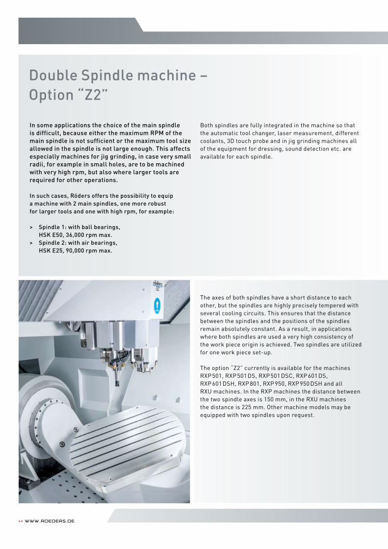
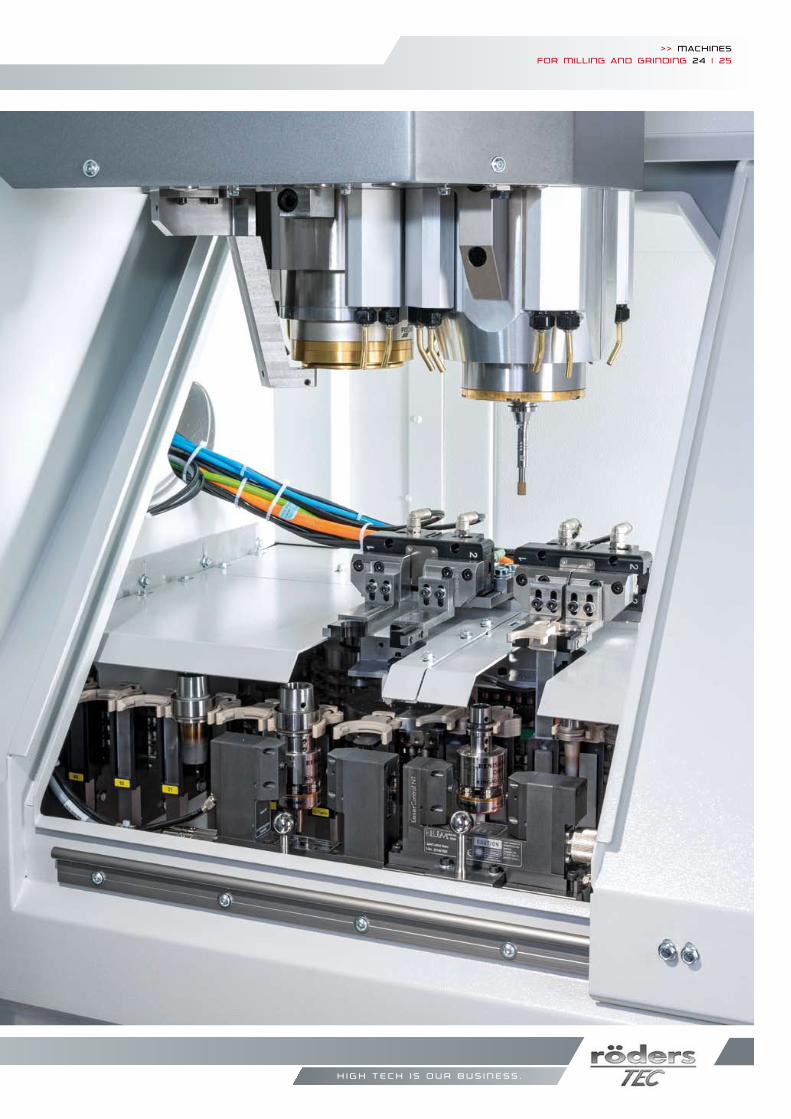
Double Spindle machine – Option “Z2”
The axes of both spindles have a short distance to each other, but the spindles are highly precisely tempered with several cooling circuits. This ensures that the distance between the spindles and the positions of the spindles remain absolutely constant. As a result, in applications where both spindles are used a very high consistency of the work piece origin is achieved. Two spindles are utilized for one work piece set-up. The option “Z2” currently is available for the machines RXP 501, RXP 501 DS, RXP 501 DSC, RXP 601 DS, RXP 601 DSH, RXP 801, RXP 950, RXP 950 DSH and all RXU machines. In the RXP machines the distance between the two spindle axes is 150 mm, in the RXU machines the distance is 225 mm. Other machine models may be equipped with two spindles upon request.
In some applications the choice of the main spindle is difficult, because either the maximum RPM of the main spindle is not sufficient or the maximum tool size allowed in the spindle is not large enough. This affects especially machines for jig grinding, in case very small radii, for example in small holes, are to be machined with very high rpm, but also where larger tools are required for other operations. In such cases, Röders offers the possibility to equip a machine with 2 main spindles, one more robust for larger tools and one with high rpm, for example:
> Spindle 1: with ball bearings, HSK E50, 36,000 rpm max.> Spindle 2: with air bearings, HSK E25, 90,000 rpm max.
Both spindles are fully integrated in the machine so that the automatic tool changer, laser measurement, different coolants, 3D touch probe and in jig grinding machines all of the equipment for dressing, sound detection etc. are available for each spindle.
>> Machinesfor Milling and grinding 24 | 25
h i g h t e c h i s o u r b u s i n e s s .
Service – More Than Just Machines
>> www.roeders.de
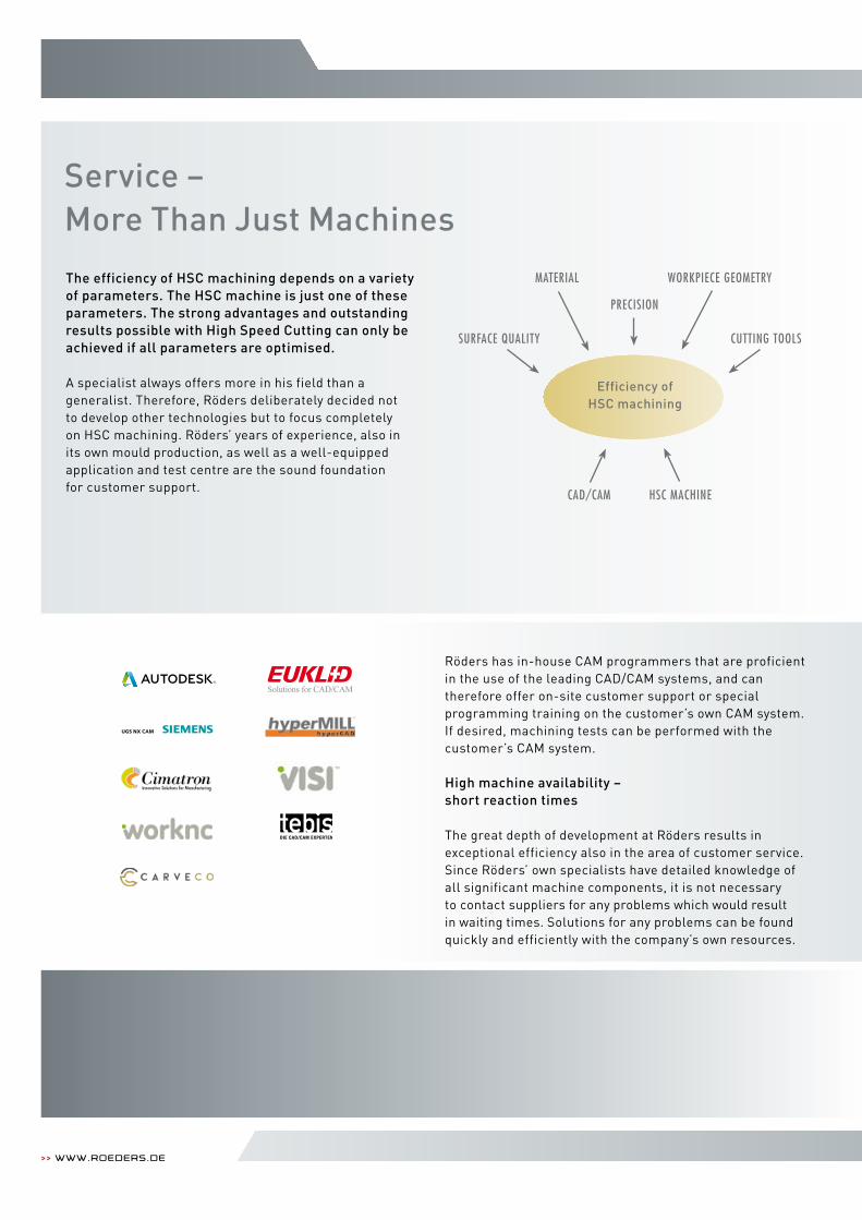
The efficiency of HSC machining depends on a variety of parameters. The HSC machine is just one of these parameters. The strong advantages and outstanding results possible with High Speed Cutting can only be achieved if all parameters are optimised.
A specialist always offers more in his field than a generalist. Therefore, Röders deliberately decided not to develop other technologies but to focus completely on HSC machining. Röders’ years of experience, also in its own mould production, as well as a well-equipped application and test centre are the sound foundation for customer support.
Efficiency of HSC machining
MATeRIAL WORkPIeCe GeOMeTRY
PReCISION
SURFACe QUALITY CUTTING TOOLS
CAD/CAM HSC MACHINe
Röders has in-house CAM programmers that are proficient in the use of the leading CAD/CAM systems, and can therefore offer on-site customer support or special program ming training on the customer’s own CAM system. If desired, machining tests can be performed with the customer’s CAM system.
High machine availability – short reaction times
The great depth of development at Röders results in exceptional efficiency also in the area of customer service. Since Röders’ own specialists have detailed knowledge of all significant machine components, it is not necessary to contact suppliers for any problems which would result in waiting times. Solutions for any problems can be found quickly and efficiently with the company’s own resources.
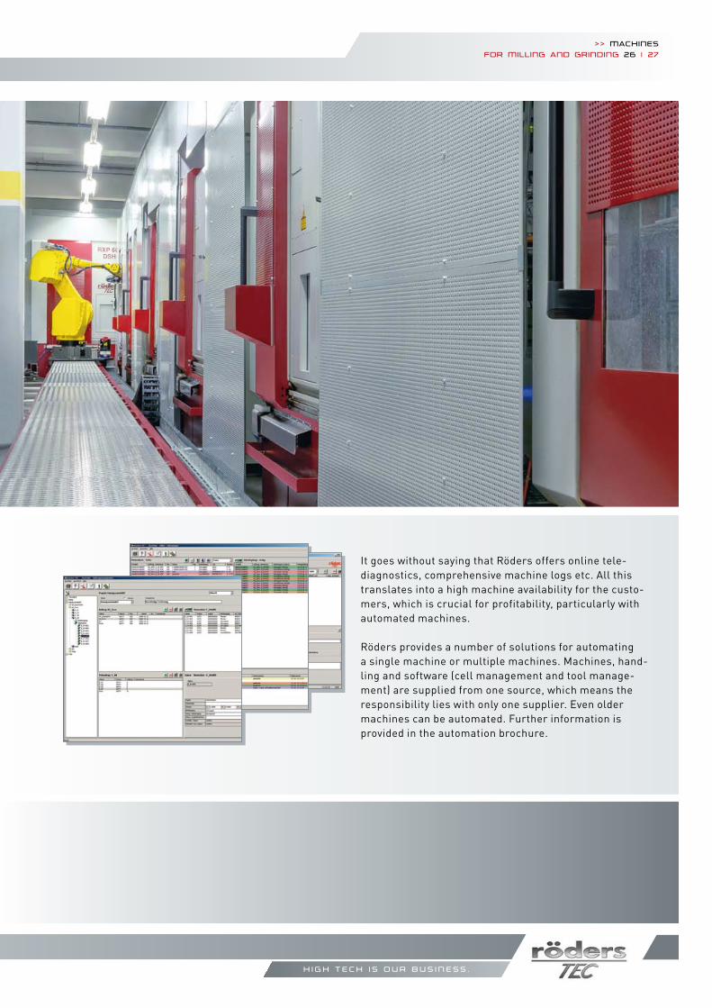
It goes without saying that Röders offers online tele-diagnostics, comprehensive machine logs etc. All this trans lates into a high machine availability for the custo-mers, which is crucial for profitability, particularly with automated machines.
Röders provides a number of solutions for automating a single machine or multiple machines. Machines, hand-ling and software (cell management and tool manage-ment) are supplied from one source, which means the responsibility lies with only one supplier. Even older machines can be automated. Further information is provided in the automation brochure.
h i g h t e c h i s o u r b u s i n e s s .
>> Machinesfor Milling and grinding 26 | 27
>> www.roeders.de
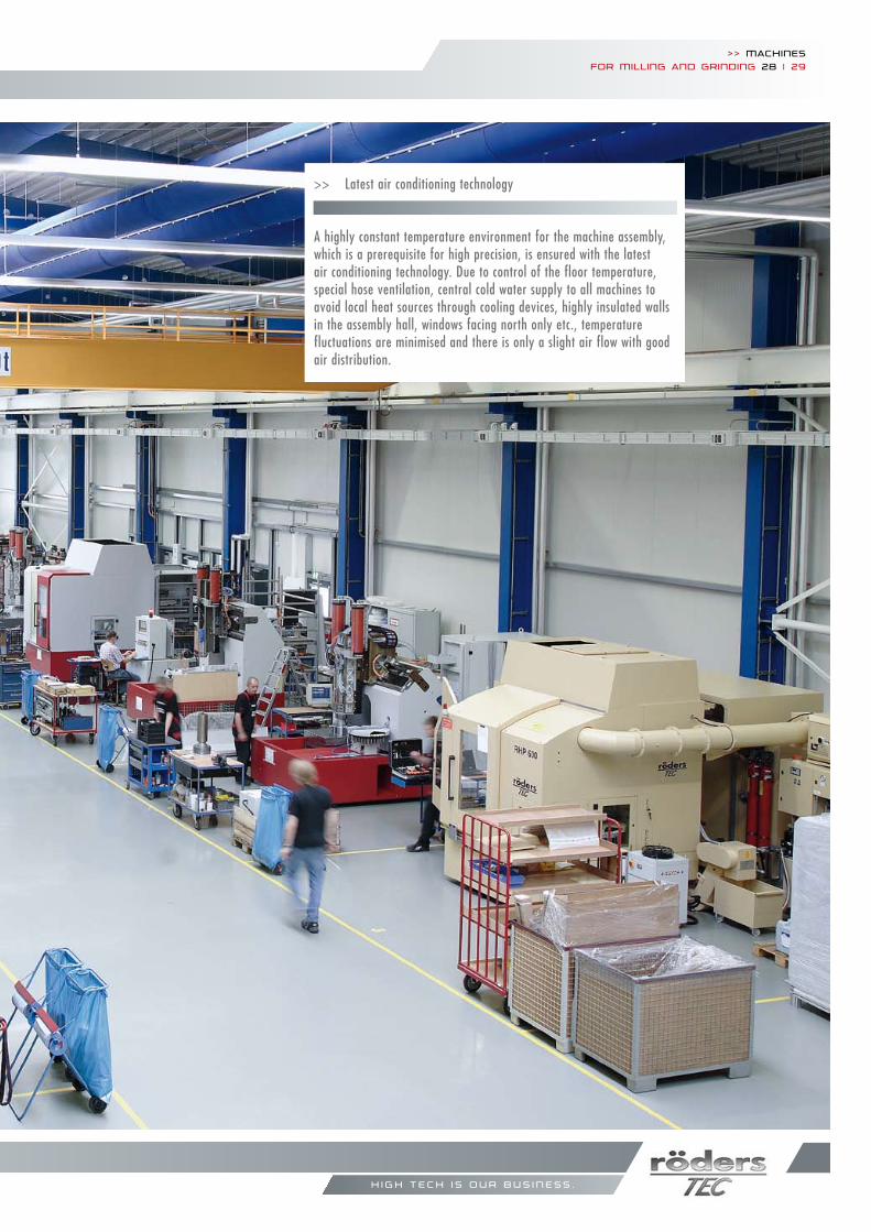
>> Latest air conditioning technology
A highly constant temperature environment for the machine assembly, which is a prerequisite for high precision, is ensured with the latest air conditioning technology. Due to control of the floor temperature, special hose ventilation, central cold water supply to all machines to avoid local heat sources through cooling devices, highly insulated walls in the assembly hall, windows facing north only etc., temperature fluctuations are mini mised and there is only a slight air flow with good air distribution.
h i g h t e c h i s o u r b u s i n e s s .
>> Machinesfor Milling and grinding 28 | 29
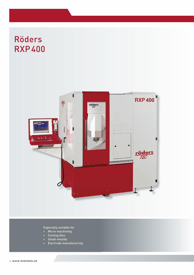
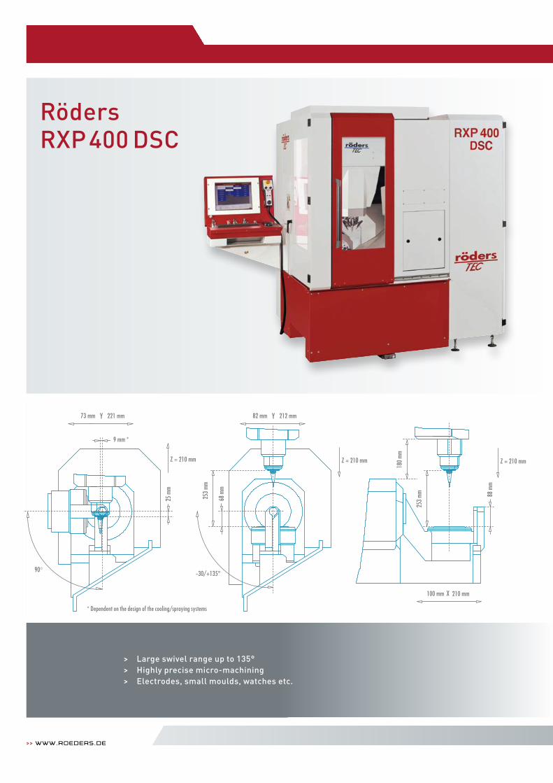
RödersRXP400
>> www.roeders.de
Especially suitable for> Micro-machining > Coining dies> Small moulds > Electrode manufacturing
>> Machinesfor Milling and grinding 30 | 31
Machining range
Table dimensions
Maximum height
Workpiece weight
Feed
Milling spindle (standard)
Tool changer
Chip disposal
Machine weight
Required space
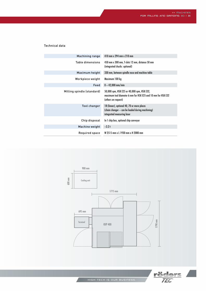
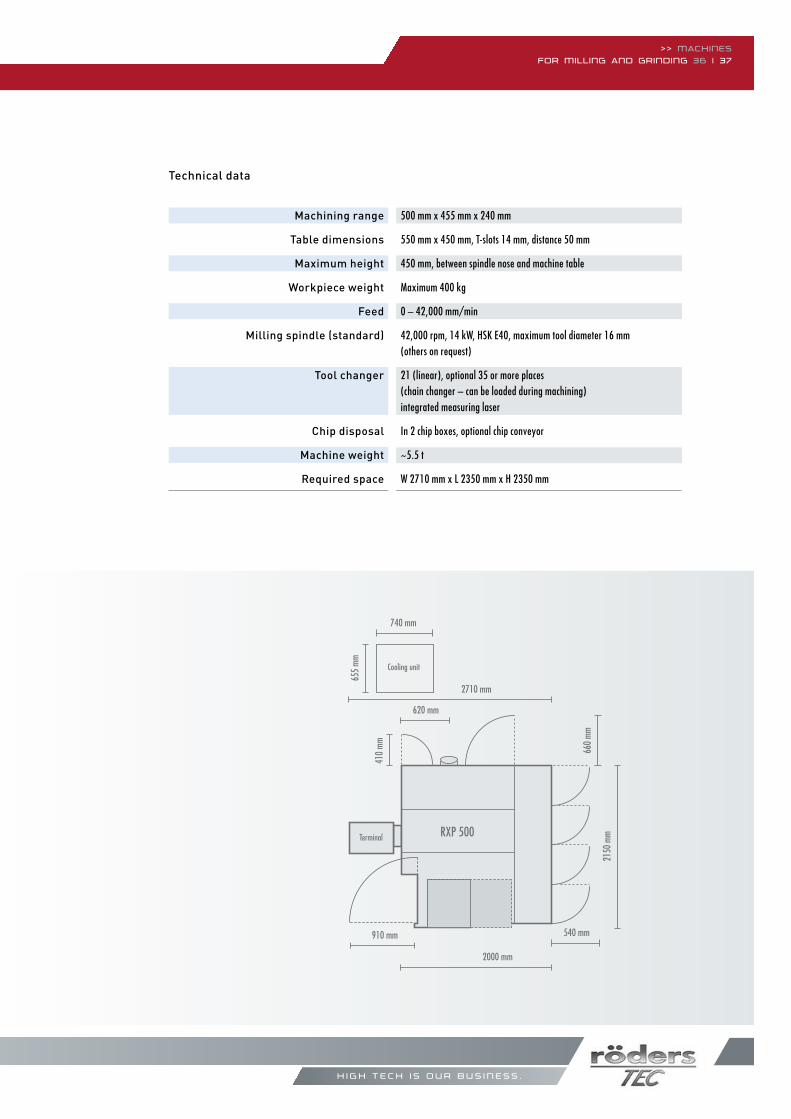
Technical data
h i g h t e c h i s o u r b u s i n e s s .
410 mm x 294 mm x 210 mm
450 mm x 300 mm, T-slots 12 mm, distance 50 mm(integrated chucks optional)
330 mm, between spindle nose and machine table
Maximum 100 kg
0 – 42,000 mm/min
50,000 rpm, HSk e25 or 40,000 rpm, HSk e32,maximum tool diameter 6 mm for HSk e25 and 10 mm for HSk e32(others on request)
18 (linear), optional 40, 70 or more places (chain changer – can be loaded during machining) integrated measuring laser
In 1 chip box, optional chip conveyor
~3.2 t
W 2515 mm x L 1930 mm x H 2080 mm
600
mm Cooling unit
695 mm
1775 mm
1790
mm
900 mm
RXP 400Terminal
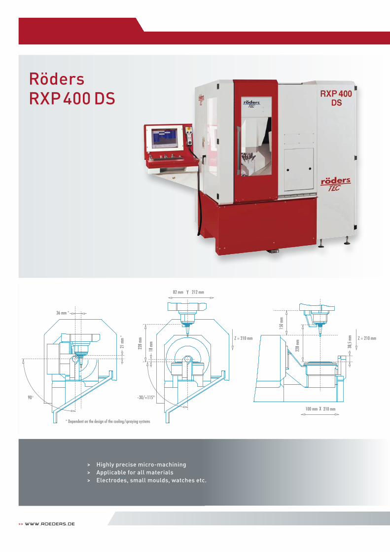
RödersRXP400 DS
>> www.roeders.de
> Highly precise micro-machining > Applicable for all materials> Electrodes, small moulds, watches etc.
* Dependent on the design of the cooling/spraying systems
82 mm Y 212 mm
Z = 210 mm Z = 210 mm
228
mm
228
mm
21 m
m *
38,5
mm
18 m
m
36 mm *
RXP 400 DS
150
mm
100 mm X 210 mm
90° -30/+115°
82 mm Y 212 mm
Z = 210 mm Z = 210 mm
228
mm
228
mm
21 m
m *
38,5
mm
18 m
m
36 mm *
RXP 400 DS
150
mm
100 mm X 210 mm
90° -30/+115°
82 mm Y 212 mm
Z = 210 mm Z = 210 mm
228
mm
228
mm
21 m
m *
38,5
mm
18 m
m
36 mm *
RXP 400 DS
150
mm
100 mm X 210 mm
90° -30/+115°
>> Machinesfor Milling and grinding 32 | 33
h i g h t e c h i s o u r b u s i n e s s .
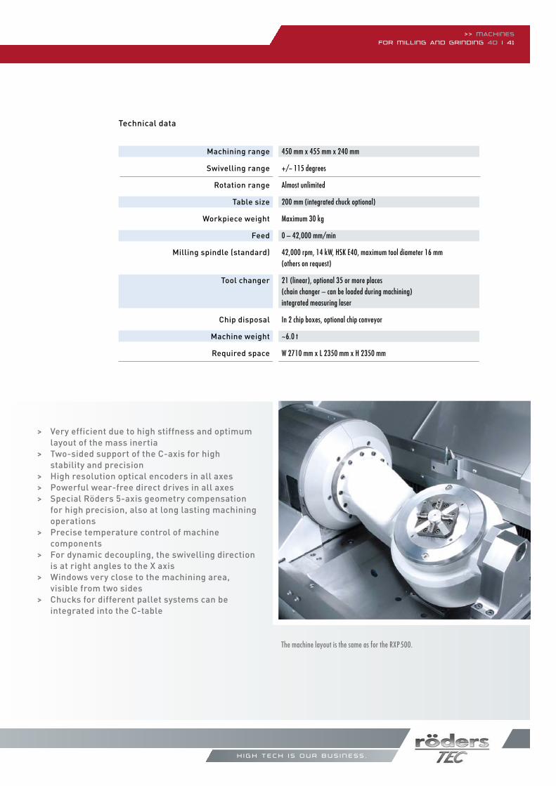
Machining range
Swivelling range
Rotation range
Table size
Workpiece weight
Feed
Milling spindle (standard)
Tool changer
Chip disposal
Machine weight
Required space
Technical data
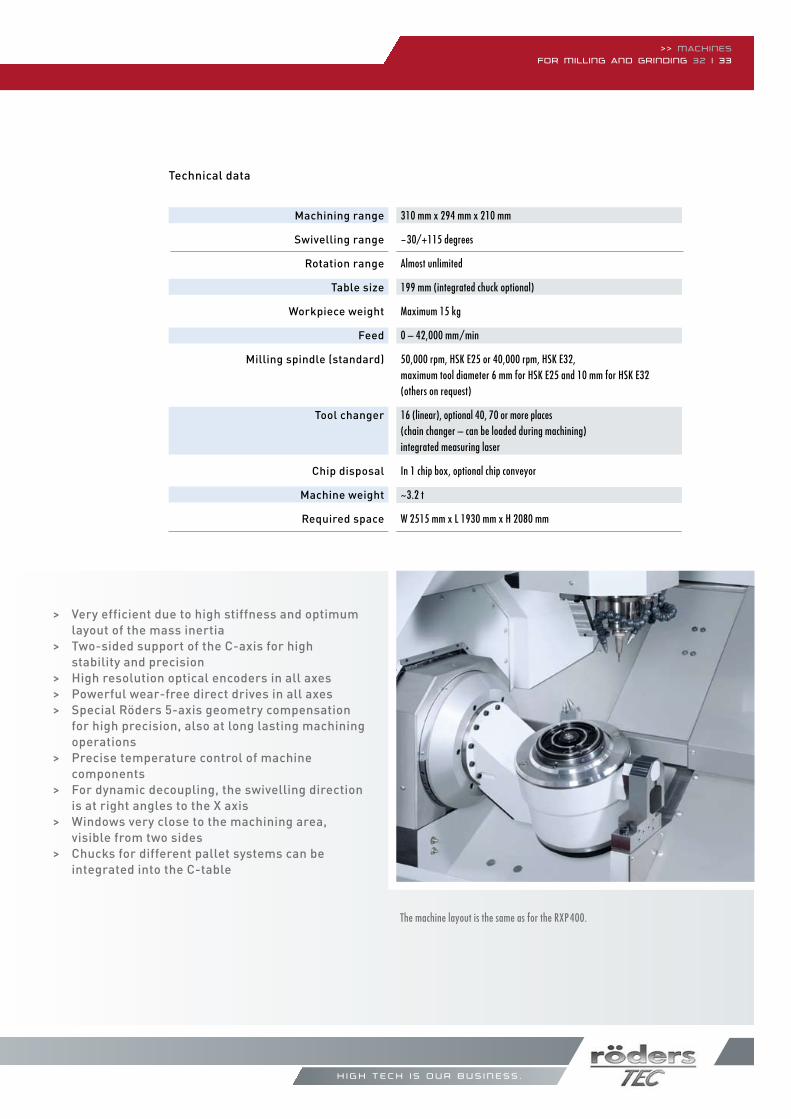
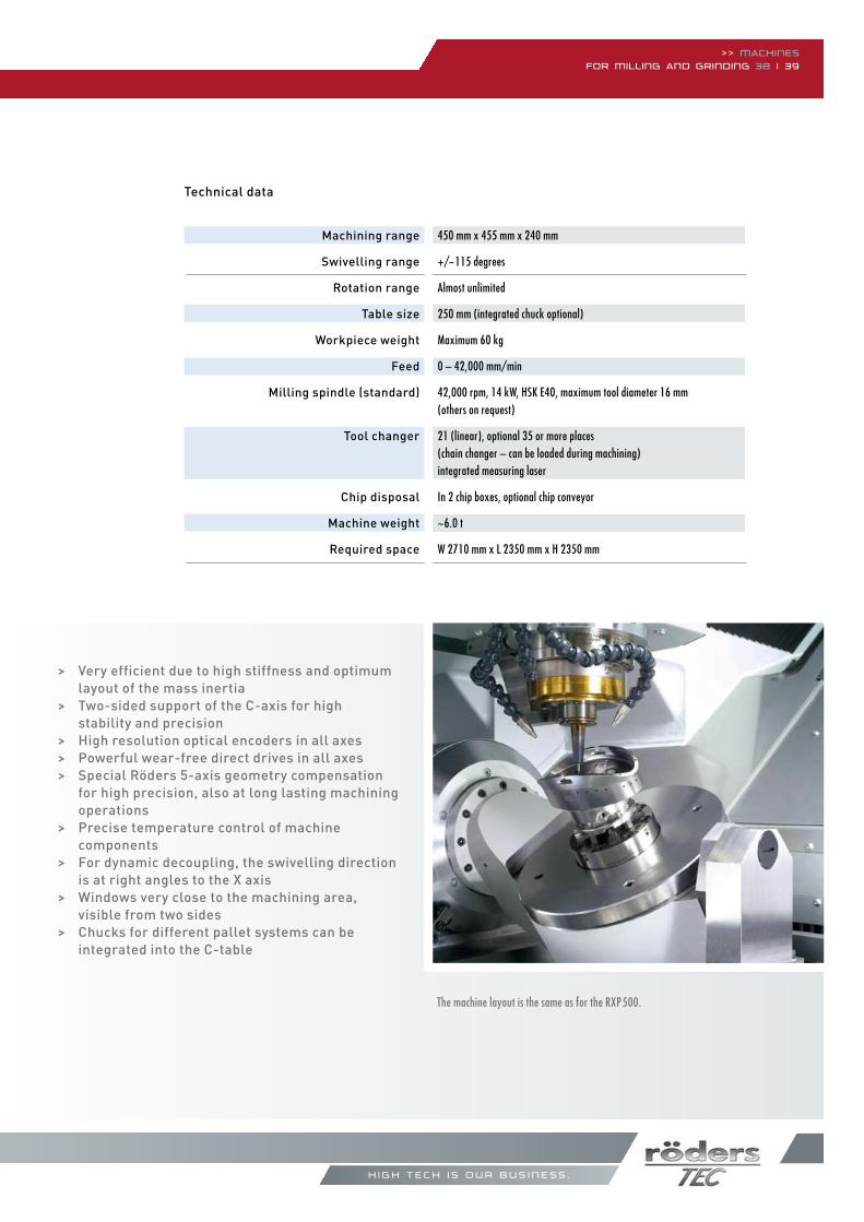
> Very efficient due to high stiffness and optimum layout of the mass inertia> Two-sided support of the C-axis for high stability and precision> High resolution optical encoders in all axes> Powerful wear-free direct drives in all axes> Special Röders 5-axis geometry compensation for high precision, also at long lasting machining operations> Precise temperature control of machine components> For dynamic decoupling, the swivelling direction is at right angles to the X axis> Windows very close to the machining area, visible from two sides> Chucks for different pallet systems can be integrated into the C-table
The machine layout is the same as for the RXP400.
310 mm x 294 mm x 210 mm
-30/+115 degrees
Almost unlimited
199 mm (integrated chuck optional)
Maximum 15 kg
0 – 42,000 mm/min
50,000 rpm, HSk e25 or 40,000 rpm, HSk e32,maximum tool diameter 6 mm for HSk e25 and 10 mm for HSk e32 (others on request)
16 (linear), optional 40, 70 or more places (chain changer – can be loaded during machining) integrated measuring laser
In 1 chip box, optional chip conveyor
~3.2 t
W 2515 mm x L 1930 mm x H 2080 mm
RödersRXP400 DSC
>> www.roeders.de
> Large swivel range up to 135°> Highly precise micro-machining> Electrodes, small moulds, watches etc.
RXP 400 DSC
25 m
m
9 mm *
90°
82 mm Y 212 mm73 mm Y 221 mm
Z = 210 mm
253
mm
68 m
m
-30/+135°
Z = 210 mmZ = 210 mm
253
mm 88
mm
180
mm
100 mm X 210 mm
RXP 400 DSC
25 m
m
9 mm *
90°
82 mm Y 212 mm73 mm Y 221 mm
Z = 210 mm
253
mm
68 m
m
-30/+135°
Z = 210 mmZ = 210 mm
253
mm 88
mm
180
mm
100 mm X 210 mm
* Dependent on the design of the cooling/spraying systems
>> Machinesfor Milling and grinding 34 | 35
h i g h t e c h i s o u r b u s i n e s s .
Machining range
Swivelling range
Rotation range
Table size
Workpiece weight
Feed
Milling spindle (standard)
Tool changer
Chip disposal
Machine weight
Required space
Technical data
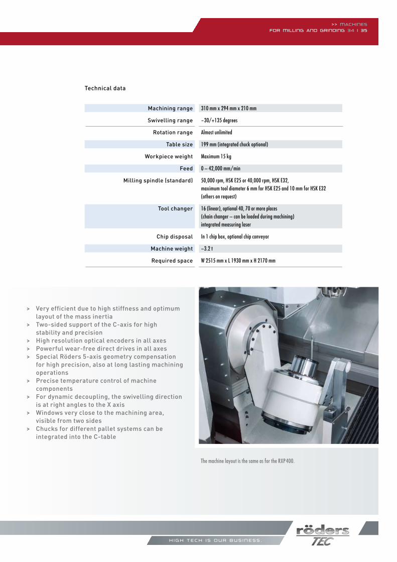
> Very efficient due to high stiffness and optimum layout of the mass inertia> Two-sided support of the C-axis for high stability and precision> High resolution optical encoders in all axes> Powerful wear-free direct drives in all axes> Special Röders 5-axis geometry compensation for high precision, also at long lasting machining operations> Precise temperature control of machine components> For dynamic decoupling, the swivelling direction is at right angles to the X axis> Windows very close to the machining area, visible from two sides> Chucks for different pallet systems can be integrated into the C-table
The machine layout is the same as for the RXP400.
310 mm x 294 mm x 210 mm
-30/+135 degrees
Almost unlimited
199 mm (integrated chuck optional)
Maximum 15 kg
0 – 42,000 mm/min
50,000 rpm, HSk e25 or 40,000 rpm, HSk e32,maximum tool diameter 6 mm for HSk e25 and 10 mm for HSk e32 (others on request)
16 (linear), optional 40, 70 or more places (chain changer – can be loaded during machining) integrated measuring laser
In 1 chip box, optional chip conveyor
~3.2 t
W 2515 mm x L 1930 mm x H 2170 mm
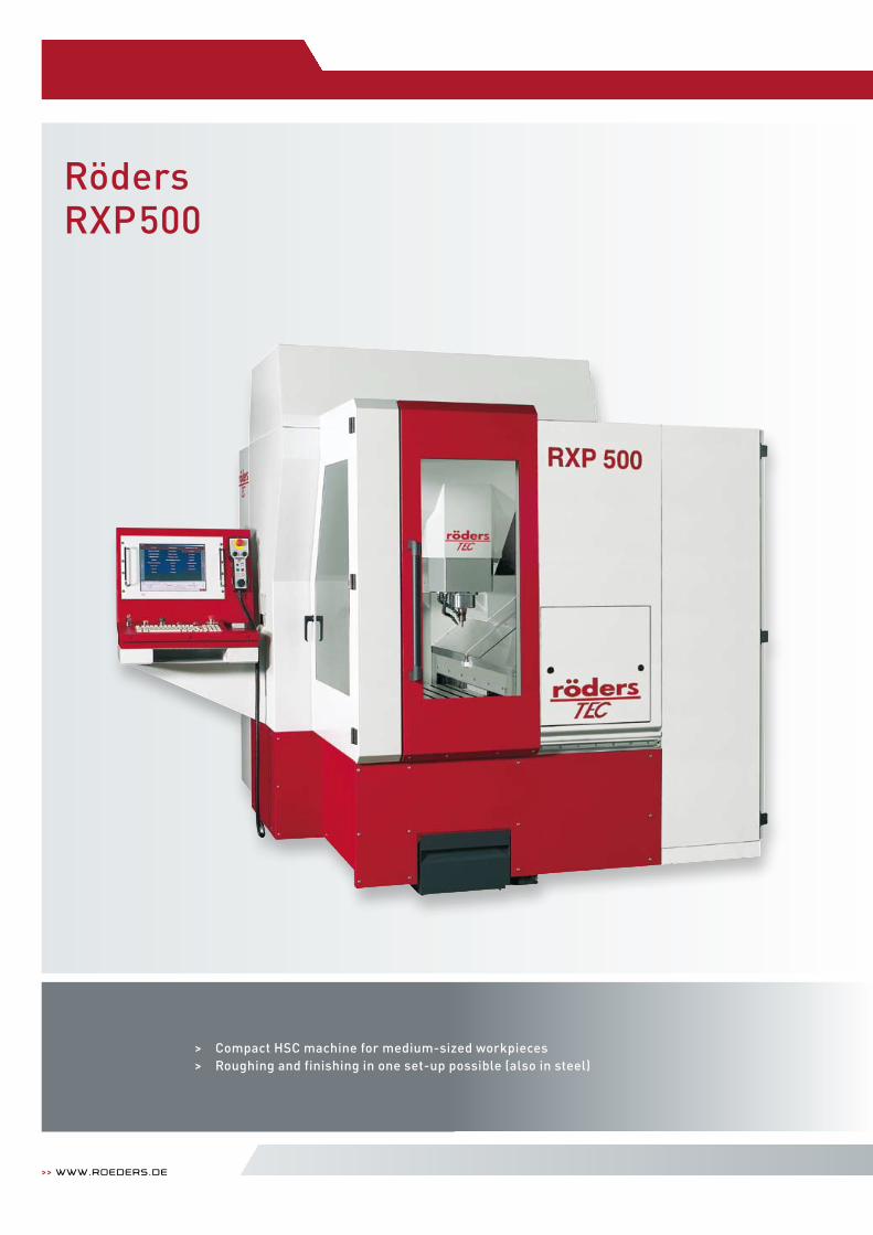
> Compact HSC machine for medium-sized workpieces> Roughing and finishing in one set-up possible (also in steel)
>> www.roeders.de
RödersRXP500
>> Machinesfor Milling and grinding 36 | 37
2150
mm
410
mm 660
mm
620 mm
2710 mm
910 mm
Terminal
Cooling unit
2000 mm
540 mm
RXP 500
655
mm
740 mm
Machining range
Table dimensions
Maximum height
Workpiece weight
Feed
Milling spindle (standard)
Tool changer
Chip disposal
Machine weight
Required space
Technical data
h i g h t e c h i s o u r b u s i n e s s .
500 mm x 455 mm x 240 mm
550 mm x 450 mm, T-slots 14 mm, distance 50 mm
450 mm, between spindle nose and machine table
Maximum 400 kg
0 – 42,000 mm/min
42,000 rpm, 14 kW, HSk e40, maximum tool diameter 16 mm (others on request)
21 (linear), optional 35 or more places (chain changer – can be loaded during machining) integrated measuring laser
In 2 chip boxes, optional chip conveyor
~5.5 t
W 2710 mm x L 2350 mm x H 2350 mm
>> www.roeders.de
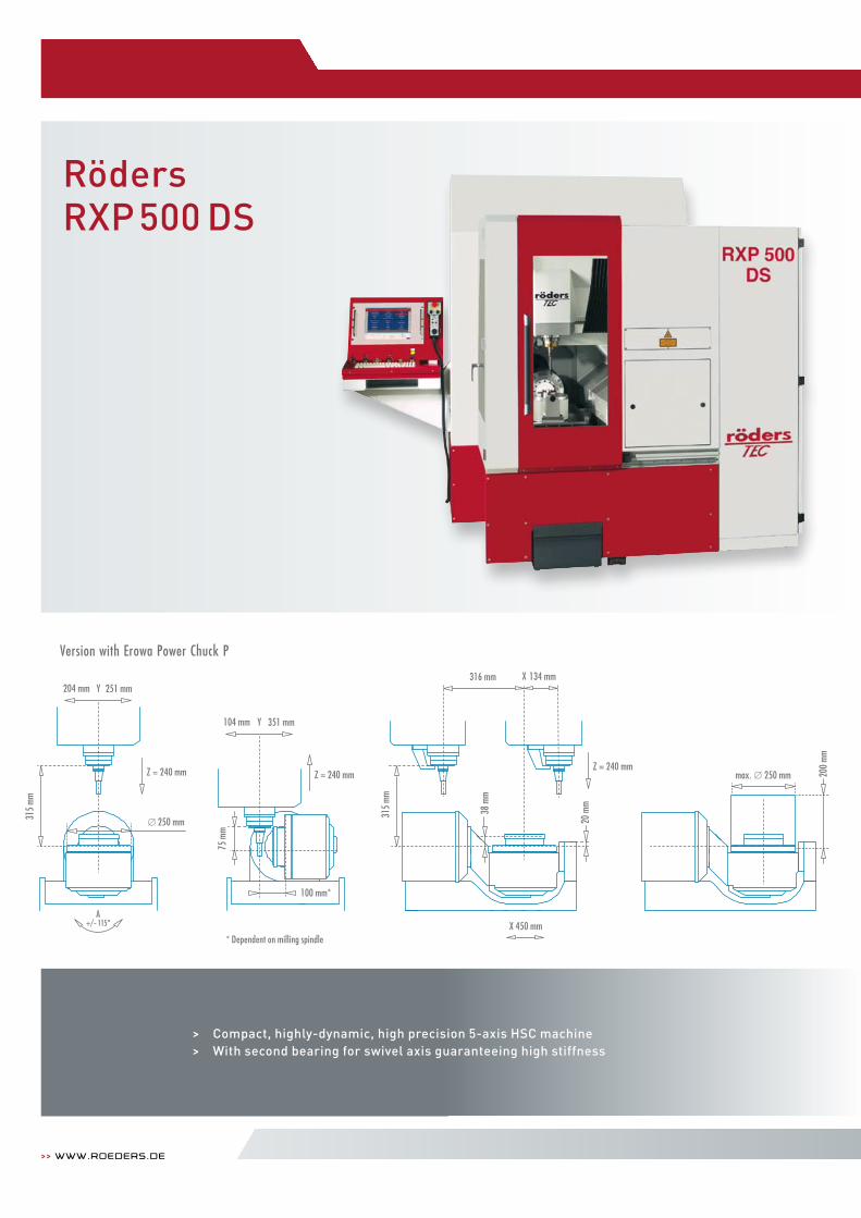
RödersRXP500 DS
> Compact, highly-dynamic, high precision 5-axis HSC machine> With second bearing for swivel axis guaranteeing high stiffness
* Dependent on milling spindle
Z = 240 mm
20 m
m
316 mm 134 mm
38 m
m
X
315
mm
X 450 mm
max. 250 mm 200
mm
75 m
m
104 mm Y 351 mm
100 mm*
Z = 240 mm
A+/- 115°
Z = 240 mm
204 mm Y 251 mm
250 mm315
mm
Version with erowa Power Chuck P
>> Machinesfor Milling and grinding 38 | 39
Machining range
Swivelling range
Rotation range
Table size
Workpiece weight
Feed
Milling spindle (standard)
Tool changer
Chip disposal
Machine weight
Required space
Technical data
The machine layout is the same as for the RXP500.
h i g h t e c h i s o u r b u s i n e s s .
> Very efficient due to high stiffness and optimum layout of the mass inertia> Two-sided support of the C-axis for high stability and precision> High resolution optical encoders in all axes> Powerful wear-free direct drives in all axes> Special Röders 5-axis geometry compensation for high precision, also at long lasting machining operations> Precise temperature control of machine components> For dynamic decoupling, the swivelling direction is at right angles to the X axis> Windows very close to the machining area, visible from two sides> Chucks for different pallet systems can be integrated into the C-table
450 mm x 455 mm x 240 mm +/-115 degrees
Almost unlimited 250 mm (integrated chuck optional)
Maximum 60 kg
0 – 42,000 mm/min 42,000 rpm, 14 kW, HSk e40, maximum tool diameter 16 mm (others on request)
21 (linear), optional 35 or more places (chain changer – can be loaded during machining) integrated measuring laser
In 2 chip boxes, optional chip conveyor
~6.0 t W 2710 mm x L 2350 mm x H 2350 mm
>> www.roeders.de
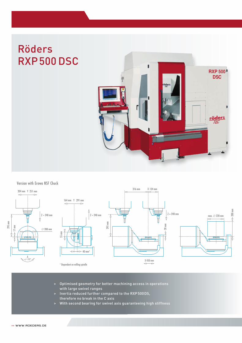
RödersRXP500 DSC
> Optimised geometry for better machining access in operations with large swivel ranges
> Inertia reduced further compared to the RXP 500DS, therefore no break in the C axis
> With second bearing for swivel axis guaranteeing high stiffness
A+/- 115°
55 m
m
164 mm Y
X
291 mm
40 mm*
Z = 240 mm
20 m
m
316 mm 134 mm
295
mm
17 m
m
max. 220 mm 200
mm
Z = 240 mm Z = 240 mm
204 mm Y 251 mm
200 mm295
mm
X 450 mm* Dependent on milling spindle
Version with erowa NSF Chuck
>> Machinesfor Milling and grinding 40 | 41
Machining range
Swivelling range
Rotation range
Table size
Workpiece weight
Feed
Milling spindle (standard)
Tool changer
Chip disposal
Machine weight
Required space
Technical data
The machine layout is the same as for the RXP500.
h i g h t e c h i s o u r b u s i n e s s .
> Very efficient due to high stiffness and optimum layout of the mass inertia> Two-sided support of the C-axis for high stability and precision> High resolution optical encoders in all axes> Powerful wear-free direct drives in all axes> Special Röders 5-axis geometry compensation for high precision, also at long lasting machining operations> Precise temperature control of machine components> For dynamic decoupling, the swivelling direction is at right angles to the X axis> Windows very close to the machining area, visible from two sides> Chucks for different pallet systems can be integrated into the C-table
450 mm x 455 mm x 240 mm
+/- 115 degrees
Almost unlimited 200 mm (integrated chuck optional)
Maximum 30 kg
0 – 42,000 mm/min 42,000 rpm, 14 kW, HSk e40, maximum tool diameter 16 mm (others on request)
21 (linear), optional 35 or more places (chain changer – can be loaded during machining) integrated measuring laser
In 2 chip boxes, optional chip conveyor
~6.0 t W 2710 mm x L 2350 mm x H 2350 mm
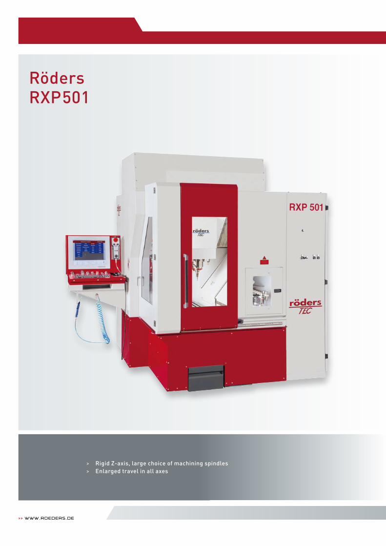
> Rigid Z-axis, large choice of machining spindles> Enlarged travel in all axes
>> www.roeders.de
RödersRXP501
2250
mm
3560
mm
1050
mm
730
mm
1523 mm 1200 mm 790 mm
1380
mm
600 mm
3515 mm
2095 mm
570 mm
>> Machinesfor Milling and grinding 42 | 43
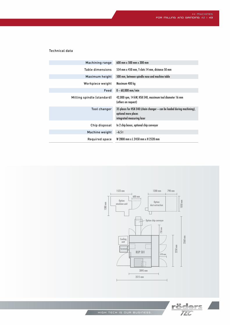
Machining range
Table dimensions
Maximum height
Workpiece weight
Feed
Milling spindle (standard)
Tool changer
Chip disposal
Machine weight
Required space
Technical data
h i g h t e c h i s o u r b u s i n e s s .
Terminal
Coolingunit
Optiondust extraction
Option chip conveyor
RXP 501
Optionemulsion unit
600 mm x 500 mm x 300 mm
554 mm x 450 mm, T-slots 14 mm, distance 50 mm
500 mm, between spindle nose and machine table
Maximum 400 kg
0 – 60,000 mm/min
42,000 rpm, 14 kW, HSk e40, maximum tool diameter 16 mm(others on request)
35 places for HSk e40 (chain changer – can be loaded during machining), optional more placesintegrated measuring laser
In 2 chip boxes, optional chip conveyor
~6.5 t
W 2800 mm x L 2450 mm x H 2520 mm
>> www.roeders.de
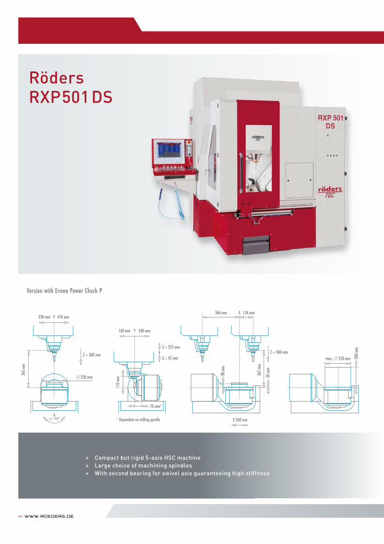
Version with erowa Power Chuck P
RödersRXP501 DS
> Compact but rigid 5-axis HSC machine> Large choice of machining spindles> With second bearing for swivel axis guaranteeing high stiffness
* Dependent on milling spindle
Z = 300 mmZ = 255 mm
Z = 45 mm
20 m
m
110
mm
160 mm Y 540 mm
70 mm*
max. 250 mm 200
mm
366 mm 134 mm
38 m
m
Z = 300 mm
A+/- 115°
230 mm Y 470 mm
250 mm
365
mm
365
mm
X 500 mm
X
>> Machinesfor Milling and grinding 44 | 45
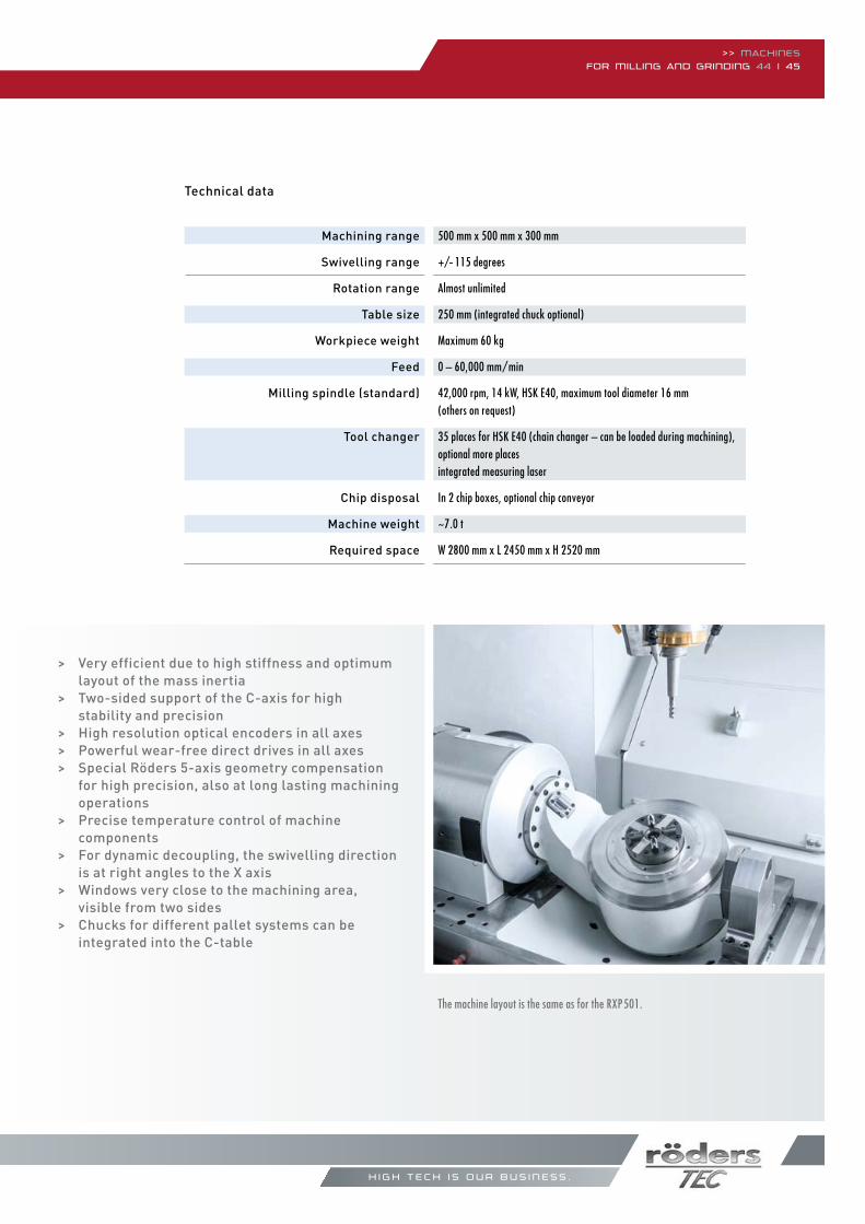
Machining range
Swivelling range
Rotation range
Table size
Workpiece weight
Feed
Milling spindle (standard)
Tool changer
Chip disposal
Machine weight
Required space
Technical data
The machine layout is the same as for the RXP501.
h i g h t e c h i s o u r b u s i n e s s .
> Very efficient due to high stiffness and optimum layout of the mass inertia> Two-sided support of the C-axis for high stability and precision> High resolution optical encoders in all axes> Powerful wear-free direct drives in all axes> Special Röders 5-axis geometry compensation for high precision, also at long lasting machining operations> Precise temperature control of machine components> For dynamic decoupling, the swivelling direction is at right angles to the X axis> Windows very close to the machining area, visible from two sides> Chucks for different pallet systems can be integrated into the C-table
500 mm x 500 mm x 300 mm
+/- 115 degrees
Almost unlimited
250 mm (integrated chuck optional)
Maximum 60 kg
0 – 60,000 mm/min
42,000 rpm, 14 kW, HSk e40, maximum tool diameter 16 mm (others on request)
35 places for HSk e40 (chain changer – can be loaded during machining), optional more placesintegrated measuring laser
In 2 chip boxes, optional chip conveyor
~7.0 t
W 2800 mm x L 2450 mm x H 2520 mm
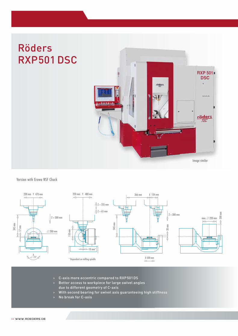
>> www.roeders.de
RödersRXP501 DSC
> C-axis more eccentric compared to RXP 501 DS> Better access to workpiece for large swivel angles due to different geometry of C-axis> With second bearing for swivel axis guaranteeing high stiffness> No break for C-axis
Image similar
* Dependent on milling spindle
Version with erowa NSF Chuck
A+/- 115°
Z = 235 mm
Z = 65 mm
110
mm
220 mm Y 480 mm
17 m
m
max. 220 mm 200
mm
Z = 300 mm
230 mm Y 470 mm
200 mm
345
mm
10 mm*
Z = 300 mm
20 m
m
366 mm 134 mm
345
mm
X 500 mm
X
>> Machinesfor Milling and grinding 46 | 47
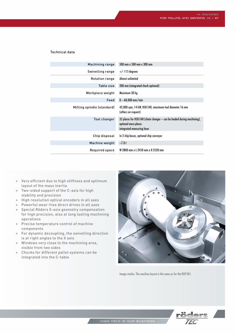
Machining range
Swivelling range
Rotation range
Table size
Workpiece weight
Feed
Milling spindle (standard)
Tool changer
Chip disposal
Machine weight
Required space
Technical data
Image similar. The machine layout is the same as for the RXP501.
h i g h t e c h i s o u r b u s i n e s s .
> Very efficient due to high stiffness and optimum layout of the mass inertia> Two-sided support of the C-axis for high stability and precision> High resolution optical encoders in all axes> Powerful wear-free direct drives in all axes> Special Röders 5-axis geometry compensation for high precision, also at long lasting machining operations> Precise temperature control of machine components> For dynamic decoupling, the swivelling direction is at right angles to the X axis> Windows very close to the machining area, visible from two sides> Chucks for different pallet systems can be integrated into the C-table
500 mm x 500 mm x 300 mm
+/- 115 degrees
Almost unlimited
200 mm (integrated chuck optional)
Maximum 30 kg
0 – 60,000 mm/min
42,000 rpm, 14 kW, HSk e40, maximum tool diameter 16 mm (others on request)
35 places for HSk e40 (chain changer – can be loaded during machining), optional more placesintegrated measuring laser
In 2 chip boxes, optional chip conveyor
~7.0 t
W 2800 mm x L 2450 mm x H 2520 mm
>> www.roeders.de
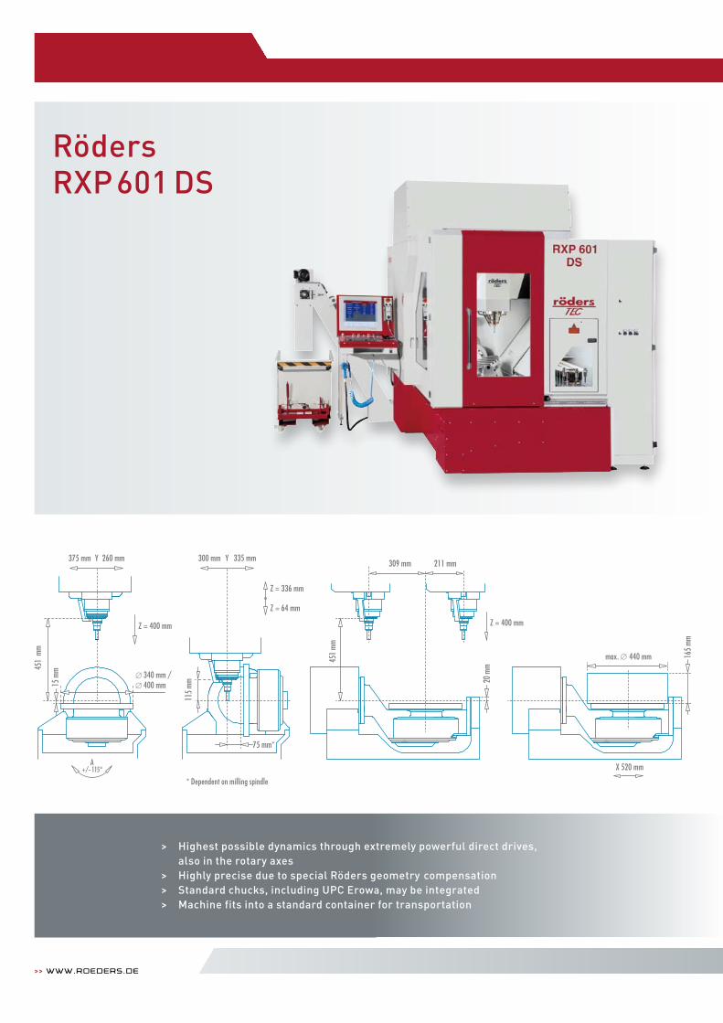
RödersRXP601 DS
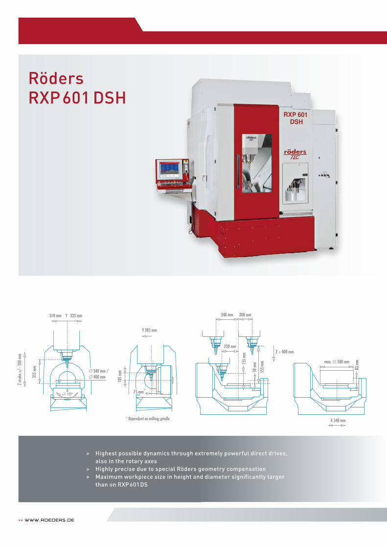
> Highest possible dynamics through extremely powerful direct drives, also in the rotary axes
> Highly precise due to special Röders geometry compensation > Standard chucks, including UPC Erowa, may be integrated> Machine fits into a standard container for transportation
A+/- 115°
Z = 400 mm
375 mm Y 260 mm
400 mm340 mm /
451
mm
max. 440 mm 165
mm
X 520 mm
15 m
m
Z = 336 mm
Z = 64 mm
115
mm
300 mm Y 335 mm
75 mm*
Z = 400 mm
20 m
m
309 mm 211 mm
451
mm
* Dependent on milling spindle
>> Machinesfor Milling and grinding 48 | 49
Machining range
Swivelling range
Rotation range
Table size
Workpiece weight
Feed
Milling spindle (standard)
Tool changer
Chip disposal
Machine weight
Required space
Technical data
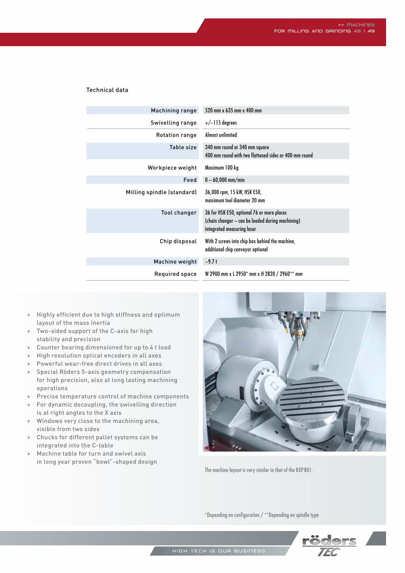
> Highly efficient due to high stiffness and optimum layout of the mass inertia
> Two-sided support of the C-axis for high stability and precision> Counter bearing dimensioned for up to 4 t load> High resolution optical encoders in all axes> Powerful wear-free direct drives in all axes> Special Röders 5-axis geometry compensation for high precision, also at long lasting machining operations> Precise temperature control of machine components> For dynamic decoupling, the swivelling direction is at right angles to the X axis> Windows very close to the machining area, visible from two sides> Chucks for different pallet systems can be integrated into the C-table> Machine table for turn and swivel axis in long year proven “bowl”-shaped design
h i g h t e c h i s o u r b u s i n e s s .
The machine layout is very similar to that of the RXP 801.
*Depending on configuration / **Depending on spindle type
520 mm x 635 mm x 400 mm
+/-115 degrees
Almost unlimited 340 mm round or 340 mm square400 mm round with two flattened sides or 400 mm round
Maximum 100 kg
0 – 60,000 mm/min 36,000 rpm, 15 kW, HSk e50,maximum tool diameter 20 mm
36 for HSk e50, optional 76 or more places(chain changer – can be loaded during machining)integrated measuring laser
With 2 screws into chip box behind the machine,additional chip conveyor optional
~9.7 t W 2900 mm x L 2950* mm x H 2820 / 2960** mm
>> www.roeders.de
RödersRXP601 DSH
> Highest possible dynamics through extremely powerful direct drives, also in the rotary axes
> Highly precise due to special Röders geometry compensation > Maximum workpiece size in height and diameter significantly larger than on RXP601DS
* Dependent on milling spindle
Z str
oke +
/- 2
00 m
m
max. 500 mm83
mm
555
mm
340 mm
250 mm
X 540 mm
200 mm
Z = 400 mm
155
mm
310 mm Y 325 mm
355
mm
Z-Hu
b +/
- 200
mm
A+/- 115°
105
mm
Y 285 mm
* Abhängig von der Frässpindel
340 mm /400 mm
*75 mm
50 m
m max. 500 mm83
mm
555
mm
340 mm
250 mm
X 540 mm
200 mm
Z = 400 mm
155
mm
310 mm Y 325 mm
355
mm
Z-Hu
b +/
- 200
mm
A+/- 115°
105
mm
Y 285 mm
* Abhängig von der Frässpindel
340 mm /400 mm
*75 mm
50 m
m max. 500 mm83
mm
555
mm
340 mm
250 mm
X 540 mm
200 mm
Z = 400 mm
155
mm
310 mm Y 325 mm
355
mm
Z-Hu
b +/
- 200
mm
A+/- 115°
105
mm
Y 285 mm
* Abhängig von der Frässpindel
340 mm /400 mm
*75 mm
50 m
m max. 500 mm83
mm
555
mm
340 mm
250 mm
X 540 mm
200 mm
Z = 400 mm
155
mm
310 mm Y 325 mm
355
mm
Z-Hu
b +/
- 200
mm
A+/- 115°
105
mm
Y 285 mm
* Abhängig von der Frässpindel
340 mm /400 mm
*75 mm
50 m
m
>> Machinesfor Milling and grinding 50 | 51
Machining range
Swivelling range
Rotation range
Table size
Workpiece weight
Feed
Milling spindle (standard)
Tool changer
Chip disposal
Machine weight
Required space
Technical data
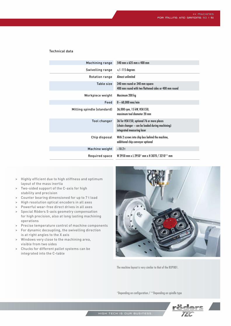
> Highly efficient due to high stiffness and optimum layout of the mass inertia
> Two-sided support of the C-axis for high stability and precision> Counter bearing dimensioned for up to 7 t load> High resolution optical encoders in all axes> Powerful wear-free direct drives in all axes> Special Röders 5-axis geometry compensation for high precision, also at long lasting machining operations> Precise temperature control of machine components> For dynamic decoupling, the swivelling direction is at right angles to the X axis> Windows very close to the machining area, visible from two sides> Chucks for different pallet systems can be integrated into the C-table
h i g h t e c h i s o u r b u s i n e s s .
The machine layout is very similar to that of the RXP801.
540 mm x 635 mm x 400 mm
+/-115 degrees
Almost unlimited 340 mm round or 340 mm square400 mm round with two flattened sides or 400 mm round
Maximum 200 kg
0 – 60,000 mm/min 36,000 rpm, 15 kW, HSk e50,maximum tool diameter 20 mm
36 for HSk e50, optional 76 or more places(chain changer – can be loaded during machining)integrated measuring laser
With 2 screws into chip box behind the machine,additional chip conveyor optional
~10.2 t W 2950 mm x L 2950* mm x H 3070 / 3210** mm
*Depending on configuration / **Depending on spindle type
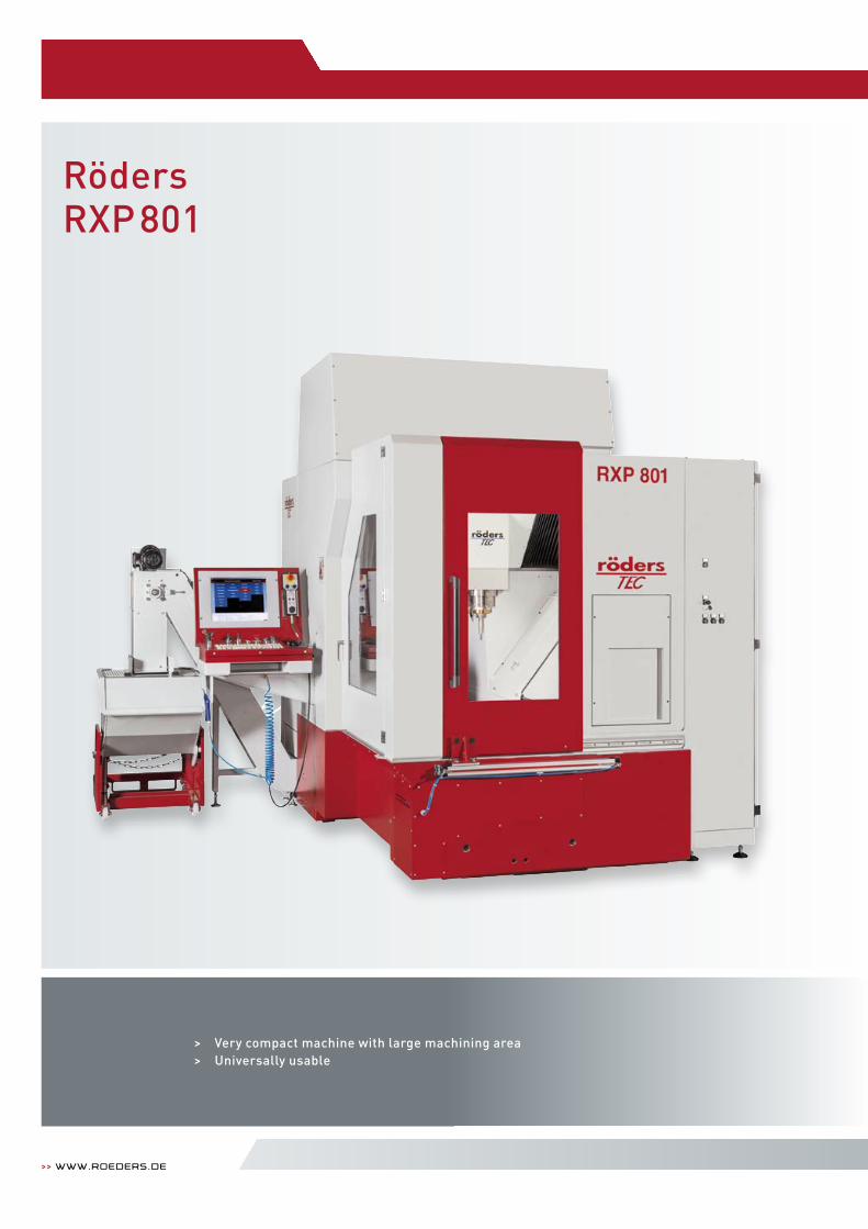
> Very compact machine with large machining area> Universally usable
>> www.roeders.de
RödersRXP801
>> Machinesfor Milling and grinding 52 | 53
Machining range
Table dimensions
Maximum height
Workpiece weight
Feed
Milling spindle (standard)
Tool changer
Chip disposal
Machine weight
Required space
Technical data
h i g h t e c h i s o u r b u s i n e s s .
Cooling unit
Optionemulsion unit
Optiondust extraction
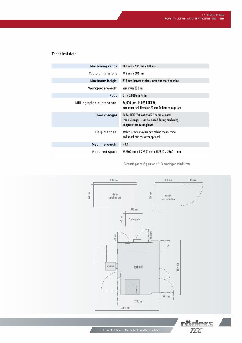
800 mm x 635 mm x 400 mm
796 mm x 596 mm
615 mm, between spindle nose and machine table
Maximum 800 kg
0 – 60,000 mm/min
36,000 rpm, 15 kW, HSk e50,maximum tool diameter 20 mm (others on request)
36 for HSk e50, optional 76 or more places(chain changer – can be loaded during machining)integrated measuring laser
With 2 screws into chip box behind the machine,additional chip conveyor optional
~8.4 t
W 2900 mm x L 2950* mm x H 2820 / 2960** mm
*Depending on configuration / **Depending on spindle type
660
mm
900 mm
1400
mm
1400 mm 1135 mm28
44 m
m
Maschinenfüße
0 1 m
RXP 801
2200 mm
3444 mm
516
mm 682
mm
765 mm
970
mm
2300 mm
Terminal
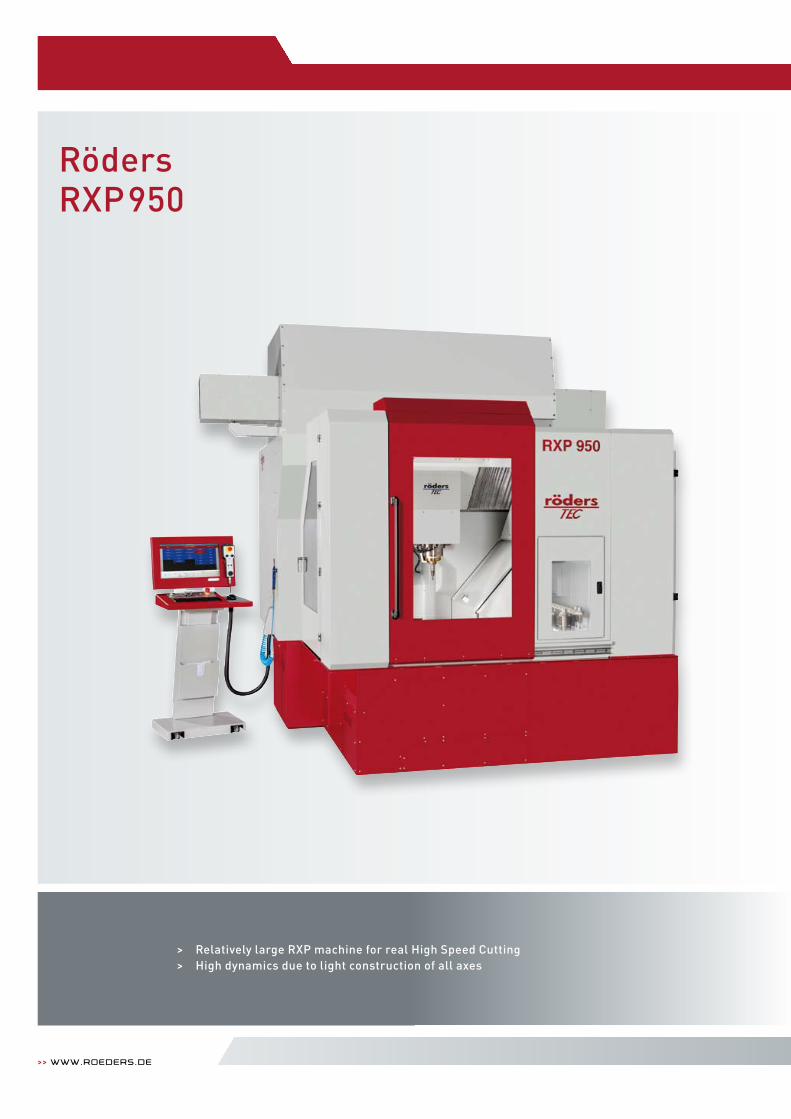
RödersRXP950
>> www.roeders.de
> Relatively large RXP machine for real High Speed Cutting> High dynamics due to light construction of all axes
Machining range
Table dimensions
Maximum height
Workpiece weight
Feed
Milling spindle (standard)
Tool changer
Chip disposal
Machine weight
Required space
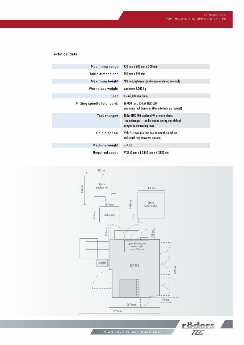
950 mm x 905 mm x 500 mm
950 mm x 796 mm
700 mm, between spindle nose and machine table
Maximum 2.000 kg
0 – 60,000 mm/min
36,000 rpm, 15 kW, HSk e50,maximum tool diameter 20 mm (others on request)
40 for HSk e50, optional 94 or more places(chain changer – can be loaded during machining)integrated measuring laser
With 2 screws into chip box behind the machine,additional chip conveyor optional
~14.5 t
W 3350 mm x L 3350 mm x H 3180 mm
Technical data
>> Machinesfor Milling and grinding 54 | 55
h i g h t e c h i s o u r b u s i n e s s .
750
mm
1050 mm
1400
mm
1400 mm
3350
mm
Maschinenfüße
0 1 m
794
mm
552
mm
2670 mm
4225 mm
592 mm
1380
mm
1523 mm
RXP 950Terminal
Cooling unit
Optiondust extraction
Optionemulsion unit
Option: oil mist suctionMachine height
approx. 3030 mm
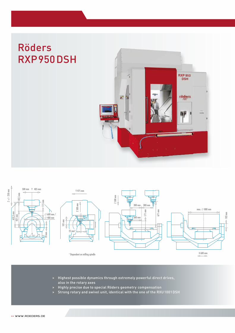
RödersRXP950 DSH
>> www.roeders.de
Z 50
0 m
m
300 mm
300 mm300 mm
max. 800 mm
103
mm
X 600 mm
652,
5 m
m42
1 m
m14
2,5
mm
101
mm
70 m
m
Z +/
- 25
0 m
m
A+/- 115°
500 mm Y 405 mmY 475 mm
25 mm*
171
mm
671
mm
600 mm /400 mm
Z 50
0 m
m
115
mm
* Dependent on milling spindle
> Highest possible dynamics through extremely powerful direct drives, also in the rotary axes
> Highly precise due to special Röders geometry compensation > Strong rotary and swivel unit, identical with the one of the RXU 1001 DSH
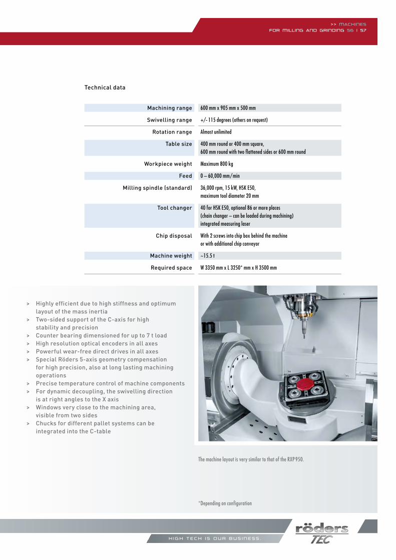
>> Machinesfor Milling and grinding 56 | 57
Machining range
Swivelling range
Rotation range
Table size
Workpiece weight
Feed
Milling spindle (standard)
Tool changer
Chip disposal
Machine weight
Required space
Technical data
h i g h t e c h i s o u r b u s i n e s s .
The machine layout is very similar to that of the RXP 950.
600 mm x 905 mm x 500 mm
+/- 115 degrees (others on request)
Almost unlimited
400 mm round or 400 mm square, 600 mm round with two flattened sides or 600 mm round
Maximum 800 kg
0 – 60,000 mm/min
36,000 rpm, 15 kW, HSk e50, maximum tool diameter 20 mm
40 for HSk e50, optional 86 or more places(chain changer – can be loaded during machining)integrated measuring laser
With 2 screws into chip box behind the machineor with additional chip conveyor
~15.5 t
W 3350 mm x L 3250* mm x H 3500 mm
> Highly efficient due to high stiffness and optimum layout of the mass inertia
> Two-sided support of the C-axis for high stability and precision> Counter bearing dimensioned for up to 7 t load> High resolution optical encoders in all axes> Powerful wear-free direct drives in all axes> Special Röders 5-axis geometry compensation for high precision, also at long lasting machining operations> Precise temperature control of machine components> For dynamic decoupling, the swivelling direction is at right angles to the X axis> Windows very close to the machining area, visible from two sides> Chucks for different pallet systems can be integrated into the C-table
*Depending on configuration
>> www.roeders.de
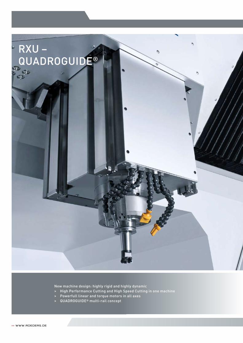
RXU –QUADROGUIDE®
New machine design: highly rigid and highly dynamic> High Performance Cutting and High Speed Cutting in one machine> Powerfull linear and torque motors in all axes> QUADROGUIDE® multi-rail concept
>> Machinesfor Milling and grinding 58 | 59
h i g h t e c h i s o u r b u s i n e s s .
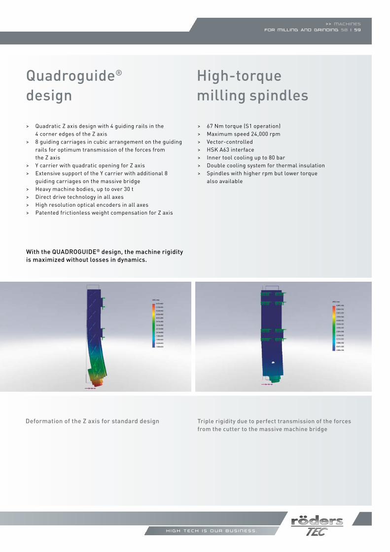
Quadroguide® design
> Quadratic Z axis design with 4 guiding rails in the 4 corner edges of the Z axis> 8 guiding carriages in cubic arrangement on the guiding rails for optimum transmission of the forces from the Z axis> Y carrier with quadratic opening for Z axis> Extensive support of the Y carrier with additional 8 guiding carriages on the massive bridge> Heavy machine bodies, up to over 30 t> Direct drive technology in all axes> High resolution optical encoders in all axes> Patented frictionless weight compensation for Z axis
Triple rigidity due to perfect transmission of the forces from the cutter to the massive machine bridge
High-torque milling spindles
> 67 Nm torque (S1 operation) > Maximum speed 24,000 rpm> Vector-controlled> HSK A63 interface> Inner tool cooling up to 80 bar> Double cooling system for thermal insulation> Spindles with higher rpm but lower torque also available
Deformation of the Z axis for standard design
With the QUADROGUIDE® design, the machine rigidity is maximized without losses in dynamics.
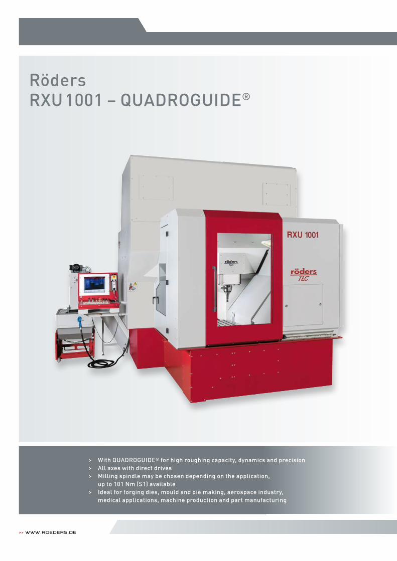
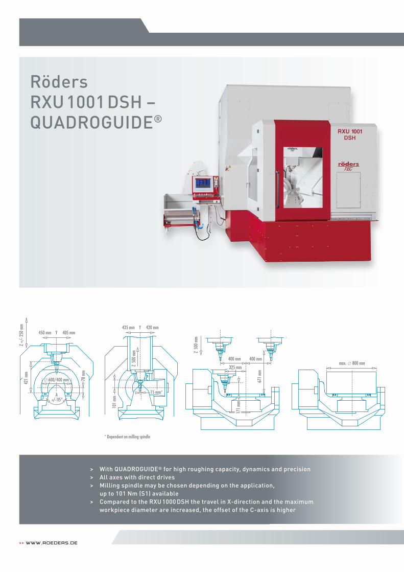
RödersRXU1001 – QUADROGUIDE®
>> www.roeders.de
> With QUADROGUIDE® for high roughing capacity, dynamics and precision> All axes with direct drives> Milling spindle may be chosen depending on the application, up to 101 Nm (S1) available> Ideal for forging dies, mould and die making, aerospace industry, medical applications, machine production and part manufacturing
Machining range
Table dimensions
Maximum height
Workpiece weight
Feed
Milling spindle (standard)
Tool changer
Chip disposal
Machine weight
Required space
Technical data
>> Machinesfor Milling and grinding 60 | 61
h i g h t e c h i s o u r b u s i n e s s .
4814
mm
(512
0 mm
with
HC-
E too
l cha
nger
)
1523 mm 1050 mm
1380
mm 750
mm
4058 mm
3456 mm
0 1 m
493
mm
544 mm
600 mm
481 mm
493
mm
2205 mm
448 mm
Cooling unit
4814
mm
(512
0 m
m w
ith H
C-e t
ool c
hang
er)
Optionemulsion unit
Terminal
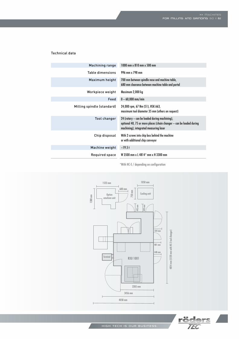
1000 mm x 810 mm x 500 mm
996 mm x 798 mm
700 mm between spindle nose and machine table,680 mm clearance between machine table and portal
Maximum 2,000 kg
0 – 60,000 mm/min
24,000 rpm, 67 Nm (S1), HSk A63, maximum tool diameter 35 mm (others on request)
24 (rotary – can be loaded during machining), optional 40, 75 or more places (chain changer – can be loaded duringmachining), integrated measuring laser
With 2 screws into chip box behind the machine or with additional chip conveyor
~19.5 t
W 3500 mm x L 4814* mm x H 3300 mm
RXU 1001
*With HC-e / depending on configuration
>> www.roeders.de
RödersRXU1001 DSH –QUADROGUIDE®
* Dependent on milling spindle
420 mm 435 mm Y
max. 800 mm
101
mm
Z 50
0 m
m
* Abhängig von der Frässpindel
Z 50
0 m
m
671
mm
400 mm400 mm
171
mm
325 mm
15 mm*
405 mm450 mm Y
Z +/
- 250
mm
A+/-115°
421
mm
600/400 mm 70 m
m
420 mm 435 mm Y
max. 800 mm
101
mm
Z 50
0 m
m
* Abhängig von der Frässpindel
Z 50
0 m
m
671
mm
400 mm400 mm
171
mm
325 mm
15 mm*
405 mm450 mm Y
Z +/
- 250
mm
A+/-115°
421
mm
600/400 mm 70 m
m
> With QUADROGUIDE® for high roughing capacity, dynamics and precision> All axes with direct drives> Milling spindle may be chosen depending on the application, up to 101 Nm (S1) available> Compared to the RXU 1000 DSH the travel in X-direction and the maximum workpiece diameter are increased, the offset of the C-axis is higher
>> Machinesfor Milling and grinding 62 | 63
h i g h t e c h i s o u r b u s i n e s s .
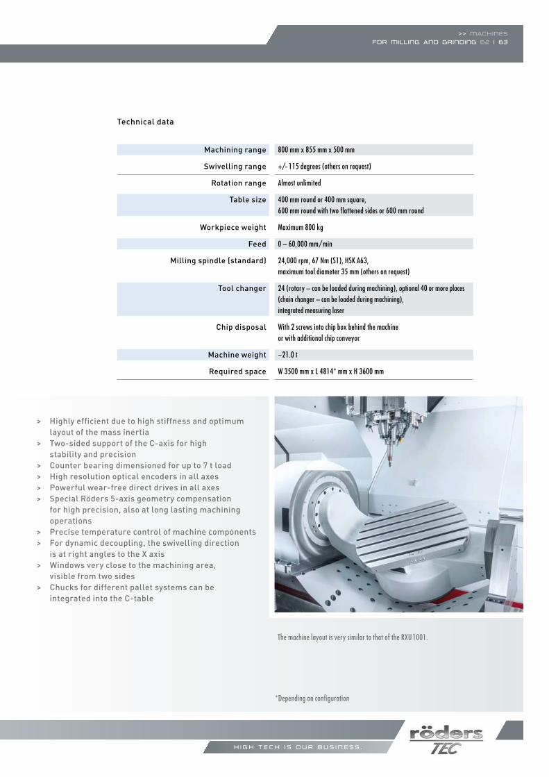
The machine layout is very similar to that of the RXU1001.
Machining range
Swivelling range
Rotation range
Table size
Workpiece weight
Feed
Milling spindle (standard)
Tool changer
Chip disposal
Machine weight
Required space
Technical data
> Highly efficient due to high stiffness and optimum layout of the mass inertia
> Two-sided support of the C-axis for high stability and precision> Counter bearing dimensioned for up to 7 t load> High resolution optical encoders in all axes> Powerful wear-free direct drives in all axes> Special Röders 5-axis geometry compensation for high precision, also at long lasting machining operations> Precise temperature control of machine components> For dynamic decoupling, the swivelling direction is at right angles to the X axis> Windows very close to the machining area, visible from two sides> Chucks for different pallet systems can be integrated into the C-table
800 mm x 855 mm x 500 mm
+/- 115 degrees (others on request)
Almost unlimited
400 mm round or 400 mm square, 600 mm round with two flattened sides or 600 mm round
Maximum 800 kg
0 – 60,000 mm/min
24,000 rpm, 67 Nm (S1), HSk A63, maximum tool diameter 35 mm (others on request)
24 (rotary – can be loaded during machining), optional 40 or more places (chain changer – can be loaded during machining),integrated measuring laser
With 2 screws into chip box behind the machineor with additional chip conveyor
~21.0 t
W 3500 mm x L 4814* mm x H 3600 mm
*Depending on configuration
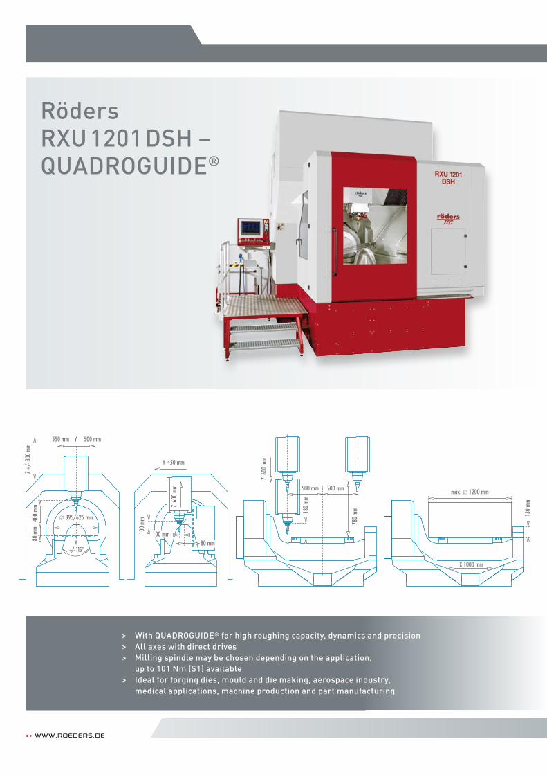
RödersRXU1201 DSH –QUADROGUIDE®
>> www.roeders.de
Z +/
- 300
mm
Z 60
0 m
m
550 mm Y 500 mm
max. 1200 mm
130
mm
X 1000 mm
400
mm
80 m
m
A+/- 115°
895/625 mm
100
mm
180
mm
780
mm
Z 60
0 m
m
500 mm 500 mm
450 mmY
100 mm80 mm
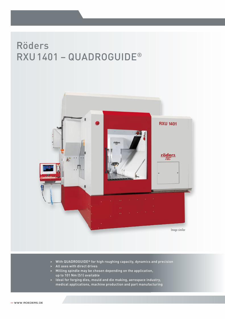
> With QUADROGUIDE® for high roughing capacity, dynamics and precision> All axes with direct drives> Milling spindle may be chosen depending on the application, up to 101 Nm (S1) available> Ideal for forging dies, mould and die making, aerospace industry, medical applications, machine production and part manufacturing
Machining range
Swivelling range
Rotation range
Table size
Workpiece weight
Feed
Milling spindle (standard)
Tool changer
Chip disposal
Machine weight
Required space
Technical data
The machine layout is very similar to that of the RXU1401.
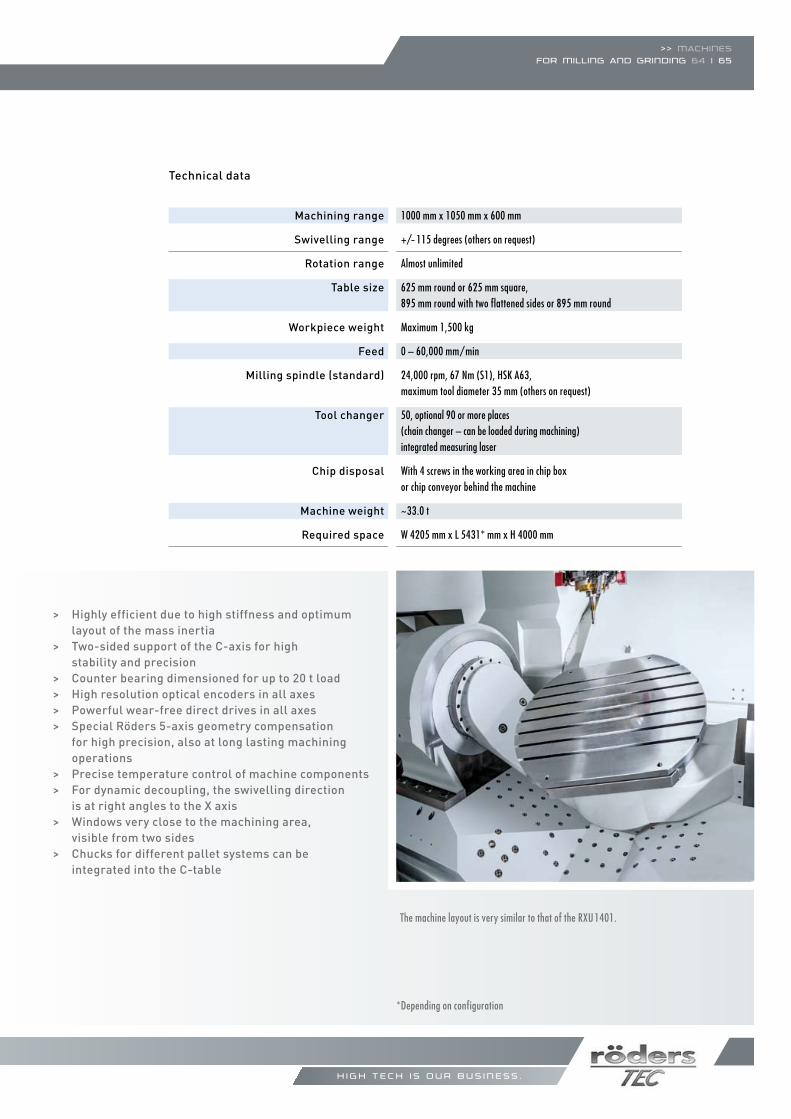
> Highly efficient due to high stiffness and optimum layout of the mass inertia
> Two-sided support of the C-axis for high stability and precision> Counter bearing dimensioned for up to 20 t load> High resolution optical encoders in all axes> Powerful wear-free direct drives in all axes> Special Röders 5-axis geometry compensation for high precision, also at long lasting machining operations> Precise temperature control of machine components> For dynamic decoupling, the swivelling direction is at right angles to the X axis> Windows very close to the machining area, visible from two sides> Chucks for different pallet systems can be integrated into the C-table
>> Machinesfor Milling and grinding 64 | 65
h i g h t e c h i s o u r b u s i n e s s .
1000 mm x 1050 mm x 600 mm
+/- 115 degrees (others on request)
Almost unlimited
625 mm round or 625 mm square, 895 mm round with two flattened sides or 895 mm round
Maximum 1,500 kg
0 – 60,000 mm/min
24,000 rpm, 67 Nm (S1), HSk A63, maximum tool diameter 35 mm (others on request)
50, optional 90 or more places (chain changer – can be loaded during machining)integrated measuring laser
With 4 screws in the working area in chip boxor chip conveyor behind the machine
~33.0 t
W 4205 mm x L 5431* mm x H 4000 mm
*Depending on configuration
>> www.roeders.de
RödersRXU1401 – QUADROGUIDE®
> With QUADROGUIDE® for high roughing capacity, dynamics and precision> All axes with direct drives> Milling spindle may be chosen depending on the application, up to 101 Nm (S1) available> Ideal for forging dies, mould and die making, aerospace industry, medical applications, machine production and part manufacturing
Image similar
>> Machinesfor Milling and grinding 66 | 67
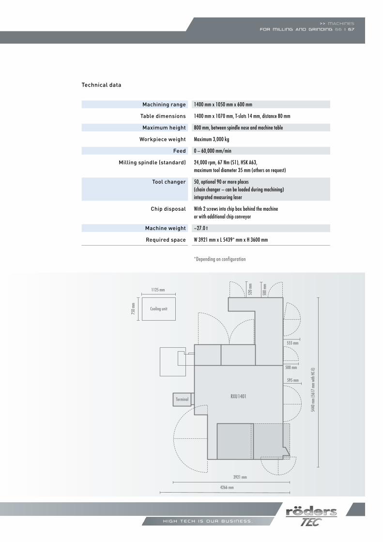
Machining range
Table dimensions
Maximum height
Workpiece weight
Feed
Milling spindle (standard)
Tool changer
Chip disposal
Machine weight
Required space
Technical data
h i g h t e c h i s o u r b u s i n e s s .
Maschinenfüße
0 1 m
520
mm
555 mm
500 mm
500
mm
750
mm
1125 mm
4266 mm
3921 mm
5440
mm
(561
7 mm
with
HC-
E)
595 mm
RXU1401Terminal
Cooling unit
1400 mm x 1050 mm x 600 mm
1400 mm x 1070 mm, T-slots 14 mm, distance 80 mm
800 mm, between spindle nose and machine table
Maximum 3,000 kg
0 – 60,000 mm/min
24,000 rpm, 67 Nm (S1), HSk A63, maximum tool diameter 35 mm (others on request)
50, optional 90 or more places (chain changer – can be loaded during machining)integrated measuring laser
With 2 screws into chip box behind the machine or with additional chip conveyor
~27.0 t
W 3921 mm x L 5439* mm x H 3600 mm
*Depending on configuration
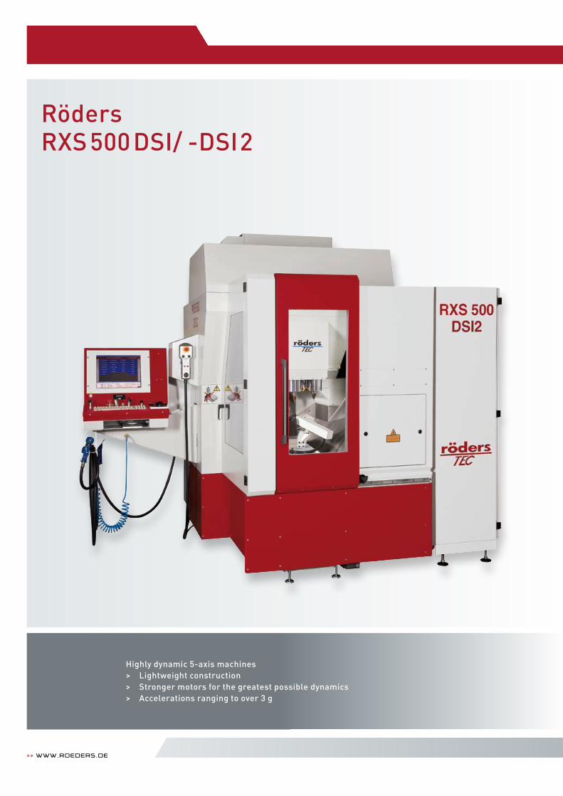
Highly dynamic 5-axis machines> Lightweight construction> Stronger motors for the greatest possible dynamics> Accelerations ranging to over 3 g
>> www.roeders.de
RödersRXS500 DSI/ -DSI2
>> Machinesfor Milling and grinding 68 | 69
h i g h t e c h i s o u r b u s i n e s s .
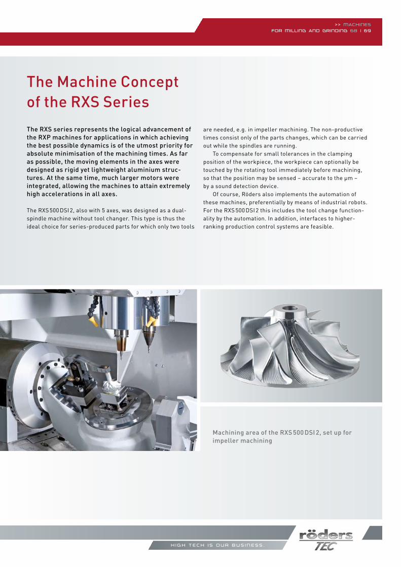
The Machine Concept of the RXS SeriesThe RXS series represents the logical advancement of the RXP machines for applications in which achieving the best possible dynamics is of the utmost priority for absolute minimisation of the machining times. As far as possible, the moving elements in the axes were designed as rigid yet lightweight aluminium struc-tures. At the same time, much larger motors were integrated, allowing the machines to attain extremely high accelerations in all axes.
The RXS 500 DSI 2, also with 5 axes, was designed as a dual-spindle machine without tool changer. This type is thus the ideal choice for series-produced parts for which only two tools
are needed, e.g. in impeller machining. The non-productive times consist only of the parts changes, which can be carried out while the spindles are running. To compensate for small tolerances in the clamping position of the workpiece, the workpiece can optionally be touched by the rotating tool immediately before machining, so that the position may be sensed – accurate to the µm – by a sound detection device. Of course, Röders also implements the automation of these machines, preferentially by means of industrial robots. For the RXS 500 DSI 2 this includes the tool change function-ality by the automation. In addition, interfaces to higher- ranking production control systems are feasible.
Machining area of the RXS 500 DSI 2, set up for impeller machining
>> www.roeders.de
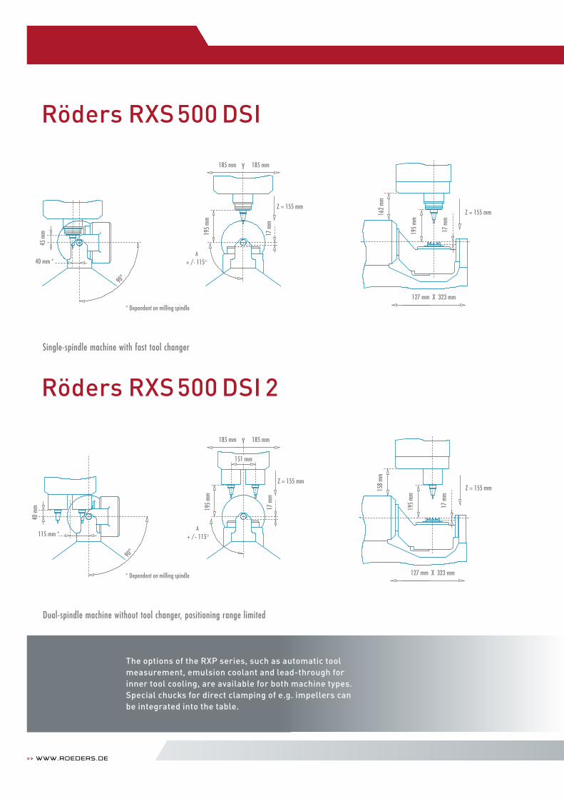
The options of the RXP series, such as automatic tool measurement, emulsion coolant and lead-through for inner tool cooling, are available for both machine types.Special chucks for direct clamping of e.g. impellers can be integrated into the table.
45 m
m
40 mm *
185 mm Y 185 mm
Z = 155 mm
A+ /- 115°
195
mm
127 mm X 323 mm
Z = 155 mm
17
mm
162
mm
195
mm
17 m
m
Röders RXS 500 DSI
* Dependent on milling spindle
45 m
m
40 mm *
185 mm Y 185 mm
Z = 155 mm
A+ /- 115°
195
mm
127 mm X 323 mm
Z = 155 mm
17
mm
162
mm
195
mm
17 m
m
45 m
m
40 mm *
185 mm Y 185 mm
Z = 155 mm
A+ /- 115°
195
mm
127 mm X 323 mm
Z = 155 mm
17
mm
162
mm
195
mm
17 m
m
185 mm Y 185 mm
Z = 155 mm
A+ /- 115°
195
mm
17 m
m
115 mm *
40 m
m 195
mm
127 mm X 323 mm
Z = 155 mm
17
mm
158
mm
151 mm
* Dependent on milling spindle
185 mm Y 185 mm
Z = 155 mm
A+ /- 115°
195
mm
17 m
m
115 mm *
40 m
m 195
mm
127 mm X 323 mm
Z = 155 mm
17
mm
158
mm
151 mm
185 mm Y 185 mm
Z = 155 mm
A+ /- 115°
195
mm
17 m
m
115 mm *
40 m
m 195
mm
127 mm X 323 mm
Z = 155 mm
17
mm
158
mm
151 mm
Single-spindle machine with fast tool changer
Dual-spindle machine without tool changer, positioning range limited
Röders RXS 500 DSI 2
Technical data
>> Machinesfor Milling and grinding 70 | 71
h i g h t e c h i s o u r b u s i n e s s .
Machining range
Swivelling range
Rotation range
Table size
Workpiece weight
Feed
Milling spindle (standard)
Tool changer
Measuring laser
Chip disposal
Machine weight
Required space
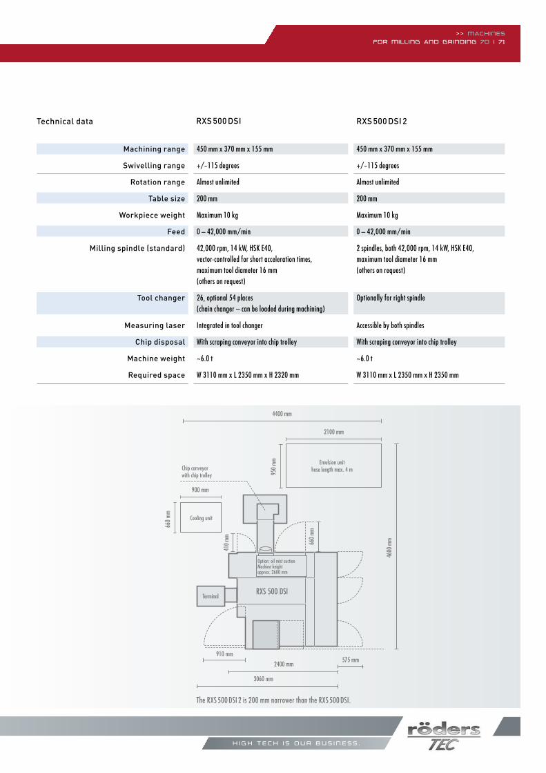
The RXS 500 DSI 2 is 200 mm narrower than the RXS 500 DSI.
RXS 500 DSI RXS 500 DSI 2
450 mm x 370 mm x 155 mm
+/-115 degrees
Almost unlimited
200 mm
Maximum 10 kg
0 – 42,000 mm/min
2 spindles, both 42,000 rpm, 14 kW, HSk e40, maximum tool diameter 16 mm (others on request)
Optionally for right spindle
Accessible by both spindles
With scraping conveyor into chip trolley
~6.0 t
W 3110 mm x L 2350 mm x H 2350 mm
450 mm x 370 mm x 155 mm
+/-115 degrees
Almost unlimited
200 mm
Maximum 10 kg
0 – 42,000 mm/min
42,000 rpm, 14 kW, HSk e40,vector-controlled for short acceleration times, maximum tool diameter 16 mm (others on request)
26, optional 54 places (chain changer – can be loaded during machining)
Integrated in tool changer
With scraping conveyor into chip trolley
~6.0 t
W 3110 mm x L 2350 mm x H 2320 mm
Terminal
660
mm
RXS 500 DSI
Maschinenfüße
0 1 m
4600
mm
Kühlaggregat
Späneförderermit Spänewagen
OptionÖlnebelabsaugungMaschinenhöhe ca. 2600 mm
Option Kabinenspülung
Option EmulsionsanlageSchlauchlänge max. 4 m
660
mm
910 mm575 mm
4400 mm
RXS 500 DSI
410
mm
900 mm
2100 mm
660
mm
950
mm
Maschinenfüße
0 1 m
Terminal
660 mm
930 mm
2400 mm
3060 mm
4600
mm
5300
mm Chip conveyor
with chip trolley
Option: oil mist suctionMachine heightapprox. 2600 mm
Emulsion unithose length max. 4 m
910 mm575 mm
2400 mm
3060 mm
Cooling unit
900 mm
660
mm
410
mm
4400 mm
2100 mm
950
mm
The Machine Concept of the RHP Series
>> www.roeders.de
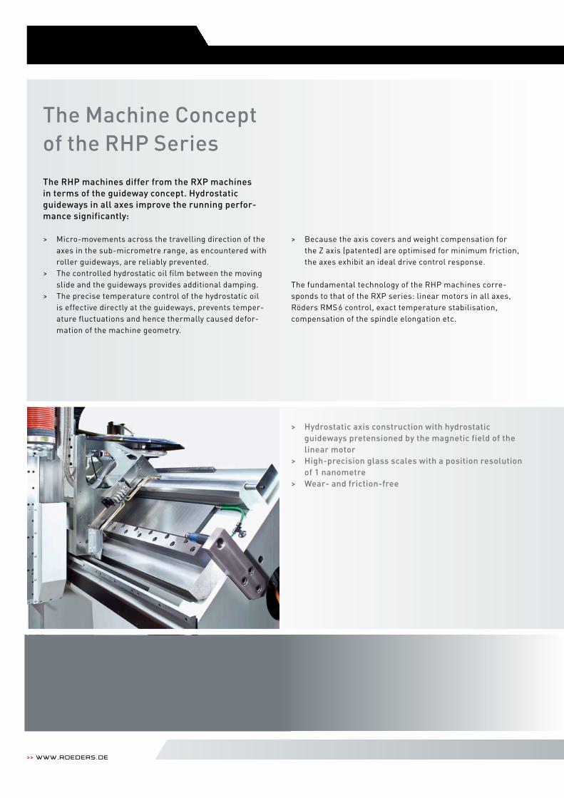
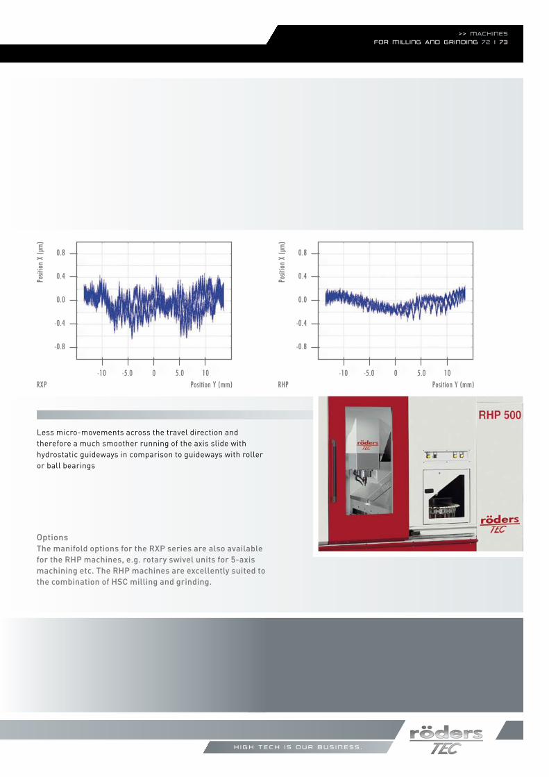
The RHP machines differ from the RXP machinesin terms of the guideway concept. Hydrostatic guideways in all axes improve the running perfor-mance significantly:
> Micro-movements across the travelling direction of the axes in the sub-micrometre range, as encountered with roller guideways, are reliably prevented.> The controlled hydrostatic oil film between the moving slide and the guideways provides additional damping.> The precise temperature control of the hydrostatic oil is effective directly at the guideways, prevents temper- ature fluctuations and hence thermally caused defor- mation of the machine geometry.
> Because the axis covers and weight compensation for the Z axis (patented) are optimised for minimum friction, the axes exhibit an ideal drive control response.
The fundamental technology of the RHP machines corre-sponds to that of the RXP series: linear motors in all axes, Röders RMS6 control, exact temperature stabilisation, compensation of the spindle elongation etc.
> Hydrostatic axis construction with hydrostatic guideways pretensioned by the magnetic field of the linear motor> High-precision glass scales with a position resolution of 1 nanometre> Wear- and friction-free
h i g h t e c h i s o u r b u s i n e s s .
>> Machinesfor Milling and grinding 72 | 73
OptionsThe manifold options for the RXP series are also available for the RHP machines, e.g. rotary swivel units for 5-axis machining etc. The RHP machines are excellently suited to the combination of HSC milling and grinding.
Posit
ion
X (µ
m)
Position Y (mm)
0.8
0.4
0.0
-0.4
-0.8
-10 -5.0 0 5.0 10
Posit
ion
X (µ
m)
Position Y (mm)
0.8
0.4
0.0
-0.4
-0.8
-10 -5.0 0 5.0 10
Less micro-movements across the travel direction and therefore a much smoother running of the axis slide with hydrostatic guideways in comparison to guideways with roller or ball bearings
RXP RHP
>> www.roeders.de
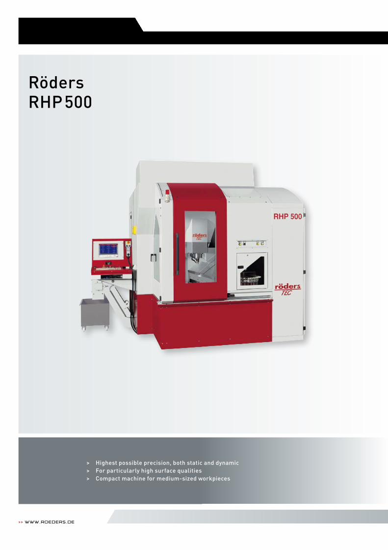
> Highest possible precision, both static and dynamic> For particularly high surface qualities > Compact machine for medium-sized workpieces
RödersRHP500

>> Machinesfor Milling and grinding 74 | 75
h i g h t e c h i s o u r b u s i n e s s .
Machining range
Table size
Maximum height
Workpiece weight
Feed
Milling spindle (standard)
Tool changer
Chip disposal
Machine weight
Required space
500 mm x 552 mm x 300 mm
600 mm x 540 mm
455 mm, between spindle nose and machine table
Maximum 400 kg
0 – 60,000 mm/min
42,000 rpm, 14 kW, HSk e40, maximum tool diameter 16 mm (others on request)
42 places (chain changer – can be loaded during machining) integrated measuring laser
With 2 screws into chip box behind the machine,additional chip conveyor optional
~10.0 t
W 3015 mm x L 2510 mm x H 2750 mm
Technical data
Chip
trolle
y
2450
mm
4320
mm
2320 mm
3455 mm
RHP 500
0 1 m
Oil mist suctionCooling unit
Cooling unit(hydraulics)
Terminal
632 mm
Chip conveyor

>> www.roeders.de
> Low version of RHP500 for relatively low work pieces> Low bridge and short Z-axis reduce deviations due to very short leverage between cutter and guideways> Highest precision and surface quality in 3-axis machining
RödersRHP500L
Image similar
>> Machinesfor Milling and grinding 76 | 77
h i g h t e c h i s o u r b u s i n e s s .
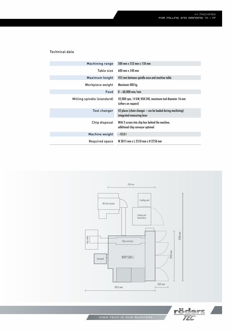
Machining range
Table size
Maximum height
Workpiece weight
Feed
Milling spindle (standard)
Tool changer
Chip disposal
Machine weight
Required space
Technical data
500 mm x 552 mm x 150 mm
600 mm x 540 mm
455 mm between spindle nose and machine table
Maximum 400 kg
0 – 60,000 mm/min
42,000 rpm, 14 kW, HSk e40, maximum tool diameter 16 mm (others on request)
42 places (chain changer – can be loaded during machining) integrated measuring laser
With 2 screws into chip box behind the machine,additional chip conveyor optional
~10.0 t
W 3015 mm x L 2510 mm x H 2750 mm
Chip
trolle
y
2450
mm
4320
mm
2320 mm
3455 mm
RHP 500 L
0 1 m
Oil mist suctionCooling unit
Cooling unit(hydraulics)
Terminal
632 mm
Chip conveyor

>> www.roeders.de

>> Röders worldwide
Highly efficient service and short reaction times are guaranteed by Röders through well-trained local technicians. In the USA, China, France and Vietnam Röders is represented by its own subsidiaries.
In many other countries, Röders maintains longstanding partnerships with renowned companies for local service.
h i g h t e c h i s o u r b u s i n e s s .
Röders GmbHScheibenstr. 6 / 29614 Soltau / GermanyTel. +49 5191-603-43, Fax +49 5191-603-38E-Mail [email protected] / www.roeders.de
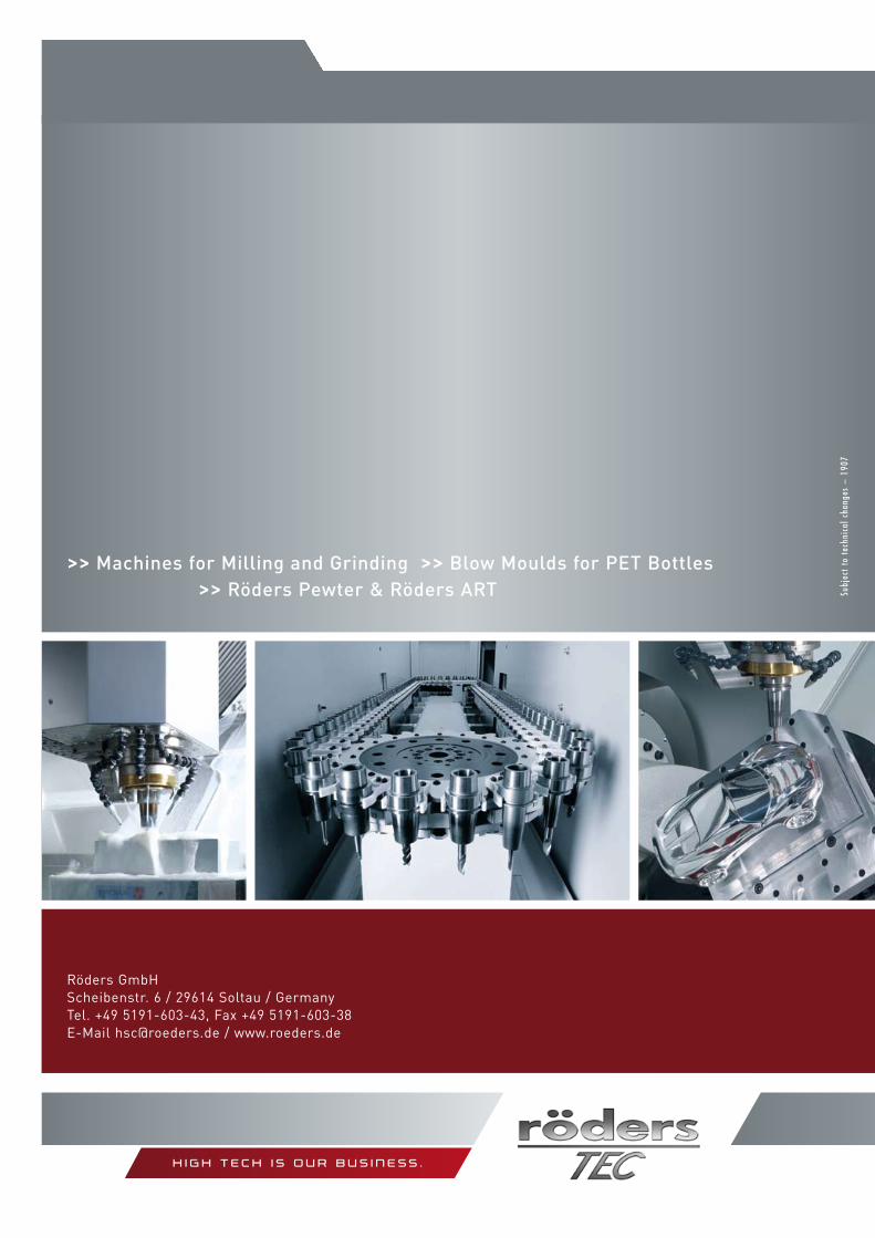
>> Machines for Milling and Grinding >> Blow Moulds for PET Bottles >> Röders Pewter & Röders ART
h i g h t e c h i s o u r b u s i n e s s .
Subj
ect
to t
echn
ical
cha
nges
– 1
907


![Metalworking] Milling Grinding Drilling](https://img.pdfslide.net/doc/110x75/577d36861a28ab3a6b93563a/metalworking-milling-grinding-drilling.jpg)