Embed Size (px)
Citation preview
MachMotion IO6 V.3 Breakout Board Manual
(with Parallel Port)
Version 3.0 Released 06/01/09 14518 County Road 7240 Newburg, MO 65550
www.machmotion.com

**************WARNING**************
Improper installation of this motion control interface can cause DEATH, INJURY or serious PROPERTY DAMAGE. Do not attempt to install this
board unless you are a properly qualified electrical engineer and system integrator. Not every detail of the installation is included here. A
familiarity with electronic circuits, power circuits, and the MACH3 control is a pre-requisite to knowing how to install or use this equipment.
**************WARNING*************
1
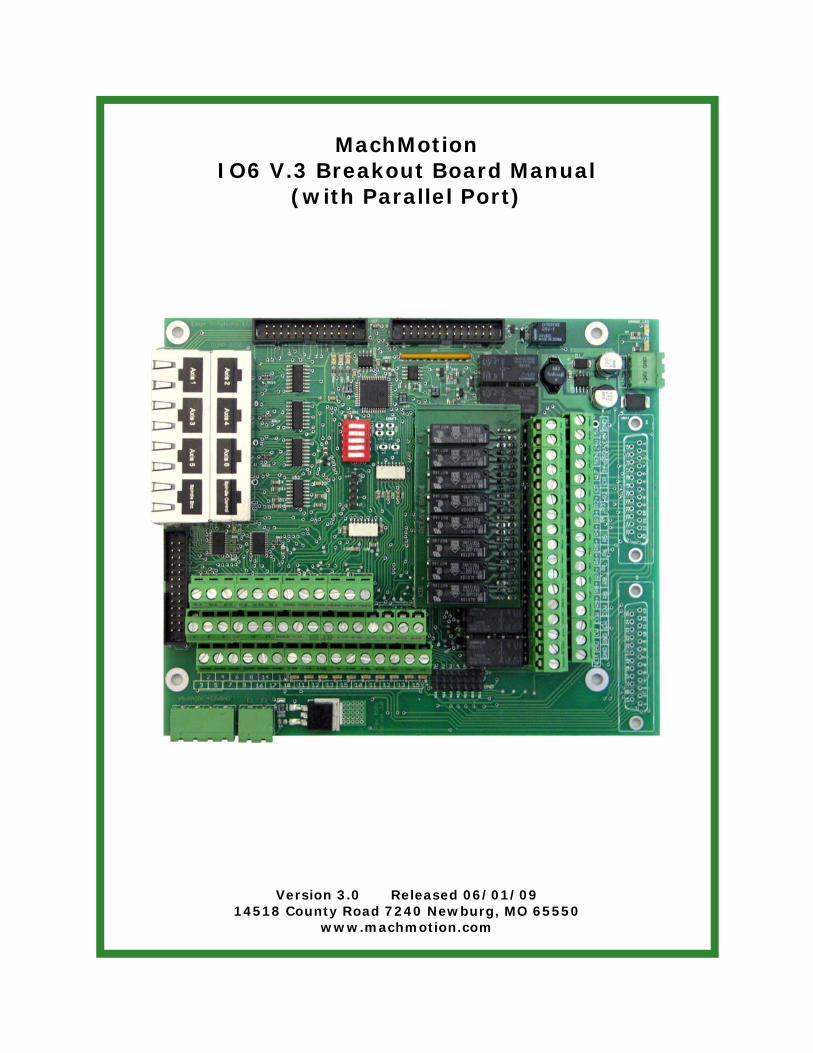
Table of Contents MachMotion IO6 Layout .................................................................... 3
IO6 General Description ................................................................... 4
Features .......................................................................................... 4
Input & Output List ........................................................................... 4
Use of this manual ............................................................................ 4
IO6 System Requirements ................................................................ 4
2 PC Parallel ports ............................................................................ 4
Power Requirements ......................................................................... 4
Description of the interface assemblies ............................................ 5
2. Digital (pulse and direction) Interface for 6 axis motion control ....... 6
a. Differential step and direction interface ........................................................... 6
3. Spindle Control Overview ........................................................... 7
4. IO6 CW and CCW relay outputs ................................................... 8
5. I06 analog spindle voltage output ................................................ 8
6. Configuring the 0-10V analog output ........................................... 8
7. I06 Inputs for measuring spindle RPM .......................................... 9
9. Opto-Isolated digital inputs terminals ......................................... 10
1. +24 v Limit Switch Input .......................................................................................................... 12
2. Opto sensor input ................................................................................................................... 12
3. PNP Proximity Sensor .............................................................................................................. 12
4. Opto sensor input ................................................................................................................... 12
5. NPN Proxy Switch +5v only. .................................................................................................... 13
6. Drive error (+5v input)+5v signal input ................................................................................... 13
7. +5V Signal input ...................................................................................................................... 14
8. +24 signal input ....................................................................................................................... 14
9. Digitizing Probe Input ................................................................................. 15
11. Digitizing probe input terminal .................................................. 16
12. Estop terminals ....................................................................... 16
2
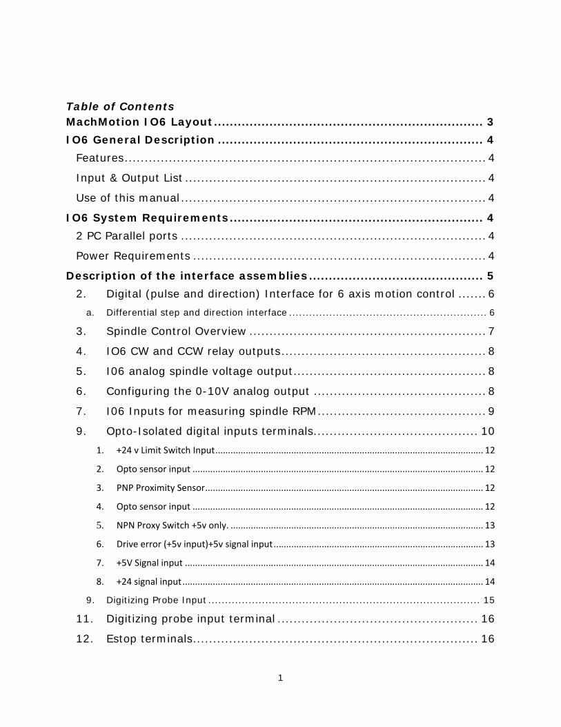
13. Error Input ............................................................................. 16
14. Very high speed opto-isolated inputs ......................................... 16
15. Relay inputs and outputs .......................................................... 17
Relay Input Configuration (See page 3) ......................................... 18
Relay Out-put Configuration (See page 3) ...................................... 19
Mod-Jack Pin-outs .......................................................................... 21
3
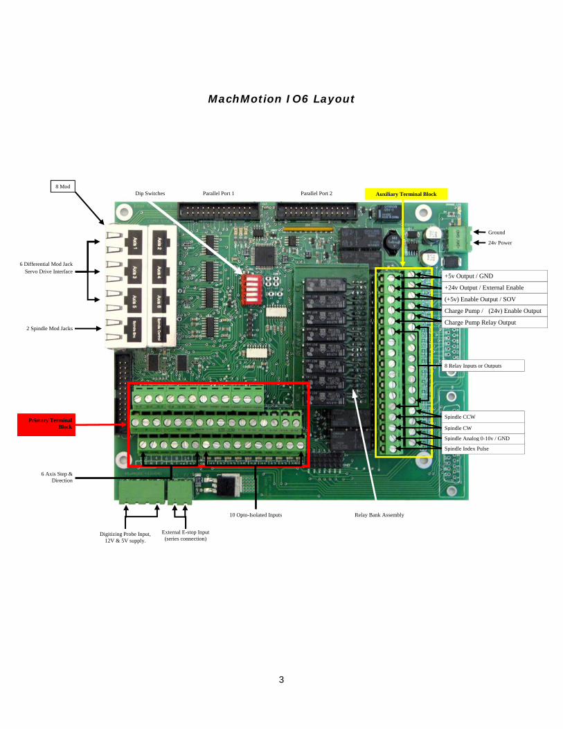
MachMotion IO6 Layout
2 Spindle Mod Jacks
Dip Switches
10 Opto-Isolated Inputs Relay Bank Assembly
6 Axis Step & Direction
54321
6 Differential Mod Jack Servo Drive Interface
Parallel Port 1 Parallel Port 2
Primary Terminal Block
Auxiliary Terminal Block 8 Mod
Digitizing Probe Input, 12V & 5V supply.
External E-stop Input (series connection)
Ground
24v Power
Spindle Index Pulse
Spindle Analog 0-10v / GND
8 Relay Inputs or Outputs
Spindle CW
Spindle CCW
+24v Output / External Enable
+5v Output / GND
Charge Pump / (24v) Enable Output
Charge Pump Relay Output
(+5v) Enable Output / SOV
4
IO6 General Description MachMotion’s IO6 Breakout Board provides a flexible, plug-in-play interface and functions for CNC Controls using PC Based Parallel Port Control Software. Cabling to the servo drives, and spindle relay outputs employ RJ45 mod jack connectors and Phoenix screw terminals for flexibility.
Features • Single supply power: unregulated 24vdc • Digital differential and single ended TTL (Pulse and Direction) interfaces for motion control
for up to six axis. • Outputs: 2 Amp bare relay contacts. • Opto-Isolated inputs. • Complete spindle speed control circuitry and spindle feedback. • Charge Pump safety circuit integrated to control all outputs. • On board Switching +5v regulated power supply. • Drive Enable can be configured at 5v, 24v, GND, or a user supplied voltage. • Total of 34 I/O.
Input & Output List • 12 - Outputs generally used for step and direction outputs for 6 axis. If less than six axis
are to be controlled, some of these 12 outputs can be used for general purpose outputs. • 10 - Inputs (1 input is typically used for Spindle Encoder Input).These inputs can be
jumpered for 5v input, 12-24 v inputs, PNP or NPN sensors. • 8 - 2 Amp Relay I/O’s which can be configured as either inputs or outputs. • 2 - Spindle Relay Outputs. • 1 - Analog Output 0-10V. • 3 - Charge Pump Outputs. • E-stop configurations provided. • Digitizing probe sensing and 12v probe supply interface provided.
Use of this manual This Manual explains the functions of the IO6 in a logical progression. To understand how to safely connect and use the IO6, it is important that the system integrator read and understand the manual in its entirety before attempting to set up and use this I/O board.
IO6 System Requirements
2 PC Parallel ports
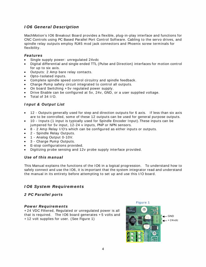
Power Requirements +24 VDC Filtered, Regulated or unregulated power is all that is required. The IO6 board generates +5 volts and +12 volt supplies for user. (See Figure 1)
Figure 1
+24vdc
GND
5
Description of the interface assemblies
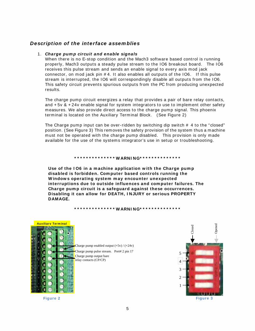
1. Charge pump circuit and enable signals When there is no E-stop condition and the Mach3 software based control is running properly, Mach3 outputs a steady pulse stream to the IO6 breakout board. The IO6 receives this pulse stream and sends an enable signal to every axis mod jack connector, on mod jack pin #4. It also enables all outputs of the IO6. If this pulse stream is interrupted, the IO6 will correspondingly disable all outputs from the IO6. This safety circuit prevents spurious outputs from the PC from producing unexpected results. The charge pump circuit energizes a relay that provides a pair of bare relay contacts, and +5v & +24v enable signal for system integrators to use to implement other safety measures. We also provide direct access to the charge pump signal. This phoenix terminal is located on the Auxiliary Terminal Block. (See Figure 2) The Charge pump input can be over-ridden by switching dip switch # 4 to the “closed” position. (See Figure 3) This removes the safety provision of the system thus a machine must not be operated with the charge pump disabled. This provision is only made available for the use of the systems integrator’s use in setup or troubleshooting.
**************WARNING**************
Use of the IO6 in a machine application with the Charge pump disabled is forbidden. Computer based controls running the Windows operating system may encounter unexpected interruptions due to outside influences and computer failures. The Charge pump circuit is a safeguard against these occurrences. Disabling it can allow for DEATH, INJURY or serious PROPERTY DAMAGE.
**************WARNING**************
Figure 3
Clo
sed
Ope
ned
5
4
3
2
1
Figure 2
Charge pump output bare relay contacts (CP/CP)
Auxiliary Terminal
Charge pump pulse stream. Port# 2 pin 17
Charge pump enabled output (+5v) / (+24v)
6
2. Digital (pulse and direction) Interface for 6 axis motion control
The IO6 breakout board provides differential and single ended step and direction both of which may be employed at the same time.
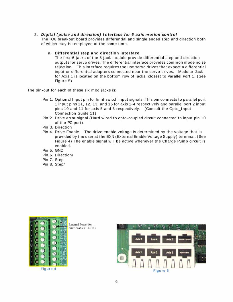
a. Differential step and direction interface The first 6 jacks of the 8 jack module provide differential step and direction outputs for servo drives. The differential interface provides common mode noise rejection. This interface requires the use servo drives that expect a differential input or differential adapters connected near the servo drives. Modular Jack for Axis 1 is located on the bottom row of jacks, closest to Parallel Port 1. (See Figure 5)
The pin-out for each of these six mod jacks is:
Pin 1. Optional Input pin for limit switch input signals. This pin connects to parallel port 1 input pins 11, 12, 13, and 15 for axis 1-4 respectively and parallel port 2 input pins 10 and 11 for axis 5 and 6 respectively. (Consult the Opto_Input Connection Guide 11)
Pin 2. Drive error signal (Hard wired to opto-coupled circuit connected to input pin 10 of the PC port).
Pin 3. Direction Pin 4. Drive Enable. The drive enable voltage is determined by the voltage that is
provided by the user at the EXN (External Enable Voltage Supply) terminal. (See Figure 4) The enable signal will be active whenever the Charge Pump circuit is enabled.
Pin 5. GND Pin 6. Direction/ Pin 7. Step Pin 8. Step/
External Power for drive enable (EX-EN)
Figure 4 Figure 5
7
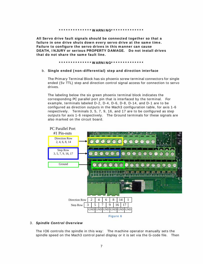
b. Single ended (non-differential) step and direction interface The Primary Terminal Block has six phoenix screw terminal connectors for single ended (5v TTL) step and direction control signal access for connection to servo drives. The labeling below the six green phoenix terminal block indicates the corresponding PC parallel port pin that is interfaced by the terminal. For example, terminals labeled D-2, D-4, D-6, D-8, D-14, and D-1 are to be configured as direction outputs in the Mach3 configuration table, for axis 1-6 respectively. Terminals 3, 5, 7, 9, 16, and 17 are to be configured as step outputs for axis 1-6 respectively. The Ground terminals for these signals are also marked on the circuit board.
3. Spindle Control Overview The IO6 controls the spindle in this way: The machine operator manually sets the spindle speed on the Mach3 control panel display or it is set via the G-code file. Then
**************WARNING************** All Servo drive fault signals should be connected together so that a failure in one drive shuts down every servo drive at the same time. Failure to configure the servo drives in this manner can cause DEATH, INJURY or serious PROPERTY DAMAGE. Do not install drives that do not share the same fault line.
**************WARNING**************
Direction Row 2, 4, 6, 8, 14
Step Row 3, 5, 7, 9, 16, 17
Ground
PC Parallel Port #1 Pin-outs
2 4 6 8 14 1 3 5 7 9 16 17
GND GND GND GND GND GNDStep Row
Direction Row
Figure 6
8
either the appropriate M-code or the operator turns on the spindle with the “button” on the control screen. The hardware control sequence is as follows: The Mach3 control turns on either a CW or CCW relay. Then the IO6 sends an appropriate 0-10 volt analog signal out to the Variable Frequency Drive (VFD) which controls the spindle motor speed. Finally, the Mach3 control measures and monitors the Spindle RPM by measuring the pulse rate of a pulse stream that it receives through the IO6 from a sensor or encoder mounted on the spindle, and displays the RPM on the Mach3 control panel display. Interfacing the Spindle is accomplished either through the two mod jack connectors 7 and 8 or through Phoenix screw terminal connections to the IO6. For convenience, the mod jack connections are preferred, and will be discussed first in this section. All of the signals mentioned and used in the mod jack connections correspond to the connections that can be made using the screw terminal connections.
4. IO6 CW and CCW relay outputs Mod Jack #8 of the 8 mod. Jack module is dedicated to spindle output signals. See page 6 Figure 5. All of the connections to the mod jack are also available on phoenix screw terminals (See page 7 Figure 6), but mod jack connections are made available for convenience. The relay contacts are rated at 1 amp 115 VAC, and 3 amps at 30 VDC. These relay contacts can be connected to turn on a power contactor for the spindle motor or for VFD inputs to control direction of rotation. The pin-out of mod jack # 8 are as follows: Pin 1 0-10 VDC analog signal for VFD spindle speed control. Pin 2 CW spindle dry relay contact. Pin 3 CW spindle dry relay contact. Pin 4 Enable - voltage provided at external enable voltage supply (EXN) This will be the same as terminal SOV on the Auxiliary Terminal Block. Pin 5 GND (for analog voltage on pin 1 and the enable voltage. Pin 6 No Connection. Pin 7 CCW spindle dry relay contact. Pin 8 CCW spindle dry relay contact.
5. I06 analog spindle voltage output The Mach3 control software program provides a variable frequency pulse output on a step signal line which is scalable through the configuration menus in Mach3. This signal is converted to a proportional analog 0-10 volt signal which is typically used to control the speed of Variable Frequency Drives (AKA inverters). The hardware on the IO6 board performs this conversion. The setup to implement this function is configured in the Mach3 configuration tables. The setup procedure is provided below.
6. Configuring the 0-10V analog output 1. In Mach3 Go to Config / Ports&Pins / Motor Outputs. Enable the spindle and set the
step pin to 1. and step port to 2 Set the DIR pin to 14 and Port2. 3. Go to Config / Ports&Pins / Spindle setup / motor control. Check the box for “Use
Spindle Motor Output” and check the box for Step /Dir Motor.
9
4. Go to Config / Ports&Pins / Spindle Setup / Relay Output. Enter “1” for M3 output # and “1” for M4 output #.
5. Go to Config / Motor Tuning / Spindle. On Steps per unit put 1,500, for velocity move the slider all the way to the maximum. For Acceleration, choose the acceleration that you feel comfortable with. The acceleration set here must be within the range of the VFD acceleration setup if a VFD is used. Mach3 will then produce the appropriate voltage for speeds less than the maximum.
7. I06 Inputs for measuring spindle RPM
The IO6 provides interfaces for receiving a pulse stream from a sensor configured to a rotating spindle, which is used to measure the RPM of the spindle. The IO6 provides for three different methods of receiving this pulse stream. The IO6 also includes a pulse stretching circuit which sends a 9 us pulse to the CNC control for any length input pulse received by an encoder or photo interrupter sensor configured on the spindle. This pulse stretching circuit ensures that the MACH3 control will not miss any pulses. An incremental encoder, providing the usual 5 volt A, A/ B, B/, I, and I/ differential signals can be used to sense spindle RPM. Using differential signals provides common mode noise reduction for reliable pulse monitoring. Modular Jack #7 (located on the lower layer of the 8 jack module, and close to the Dip Switches) is provided for a convenient differential spindle feedback connection to the IO6. Obviously, to utilize these noise immune inputs, a differential encoder driver or differential encoder must be mounted on the spindle, and connected to the cable with the CAT5 mod jack connection for mating to the IO6 board. The system integrator may choose to select only the index pulse provided by an encoder mounted on the spindle, or all of the encoder signals (A, B, and I) provided by using the Dip Switch settings below. The use of the A and B encoder inputs may be useful in applications where the exact rotational position of the spindle is needed. Normally, MACH3 derives spindle speed from one incoming pulse such as the index pulse. Alternatively, a photo interrupter sensor, inductive sensor or other sensor can be configured to produce one pulse per revolution of the spindle. The signal can be converted near the sensor to differential through the use of a converter such as the MachMotion’s R2210 converter and then interfaced to the IO6 through a shielded CAT5 cable and Mod Jack #7 mentioned in the previous paragraph. The inputs to this mod jack are expected to be based on 5v differential signals, as are provided by a 26C31 Differential driver. The pin out of Mod Jack #7 is provided: Pin 1 Encoder A Pin 2 Encoder A/ Pin 3 Encoder B Pin 4 +5v to power the encoder Pin 5 GND Pin 6 Encoder B/ Pin 7 Encoder I Pin 8 Encoder I/ Both spindle RPM monitoring signals and Spindle speed control output signals can be connected to the IO6 board through the mod jacks as mentioned above. The speed measuring signal can also be a single ended opto-isolated signal connected to the
10
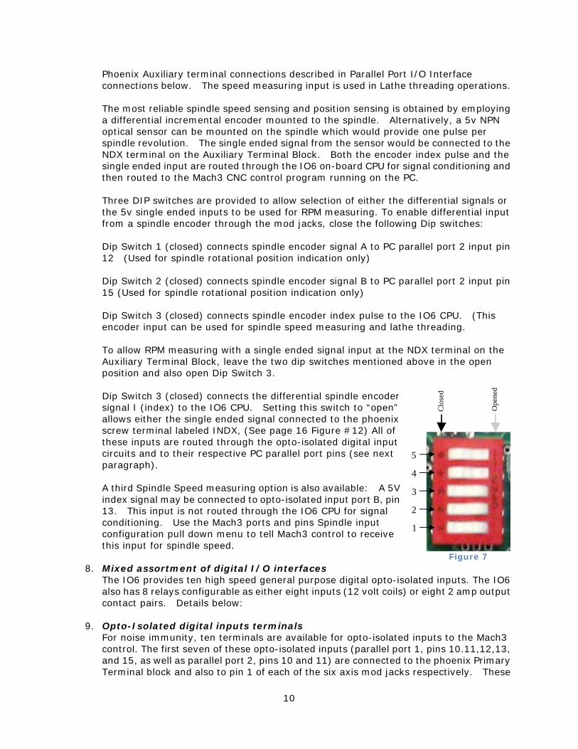
Phoenix Auxiliary terminal connections described in Parallel Port I/O Interface connections below. The speed measuring input is used in Lathe threading operations. The most reliable spindle speed sensing and position sensing is obtained by employing a differential incremental encoder mounted to the spindle. Alternatively, a 5v NPN optical sensor can be mounted on the spindle which would provide one pulse per spindle revolution. The single ended signal from the sensor would be connected to the NDX terminal on the Auxiliary Terminal Block. Both the encoder index pulse and the single ended input are routed through the IO6 on-board CPU for signal conditioning and then routed to the Mach3 CNC control program running on the PC. Three DIP switches are provided to allow selection of either the differential signals or the 5v single ended inputs to be used for RPM measuring. To enable differential input from a spindle encoder through the mod jacks, close the following Dip switches: Dip Switch 1 (closed) connects spindle encoder signal A to PC parallel port 2 input pin 12 (Used for spindle rotational position indication only) Dip Switch 2 (closed) connects spindle encoder signal B to PC parallel port 2 input pin 15 (Used for spindle rotational position indication only) Dip Switch 3 (closed) connects spindle encoder index pulse to the IO6 CPU. (This encoder input can be used for spindle speed measuring and lathe threading. To allow RPM measuring with a single ended signal input at the NDX terminal on the Auxiliary Terminal Block, leave the two dip switches mentioned above in the open position and also open Dip Switch 3. Dip Switch 3 (closed) connects the differential spindle encoder signal I (index) to the IO6 CPU. Setting this switch to “open” allows either the single ended signal connected to the phoenix screw terminal labeled INDX, (See page 16 Figure #12) All of these inputs are routed through the opto-isolated digital input circuits and to their respective PC parallel port pins (see next paragraph). A third Spindle Speed measuring option is also available: A 5V index signal may be connected to opto-isolated input port B, pin 13. This input is not routed through the IO6 CPU for signal conditioning. Use the Mach3 ports and pins Spindle input configuration pull down menu to tell Mach3 control to receive this input for spindle speed.
8. Mixed assortment of digital I/O interfaces The IO6 provides ten high speed general purpose digital opto-isolated inputs. The IO6 also has 8 relays configurable as either eight inputs (12 volt coils) or eight 2 amp output contact pairs. Details below:
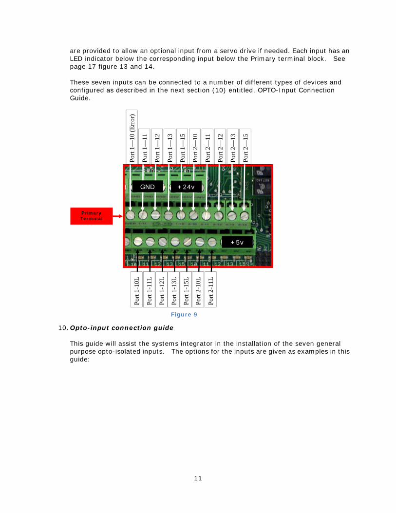
9. Opto-Isolated digital inputs terminals For noise immunity, ten terminals are available for opto-isolated inputs to the Mach3 control. The first seven of these opto-isolated inputs (parallel port 1, pins 10.11,12,13, and 15, as well as parallel port 2, pins 10 and 11) are connected to the phoenix Primary Terminal block and also to pin 1 of each of the six axis mod jacks respectively. These
Clo
sed
Ope
ned
5
3
2
1
4
Figure 7
11
Figure 9
are provided to allow an optional input from a servo drive if needed. Each input has an LED indicator below the corresponding input below the Primary terminal block. See page 17 figure 13 and 14. These seven inputs can be connected to a number of different types of devices and configured as described in the next section (10) entitled, OPTO-Input Connection Guide.
10. Opto-input connection guide This guide will assist the systems integrator in the installation of the seven general purpose opto-isolated inputs. The options for the inputs are given as examples in this guide:
Primary Terminal
+24v GND
+5v
Port
1—11
Port
1—13
Port
1—12
Port
1—10
(Err
or)
Port
2—10
Port
2—11
Port
2—12
Port
1—15
Port
2—13
Port
2—15
Port
1-11
L
Port
1-13
L
Port
1-12
L
Port
1-10
L
Port
2-10
L
Port
2-11
L
Port
1-15
L
12
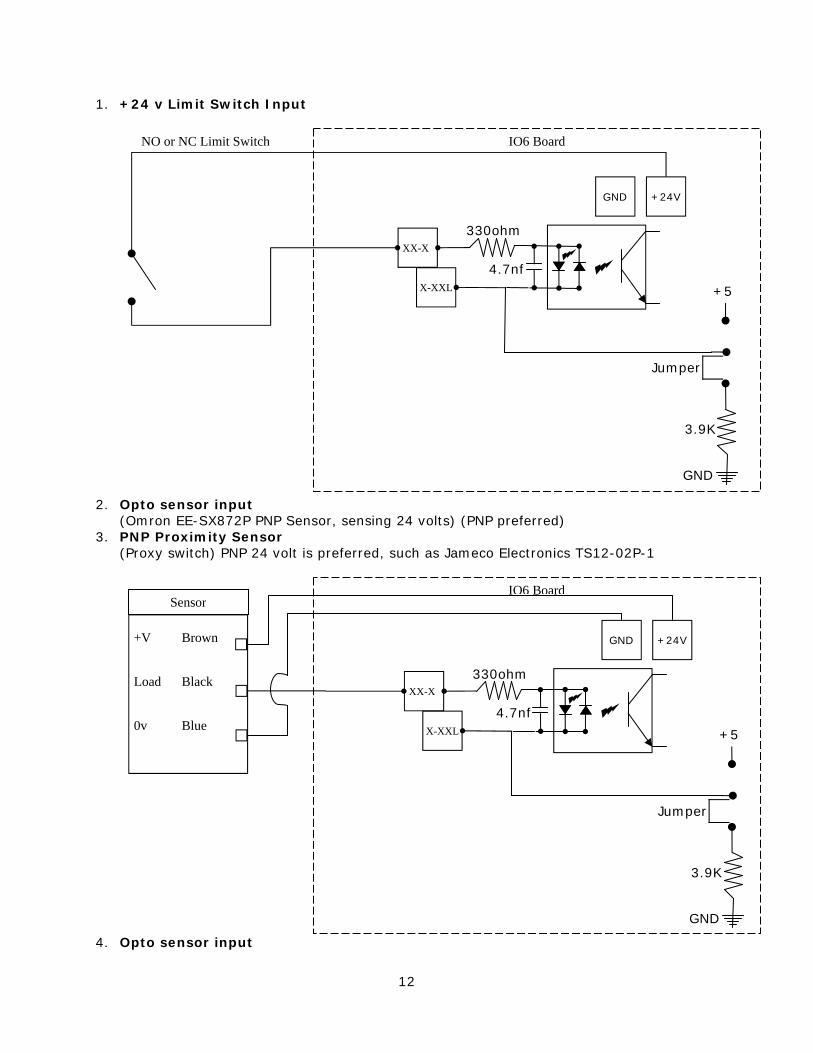
1. +24 v Limit Switch Input
2. Opto sensor input
(Omron EE-SX872P PNP Sensor, sensing 24 volts) (PNP preferred) 3. PNP Proximity Sensor
(Proxy switch) PNP 24 volt is preferred, such as Jameco Electronics TS12-02P-1
4. Opto sensor input
+V Brown
0v Blue
Load Black
+24V GND
X-XXL +5
330ohm
3.9K
GND
Jumper
4.7nf
XX-X
Sensor IO6 Board
+24V GND
X-XXL +5
330ohm
3.9K
GND
Jumper
4.7nf
XX-X
NO or NC Limit Switch IO6 Board
13
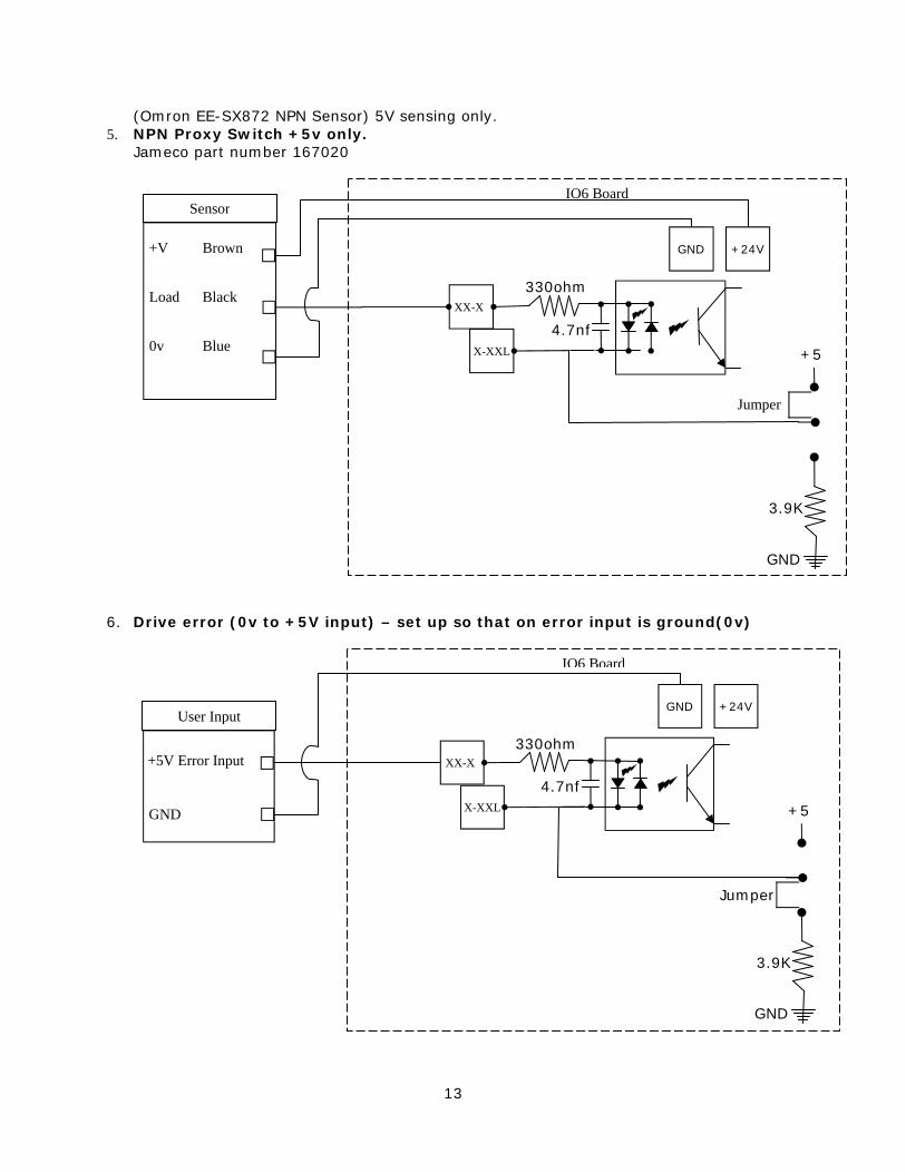
(Omron EE-SX872 NPN Sensor) 5V sensing only. 5. NPN Proxy Switch +5v only.
Jameco part number 167020
6. Drive error (0v to +5V input) – set up so that on error input is ground(0v)
+24V GND
X-XXL +5
330ohm
3.9K
GND
Jumper
4.7nf
XX-X
IO6 Board
GND
+5V Error Input
User Input
+V Brown
0v Blue
Load Black
Sensor
+24V GND
X-XXL +5
330ohm
3.9K
GND
Jumper
4.7nf
XX-X
IO6 Board
14
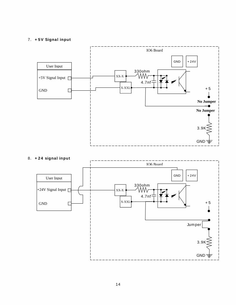
7. +5V Signal input
8. +24 signal input
+24V GND
X-XXL +5
330ohm
3.9K
GND
Jumper
4.7nf
XX-X
IO6 Board
GND
+24V Signal Input
User Input
+24V GND
X-XXL +5
330ohm
3.9K
GND
No Jumper
4.7nf
XX-X
IO6 Board
GND
+5V Signal Input
User Input
No Jumper
15
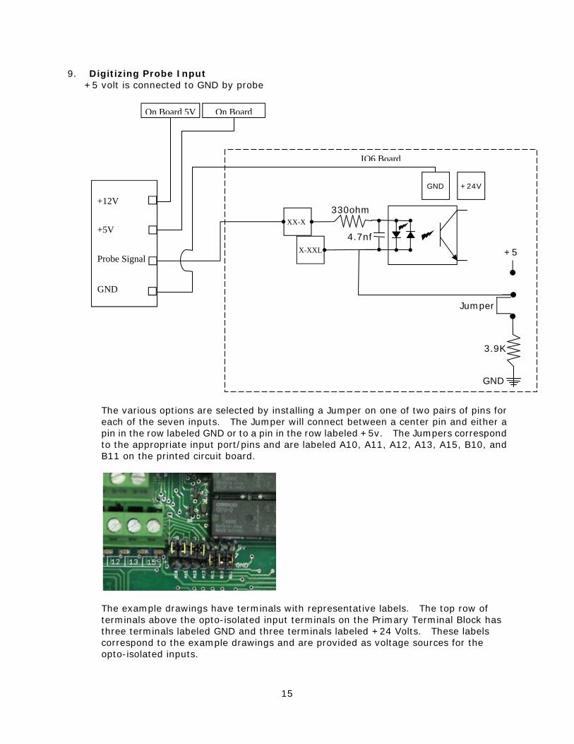
9. Digitizing Probe Input +5 volt is connected to GND by probe
The various options are selected by installing a Jumper on one of two pairs of pins for each of the seven inputs. The Jumper will connect between a center pin and either a pin in the row labeled GND or to a pin in the row labeled +5v. The Jumpers correspond to the appropriate input port/pins and are labeled A10, A11, A12, A13, A15, B10, and B11 on the printed circuit board.
The example drawings have terminals with representative labels. The top row of terminals above the opto-isolated input terminals on the Primary Terminal Block has three terminals labeled GND and three terminals labeled +24 Volts. These labels correspond to the example drawings and are provided as voltage sources for the opto-isolated inputs.
+24V GND
X-XXL +5
330ohm
3.9K
GND
Jumper
4.7nf
XX-X
IO6 Board
Probe Signal
+5V
GND
+12V
On Board On Board 5V
16
The example drawings in the Opto-Input Connection Guide show the middle row of terminals in the Primary Terminal Block labeled as X-XX. These connections in the guide correspond to terminals labeled 1-10, 1-11, 1-12 etc. The example drawings show the lower level of terminals labeled X-XXL. These terminals are located at the circuit board level. and are labeled 1-10L, 1-11L, 2-10L on the Primary Terminal Block.
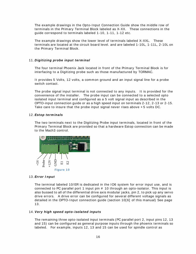
11. Digitizing probe input terminal
The four terminal Phoenix Jack located in front of the Primary Terminal Block is for interfacing to a Digitizing probe such as those manufactured by TORMAC. It provides 5 Volts, 12 volts, a common ground and an input signal line for a probe switch contact. The probe signal input terminal is not connected to any inputs. It is provided for the convenience of the installer. The probe input can be connected to a selected opto isolated input terminal and configured as a 5 volt signal input as described in the OPTO-input connection guide or as a high speed input on terminals 2-12, 2-13 or 2-15. Take care to insure that the probe input signal never rises above +5 volts DC.
12. Estop terminals The two terminals next to the Digitizing Probe input terminals, located in front of the Primary Terminal Block are provided so that a hardware Estop connection can be made to the Mach3 control.
13. Error Input
The terminal labeled 10/ER is dedicated in the IO6 system for error input use, and is connected to PC parallel port 1 input pin # 10 through an opto-isolator. This input is also bussed to all of the differential drive axis modular jacks, pin 2, to pick up any servo drive errors. A drive error can be configured for several different voltage signals as detailed in the OPTO-Input connection guide (section 10[6] of this manual) See page 13.
14. Very high speed opto-isolated inputs The remaining three opto-isolated input terminals (PC parallel port 2, input pins 12, 13 and 15) can be configured as general purpose inputs through the phoenix terminals so labeled. For example, inputs 12, 13 and 15 can be used for spindle control as
Figure 10
+5V
GN
D
Prob
e
+12V
E1
E2
17
described under the section of this manual entitled Spindle control. See the description of these features and the pertinent DIP switch settings in the paragraph entitled Spindle control above. See page 7 Figure #13. These three inputs are limited to 5v signal inputs and the three terminals below the input terminals of the Primary Terminal Block provide the 5v source if needed.
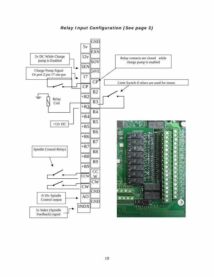
15. Relay inputs and outputs For noise immunity, the IO6 provides a PCB mounted bank of 8 relays which can be configured as either inputs or outputs. See page 15 Figure #11. The relay bank is switched between input and output modes by plugging the bank in the IO6 main circuit board in one of two physical positions on the circuit board. Two guide pins provide positive indicators for the two mounting positions. The connections to the Relay bank PCB are found on the Auxiliary Terminal Block. The output connections are labeled in pairs: +R2 R2, +R3 R3 etc. When the relay bank circuit board is plugged into the pair of receptacles closest to the double layer phoenix connector, it is configured as an output bank of relays. In this configuration, the output pairs become pairs of dry contacts capable of handling 2 amps each. To set up in Mach3 go to Config/Ports and Pins/Setup and Axis Selection, Port 2 configuration table, then deselect select pins 2-9 are inputs. When the relay bank circuit board is plugged into the pair of receptacles further away from the double layer phoenix connector, it is configured as an input bank of relays. In this case, the relay coil connections are applied to the R2-R9 pairs of connectors. To energize the relays, a set of dry switch contacts must be connected to the pair of terminals, since the coil voltage (24v) is already provided to the upper row of Phoenix terminals when in the input mode. Of course, Config/Ports and Pins/Setup and Axis Selection, Port 2 configuration table must be set to indicate that Port2, pins 2-9 are inputs and enabled.
18
Relay Input Configuration (See page 3)
Charge Pump Signal Or port 2 pin 17 out-put
+12v DC +R5
5v
5EN
17
CP
+R3
+R6
+R7
+R8
+R9
AO
CCW
CW
12v
+R4
+R2
R5
GND
SOV
24VE
CP
R3
R6
R7
R8
R9
GND
GND
CCW
CW
EXN
R4
R2Relay Coil
0-10v Spindle Control output
Limit Switch if relays are used for inputs
5v Index (Spindle Feedback) signal
Spindle Control Relays
5v DC While Charge pump is Enabled
Relay contacts are closed while charge pump is enabled
INDX
19
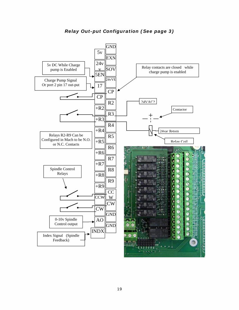
Relay Out-put Configuration (See page 3)
5v DC While Charge pump is Enabled
Charge Pump Signal Or port 2 pin 17 out-put
24VAC?
Relay Coil
Contactor
24vac Return Relays R2-R9 Can be
Configured in Mach to be N.O. or N.C. Contacts +R5
5v
5EN
17
CP
+R3
+R6
+R7
+R8
+R9
AO
INDX
CCW
CW
24vv
+R4
+R2
R5
GND
SOV
24vVE
CP
R3
R6
R7
R8
R9
GND
GND
CCW
CW
EXN
R4
R2
0-10v Spindle Control output
Index Signal (Spindle Feedback)
Spindle Control Relays
Relay contacts are closed while charge pump is enabled
20
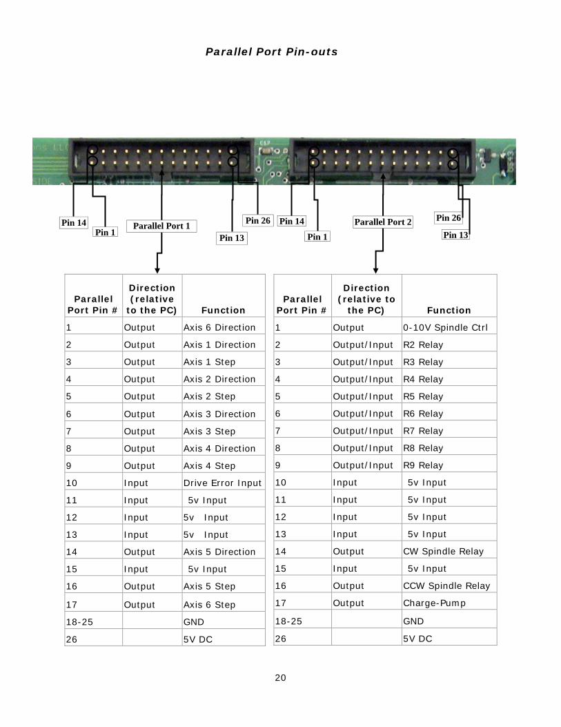
Parallel Port Pin #
Direction (relative
to the PC) Function
1 Output Axis 6 Direction
2 Output Axis 1 Direction
3 Output Axis 1 Step
4 Output Axis 2 Direction
5 Output Axis 2 Step
6 Output Axis 3 Direction
7 Output Axis 3 Step
8 Output Axis 4 Direction
9 Output Axis 4 Step
10 Input Drive Error Input
11 Input 5v Input
12 Input 5v Input
13 Input 5v Input
14 Output Axis 5 Direction
15 Input 5v Input
16 Output Axis 5 Step
17 Output Axis 6 Step
18-25 GND
26 5V DC
Parallel Port Pin #
Direction (relative to
the PC) Function
1 Output 0-10V Spindle Ctrl
2 Output/Input R2 Relay
3 Output/Input R3 Relay
4 Output/Input R4 Relay
5 Output/Input R5 Relay
6 Output/Input R6 Relay
7 Output/Input R7 Relay
8 Output/Input R8 Relay
9 Output/Input R9 Relay
10 Input 5v Input
11 Input 5v Input
12 Input 5v Input
13 Input 5v Input
14 Output CW Spindle Relay
15 Input 5v Input
16 Output CCW Spindle Relay
17 Output Charge-Pump
18-25 GND
26 5V DC
Parallel Port Pin-outs
Pin 26
Pin 13
Pin 14 Pin 1
Pin 26
Pin 13Pin 14
Pin 1Parallel Port 2
Parallel Port 1
21
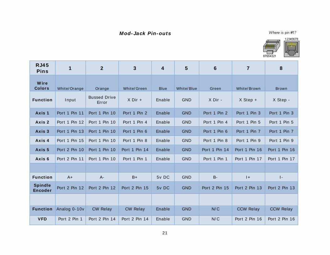
Mod-Jack Pin-outs
RJ45 Pins
1 2 3 4 5 6 7 8
Wire Colors White/Orange Orange White/Green Blue White/Blue Green White/Brown Brown
Function Input Bussed Drive
Error X Dir + Enable GND X Dir - X Step + X Step -
Axis 1 Port 1 Pin 11 Port 1 Pin 10 Port 1 Pin 2 Enable GND Port 1 Pin 2 Port 1 Pin 3 Port 1 Pin 3
Axis 2 Port 1 Pin 12 Port 1 Pin 10 Port 1 Pin 4 Enable GND Port 1 Pin 4 Port 1 Pin 5 Port 1 Pin 5
Axis 3 Port 1 Pin 13 Port 1 Pin 10 Port 1 Pin 6 Enable GND Port 1 Pin 6 Port 1 Pin 7 Port 1 Pin 7
Axis 4 Port 1 Pin 15 Port 1 Pin 10 Port 1 Pin 8 Enable GND Port 1 Pin 8 Port 1 Pin 9 Port 1 Pin 9
Axis 5 Port 2 Pin 10 Port 1 Pin 10 Port 1 Pin 14 Enable GND Port 1 Pin 14 Port 1 Pin 16 Port 1 Pin 16
Axis 6 Port 2 Pin 11 Port 1 Pin 10 Port 1 Pin 1 Enable GND Port 1 Pin 1 Port 1 Pin 17 Port 1 Pin 17
Function A+ A- B+ 5v DC GND B- I+ I-
Spindle Encoder
Port 2 Pin 12 Port 2 Pin 12 Port 2 Pin 15 5v DC GND Port 2 Pin 15 Port 2 Pin 13 Port 2 Pin 13
Function Analog 0-10v CW Relay CW Relay Enable GND N/C CCW Relay CCW Relay
VFD Port 2 Pin 1 Port 2 Pin 14 Port 2 Pin 14 Enable GND N/C Port 2 Pin 16 Port 2 Pin 16

22