Embed Size (px)
Citation preview
Chapter 3: Mackie HUI Control Surface 25
chapter 3
Mackie HUI Control Surface
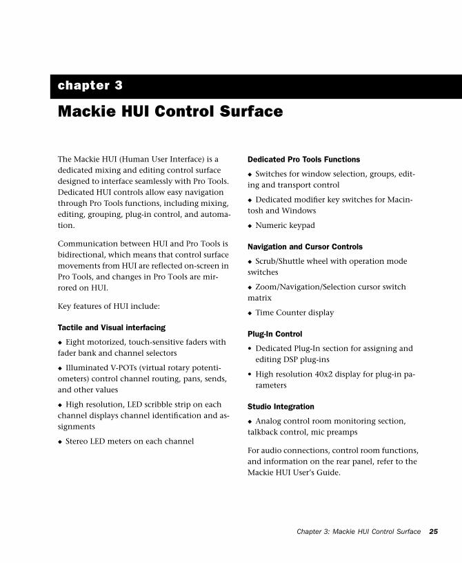
The Mackie HUI (Human User Interface) is a dedicated mixing and editing control surface designed to interface seamlessly with Pro Tools. Dedicated HUI controls allow easy navigation through Pro Tools functions, including mixing, editing, grouping, plug-in control, and automa-tion.
Communication between HUI and Pro Tools is bidirectional, which means that control surface movements from HUI are reflected on-screen in Pro Tools, and changes in Pro Tools are mir-rored on HUI.
Key features of HUI include:
Tactile and Visual interfacing
◆ Eight motorized, touch-sensitive faders with fader bank and channel selectors
◆ Illuminated V-POTs (virtual rotary potenti-ometers) control channel routing, pans, sends, and other values
◆ High resolution, LED scribble strip on each channel displays channel identification and as-signments
◆ Stereo LED meters on each channel
Dedicated Pro Tools Functions
◆ Switches for window selection, groups, edit-ing and transport control
◆ Dedicated modifier key switches for Macin-tosh and Windows
◆ Numeric keypad
Navigation and Cursor Controls
◆ Scrub/Shuttle wheel with operation mode switches
◆ Zoom/Navigation/Selection cursor switch matrix
◆ Time Counter display
Plug-In Control
• Dedicated Plug-In section for assigning and editing DSP plug-ins
• High resolution 40x2 display for plug-in pa-rameters
Studio Integration
◆ Analog control room monitoring section, talkback control, mic preamps
For audio connections, control room functions, and information on the rear panel, refer to the Mackie HUI User’s Guide.
MIDI Control Surfaces Guide26
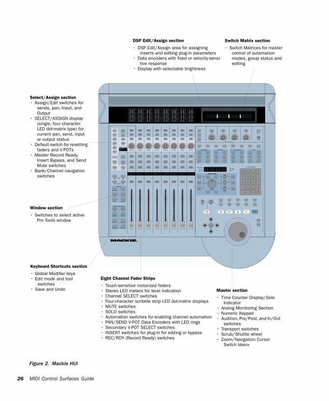
Figure 2. Mackie HUI
REC/RDY
INSERT
REC/RDY
INSERT
REC/RDY
INSERT
REC/RDY
INSERT
REC/RDY
INSERT
REC/RDY
INSERT
REC/RDY
INSERT
REC/RDY
INSERT
V-SEL V-SEL V-SEL V-SEL V-SEL V-SEL V-SEL V-SEL
MUTE
SOLO
AUTO
MUTE MUTE
SOLOSOLO
AUTO AUTOAUTO
MUTE MUTE MUTE MUTE
SOLOSOLOSOLOSOLO
AUTO AUTO AUTO
MUTE
SOLO
AUTO
SELECT SELECT SELECT SELECT SELECT SELECT SELECT SELECT
FAST FWD STOP PLAY RECORD
ZOOM
-+
CLR *= /
7 8 9
4 5 6
1 2 3
0
ENTER.
REWINDTALKBACK
PAN/SEND
CHANNEL
BANK
SCRUB
SHUTTLE
MASTERVOLUME
MUTE
OUTPUT 1
DIM
1:1 DISCRETE MONOINPUT 1
INPUT 3
INPUT 2
OUTPUT 3
OUTPUT 2
SPKR 1
PHONES/SPKR 3
SPKR 2
PAN/SENDPAN/SENDPAN/SENDPAN/SENDPAN/SENDPAN/SENDPAN/SEND
SELECT SELECT SELECT
SCROLL
F6 F7F1 F2 F3 F4 F5 F8/ESC
AUTO
PLUG IN SEND MUTE TRIM OFF PHASE SUSPEND
PAN SEND LATCH WRITE MONITOR CREATE
PASTE
CUT
FADER MUTE READ TOUCH GROUP CAPTURE
DELETE
COPY
SEPARATE
ASSIGN
SELECT-ASSIGN
KEYBOARD SHORTCUTS
WINDOW
SHIFT/ADD
CTRL/CLUTCH
OPTION/ALL
EDIT MODE EDIT TOOL
UNDO SAVE
ALT/FINE
EDIT
MIX
STATUS
TRANSPORT ALT
MEM-LOC
TIME CODE
FEETRUDESOLOLIGHTBEATS
AUTO ENABLE AUTO MODE
LOCATE/NUMERICS
CONTROL ROOM
DSP EDIT/ASSIGN
EDITSTATUS/GROUP
SEND B
SEND C
SEND D
SEND E
PAN
SEND A REC/RDY ALL
BYPASS
MUTE
SHIFT
INSERTPARAM
ASSIGN
DEFAULT
OUTPUT
INPUT
SUSPEND
AUDITION
RTZ
PRE
END
IN
ON LINE
OUT
LOOP
POST
QUICK PUNCHMICLEVEL
MAX
CONTROL ROOM
SELECT SELECT
COMPARE
ASSIGN
BYPASS
OO
0246810142030405060
0246810142030405060
0246810142030405060
0246810142030405060
0246810142030405060
0246810142030405060
0246810142030405060
Keyboard Shortcuts section
• Global Modifier keys• Edit mode and tool
switches• Save and Undo
DSP Edit/Assign section
• DSP Edit/Assign area for assigning inserts and editing plug-in parameters
• Data encoders with fixed or velocity-sensi-tive response
• Display with selectable brightness
Switch Matrix section
• Switch Matrices for master control of automation modes, group status and editing
Eight Channel Fader Strips
• Touch-sensitive motorized faders• Stereo LED meters for level indication• Channel SELECT switches• Four-character scribble strip LED dot-matrix displays• MUTE switches• SOLO switches• Automation switches for enabling channel automation• PAN/SEND V-POT Data Encoders with LED rings• Secondary V-POT SELECT switches• INSERT switches for plug-in for editing or bypass• REC/RDY (Record Ready) switches
Select/Assign section • Assign/Edit switches for
sends, pan, Input, and Output
• SELECT/ASSIGN display (single, four character LED dot-matrix type) for current pan, send, input or output status
• Default switch for resetting faders and V-POTs
• Master Record Ready, Insert Bypass, and Send Mute switches
• Bank/Channel navigation switches
Window section
• Switches to select active Pro Tools window
Master section
• Time Counter Display/Solo Indicator
• Analog Monitoring Section• Numeric Keypad• Audition, Pre/Post, and In/Out
switches• Transport switches• Scrub/Shuttle wheel• Zoom/Navigation Cursor
Switch Matrix
Chapter 3: Mackie HUI Control Surface 27
Communication with HUI
Here are some general guidelines for communi-cation between HUI and Pro Tools:
Pro Tools On-Screen Dialog Warnings
Certain dialog messages that appear on-screen in Pro Tools will also appear in the HUI display. You must close these dialogs before continuing work with the HUI.
Pro Tools “Lost Communication” Message
If Pro Tools loses communication with the HUI, it will display “OFFLINE” in its Time Counter Display. If this occurs, turn off power to the HUI, wait a few seconds, and then turn on the HUI again. If communication problems persist, check connections to the HUI.
When Pro Tools has reestablished communica-tions with the HUI, the far-right decimal point LED in the Time Code Display will flash, indi-cating that communication has been estab-lished and is valid.
If you are not using the HUI, deselect it in the MIDI control surfaces field in the Peripherals di-alog.
Active in Background Message
In most setups, the Pro Tools Active in Back-ground option should be selected in the Opera-tions menu.
If this option is not selected and another appli-cation is brought to the foreground, a warning will appear in the HUI display. Select Operations > Active in Background, and HUI activity will be restored.
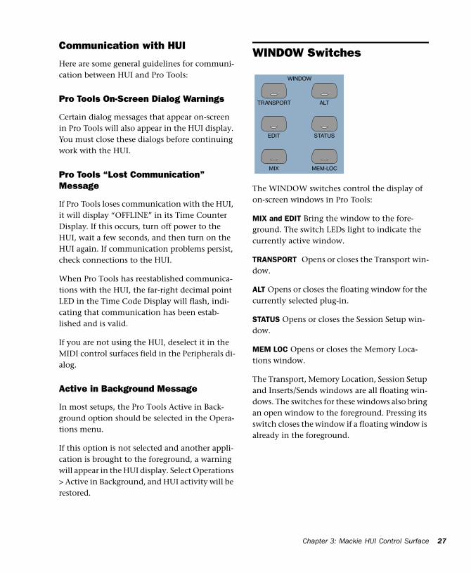
WINDOW Switches
The WINDOW switches control the display of on-screen windows in Pro Tools:
MIX and EDIT Bring the window to the fore-ground. The switch LEDs light to indicate the currently active window.
TRANSPORT Opens or closes the Transport win-dow.
ALT Opens or closes the floating window for the currently selected plug-in.
STATUS Opens or closes the Session Setup win-dow.
MEM LOC Opens or closes the Memory Loca-tions window.
The Transport, Memory Location, Session Setup and Inserts/Sends windows are all floating win-dows. The switches for these windows also bring an open window to the foreground. Pressing its switch closes the window if a floating window is already in the foreground.
EDIT
MIX
STATUS
TRANSPORT ALT
MEM-LOC
WINDOW
MIDI Control Surfaces Guide28
Plug-In Window
The ALT switch opens or closes the Plug-In win-dow for the currently selected plug-in, as indi-cated in the DSP/EDIT display by the flashing insert on the INSERTS view, or by the currently active plug-in on the PARAM view. When a plug-in is selected for editing on HUI, the corre-sponding Plug-In window opens in Pro Tools. Only a single plug-in can be opened and edited at a time.
Scrolling the Edit and Mix Windows
To scroll the Edit window:
■ While the Edit window is in the foreground, press ALT/FINE+Left or Right Arrow to scroll one page in either direction.
To scroll the Mix window:
■ While the Mix window is in the foreground, press ALT/FINE+Left or Right Arrow to scroll one page in either direction.
To scroll to session start or end:
■ Press ALT/FINE+OPTION/ALL+Left Arrow to scroll to session start.
■ Press ALT/FINE+OPTION/ALL+Right Arrow to scroll to session end.
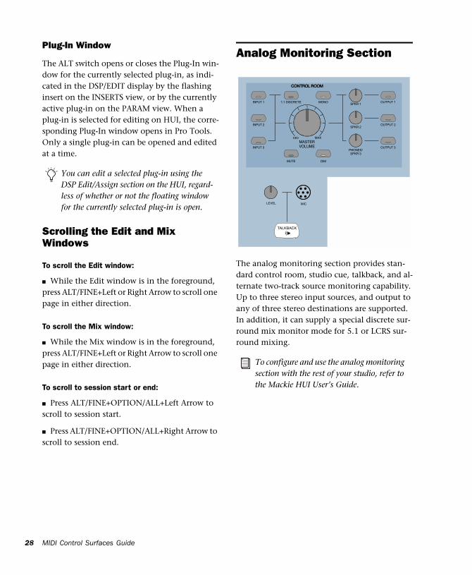
Analog Monitoring Section
The analog monitoring section provides stan-dard control room, studio cue, talkback, and al-ternate two-track source monitoring capability. Up to three stereo input sources, and output to any of three stereo destinations are supported. In addition, it can supply a special discrete sur-round mix monitor mode for 5.1 or LCRS sur-round mixing.
You can edit a selected plug-in using the DSP Edit/Assign section on the HUI, regard-less of whether or not the floating window for the currently selected plug-in is open.
To configure and use the analog monitoring section with the rest of your studio, refer to the Mackie HUI User’s Guide.
TALKBACK
MASTERVOLUME
MUTE
OUTPUT 1
DIM
1:1 DISCRETE MONOINPUT 1
INPUT 3
INPUT 2
OUTPUT 3
OUTPUT 2
SPKR 1
PHONES/SPKR 3
SPKR 2
CONTROL ROOM
MAX
CONTROL ROOM
OO
MICLEVEL
Chapter 3: Mackie HUI Control Surface 29
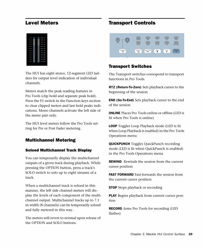
Level Meters
The HUI has eight stereo, 12-segment LED lad-ders for output level indication of individual channels.
Meters match the peak reading features in Pro Tools (clip hold and separate peak hold). Press the F1 switch in the Function keys section to clear clipped meters and last held peaks indi-cations. Mono channels activate the left side of the meter pair only.
The HUI level meters follow the Pro Tools set-ting for Pre or Post Fader metering.
Multichannel Metering
Soloed Multichannel Track Display
You can temporarily display the multichannel outputs of a given track during playback. While pressing the OPTION button, press a track’s SOLO switch to solo up to eight streams of a track.
When a multichannel track is soloed in this manner, the left side channel meters will dis-play the levels of each component of the multi-channel output. Multichannel tracks up to 7.1 in width (8 channels) can be temporarily soloed and fully metered in this way.
The meters will revert to normal upon release of the OPTION and SOLO buttons.
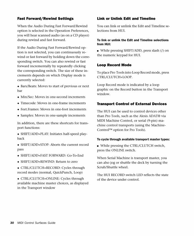
Transport Controls
Transport Switches
The Transport switches correspond to transport functions in Pro Tools.
RTZ (Return-To-Zero) Sets playback cursor to the beginning of the session
END (Go-To-End) Sets playback cursor to the end of the session
ONLINE Places Pro Tools online or offline (LED is lit when Pro Tools is online)
LOOP Toggles Loop Playback mode (LED is lit when Loop Playback is enabled) in the Pro Tools Operations menu
QUICKPUNCH Toggles QuickPunch recording mode (LED is lit when QuickPunch is enabled) in the Pro Tools Operations menu
REWIND Rewinds the session from the current cursor position
FAST FORWARD Fast-forwards the session from the current cursor position
STOP Stops playback or recording
PLAY Begins playback from current cursor posi-tion
RECORD Arms Pro Tools for recording (LED flashes)
0246810142030405060
FAST FWD STOP PLAY RECORDREWINDTALKBACK
AUDITION
RTZ
PRE
END
IN
ON LINE
OUT
LOOP
POST
QUICK PUNCHMICLEVEL
MIDI Control Surfaces Guide30
Fast Forward/Rewind Settings
When the Audio During Fast Forward/Rewind option is selected in the Operation Preferences, you will hear scanned audio (as on a CD player) during rewind and fast forward.
If the Audio During Fast Forward/Rewind op-tion is not selected, you can continuously re-wind or fast forward by holding down the corre-sponding switch. You can also rewind or fast forward incrementally by repeatedly clicking the corresponding switch. The size of these in-crements depends on which Display mode is currently selected:
◆ Bars/Beats: Moves to start of previous or next bar
◆ Min/Sec: Moves in one-second increments
◆ Timecode: Moves in one-frame increments
◆ Feet.Frames: Moves in one-foot increments
◆ Samples: Moves in one-sample increments
In addition, there are these shortcuts for trans-port functions:
◆ SHIFT/ADD+PLAY: Initiates half-speed play-back
◆ SHIFT/ADD+STOP: Aborts the current record pass
◆ SHIFT/ADD+FAST FORWARD: Go-To-End
◆ SHIFT/ADD+REWIND: Return to zero
◆ CTRL/CLUTCH+RECORD: Cycles through record modes (normal, QuickPunch, Loop)
◆ CTRL/CLUTCH+ONLINE: Cycles through available machine master choices, as displayed in the Transport window
Link or Unlink Edit and Timeline
You can link or unlink the Edit and Timeline se-lections from HUI.
To link or unlink the Edit and Timeline selections from HUI:
■ While pressing SHIFT/ADD, press slash (/) on the numeric keypad for HUI.
Loop Record Mode
To place Pro Tools into Loop Record mode, press CTRL/CLUTCH+LOOP.
Loop Record mode is indicated by a loop graphic on the Record button in the Transport window.
Transport Control of External Devices
The HUI can be used to control devices other than Pro Tools, such as the Alesis ADAT® via MIDI Machine Control, or serial (9-pin) ma-chine control transports (using the Machine-Control™ option for Pro Tools).
To cycle through available transport master types:
■ While pressing the CTRL/CLUTCH switch, press the ONLINE switch.
When Serial Machine is transport master, you can also jog or shuttle the deck by turning the Scrub/Shuttle wheel.
The HUI RECORD switch LED reflects the state of the device under control.

Chapter 3: Mackie HUI Control Surface 31
Footswitch Control
There are two footswitch inputs on the HUI rear panel for transport control.
Footswitch #1 performs the following functions:
◆ If Pro Tools is playing back, press Footswitch #1 to stop.
◆ If Pro Tools is recording, press SHIFT/ADD and Footswitch #1 to abort the recording.
◆ If Pro Tools is stopped, press Footswitch #1 to start playback.
◆ Press SHIFT/ADD and Footswitch #1 to start half-speed playback.
Footswitch #2 performs the following functions:
◆ Press Footswitch #2 to toggle the Pro Tools record state on or off.
◆ Press CTRL/CLUTCH and Footswitch #2 to cy-cle through available record modes (destructive or nondestructive).
AUDITION, PRE/POST, and IN/OUT Switches
The AUDITION switch is used with the PRE/POST and IN/OUT switches to play cur-rently selected audio. Playback continues until AUDITION is pressed again or until another transport button is pressed.
The PRE and POST switches activate pre-roll and post-roll. These switches also work with the AU-DITION switch to audition around various edit areas.
The IN and OUT switches can be used to mark In and Out edit points during playback. These switches also work with the AUDITION switch to audition In/Out edit points.
Setting Pre and Post Roll
To enter a pre-roll or post-roll time:
1 Press ALT/FINE+PRE or POST.
2 Enter values on the numeric keypad. This en-ters a pre-roll or post-roll time according to the Grid/Time Display value.
3 Press the Left and Right Arrows to cycle through the numeric fields in the Pre-Roll or Post-Roll counters in the Pro Tools Transport window. Press the Up and Down Arrows to in-crease or decrease the current numeric field value. Press CLR to clear the counters.
4 To confirm the entered time value, press EN-TER. To enter the same value for both pre-roll and post-roll, press OPTION/ALL+ ENTER.
– or –
Press F8/ESC to abort numeric entry and leave the times unchanged.
AUDITION
RTZ
PRE
END
IN
ON LINE
OUT
LOOP
POST
QUICK PUNCH
You can leave an audition mode at any time, and go to any other audition mode or transport command.
MIDI Control Surfaces Guide32
To manually enter selection start and end times:
1 Press ALT/FINE+IN or OUT in the Audition switch matrix.
2 Enter values on the numeric keypad. This en-ters a Start or End time according to the Grid/Time Display value used in Pro Tools.
3 Press the Left or Right Arrows to cycle through the numeric fields in the Start and End counters in the Pro Tools Transport window. Press the Up or Down Arrows to increase or decrease the cur-rent numeric field value. Press CLR to clear the counters.
4 To confirm the entered time value, press the ENTER switch. (To enter the same value for both Start and End times, press the OPTION/ALL+EN-TER).
– or –
Press the F8/ESC switch to abort numeric entry and leave the times unchanged.
AUDITION Functions
To audition an edit point, press AUDITION and PRE, IN, OUT or POST.
Playback continues until AUDITION is pressed again or until another transport button is pressed.
PRE Plays audio starting at the pre-roll point up to the beginning of the selection.
IN Plays audio starting at the beginning of the selection and lasting the length of the post-roll amount.
OUT Plays audio starting before the selection end point by the pre-roll amount.
POST Plays audio starting at the end of a selec-tion and lasting the length of the post-roll amount.
In addition, there are these shortcuts for audi-tion functions:
◆ Press ALT/FINE+OPTION/ALL, and PRE or IN to play audio starting at the pre-roll point, con-tinuing through the selection start, and ending after the selection start point by the post-roll amount.
◆ Press ALT/FINE+OPTION/ALL. and OUT or POST to play audio starting before the selection end point by the pre-roll amount, continuing through the selection end point, and ending af-ter the selection end point by the post-roll amount.
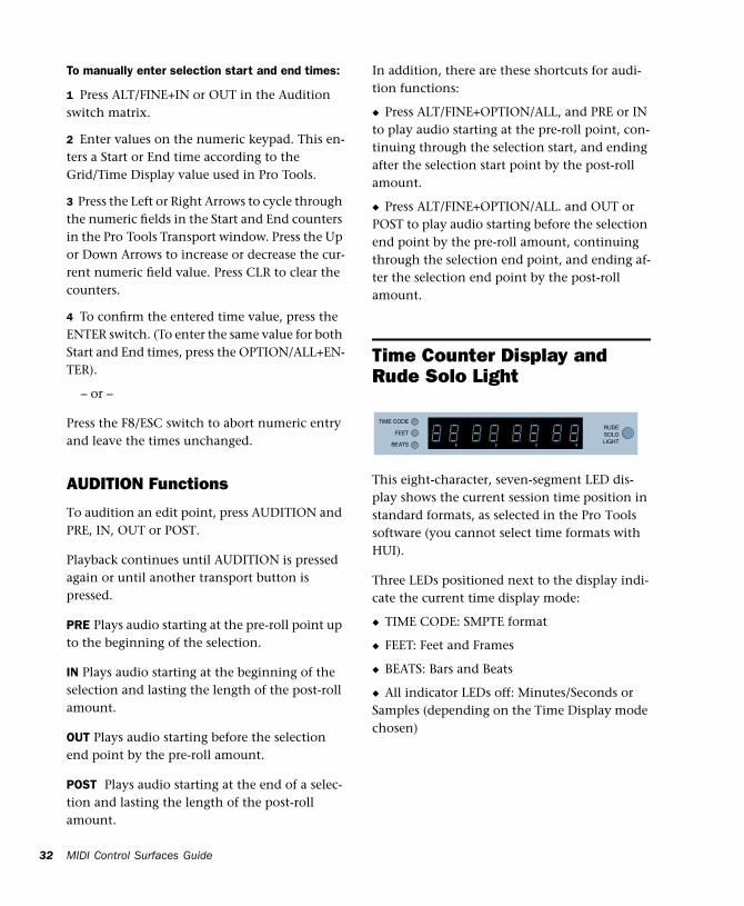
Time Counter Display and Rude Solo Light
This eight-character, seven-segment LED dis-play shows the current session time position in standard formats, as selected in the Pro Tools software (you cannot select time formats with HUI).
Three LEDs positioned next to the display indi-cate the current time display mode:
◆ TIME CODE: SMPTE format
◆ FEET: Feet and Frames
◆ BEATS: Bars and Beats
◆ All indicator LEDs off: Minutes/Seconds or Samples (depending on the Time Display mode chosen)
TIME CODE
FEETRUDESOLOLIGHTBEATS
Chapter 3: Mackie HUI Control Surface 33
Host Communication Status LED
When Pro Tools is communicating properly with the HUI, the far-right decimal point LED in the Time Code Display will flash.
Rude Solo Light
The Rude Solo Light flashes whenever there is at least one channel in the current session that is soloed.
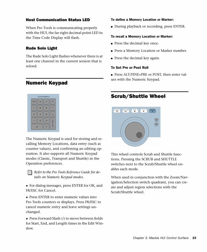
Numeric Keypad
The Numeric Keypad is used for storing and re-calling Memory Locations, data entry (such as counter values), and confirming an editing op-eration. It also supports all Numeric Keypad modes (Classic, Transport and Shuttle) in the Operation preferences.
◆ For dialog messages, press ENTER for OK, and F8/ESC for Cancel.
◆ Press ENTER to enter numeric values into Pro Tools counters or displays. Press F8/ESC to cancel numeric entry and leave settings un-changed.
◆ Press Forward Slash (/) to move between fields for Start, End, and Length times in the Edit Win-dow.
To define a Memory Location or Marker:
■ During playback or recording, press ENTER.
To recall a Memory Location or Marker:
■ Press the decimal key once.
■ Press a Memory Location or Marker number.
■ Press the decimal key again.
To Set Pre or Post Roll
■ Press ALT/FINE+PRE or POST, then enter val-ues with the Numeric Keypad.
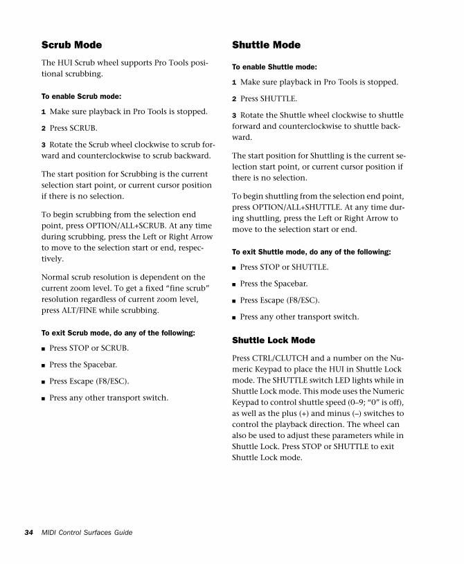
Scrub/Shuttle Wheel
This wheel controls Scrub and Shuttle func-tions. Pressing the SCRUB and SHUTTLE switches next to the Scrub/Shuttle wheel en-ables each mode.
When used in conjunction with the Zoom/Nav-igation/Selection switch quadrant, you can cre-ate and adjust region selections with the Scrub/Shuttle wheel.
Refer to the Pro Tools Reference Guide for de-tails on Numeric Keypad modes.
-+
CLR *= /
7 8 9
4 5 6
1 2 3
0
ENTER.
LOCATE/NUMERICS
FAST FWD STOP PLAY RECORDREWIND
SCRUB
SHUTTLE
MIDI Control Surfaces Guide34
Scrub Mode
The HUI Scrub wheel supports Pro Tools posi-tional scrubbing.
To enable Scrub mode:
1 Make sure playback in Pro Tools is stopped.
2 Press SCRUB.
3 Rotate the Scrub wheel clockwise to scrub for-ward and counterclockwise to scrub backward.
The start position for Scrubbing is the current selection start point, or current cursor position if there is no selection.
To begin scrubbing from the selection end point, press OPTION/ALL+SCRUB. At any time during scrubbing, press the Left or Right Arrow to move to the selection start or end, respec-tively.
Normal scrub resolution is dependent on the current zoom level. To get a fixed “fine scrub” resolution regardless of current zoom level, press ALT/FINE while scrubbing.
To exit Scrub mode, do any of the following:
■ Press STOP or SCRUB.
■ Press the Spacebar.
■ Press Escape (F8/ESC).
■ Press any other transport switch.
Shuttle Mode
To enable Shuttle mode:
1 Make sure playback in Pro Tools is stopped.
2 Press SHUTTLE.
3 Rotate the Shuttle wheel clockwise to shuttle forward and counterclockwise to shuttle back-ward.
The start position for Shuttling is the current se-lection start point, or current cursor position if there is no selection.
To begin shuttling from the selection end point, press OPTION/ALL+SHUTTLE. At any time dur-ing shuttling, press the Left or Right Arrow to move to the selection start or end.
To exit Shuttle mode, do any of the following:
■ Press STOP or SHUTTLE.
■ Press the Spacebar.
■ Press Escape (F8/ESC).
■ Press any other transport switch.
Shuttle Lock Mode
Press CTRL/CLUTCH and a number on the Nu-meric Keypad to place the HUI in Shuttle Lock mode. The SHUTTLE switch LED lights while in Shuttle Lock mode. This mode uses the Numeric Keypad to control shuttle speed (0–9; “0” is off), as well as the plus (+) and minus (–) switches to control the playback direction. The wheel can also be used to adjust these parameters while in Shuttle Lock. Press STOP or SHUTTLE to exit Shuttle Lock mode.
Chapter 3: Mackie HUI Control Surface 35
Scrub/Shuttle “Lock Out” Behavior
When scrub or shuttle is engaged, only certain controls are available:
◆ Channel faders, Mute and Solo switches
◆ Scrub/Shuttle wheel and switches
◆ Any transport switch (disengages Scrub and Shuttle modes)
◆ ENTER (creates a Memory Location)
Scrub/Shuttle Operation using Serial Machine Control
You can also use the Scrub/Shuttle wheel to scrub (jog) or shuttle an external, serial machine control-capable deck if you are using the Digide-sign MachineControl software option.
When Serial Machine is transport master, you can do the following:
■ Press SCRUB and turn the wheel to jog the ex-ternal machine.
■ Press SHUTTLE and turn the wheel to shuttle the external machine.
■ To leave either mode, press SCRUB or SHUT-TLE again, or press any other transport switch.
Creating Selections Using the Scrub/Shuttle Wheel
You can create and modify on-screen selections using the Scrub/Shuttle wheel.
To create selections using the Scrub/Shuttle wheel:
■ While pressing SHIFT/ADD, press SCRUB or SHUTTLE. The start position is the current selec-tion’s start point, or current location of the cur-sor if there is no selection.
To SCRUB or SHUTTLE from the selection end point, press OPTION/ALL+SCRUB or SHUTTLE.
To modify the end of an existing selection:
■ While pressing SHIFT/ADD and OPTION/ALL, press SCRUB or SHUTTLE and use the Scrub/Shuttle wheel to make your modifica-tions.
To modify the beginning of an existing selection:
■ While pressing SHIFT/ADD, press SCRUB or SHUTTLE and use the Scrub/Shuttle wheel to make your modifications.
You can navigate to the start or end of your se-lection at any time by pressing the Left or Right Arrow keys.
Insertion Follows Scrub/Shuttle Preference
How you work with the Scrub/Shuttle wheel de-pends on whether you select the “Edit Insertion Follows Scrub/Shuttle” Operation preference in Pro Tools.
If “Insertion Follows Scrub/Shuttle” is selected:
■ Press SCRUB or SHUTTLE and move the wheel to clear the current selection and move the cur-sor.
■ Press SHIFT/ADD before pressing SCRUB or SHUTTLE, or before moving the wheel, to keep the current selection. As you move the wheel, the selection is expanded or trimmed.
■ While pressing SHIFT/ADD and OPTION/ALL, press SCRUB or SHUTTLE and use the Scrub/Shuttle wheel to further modify the end of your selection.
MIDI Control Surfaces Guide36
If “Insertion Follows Scrub/Shuttle” is not selected:
■ Press SCRUB or SHUTTLE and turn the wheel to keep your current selection and move the cur-sor outside of the selection.
■ Press SHIFT/ADD and turn the wheel to clear the current selection and create a new one. The new selection starts wherever you first press SHIFT/ADD.
■ Release SHIFT/ADD to move the cursor out-side the new selection.
■ Press SHIFT/ADD additional times to trim the new selection as needed.
Scrub/Shuttle Tips
◆ At any time during scrubbing or shuttling, you can press the Left or Right Arrow to move the current scrub position to the selection start or end.
◆ You can freely move between scrub and shut-tle modes. The current SCRUB or SHUTTLE po-sition is retained.
◆ If you enter scrub or shuttle but don’t move the wheel or mouse, you can exit Scrub or Shut-tle mode without affecting the current selection.
To define a selection using a combination of SCRUB or SHUTTLE functions:
1 Press SHUTTLE to enter Shuttle mode.
2 Shuttle along the timeline. When you get to roughly the selection in-point, press SHIFT/ADD.
3 Continue shuttling down the timeline. When you get to roughly the out-point, release SHIFT/ADD. Your “rough selection” is now de-fined.
4 Press SCRUB to enter Scrub mode.
5 Press the Left Arrow key to move the scrub po-sition to the selection start.
6 Press SHIFT/ADD (to retain the selection), and scrub the selection in-point until you reach the desired location.
7 Press the Right Arrow key to move the scrub out-point to the selection end.
8 Press SHIFT/ADD (to retain the selection), and scrub the selection out-point until you reach the desired location.
Capturing Memory Locations
When working with Scrub and Shuttle func-tions, you can do the following:
◆ Memory Locations can be captured at any time by pressing the ENTER key on the HUI nu-meric keypad.
◆ Press the Up Arrow to free the cursor without capturing a Memory Location.
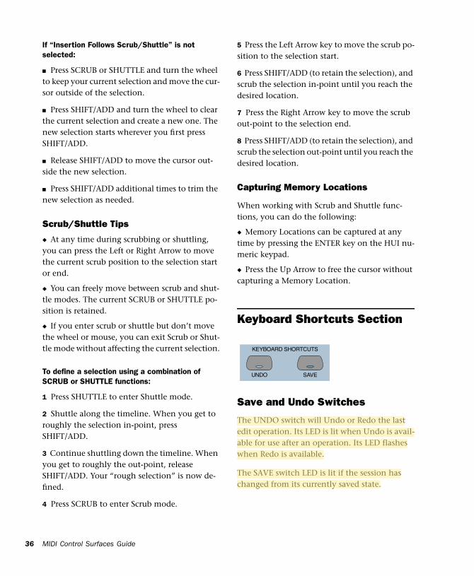
Keyboard Shortcuts Section
Save and Undo Switches
The UNDO switch will Undo or Redo the last edit operation. Its LED is lit when Undo is avail-able for use after an operation. Its LED flashes when Redo is available.
The SAVE switch LED is lit if the session has changed from its currently saved state.
UNDO SAVE
KEYBOARD SHORTCUTS
Chapter 3: Mackie HUI Control Surface 37
To save the changes in a session:
1 Press SAVE. The SAVE switch LED flashes when first pressed, indicating the Save process has been armed.
2 Do one of the following:
■ To complete the Save process, press the SAVE switch again.
■ To abort the Save process, press the F8/ESC switch.
EDIT MODE and EDIT TOOL Switches
The EDIT MODE and EDIT TOOL switches ac-cess the primary Edit function modes and tools:
EDIT MODE Cycles through the four edit modes: Shuffle, Slip, Spot, and Grid.
EDIT TOOL Cycles through the main edit tools: Zoom, Trim, Select, Grabber, Smart Tool, Scrub, and Pencil.
Smart Tool Press EDIT TOOL+7 (on the numeric keypad) to select the Smart Tool.
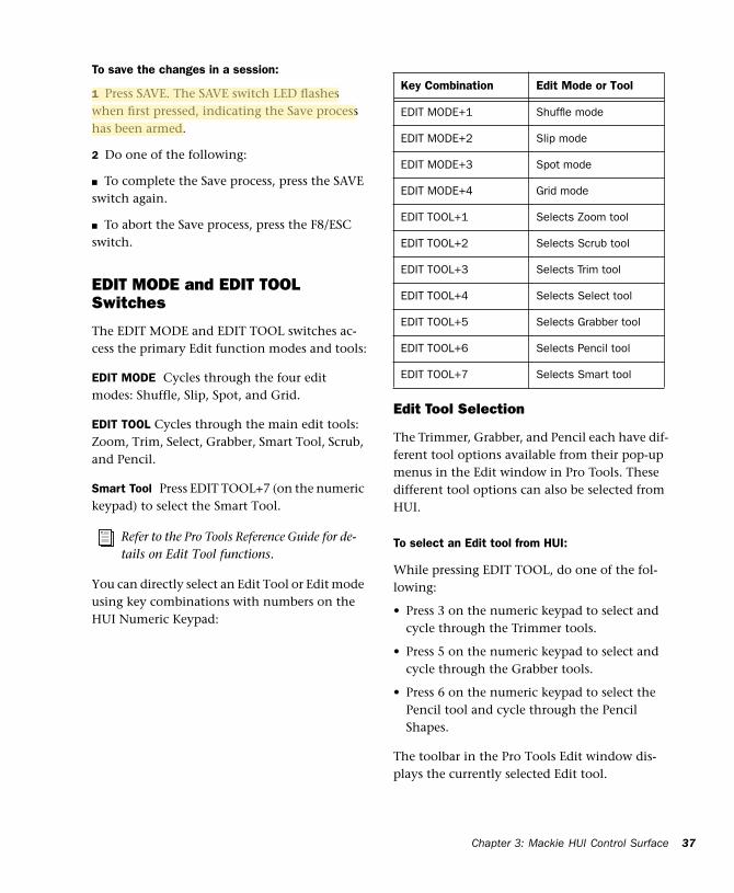
You can directly select an Edit Tool or Edit mode using key combinations with numbers on the HUI Numeric Keypad:
Edit Tool Selection
The Trimmer, Grabber, and Pencil each have dif-ferent tool options available from their pop-up menus in the Edit window in Pro Tools. These different tool options can also be selected from HUI.
To select an Edit tool from HUI:
While pressing EDIT TOOL, do one of the fol-lowing:
• Press 3 on the numeric keypad to select and cycle through the Trimmer tools.
• Press 5 on the numeric keypad to select and cycle through the Grabber tools.
• Press 6 on the numeric keypad to select the Pencil tool and cycle through the Pencil Shapes.
The toolbar in the Pro Tools Edit window dis-plays the currently selected Edit tool.
Refer to the Pro Tools Reference Guide for de-tails on Edit Tool functions.
Key Combination Edit Mode or Tool
EDIT MODE+1 Shuffle mode
EDIT MODE+2 Slip mode
EDIT MODE+3 Spot mode
EDIT MODE+4 Grid mode
EDIT TOOL+1 Selects Zoom tool
EDIT TOOL+2 Selects Scrub tool
EDIT TOOL+3 Selects Trim tool
EDIT TOOL+4 Selects Select tool
EDIT TOOL+5 Selects Grabber tool
EDIT TOOL+6 Selects Pencil tool
EDIT TOOL+7 Selects Smart tool
MIDI Control Surfaces Guide38
Extending Region Selections
Pro Tools provides several key commands for changing or extending region selections in the Edit window. When the HUI arrow keys are in region navigation mode:
◆ CONTROL+Left Arrow: Selects the previous region.
◆ CONTROL+Right Arrow: Selects the next re-gion.
◆ CONTROL+SHIFT+Left Arrow: Extends the se-lection to include the previous region.
◆ CONTROL+SHIFT+Right Arrow: Extends the selection to include the next region.
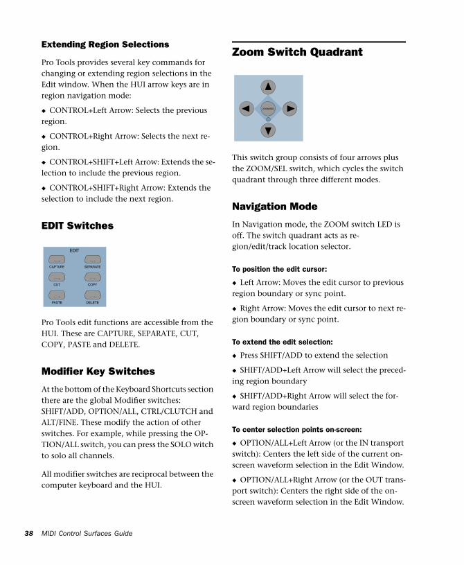
EDIT Switches
Pro Tools edit functions are accessible from the HUI. These are CAPTURE, SEPARATE, CUT, COPY, PASTE and DELETE.
Modifier Key Switches
At the bottom of the Keyboard Shortcuts section there are the global Modifier switches: SHIFT/ADD, OPTION/ALL, CTRL/CLUTCH and ALT/FINE. These modify the action of other switches. For example, while pressing the OP-TION/ALL switch, you can press the SOLO witch to solo all channels.
All modifier switches are reciprocal between the computer keyboard and the HUI.
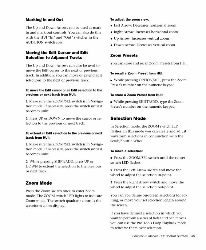
Zoom Switch Quadrant
This switch group consists of four arrows plus the ZOOM/SEL switch, which cycles the switch quadrant through three different modes.
Navigation Mode
In Navigation mode, the ZOOM switch LED is off. The switch quadrant acts as re-gion/edit/track location selector.
To position the edit cursor:
◆ Left Arrow: Moves the edit cursor to previous region boundary or sync point.
◆ Right Arrow: Moves the edit cursor to next re-gion boundary or sync point.
To extend the edit selection:
◆ Press SHIFT/ADD to extend the selection
◆ SHIFT/ADD+Left Arrow will select the preced-ing region boundary
◆ SHIFT/ADD+Right Arrow will select the for-ward region boundaries
To center selection points on-screen:
◆ OPTION/ALL+Left Arrow (or the IN transport switch): Centers the left side of the current on-screen waveform selection in the Edit Window.
◆ OPTION/ALL+Right Arrow (or the OUT trans-port switch): Centers the right side of the on-screen waveform selection in the Edit Window.
PASTE
CUT
CAPTURE
DELETE
COPY
SEPARATE
EDIT
ZOOM/SEL
Chapter 3: Mackie HUI Control Surface 39
Marking In and Out
The Up and Down Arrows can be used as mark-in and mark-out controls. You can also do this with the HUI “In” and “Out” switches in the AUDITION switch row.
Moving the Edit Cursor and Edit Selection to Adjacent Tracks
The Up and Down Arrows can also be used to move the Edit cursor to the next or previous track. In addition, you can move or extend Edit selections to the next or previous track.
To move the Edit cursor or an Edit selection to the previous or next track from HUI:
1 Make sure the ZOOM/SEL switch is in Naviga-tion mode. If necessary, press the switch until it becomes unlit.
2 Press UP or DOWN to move the cursor or se-lection to the previous or next track.
To extend an Edit selection to the previous or next track from HUI:
1 Make sure the ZOOM/SEL switch is in Naviga-tion mode. If necessary, press the switch until it becomes unlit.
2 While pressing SHIFT/ADD, press UP or DOWN to extend the selection to the previous or next track.
Zoom Mode
Press the Zoom switch once to enter Zoom mode. The ZOOM switch LED lights to indicate Zoom mode. The switch quadrant controls the waveform zoom display.
To adjust the zoom view:
◆ Left Arrow: Decreases horizontal zoom
◆ Right Arrow: Increases horizontal zoom
◆ Up Arrow: Increases vertical zoom
◆ Down Arrow: Decreases vertical zoom
Zoom Presets
You can store and recall Zoom Presets from HUI.
To recall a Zoom Preset from HUI:
■ While pressing OPTION/ALL, press the Zoom Preset’s number on the numeric keypad.
To store a Zoom Preset from HUI:
■ While pressing SHIFT/ADD, type the Zoom Preset’s number on the numeric keypad.
Selection Mode
In Selection mode, the ZOOM switch LED flashes. In this mode you can create and adjust waveform selections in conjunction with the Scrub/Shuttle Wheel.
To make a selection:
1 Press the ZOOM/SEL switch until the center switch LED flashes.
2 Press the Left Arrow switch and move the wheel to adjust the selection in-point.
3 Press the Right Arrow switch and move the wheel to adjust the selection out-point.
You can you define on-screen selections for ed-iting, or move your set selection length around the screen.
If you have defined a selection in which you want to perform a series of fader and pan moves, you can use the Pro Tools Loop Playback mode to rehearse them over selection.
MIDI Control Surfaces Guide40
Selection Tips
These tips can also be helpful in making your se-lection:
◆ Press ALT/FINE to scrub at a fixed fine resolu-tion, regardless of the current zoom settings.
◆ Press SHIFT/ADD to make a new selection while scrubbing or shuttling. Release SHIFT/ADD to complete the selection.
◆ Press OPTION/ALL to begin scrubbing or shuttling from the end of a selection.
Once you have finished making a selection, you can adjust it using the following keyboard short-cuts while still in Scrub or Shuttle mode:
To position the edit cursor at a selection’s edge:
◆ Double-click the Left Arrow to position the cursor at the current selection’s left edge.
◆ Double-click the Right Arrow to position the cursor at the current selection’s right edge.
To move the edit selection:
◆ Up Arrow: Moves the selection to the previous track.
◆ Down Arrow: Moves the selection to the next track.
To adjust selection points:
◆ Left Arrow+Scrub/Shuttle wheel adjusts the selection IN point.
◆ Right Arrow+Scrub/Shuttle wheel adjusts the selection OUT point.
◆ Left Arrow+Right Arrow+Scrub/Shuttle wheel adjusts the selection’s time position while re-taining its duration.
To extend the edit selection:
◆ SHIFT/ADD+Up Arrow extends the selection to the previous track.
◆ SHIFT/ADD+Down Arrow extends the selec-tion to the next track.
◆ OPTION/ALL+Up Arrow removes the selec-tion from the topmost track.
◆ OPTION/ALL+Down Arrow removes the se-lection from the bottommost track.
Navigating On-Screen View of Pro Tools
You can also use the switch quadrant to navi-gate the Pro Tools on-screen view. The follow-ing switch functions apply to all three switch modes (Navigation mode, Zoom mode, and Se-lection mode):
To scroll the session view one window at a time:
◆ ALT/FINE+Left Arrow: Scrolls the frontmost window to the left.
◆ ALT/FINE+Right Arrow: Scrolls the frontmost window to the right.
◆ ALT/FINE+Up Arrow: Scrolls the frontmost window upward.
◆ ALT/FINE+Down Arrow: Scrolls the frontmost window downward.
Chapter 3: Mackie HUI Control Surface 41
To scroll to the beginning, end, top, or bottom of the session view:
◆ OPTION/ALL+ALT/FINE+Left Arrow: when the Edit window is in the foreground, scrolls to the beginning of the session.
◆ OPTION/ALL+ALT/FINE+Right Arrow: when the Edit window is in the foreground, scrolls to the end of the session.
◆ OPTION/ALL+ALT/FINE+Up Arrow: when the Edit window is in the foreground, scrolls to the top of the session.
◆ OPTION/ALL+ALT/FINE+Down Arrow: when the Edit window is in the foreground, scrolls to the bottom of session.
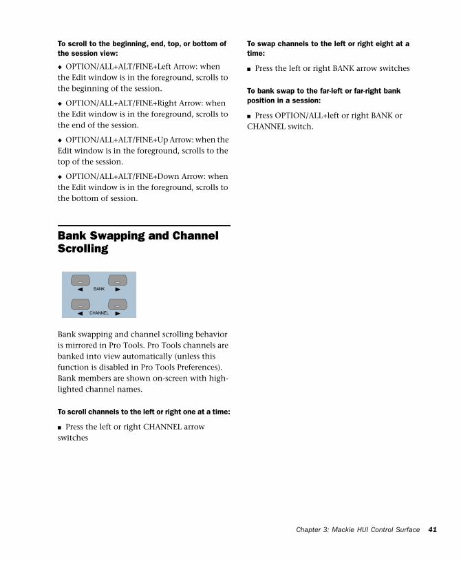
Bank Swapping and Channel Scrolling
Bank swapping and channel scrolling behavior is mirrored in Pro Tools. Pro Tools channels are banked into view automatically (unless this function is disabled in Pro Tools Preferences). Bank members are shown on-screen with high-lighted channel names.
To scroll channels to the left or right one at a time:
■ Press the left or right CHANNEL arrow switches
To swap channels to the left or right eight at a time:
■ Press the left or right BANK arrow switches
To bank swap to the far-left or far-right bank position in a session:
■ Press OPTION/ALL+left or right BANK or CHANNEL switch.
CHANNEL
BANK
MIDI Control Surfaces Guide42
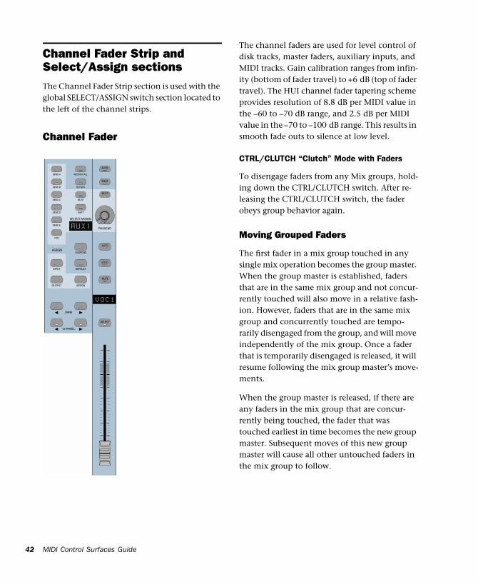
Channel Fader Strip and Select/Assign sectionsThe Channel Fader Strip section is used with the global SELECT/ASSIGN switch section located to the left of the channel strips.
Channel Fader
The channel faders are used for level control of disk tracks, master faders, auxiliary inputs, and MIDI tracks. Gain calibration ranges from infin-ity (bottom of fader travel) to +6 dB (top of fader travel). The HUI channel fader tapering scheme provides resolution of 8.8 dB per MIDI value in the –60 to –70 dB range, and 2.5 dB per MIDI value in the –70 to –100 dB range. This results in smooth fade outs to silence at low level.
CTRL/CLUTCH “Clutch” Mode with Faders
To disengage faders from any Mix groups, hold-ing down the CTRL/CLUTCH switch. After re-leasing the CTRL/CLUTCH switch, the fader obeys group behavior again.
Moving Grouped Faders
The first fader in a mix group touched in any single mix operation becomes the group master. When the group master is established, faders that are in the same mix group and not concur-rently touched will also move in a relative fash-ion. However, faders that are in the same mix group and concurrently touched are tempo-rarily disengaged from the group, and will move independently of the mix group. Once a fader that is temporarily disengaged is released, it will resume following the mix group master’s move-ments.
When the group master is released, if there are any faders in the mix group that are concur-rently being touched, the fader that was touched earliest in time becomes the new group master. Subsequent moves of this new group master will cause all other untouched faders in the mix group to follow.
CHANNEL
BANK
PAN/SEND
SEND B
SEND C
SEND D
SEND E
PAN
SEND A REC/RDY ALL
BYPASS
MUTE
SHIFT
ASSIGN
DEFAULT
OUTPUT
INPUT
SUSPEND
SOLO
AUTO
MUTE
SELECT
SOLO
AUTO
MUTE
SELECT-ASSIGN
ASSIGN
Chapter 3: Mackie HUI Control Surface 43
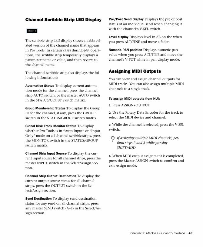
Channel Scribble Strip LED Display
The scribble-strip LED display shows an abbrevi-ated version of the channel name that appears in Pro Tools. In certain cases during edit opera-tions, the scribble strip temporarily displays a parameter name or value, and then reverts to the channel name.
The channel scribble strip also displays the fol-lowing information:
Automation Status To display current automa-tion mode for the channel, press the channel strip AUTO switch, or the master AUTO switch in the STATUS/GROUP switch matrix.
Group Membership Status To display the Group ID for the channel, if any, press the GROUP switch in the STATUS/GROUP switch matrix.
Global Disk Track Monitor Status To display whether Pro Tools is in “Auto Input” or “Input Only” mode on all channel scribble strips, press the MONITOR switch in the STATUS/GROUP switch matrix.
Channel Strip Input Source To display the cur-rent input source for all channel strips, press the master INPUT switch in the Select/Assign sec-tion.
Channel Strip Output Destination To display the current output source status for all channel strips, press the OUTPUT switch in the Se-lect/Assign section.
Send Destination To display send destination status for any send on all channel strips, press any master SEND switch (A–E) in the Select/As-sign section.
Pre/Post Send Display Displays the pre or post status of an individual send when changing it with the channel’s V-SEL switch.
Level display Displays level in dB on the when you press ALT/FINE and move a fader.
Numeric PAN position Displays numeric pan value when you press ALT/FINE and move the channel’s V-POT while in pan display mode.
Assigning MIDI Outputs
You can view and assign channel outputs for MIDI tracks. You can also assign multiple MIDI channels to a single track.
To assign MIDI outputs from HUI:
1 Press ASSIGN+OUTPUT.
2 Use the Rotary Data Encoder for the track to select the MIDI device and channel.
3 While the channel is selected, press the V-SEL switch.
4 When MIDI output assignment is completed, press the Master ASSIGN switch to confirm and exit Assign mode.
If assigning multiple MIDI channels, per-form steps 2 and 3 while pressing SHIFT/ADD.
MIDI Control Surfaces Guide44
Assigning Multiple Outputs
HUI supports the ability to assign multiple out-puts to a Pro Tools track.
To assign an additional output to a channel:
1 Press the master ASSIGN and OUTPUT switches (in the Select/Assign section).
2 On the appropriate channel, rotate the en-coder until it displays the additional output you want to assign. The currently assigned output (if any) is indicated with the > symbol (for exam-ple, “>Out 1–2”).
3 Press CTL|CLUTCH + ASSIGN to confirm the additional output assignment. Use the channel Assign/Mute or master Assign switch as needed:
■ The channel Assign/Mute switch confirms the setting and leaves HUI in Assign mode. Use this to continue assigning other channels.
■ Pressing the master ASSIGN switch confirms and exits Assign mode. Use this when you are through assigning channel outputs.
Display of Multiple Assignments
Multiple output assignments are indicated with “+” in front of the assigned path’s names. For ex-ample, +Out 1–2.
Other symbols indicate inactive status (see “In-active Outputs” on page 44).
Display of Inactive Items
The @ symbol indicates inactive status for the following items:
• Inputs
• Outputs
• Sends
• Inserts
• Tracks
• Plug-Ins, when unavailable or missing
• Paths that are inactive in the I/O Setup dialog
Inactive Outputs
HUI uses two symbols to display the different inactive states possible for outputs.
@ Indicates that only one output is assigned, and it is currently inactive. (For example, @Out 1–2.)
* Indicates more than one output is assigned, at least one of which is inactive. (For example, *Out 1–2.)
Chapter 3: Mackie HUI Control Surface 45
SELECT Switch
When a channel is selected, its SELECT switch LED lights. Selected channels remain selected even when not displayed in the current bank view.
To select multiple channels:
■ While pressing a channel’s SELECT switch, press SELECT switches on additional channels.
To deselect a single channel:
■ Press SHIFT/ADD+ the SELECT switch on the channel.
To select or deselect multiple channels:
■ Press SHIFT/ADD+SELECT switches on addi-tional channels.
To select or deselect all channels:
■ Press OPTION/ALL+ any SELECT switch.
To change the SELECT state of a channel, and change all other channels to the opposite state:
■ Press ALT/FINE+ any lit SELECT switch.
REC/RDY Switch
The REC/RDY (Record Ready) switch enables a track for recording. The REC/RDY switch LED flashes when engaged (Record-ready) and re-mains lit when Pro Tools begins recording (Record).
MASTER REC/RDY Switch
This switch acts as a REC/RDY master for disk tracks. If no channels are record-enabled, this switch enables all tracks. If any disk track in the session is enabled for recording, the MASTER REC/RDY switch flashes. If any tracks are record-enabled, pressing the MASTER REC/RDY switch disables all tracks.
To record enable all tracks:
■ Press OPTION/ALL+ any REC/RDY switch that is not record-enabled. This record-enables all tracks up to the maximum number of voices available for recording in your system.
To disable all tracks for recording:
■ Press OPTION/ALL+ any REC/RDY switch that is already record-enabled.
To toggle all enabled REC/RDY switches on and off:
■ Press the Master REC/RDY ALL switch located in the Select/Assign section.
To record enable selected tracks only:
■ Press OPTION/ALL+SHIFT/ADD+ the REC/RDY switch on any of the selected tracks.
SELECT REC/RDY
MIDI Control Surfaces Guide46
SOLO and MUTE Switches
When the MUTE and SOLO switches are en-abled, their LEDs light.
Soloed channels flash the MUTE switch LEDs on all other channels that are not explicitly muted. The MUTE switch LEDs on channels that are ex-plicitly muted when others are soloed are lit continuously.
To enable Solo or Mute on multiple channels:
◆ OPTION/ALL+SOLO: Enables or clears Solos on all channels.
◆ OPTION/ALL+SHIFT/ADD+SOLO: Enables or clears Solos on all selected channels.
◆ OPTION/ALL+MUTE: Enables or clears mutes on all channels.
◆ OPTION/ALL+SHIFT/ADD+MUTE: Enables or clears mutes on all selected channels.
These keyboard shortcuts do not apply to send mutes when using the V-SEL switch.
Pro Tools Solo and Mute Preferences
The following Pro Tools preferences are related to solo and mute behavior:
Solo Safe Locks out Solo Safe channels from im-plied mute state when other channels are so-loed.
Latch Solo Switches Determines whether press-ing the SOLO switch on additional channels adds to the current solo selection (known as ad-ditive or latch on soloing), or only one channel may be soloed at a time. This is defined in the Pro Tools Operation Preferences.
Solo/Mute Follow Mix Groups Determines whether soloing or muting individual members of a mix group changes the status of the entire group, or only of the individual member. If this preference is enabled, an individual member can still be changed independently of its group by pressing the CTRL/CLUTCH switch. This is defined in the Pro Tools Automation Prefer-ences.
Solo Safe and Record Safe Modes
Channels can be placed into Solo or Record Safe modes in which they are locked out from im-plied mute or record states. Solo Safe channels can still be muted.
To enable or clear Solo or Record Safe on a channel:
■ Press ALT/FINE+ the SOLO or REC/RDY switch on the channel.
The SOLO or REC/RDY switch on the HUI flashes briefly to indicate the channel is in Solo Safe or Record Safe mode. Pro Tools grays out the associated Solo or Record button on-screen.
SOLO
MUTE
Chapter 3: Mackie HUI Control Surface 47
To enable or clear Solo or Record Safe status on multiple channels:
◆ OPTION/ALL+ALT/FINE+SOLO or REC/RDY on any channel enables or clears Solo Safe or Record Safe status on all channels.
◆ OPTION/ALL+ALT/FINE+REC/RDY ALL en-ables or clears Record Safe status on all channels.
◆ SHIFT/ADD+OPTION/ALL+ALT/FINE+SOLO or REC/RDY on any channel enables or clears Solo Safe or Record Safe status on only selected channels.
AUTO and SUSPEND Switches
AUTO Switch
The AUTO switch changes the channel’s auto-mation mode, when used in combination with the Automation mode section switches: WRITE, TOUCH, LATCH, TRIM, READ, and OFF.
The channel strip AUTO switch LED light s to indicate the various automation modes:
Red (flashing) Pro Tools is armed for automa-tion in one of three modes: Write, Touch, or Latch.
Red (lit continuously) Pro Tools is writing auto-mation in one of the three modes: Write, Touch, or Latch.
Green (lit continuously) Automation Read mode is enabled.
Off Automation playback is disabled.
Automation modes are abbreviated in the chan-nel LED scribble strip as follows.
Selecting Automation Modes
There are three ways to change automation modes: on individual channels, on multiple channels across several banks, and on all chan-nels.
Individual Channels
This method is quickest for changing the auto-mation mode of individual channels within the same bank.
To change automation mode on a channel:
■ While pressing an Automation mode switch (WRITE, TOUCH, LATCH, TRIM, READ, or OFF), press the channel’s AUTO switch.
Multiple Channels
This method is quickest for changing the auto-mation mode for a discontiguous selection of channels, or for channels that are on different banks.
AUTO
Automation Mode
Scribble Strip Abbreviation
Write Wrt
Touch Tch
Latch Ltch
Trim Trim
Read Read
Off Off
MIDI Control Surfaces Guide48
To change automation mode on multiple channels:
1 Select multiple channels by pressing their SE-LECT switches. Using the BANK switches, you can select channels in other banks.
2 Press OPTION/ALL+SHIFT/ADD and an Auto-mation mode switch (WRITE, TOUCH, LATCH, TRIM, READ, or OFF). All selected channels change to the selected mode.
When you select channels, they obey Mix group behavior. To suppress group behavior, press the CTL/CLUTCH switch, or suspend groups using the SUSPEND switch.
All Channels
This method changes the automation mode of all channels on all banks.
To change automation mode on all channels:
■ While pressing OPTION/ALL, press an Auto-mation mode switch.
TRIM Mode
(TDM Systems Only)
Pro Tools TDM systems allow you to adjust (or trim) existing Track Volume and Send Level au-tomation data in real time.
Trim mode works with the other automation modes (Read, Touch, Latch, and Write) to affect how existing automation data is trimmed.
See “Trim Automation Mode” on page 63 for de-tails on using Trim mode with the HUI. Refer to the Pro Tools Reference Guide for more informa-tion on Trim mode.
SUSPEND Switch
The SUSPEND switch in the Select/Assign sec-tion globally suspends all automation recording and playback. When automation is suspended, the SUSPEND switch LED flashes.
To suspend automation, the Pro Tools transport must be stopped.
INSERT Switch
You can execute the following functions with the INSERT switch:
To edit a single Plug-In:
■ Press the INSERT switch on the corresponding channel to show it in the DSP Edit/Assign dis-play. In this mode, only one insert may be ac-cessed at a time.
To bypass or enable all Plug-Ins on all inserts for a channel:
■ Enable the Master BYPASS switch (so its LED is lit) and press the INSERT switch on that chan-nel.
To bypass Plug-Ins on all channels:
■ Enable the Master BYPASS switch (so its LED is lit), and press OPTION/ALL+ the INSERT switch on any channel.
SUSPEND
INSERT
Chapter 3: Mackie HUI Control Surface 49
Master BYPASS Switch
The Master BYPASS switch in the Select/Assign section globally changes the INSERT switches into BYPASS switches for all plug-ins on a chan-nel, allowing you to bypass all plug-in inserts for the selected channel in a single operation.
To bypass all Plug-In inserts on a channel:
1 Press the master BYPASS switch in the Se-lect/Assign section (not the DSP Edit/Assign sec-tion). Its LED lights to indicate master bypass mode is enabled.
2 In Master Bypass mode, the INSERT switch for each channel in the current bank displays one of three bypass states:
INSERT switch LED is unlit None of the plug-in inserts on the channel are currently bypassed.
INSERT switch LED is lit All of the plug-in in-serts on the channel are bypassed.
INSERT switch LED flashes Some but not all of the plug-in inserts on the channel are bypassed.
3 Do one of the following:
◆ To toggle the bypass status on or off for all plug-in inserts on a channel, press any INSERT switch on that channel.
When only some of the plug-in inserts on a channel are bypassed, pressing the INSERT switch for the first time turns off bypass on all plug-in inserts for the channel. Pressing the IN-SERT switch a second time bypasses all plug-ins.
◆ To change the bypass status of all plug-in in-serts on all channels, press OPTION/ALL+ any INSERT switch.
◆ To change the bypass status of all plug-ins on all selected channels, press OP-TION/ALL+SHIFT/ADD+ any INSERT switch.
V-SEL Switch
The V-SEL (“V-POT SELECT“) switch serves sev-eral functions:
◆ Assigns send or I/O routing for an individual channel.
◆ Acts as a Send Mute switch when the Master MUTE switch in the Select/Assign section is en-gaged (LED is lit).
◆ Selects pre or post status for the send. While in Flip mode, the V-SEL switch continues to control send pre or post operation regardless of the current state of the master MUTE/PREPOST switch.
◆ Selects fader or V-POT to revert to default set-ting, when used with the DEFAULT (Quick-Mode) switch.
You cannot bypass Hardware I/O inserts from Pro Tools. To monitor playback with-out a hardware insert, either set the Insert Type Selector to “No Insert” or use a bypass switch on the hardware device itself.
BYPASS The Master BYPASS switch in the Select/As-sign section functions differently from the BYPASS switch in the DSP Edit/Assign sec-tion. See “BYPASS Switch” on page 61.
V-SEL
MIDI Control Surfaces Guide50
PAN/SEND V-POT Encoder
When used with the switches in the Select/As-sign section, the PAN/SEND V-POT is used to edit channel pan, send levels and send pan set-tings (in Flip mode, explained later in this chap-ter).
For fine adjustments, press the ALT/FINE switch while turning a channel V-POT.
The V-POT is also used to assign send and I/O routing for individual channels. See “DSP SE-LECT Switches and V-POT Encoders” on page 58.
The V-POT acts as a virtual knob, with LED ring lights that represent the “knob value” for send levels and pan settings. When showing send lev-els, the V-POTs display a continuous series of LEDs.
When showing pan position, an individual LED from the ring lights to indicate relative pan po-sition, while a special “6 o’clock” LED lights to indicate a centered pan position.
The V-POTs audibly click when assigning send and I/O destinations, as well as when editing in-sert assignments and plug-in parameters in the DSP Edit/Assign section. This audible click func-tionality can be enabled or disabled by pressing the F3 switch in the F-key switch section.
Adjusting Channel Pan
To edit pan positions on channels:
1 Press the PAN switch in the Select/Assign sec-tion.
2 When the PAN switch is first enabled, a stereo channel’s V-POT defaults to control the left channel pan (or the single pan control on mono channels). The SELECT/ASSIGN LED displays “Pan.”
3 On stereo channels, press the PAN switch a second time to edit the right channel pan. The SELECT/ASSIGN LED displays “PanR,” and the PAN switch LED flashes.
The V-POT LED collar indicates pan position with a single LED. The 6 o’clock LED in the col-lar of the V-POT encoder lights when the pan setting is centered. If there is no pan associated with a channel (such as a Master Fader), none of the collar LEDs on its V-POT will light.
The rotary encoders on the HUI channel strips (which are used for adjusting send levels and pan controls) are not velocity sensitive; they op-erate in fixed mode only.
PAN/SEND
See “Rotary Knob Settings” on page 58 for more details regarding velocity-sensitive features of the V-POTs.
Chapter 3: Mackie HUI Control Surface 51
STATUS/GROUP Switches
These switches are used to show and change group status and carry out grouping functions, using the channel scribble strips.
AUTO and GROUP Switches
The AUTO and GROUP switches allow you to show the current automation mode or grouping status of a bank of channels.
To view the Automation status of the current channel bank:
■ Press the AUTO switch. The channel LED scribble strips display the automation mode for each channel.
To view the Group status of the current channel bank:
■ Press the GROUP switch. The channel LED scribble strips display the Group ID letter. A low-ercase letter indicates the channel is a member of one group; an uppercase letter indicates the channel is a member of multiple groups, with the topmost group ID displayed.
PHASE Switch
Functionality for the PHASE switch has not been implemented.
MONITOR Switch
Press the MONITOR switch to display monitor assignment on the channel scribble strips. Mon-itor mode is changed in the Pro Tools Opera-tions menu.
To view the Monitor status of the current bank:
■ Press the MONITOR switch. The current mon-itor status of channels is displayed:
• Auto: Auto Input mode
• Inpt: Input Only mode
• Aux: Channel is an Auxiliary Input
• MIDI: Channel is a MIDI track
• Mstr: Channel is a Master Fader
Working with GroupsIn addition to viewing channel status, you can create, enable, and suspend groups from the switch matrix.
To create a group:
1 Select two or more channels by pressing SHIFT/ADD+ the SELECT switches on the chan-nels.
2 In the STATUS/GROUP switch matrix, press CREATE. The next available default group name is indicated.
3 Do one of the following:
◆ Press ENTER on the HUI Numeric Keypad to accept the default group name and ID.
◆ Type a name, select a different Group ID, or overwrite an existing group definition, and press ENTER.
AUTO
PHASE SUSPEND
MONITOR CREATE
GROUP
STATUS/GROUP
MIDI Control Surfaces Guide52
SUSPEND SwitchSuspend Groups
All Mix groups can be temporarily suspended by pressing SUSPEND in the Status/Group section. Pressing this switch again returns to the previ-ous Group status. When SUSPEND is enabled, the SUSPEND switch LED flashes. When SUS-PEND is disabled, the LED turns off.
The SUSPEND switch LED mirrors the state of the Mix groups, but ignores Edit groups.
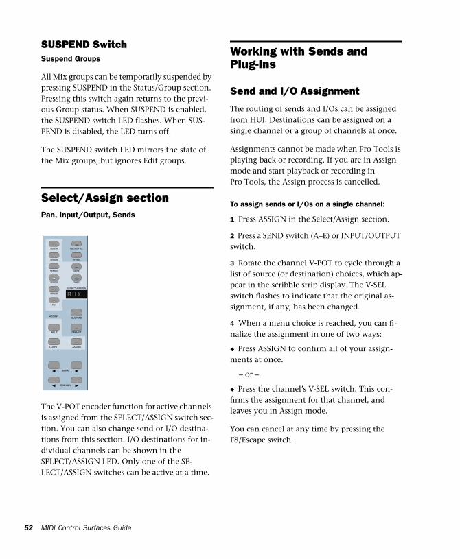
Select/Assign sectionPan, Input/Output, Sends
The V-POT encoder function for active channels is assigned from the SELECT/ASSIGN switch sec-tion. You can also change send or I/O destina-tions from this section. I/O destinations for in-dividual channels can be shown in the SELECT/ASSIGN LED. Only one of the SE-LECT/ASSIGN switches can be active at a time.
Working with Sends and Plug-Ins
Send and I/O Assignment
The routing of sends and I/Os can be assigned from HUI. Destinations can be assigned on a single channel or a group of channels at once.
Assignments cannot be made when Pro Tools is playing back or recording. If you are in Assign mode and start playback or recording in Pro Tools, the Assign process is cancelled.
To assign sends or I/Os on a single channel:
1 Press ASSIGN in the Select/Assign section.
2 Press a SEND switch (A–E) or INPUT/OUTPUT switch.
3 Rotate the channel V-POT to cycle through a list of source (or destination) choices, which ap-pear in the scribble strip display. The V-SEL switch flashes to indicate that the original as-signment, if any, has been changed.
4 When a menu choice is reached, you can fi-nalize the assignment in one of two ways:
◆ Press ASSIGN to confirm all of your assign-ments at once.
– or –
◆ Press the channel’s V-SEL switch. This con-firms the assignment for that channel, and leaves you in Assign mode.
You can cancel at any time by pressing the F8/Escape switch.
CHANNEL
BANK
SEND B
SEND C
SEND D
SEND E
PAN
SEND A REC/RDY ALL
BYPASS
MUTE
SHIFT
ASSIGN
DEFAULT
OUTPUT
INPUT
SUSPEND
SELECT-ASSIGN
ASSIGN
Chapter 3: Mackie HUI Control Surface 53
To assign the destinations of sends or I/Os on all channels:
1 Press ASSIGN in the Select/Assign section.
2 Press a SEND switch (A–E) or INPUT/OUTPUT switch.
3 Rotate a channel V-POT to cycle through a list of source (or destination) choices.
4 Press OPTION/ALL+ASSIGN or V-SEL to con-firm the assignments for all channels.
You can cancel at any time by pressing the F8/Escape switch.
To assign the destinations of sends or I/Os on a selection of channels:
1 Press ASSIGN in the Select/Assign section.
2 Press a SEND switch (A–E) or INPUT/OUTPUT switch.
3 Rotate a channel V-POT to cycle through a list of source (or destination) choices.
4 Press OPTION/ALL+SHIFT/ADD+ASSIGN or V-SEL to confirm the assignments for all se-lected channels.
You can cancel at any time by pressing the F8/Escape switch.
About I/O and SampleCell Labels
Instead of using the default I/O Label names for your audio inputs, outputs, busses, or Sample-Cell II cards, you can change them in Pro Tools to 4 character names that work better on the HUI. The I/O labels that you create in Pro Tools are mirrored in the HUI display.
You can also save these names as your default la-bels by clicking the Save As Default button in the Pro Tools I/O Labels dialog.
Pre-Fader or Post-Fader Switching for Sends
The V-POT V-SEL switch acts as a pre/post switch for the currently active send. As pre/post status is toggled, the channel’s scribble strip in-dicate “PRE” or “POST” (as long as the V-SEL switch is held down). Newly-created sends de-fault to post-fader (V-SEL switch LED is turned off).
This functionality is available while in Flip mode. Pre/post switching is not available when HUI is in Assign mode, or if the master MUTE switch is operating on the V-SEL switches, or while Pro Tools is playing or recording.
◆ To toggle a send pre-fader or post-fader, press the V-SEL switch on its channel.
◆ To toggle a send pre-fader or post-fader for all channels, press OPTION/ALL+V-SEL.
◆ To toggle a send pre-fader or post-fader for all selected channels, press OP-TION/ALL+SHIFT/ADD+V-SEL.
If a new send or I/O choice has been made and a channel’s V-SEL switch is flashing, you cannot swap banks or scroll channels. Once the new assignment has been con-firmed or cancelled, you can then do this.b
Refer to the Pro Tools Reference Guide for details on creating custom I/O Labels in Pro Tools.
MIDI Control Surfaces Guide54
Selecting and Editing Inserts and Plug-Ins There are three methods for selecting plug-in or Hardware I/O inserts for editing: using the IN-SERT switch with the DSP Edit/Assign display, using the INSERT switch with the SEND A–E switches, and by double-clicking the INSERT switch.
Selecting an Insert Using the DSP Edit/Assign section
In this method, the INSERT switch is used to be-gin the process, but the plug-in is selected in the DSP Edit/Assign section.
To select an insert using the DSP Edit/Assign display section menu:
1 Press a channel strip INSERT switch.
2 The names of the first four inserts for that channel appear in the DSP Edit/Assign display area. To access Insert #5, turn the SCROLL pot to go to the next page of inserts. The name of the last insert accessed during the current session flashes in the display. If no insert was accessed in the session, Insert #1 flashes.
3 To select a particular insert for editing, press the SELECT switch under an insert listed in the display.
4 If the insert is the currently flashing item in the display, double-click the channel’s INSERT switch, or press the DSP Edit/Assign section’s IN-SERT/PARAM switch to confirm the choice. To select an insert other than the currently flashing item, press the SELECT switch under the insert listed in the display.
5 If you have selected an insert assigned to a plug-in, its first page of parameters is displayed for editing. The INSERT/PARAM switch LED lights, indicating the display is in Parameter mode. Pressing the INSERT/PARAM switch tog-gles back to the Insert Display mode.
6 To edit additional pages of parameters in Pa-rameter mode, turn the SCROLL encoder pot to go to the next page.
The selected plug-in remains displayed until an-other insert is selected.
To reassign the insert to a different plug-in or Hardware I/O, refer to “Assigning Plug-Ins and Hardware I/O Inserts” on page 59.
Selecting a Send Using the SEND A–E Switches
Use the INSERT switch in conjunction with the SENDS A–E switches in the Select/Assign section to quickly access a send.
To select a send:
1 Press a channel strip INSERT switch.
2 Press one of the SEND A–E switches in the Se-lect/Assign section. The SENDS A–E switches correspond to Pro Tools Sends 1–5.
3 Send level and pre/post fader routing are now accessible for the send. Relative send levels are shown by the LED rings around each channel’s V-POT.
To reassign the send to a different output or bus, refer to “Send and I/O Assignment” on page 52.
Chapter 3: Mackie HUI Control Surface 55
Selecting an Insert by Double-Clicking the INSERT Switch
Double-clicking an INSERT switch directly ac-cesses the first assigned insert for editing. If the insert is assigned to a plug-in, the first control parameter page of the plug-in is displayed.
Plug-ins that are engaged are shown in lower-case letters; plug-ins that are bypassed are shown in uppercase letters.
To select an insert:
■ Double-click a channel strip INSERT switch. The channel’s first assigned insert is accessed for editing.
– or –
■ Double-click a channel strip INSERT switch multiple times to cycle through any inserts on the channel.
To assign a different plug-in or Hardware I/O to the insert, refer to “Assigning Plug-Ins and Hard-ware I/O Inserts” on page 59.
INSERT Switch Edit Focus and Bank Swapping
As channels are bank swapped using the Bank and Channel switches, the edit focus for the IN-SERT stays with its original channel, even though it may not be part of the currently dis-played bank of channel strips.
Send Level EditingThere are five SEND switches (labeled A–E), a SHIFT (“flip”) switch, and a PAN switch that let you edit channel pan, send level or send pan from the V-POT. The SEND A-E labels can apply to either the five sends or the five inserts, de-pending on function. The HUI Sends view mir-rors the on-screen sends view. If the current send is a stereo send, the scribble text for the send flashes.
To edit send levels:
1 Press one of the five SEND switches. The switch’s LED lights, and the SELECT/ASSIGN LED display shows the name of the activated switch.
2 Adjust the V-POT on an individual channel to edit levels for the selected send (a send must al-ready be assigned to the channel).
3 To show the destination of a particular send on all channels, press any master SEND switch (A–E) in the Select/Assign section. The destina-tions appear in each channel’s scribble strip.
Send Muting
When the master mute switch is lit, the V-SEL switches act as mute switches for the currently active send. In this mode, if a send is muted, its channel V-SEL switch LED lights. If the send is not muted, or if there is no active send (no des-tination), the LED remains unlit.
For an additional method of editing send level, send pan and send mute, see “Fader Flip mode” on page 56.
Keyboard shortcuts for ALL and ALL SE-LECTED channels using the shortcut mod-ifier keys do not function on send mutes.
MIDI Control Surfaces Guide56
Fader Flip modeNormally, the HUI channel faders control track volume while the rotary data encoders are used for pan, send level and send pan settings. In Flip mode, these functions are remapped.
To enter Flip mode:
■ Press SHIFT. The scribble strip displays “FLIP” and the SHIFT switch flashes.
For the currently selected SEND (A–E), send lev-els are mapped to the faders, send pan controls to the rotary encoders and send mutes to the channel MUTE switches. The names of the cur-rent sends are displayed in the scribble strips.
Send Pan in Flip mode
With stereo sends, the PAN switch lights when controlling left pan and flashes when control-ling right send pan. To change which send pan is being controlled, press the PAN switch.
Send Pre/Post in Flip mode
While in Flip mode, the V-SEL switch controls send pre/post operation (regardless of the cur-rent state of the master MUTE/PREPOST switch).
DEFAULT SwitchQuickMode
This switch returns a channel strip’s faders and V-POTS to their default settings. The default set-tings for fader position is “0” (or unity) gain; for pan, the default is centered.
The DEFAULT switch obeys grouped behavior. To temporarily disable grouped behavior, press CTRL/CLUTCH while pressing DEFAULT, or sus-pend groups.
To return a channel strip fader to its default setting:
■ Press DEFAULT+ the channel strip’s SELECT switch.
To return all channel strip faders to their default settings:
■ Press OPTION/ALL+DEFAULT+ any channel strip’s SELECT switch.
To return all selected channel strip faders to their default settings:
■ Press OPTION/ALL+SHIFT/ADD+DEFAULT+ any selected channel strip’s SELECT switch.
To return a channel strip’s send level or pan to its default setting:
1 Press a SEND (A–E) or PAN switch in the Se-lect/Assign section.
2 Press DEFAULT+ any channel strip’s V-SEL switch.
To return all channel strip send levels or pans to their default settings:
■ Press OPTION/ALL+DEFAULT+ any channel strip’s V-SEL switch.
To return all selected channel strip send levels or pans to their default settings:
■ Press OPTION/ALL+SHIFT/ADD+DEFAULT+ any selected channel strip’s V-SEL switch.
DEFAULT
Chapter 3: Mackie HUI Control Surface 57
To return a Plug-In to its default setting:
■ Press DEFAULT+ the COMPARE switch in the DSP EDIT/ASSIGN area.
The plug-in returns to either the Factory Setting or the User Setting default, depending upon which is selected in the “Settings Preference” in the Plug-In Librarian pop-up menu.
Working with Plug-Ins: Using the DSP Edit/Assign Section
This section is used to assign plug-ins and Hard-ware I/O inserts, and to edit plug-in parameters.
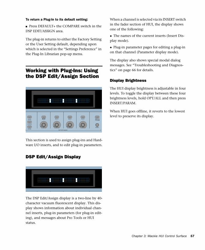
DSP Edit/Assign Display
The DSP Edit/Assign display is a two-line by 40-character vacuum fluorescent display. This dis-play shows information about individual chan-nel inserts, plug-in parameters (for plug-in edit-ing), and messages about Pro Tools or HUI status.
When a channel is selected via its INSERT switch in the fader section of HUI, the display shows one of the following:
◆ The names of the current inserts (Insert Dis-play mode).
◆ Plug-in parameter pages for editing a plug-in on that channel (Parameter display mode).
The display also shows special modal dialog messages. See “Troubleshooting and Diagnos-tics” on page 66 for details.
Display Brightness
The HUI display brightness is adjustable in four levels. To toggle the display between these four brightness levels, hold OPT/ALL and then press INSERT/PARAM.
When HUI goes offline, it reverts to the lowest level to preserve its display.
SELECT SELECT SELECT
SCROLL
DSP EDIT/ASSIGN
INSERTPARAM
SELECT SELECT
COMPARE
ASSIGN
BYPASS
MIDI Control Surfaces Guide58
DSP SELECT Switches and V-POT Encoders
Under the HUI display, there are four sets of SE-LECT switches and V-POT encoders. The SE-LECT switch and V-POT encoder have different functions depending on whether the display is currently in Insert display mode or Parameter display mode:
◆ In Insert mode, the SELECT switch is used to select an insert for editing or assignment. The V-POT encoder is used in Assign mode to choose from a list of plug-ins or Hardware I/O pairs for assignment.
◆ In Parameter mode, these controls are used for plug-in editing. The four switches and four en-coders represent the controls in a plug-in inter-face. Controls are mapped to pages (or logical groups) of controls. Generally, the switches con-trol switched parameters (for example, EQ band in/out controls). The encoders control continu-ously variable parameters (such as gain), or pa-rameters that contain several discrete choices (such as choosing different reverb algorithms in a reverb plug-in).
Rotary Knob Settings
Many of the rotary encoders on the HUI can op-erate in fixed or velocity-sensitive modes. In fixed mode, a single complete turn of the knob goes through the entire range of values, independent of how quickly you turn it. When moving rotary encoders in fixed mode, you can hold ALT/FINE
for finer control of setting values. In velocity-sen-sitive mode, the speed at which you sweep through encoded values depends on how quickly you turn the knob.
The rotary encoders on the HUI channel strips (which are used for adjusting send levels and pan controls) operate in fixed mode only.
The rotary encoders in the DSP Edit/Assign sec-tion can behave in a fixed or velocity-sensitive manner (the default setting is velocity sensitive). To toggle the rotary encoder mode, press the F5 switch.
Automation Mode Indicator
If a plug-in parameter is enabled for automation (Touch, Latch, or Write), the 6 o’clock position LED (located in the bottom center of the V-POT LED collar) flashes. If automation data for the plug-in control is being recorded, the 6 o’clock LED lights.
Touch Time-Out for V-POT Editing
Since V-POTs are not touch-sensitive, when you stop moving them, Pro Tools continues to write automation for the Touch Timeout period. After the Touch Timeout period, writing of automa-tion stops and the automation data returns to its previous automation value.
In addition, you can stop the writing of automa-tion by stopping the Pro Tools transport.
You may want to use Latch mode to record plug-in parameter automation changes using a V-POT. With Latch Automation, you can begin writing automation (by moving a V-POT) at any point during an automation pass, and the V-POT will not time out in the middle of the pass because you are not moving it.
SELECTSELECT
Refer to the Pro Tools Reference Guide for details on automating plug-ins.
Chapter 3: Mackie HUI Control Surface 59
Assigning Plug-Ins and Hardware I/O Inserts
ASSIGN Switch
You can assign plug-ins or Hardware I/O inserts from HUI.
NOTE: Assignments cannot be made when Pro Tools is playing back or recording. If you are in Assign mode and start playback or recording in Pro Tools, the ASSIGN process is cancelled.
To assign a Plug-In or Hardware I/O on a single channel:
1 Press the INSERT switch on the channel. The INSERT switch LED lights, the associated track name is outlined in red in the Mix window.
2 Press the ASSIGN switch in the DSP Edit/As-sign section (not in the Select/Assign section). The ASSIGN switch LED flashes.
If you are in Assign mode and you press the IN-SERT switch on another channel strip, the As-sign process is cancelled.
3 Under the insert that you want to assign, ro-tate the V-POT encoder to choose a plug-in or Hardware I/O pairs.
When you rotate the V-POT encoder, its accom-panying SELECT switch flashes, indicating the insert is being assigned or edited. (The switch will not flash if the assignment is unchanged.)
4 When a menu choice is reached, you can con-firm the assignment in one of two ways:
• Press the ASSIGN switch to confirm all of your assignments at once.
• Press the SELECT switch beneath the insert in the display to confirm your choice. This con-firms the assignment for that insert, and leaves you in Assign mode.
You can cancel at any time by pressing the F8/Escape switch.
5 Press the SELECT switch directly under a newly assigned plug-in, and its first control pa-rameter page appears in the display for editing. You can switch between viewing insert selec-tions and parameter pages by pressing the IN-SERT/PARAM switch.
To assign a Plug-In or Hardware I/O on all channels:
1 Follow steps 1–3 above.
2 Press OPTION/ALL+ASSIGN in the DSP Edit/Assign area (or the SELECT switch beneath the insert that you are editing).
To assign a Plug-In or Hardware I/O on all selected channels:
1 Select channels by holding down SHIFT/ADD and pressing SELECT on the channels.
2 Press ASSIGN in the DSP Edit/Assign section.
3 Follow steps 1–3 above.
4 Press OPTION/ALL+SHIFT/ADD+ASSIGN in the DSP Edit/Assign section.
ASSIGN

MIDI Control Surfaces Guide60
Editing Plug-In Parameters When a plug-in insert is selected for editing, its first page of control parameters is shown in the HUI display. Individual parameters can then be edited using the switches and V-POTs in the DSP Edit/Assign section.
When the HUI is used to edit plug-in settings, the associated track name is outlined in red in the Pro Tools Mix window.
To edit an assigned Plug-In on a channel:
1 Select a plug-in insert using one of the three methods described in “Selecting and Editing In-serts and Plug-Ins” on page 54. The IN-SERT/PARAM switch LED is lit, indicating the display is in Parameter mode.
– or –
If you just finished assigning a plug-in on an in-sert, press the INSERT/PARAM switch LED to en-able Parameter mode (LED is lit), if necessary.
2 Rotate the SCROLL encoder pot to find the plug-in parameter you want to edit.
3 Do one of the following:
◆ If the parameter is a switched parameter press the SELECT switch under the parameter in the display to toggle its state.
◆ If the parameter is continuously variable, or has stepped values, rotate the V-POT encoder under the parameter in the display to adjust its setting. The LED ring around the V-POT indi-cates parameter settings or levels. Numeric pa-rameter values are shown in the display. If a parameter amount exceeds four digits, the end of the parameter value string is truncated.
The rotary encoders in the DSP Edit/Assign sec-tion can behave in a velocity-sensitive or fixed manner. To toggle the rotary encoder mode, press the F5 switch.
DSP Parameter Value Display
When in parameters view, holding the OPTION key while changing a DSP parameter value via the encoder causes the value to be temporarily displayed as a full 9 character value in the DSP scribble display.
COMPARE Switch
Compare edited plug-in parameter settings to the original settings with the COMPARE switch, which mirrors the Compare button in a Pro Tools plug-in.
The COMPARE switch will function only in plug-ins that are visible on-screen. Use the ALT switch to open the currently active plug-in.
COMPARE
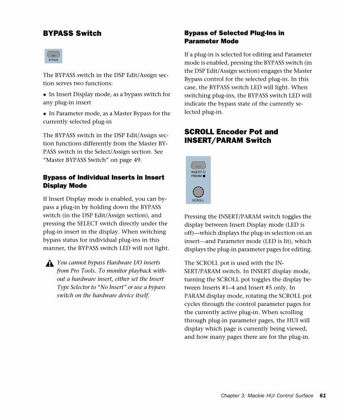
Chapter 3: Mackie HUI Control Surface 61
BYPASS Switch
The BYPASS switch in the DSP Edit/Assign sec-tion serves two functions:
◆ In Insert Display mode, as a bypass switch for any plug-in insert
◆ In Parameter mode, as a Master Bypass for the currently selected plug-in
The BYPASS switch in the DSP Edit/Assign sec-tion functions differently from the Master BY-PASS switch in the Select/Assign section. See “Master BYPASS Switch” on page 49.
Bypass of Individual Inserts in Insert Display Mode
If Insert Display mode is enabled, you can by-pass a plug-in by holding down the BYPASS switch (in the DSP Edit/Assign section), and pressing the SELECT switch directly under the plug-in insert in the display. When switching bypass status for individual plug-ins in this manner, the BYPASS switch LED will not light.
Bypass of Selected Plug-Ins in Parameter Mode
If a plug-in is selected for editing and Parameter mode is enabled, pressing the BYPASS switch (in the DSP Edit/Assign section) engages the Master Bypass control for the selected plug-in. In this case, the BYPASS switch LED will light. When switching plug-ins, the BYPASS switch LED will indicate the bypass state of the currently se-lected plug-in.
SCROLL Encoder Pot and INSERT/PARAM Switch
Pressing the INSERT/PARAM switch toggles the display between Insert Display mode (LED is off)—which displays the plug-in selection on an insert—and Parameter mode (LED is lit), which displays the plug-in parameter pages for editing.
The SCROLL pot is used with the IN-SERT/PARAM switch. In INSERT display mode, turning the SCROLL pot toggles the display be-tween Inserts #1–4 and Insert #5 only. In PARAM display mode, rotating the SCROLL pot cycles through the control parameter pages for the currently active plug-in. When scrolling through plug-in parameter pages, the HUI will display which page is currently being viewed, and how many pages there are for the plug-in.
You cannot bypass Hardware I/O inserts from Pro Tools. To monitor playback with-out a hardware insert, either set the Insert Type Selector to “No Insert” or use a bypass switch on the hardware device itself.
BYPASS
SCROLL
INSERTPARAM
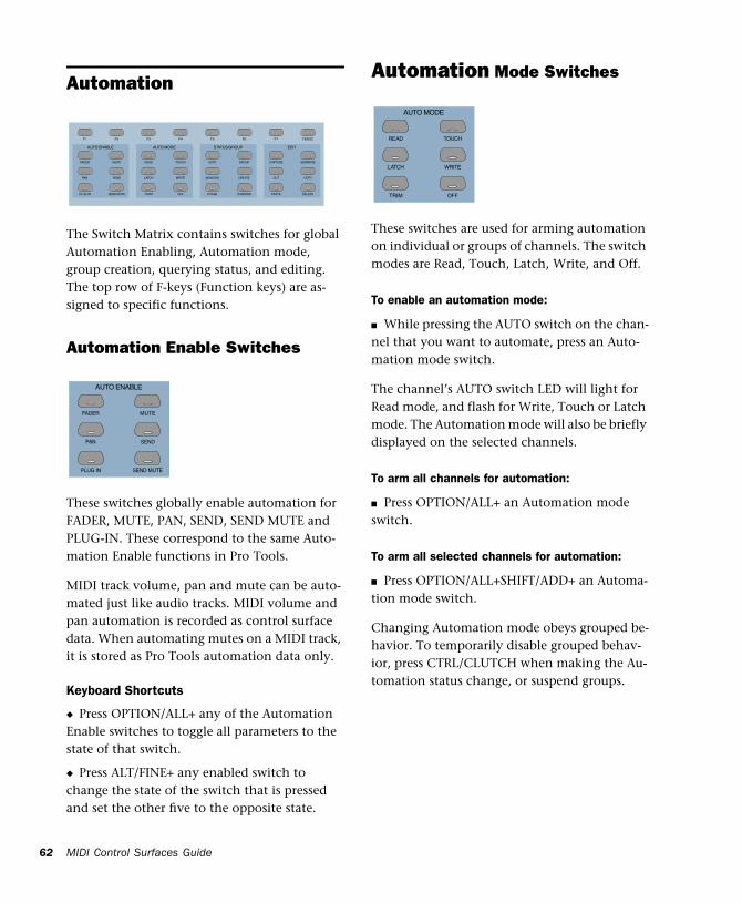
MIDI Control Surfaces Guide62
Automation
The Switch Matrix contains switches for global Automation Enabling, Automation mode, group creation, querying status, and editing. The top row of F-keys (Function keys) are as-signed to specific functions.
Automation Enable Switches
These switches globally enable automation for FADER, MUTE, PAN, SEND, SEND MUTE and PLUG-IN. These correspond to the same Auto-mation Enable functions in Pro Tools.
MIDI track volume, pan and mute can be auto-mated just like audio tracks. MIDI volume and pan automation is recorded as control surface data. When automating mutes on a MIDI track, it is stored as Pro Tools automation data only.
Keyboard Shortcuts
◆ Press OPTION/ALL+ any of the Automation Enable switches to toggle all parameters to the state of that switch.
◆ Press ALT/FINE+ any enabled switch to change the state of the switch that is pressed and set the other five to the opposite state.
Automation Mode Switches
These switches are used for arming automation on individual or groups of channels. The switch modes are Read, Touch, Latch, Write, and Off.
To enable an automation mode:
■ While pressing the AUTO switch on the chan-nel that you want to automate, press an Auto-mation mode switch.
The channel’s AUTO switch LED will light for Read mode, and flash for Write, Touch or Latch mode. The Automation mode will also be briefly displayed on the selected channels.
To arm all channels for automation:
■ Press OPTION/ALL+ an Automation mode switch.
To arm all selected channels for automation:
■ Press OPTION/ALL+SHIFT/ADD+ an Automa-tion mode switch.
Changing Automation mode obeys grouped be-havior. To temporarily disable grouped behav-ior, press CTRL/CLUTCH when making the Au-tomation status change, or suspend groups.
F6 F7F1 F2 F3 F4 F5 F8/ESC
AUTO
PLUG IN SEND MUTE TRIM OFF PHASE SUSPEND
PAN SEND LATCH WRITE MONITOR CREATE
PASTE
CUT
FADER MUTE READ TOUCH GROUP CAPTURE
DELETE
COPY
SEPARATE
AUTO ENABLE AUTO MODE EDITSTATUS/GROUP
PLUG IN SEND MUTE
PAN SEND
FADER MUTE
AUTO ENABLE
TRIM OFF
LATCH WRITE
READ TOUCH
AUTO MODE
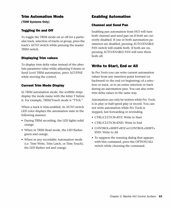
Chapter 3: Mackie HUI Control Surface 63
Trim Automation Mode(TDM Systems Only)
Toggling On and Off
To toggle the TRIM mode on or off for a partic-ular track, selection of tracks or group, press the track’s AUTO switch while pressing the master TRIM switch.
Displaying Trim values
To display trim delta value instead of the abso-lute parameter value while adjusting Volume or Send Level TRIM automation, press ALT/FINE while moving the control.
Current Trim Mode Display
In TRIM automation mode, the scribble strips display the mode name with the letter T before it. For example, TRIM/Touch mode is “TTch.”
When a track is trim-enabled, its AUTO switch LED color displays the automation state in the following manner:
• During TRIM recording, the LED lights solid orange.
• When in TRIM Read mode, the LED flashes green and orange.
• When in any recordable Automation mode (i.e. Trim Write, Trim Latch, or Trim Touch), the LED flashes red and orange.
Enabling Automation
Channel and Send Pan
Enabling pan automation from HUI will turn both channel and send pan on if both are cur-rently disabled. If one or both automation pa-rameters are disabled, pressing AUTO/ENABLE PAN switch will enable both. If both are on, pressing AUTO/ENABLE PAN will turn them both off.
Write to Start, End or All
In Pro Tools you can write current automation values from any insertion point forward (or backward) to the end (or beginning) of a selec-tion or track, or to an entire selection or track during an automation pass. You can also write trim delta values in the same way.
Automation can only be written while Pro Tools is in play or half-speed play or record. You can-not write automation while Pro Tools is stopped, fast forwarding or rewinding.
• CTRL/CLUTCH+RTZ: Write to Start
• CTRL/CLUTCH+END: Write to End
• CONTROL+SHIFT+RTZ or CONTROL+SHIFT+ END: Write to All
• To suppress the warning dialog that appears with this command, press the OPTION/ALL switch while choosing the command.
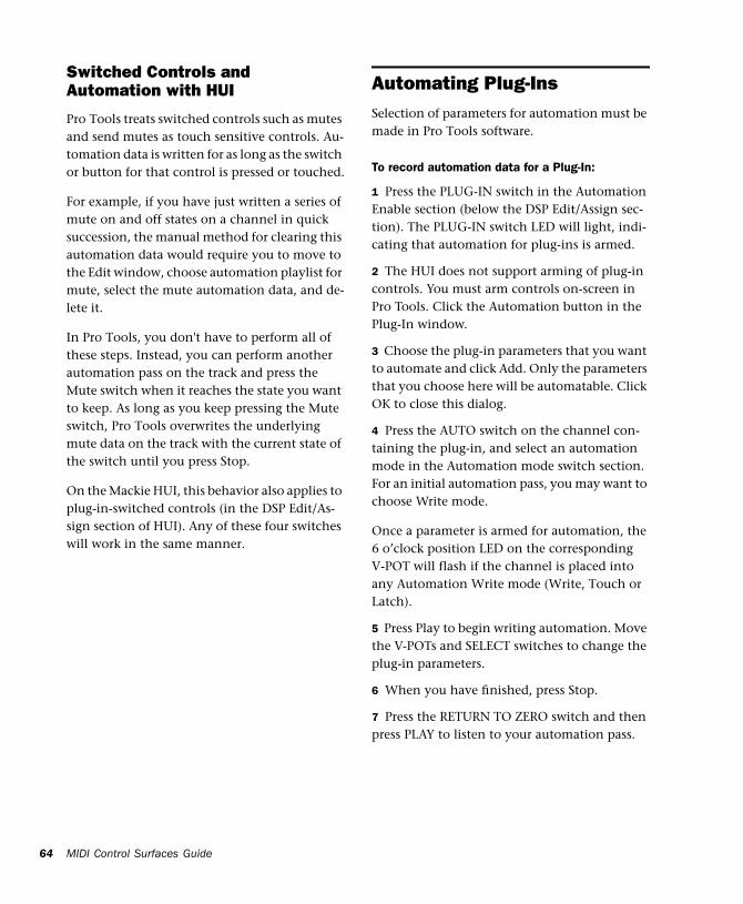
MIDI Control Surfaces Guide64
Switched Controls and Automation with HUI
Pro Tools treats switched controls such as mutes and send mutes as touch sensitive controls. Au-tomation data is written for as long as the switch or button for that control is pressed or touched.
For example, if you have just written a series of mute on and off states on a channel in quick succession, the manual method for clearing this automation data would require you to move to the Edit window, choose automation playlist for mute, select the mute automation data, and de-lete it.
In Pro Tools, you don't have to perform all of these steps. Instead, you can perform another automation pass on the track and press the Mute switch when it reaches the state you want to keep. As long as you keep pressing the Mute switch, Pro Tools overwrites the underlying mute data on the track with the current state of the switch until you press Stop.
On the Mackie HUI, this behavior also applies to plug-in-switched controls (in the DSP Edit/As-sign section of HUI). Any of these four switches will work in the same manner.
Automating Plug-InsSelection of parameters for automation must be made in Pro Tools software.
To record automation data for a Plug-In:
1 Press the PLUG-IN switch in the Automation Enable section (below the DSP Edit/Assign sec-tion). The PLUG-IN switch LED will light, indi-cating that automation for plug-ins is armed.
2 The HUI does not support arming of plug-in controls. You must arm controls on-screen in Pro Tools. Click the Automation button in the Plug-In window.
3 Choose the plug-in parameters that you want to automate and click Add. Only the parameters that you choose here will be automatable. Click OK to close this dialog.
4 Press the AUTO switch on the channel con-taining the plug-in, and select an automation mode in the Automation mode switch section. For an initial automation pass, you may want to choose Write mode.
Once a parameter is armed for automation, the 6 o’clock position LED on the corresponding V-POT will flash if the channel is placed into any Automation Write mode (Write, Touch or Latch).
5 Press Play to begin writing automation. Move the V-POTs and SELECT switches to change the plug-in parameters.
6 When you have finished, press Stop.
7 Press the RETURN TO ZERO switch and then press PLAY to listen to your automation pass.
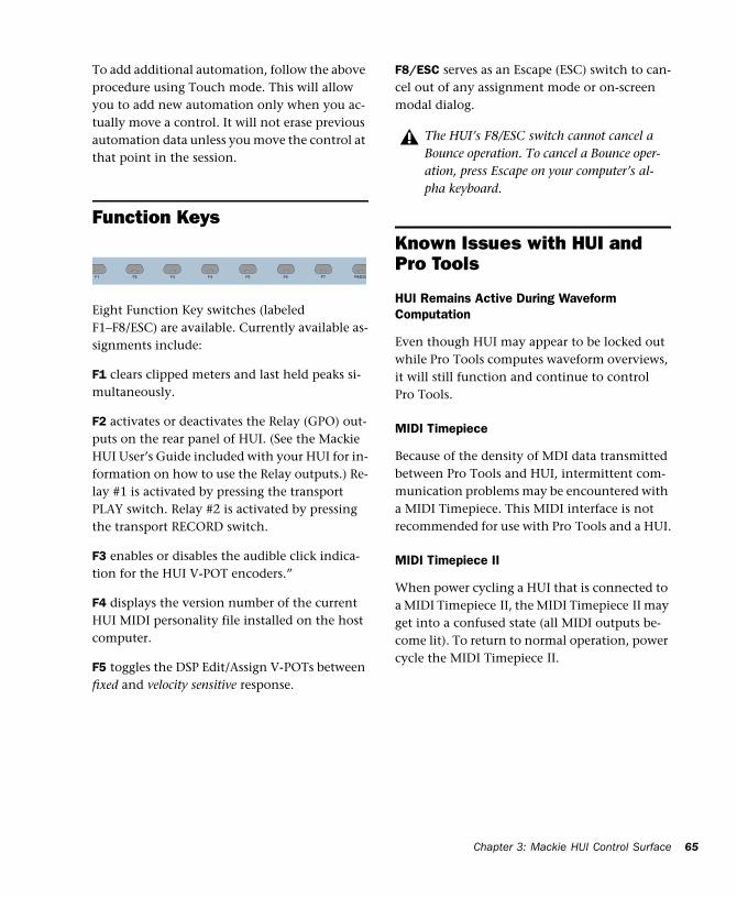
Chapter 3: Mackie HUI Control Surface 65
To add additional automation, follow the above procedure using Touch mode. This will allow you to add new automation only when you ac-tually move a control. It will not erase previous automation data unless you move the control at that point in the session.
Function Keys
Eight Function Key switches (labeled F1–F8/ESC) are available. Currently available as-signments include:
F1 clears clipped meters and last held peaks si-multaneously.
F2 activates or deactivates the Relay (GPO) out-puts on the rear panel of HUI. (See the Mackie HUI User’s Guide included with your HUI for in-formation on how to use the Relay outputs.) Re-lay #1 is activated by pressing the transport PLAY switch. Relay #2 is activated by pressing the transport RECORD switch.
F3 enables or disables the audible click indica-tion for the HUI V-POT encoders.”
F4 displays the version number of the current HUI MIDI personality file installed on the host computer.
F5 toggles the DSP Edit/Assign V-POTs between fixed and velocity sensitive response.
F8/ESC serves as an Escape (ESC) switch to can-cel out of any assignment mode or on-screen modal dialog.
Known Issues with HUI and Pro Tools
HUI Remains Active During Waveform Computation
Even though HUI may appear to be locked out while Pro Tools computes waveform overviews, it will still function and continue to control Pro Tools.
MIDI Timepiece
Because of the density of MDI data transmitted between Pro Tools and HUI, intermittent com-munication problems may be encountered with a MIDI Timepiece. This MIDI interface is not recommended for use with Pro Tools and a HUI.
MIDI Timepiece II
When power cycling a HUI that is connected to a MIDI Timepiece II, the MIDI Timepiece II may get into a confused state (all MIDI outputs be-come lit). To return to normal operation, power cycle the MIDI Timepiece II.
F6 F7F1 F2 F3 F4 F5 F8/ESC
The HUI’s F8/ESC switch cannot cancel a Bounce operation. To cancel a Bounce oper-ation, press Escape on your computer’s al-pha keyboard.
MIDI Control Surfaces Guide66
Troubleshooting and DiagnosticsHUI provides a built-in, comprehensive diag-nostic test upon startup. You can confirm that your HUI is fully functional by running this test.
Startup Test
As HUI initializes during startup, it goes through a series of diagnostics. Once these internal tests are complete, HUI displays a message and its current firmware version.
In addition, HUI has a series of built-in tests de-signed to let you confirm that it is working properly. HUI, Pro Tools, your MIDI interface and setup, AMS (Mac OS X only) or OMS (Mac OS 9 only), and your computer all work together to create a unified system. These diagnostics al-low you to confirm that HUI is operating prop-erly.
To place HUI in diagnostic mode:
1 Immediately after turning on the power switch, press the OPTION/ALL and SHIFT/ADD switches.
2 In diagnostic mode, all LEDs on the HUI con-trol panel should be lit. Take notice of any LEDs that fail to illuminate.
3 Rotate the MASTER VOLUME pot in the Ana-log Monitoring section to control the speed of the channel fader travel. Make sure that the channel faders are responding to servo control.
4 Press Footswitch #2 to exit the test routine. If you do not have a footswitch connected, power down HUI, wait a few moments, and then power on HUI.
5 Once the initial startup routine is successfully completed, HUI will display “Welcome to HUI” in its display.
With the comprehensive diagnostics included in your HUI, you can determine definitively whether or not HUI (on its own) is working properly.
◆ Contact Mackie Designs if your problem lies with your HUI hardware.
◆ Contact Digidesign if you have problems with Pro Tools software or MIDI services.
When calling Mackie or Digidesign Customer Support, be sure to indicate that you are using a HUI with Pro Tools. Provide the technician with a report of your problems and results of the di-agnostic tests.
MIDI Monitor Mode
MIDI Monitor mode displays the last several MIDI messages transmitted or received by HUI. The data appears in hexadecimal code on its dis-play. To gain access to MIDI Monitor mode, press the F4 switch while pressing the OP-TION/ALL switch. To leave MIDI monitor mode, press the OPTION/ALL switch and press the F4 switch again.