Embed Size (px)
Citation preview

world of innovation
MacroPower 400 – 2000 tThe compact large machine
2
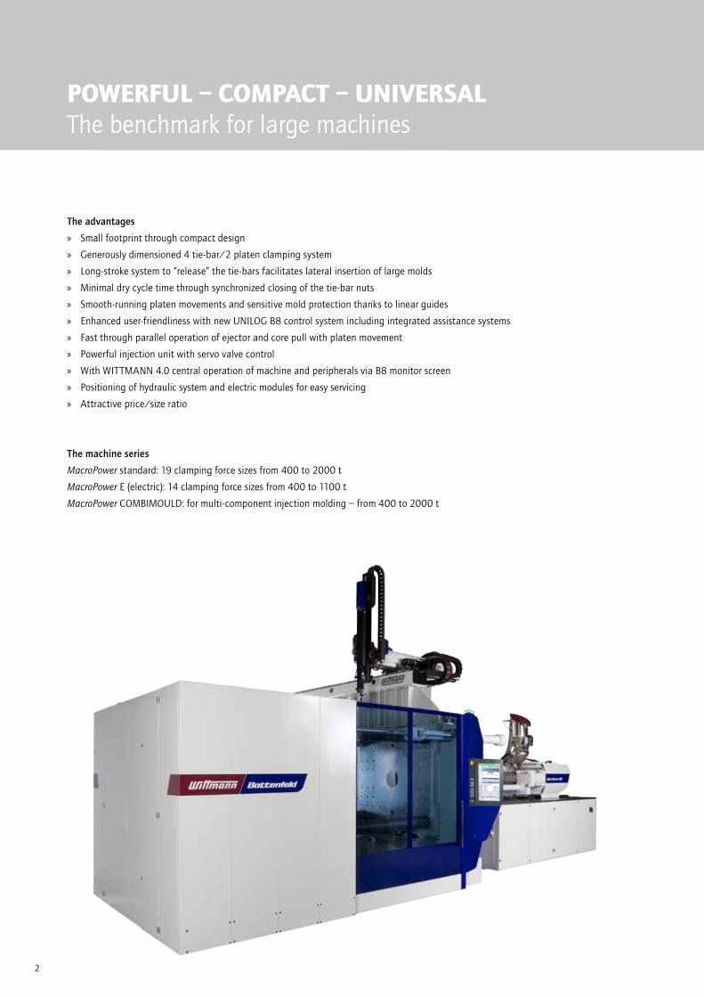
POWERFUL – COMPACT – UNIVERSALThe benchmark for large machines
The advantages
Small footprint through compact design
Generously dimensioned 4 tie-bar/2 platen clamping system
Long-stroke system to “release” the tie-bars facilitates lateral insertion of large molds
Minimal dry cycle time through synchronized closing of the tie-bar nuts
Smooth-running platen movements and sensitive mold protection thanks to linear guides
Enhanced user-friendliness with new UNILOG B8 control system including integrated assistance systems
Fast through parallel operation of ejector and core pull with platen movement
Powerful injection unit with servo valve control
With WITTMANN 4.0 central operation of machine and peripherals via B8 monitor screen
Positioning of hydraulic system and electric modules for easy servicing
Attractive price/size ratio
The machine series
MacroPower standard: 19 clamping force sizes from 400 to 2000 t
MacroPower E (electric): 14 clamping force sizes from 400 to 1100 t
MacroPower COMBIMOULD: for multi-component injection molding – from 400 to 2000 t
3
MacroPowerThe system highlights
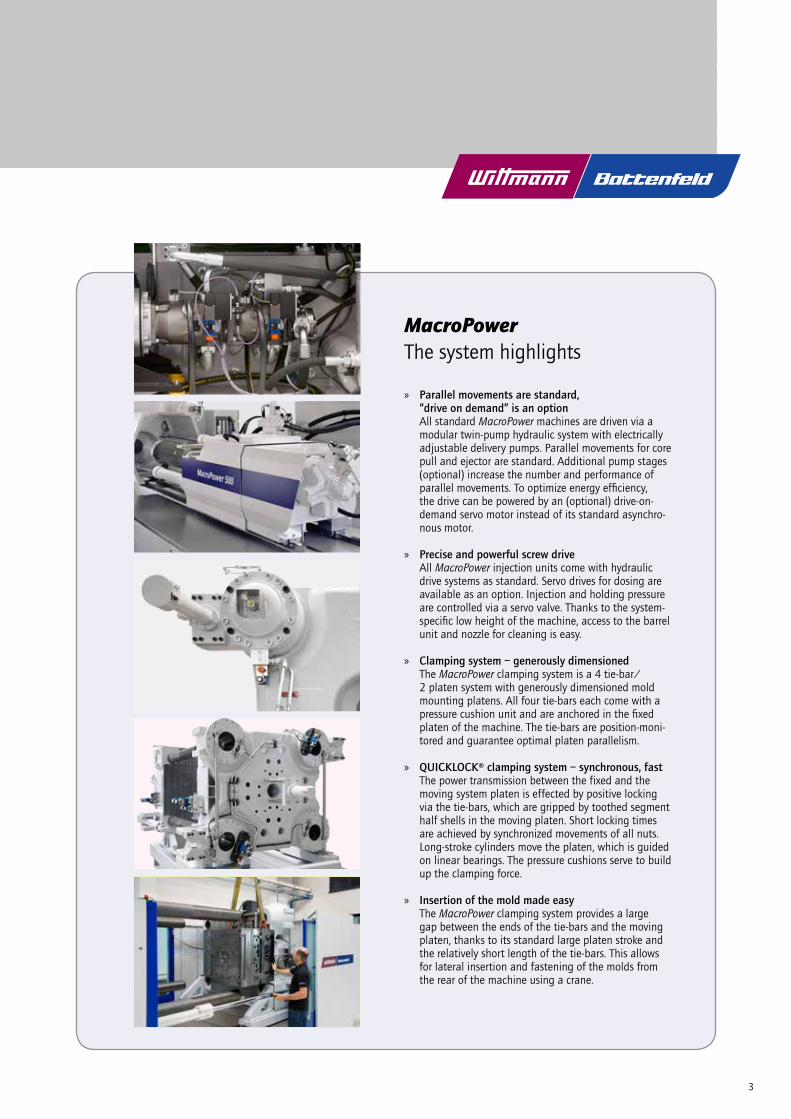
Parallel movements are standard, “drive on demand” is an option
All standard MacroPower machines are driven via a modular twin-pump hydraulic system with electrically adjustable delivery pumps. Parallel movements for core pull and ejector are standard. Additional pump stages (optional) increase the number and performance of parallel movements. To optimize energy efficiency, the drive can be powered by an (optional) drive-on-demand servo motor instead of its standard asynchro-nous motor.
Precise and powerful screw drive All MacroPower injection units come with hydraulic
drive systems as standard. Servo drives for dosing are available as an option. Injection and holding pressure are controlled via a servo valve. Thanks to the system-specific low height of the machine, access to the barrel unit and nozzle for cleaning is easy.
Clamping system – generously dimensioned The MacroPower clamping system is a 4 tie-bar/ 2 platen system with generously dimensioned mold mounting platens. All four tie-bars each come with a pressure cushion unit and are anchored in the fixed platen of the machine. The tie-bars are position-moni-tored and guarantee optimal platen parallelism.
QUICKLOCK® clamping system – synchronous, fast The power transmission between the fixed and the moving system platen is effected by positive locking via the tie-bars, which are gripped by toothed segment half shells in the moving platen. Short locking times are achieved by synchronized movements of all nuts. Long-stroke cylinders move the platen, which is guided on linear bearings. The pressure cushions serve to build up the clamping force.
Insertion of the mold made easy The MacroPower clamping system provides a large gap between the ends of the tie-bars and the moving platen, thanks to its standard large platen stroke and the relatively short length of the tie-bars. This allows for lateral insertion and fastening of the molds from the rear of the machine using a crane.

4
CLAMPING UNITHigh functionality with ample mold space
Large and flexible The extensive MacroPower system construction kit offers a wide
range of combination options from numerous clamping force variants with matching distances between tie-bars, in both standard and XL versions.
Sensitive and precise In the MacroPower clamping system, the tie-bars are only used
for the force transmission between the mold platens. The moving platen is mounted on a carriage, which travels on high-precision linear bearings along the machine frame. The minimal rolling friction in the linear bearings is the prerequisite for highly sensi-tive mold protection and high cleanless.
Fast and synchronized The QUICKLOCK® locking system between the tie-bars and the moving platen consists of four synchronized tooth segment nuts, which are integrated in the moving platen to minimize the machine’s footprint.
Compact design for minimal footprintThe integrated tie-bar nuts and short tie-bars offer two advan-tages: short footprint and simultaneously free space for lateral mold insertion.
Symmetrical and powerful The moving platen is driven by two diagonally positioned travel-
ing cylinders designed for high speed. The traveling drive in combination with a hydraulic differential gear system provides the basic conditions for high speed, precision in movements and power.

5
INJECTION UNITServo-controlled and precise
Everything to ensure series consistency– All screws come with a 22:1 L/D ratio.– Direct drive via slow-running hydro motor (servo motor available as an option)– Maximum repeatability through servo valve cl control for
injection and holding pressure– Moment-free nozzle contact through axial positioning of the
traveling cylinders– Wide range of suitable screws and barrels for various process
technologies available– WITTMANN BATTENFELD HiQ software modules (optional)
offer extensive facilities for compensating environmental fac-tors such as fluctuations in temperature, moisture, regrind or masterbatch content.
Extremely easy operation and flexibility– Free access to the injection unit for easy material feeding,
machine setting and servicing– Maximum maintenance-friendliness thanks to compact design
and free accessibility
Anti-wear optionsIn addition to the premium-quality standard equipment, an extensive range of options is available to provide extra anti-wear and/or anti-corrosion protection. Predefined option packages and a selection matrix facilitate the selection of the right plasticizing unit.
6
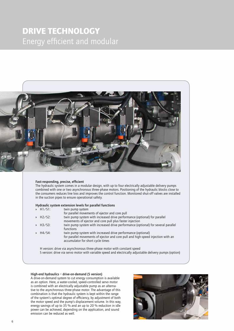
DRIVE TECHNOLOGYEnergy efficient and modular
Fast-responding, precise, efficientThe hydraulic system comes in a modular design, with up to four electrically adjustable delivery pumps combined with one or two asynchronous three-phase motors. Positioning of the hydraulic blocks close to the consumers reduces line loss and improves the control function. Monitored shut-off valves are installed in the suction pipes to ensure operational safety.
Hydraulic system extension levels for parallel functions H1/S1: twin pump system
for parallel movements of ejector and core pull H2/S2: twin pump system with increased drive performance (optional) for parallel
movements of ejector and core pull plus faster injection H3/S3: twin pump system with increased drive performance (optional) for several parallel
functions H4/S4: twin pump system with increased drive performance (optional)
for parallel movements of ejector and core pull and high-speed injection with an accumulator for short cycle times
H version: drive via asynchronous three-phase motor with constant speed S version: drive via servo motor with variable speed and electrically adjustable delivery pumps (option)
High-end hydraulics – drive-on-demand (S version)A drive-on-demand system to cut energy consumption is available as an option. Here, a water-cooled, speed-controlled servo motor is combined with an electrically adjustable pump as an alterna-tive to the asynchronous three-phase motor. The advantage of this combination is that the hydraulic system is kept within the range of the system’s optimal degree of efficiency, by adjustment of both the motor speed and the pump’s displacement volume. In this way, energy savings of up to 35 % and an up to 20 % reduction in idle power can be achieved, depending on the application, and sound emission can be reduced as well.

7
PRODUCTION CELLCustomized configuration
WITTMANN BATTENFELD injection molding machines come with a flexibly adjustable basic modular design. From this basis, the machine can be extended with a wide range of automation equipment into a production cell. This includes primarily devices for fast mold change, fast coupling of complex media connections and the automation of finished parts handling.
MacroPower automation options: “Handling robot automation module“ with linear or articulated arm robot and
logistics peripherals
Mold clamping systemsBoth hydraulic and magnetic clamping systems are available including all safety monitoring features, if required combined with roller conveyor units for lateral mold transfer.
Automatic mold change system as fixed carriage and pre-heating station or as a flexibly movable carriage system with docking interface
Combination with WITTMANN peripheral units via WITTMANN 4.0 Temperature control or cooling, material feeding, coloring and drying

8
UNILOG B8Complex matters simplified
UNILOG B8Highlights
Operating logic with a high degree of self-explanation, similar to
modern communication devices
2 major operating principles– Operating/movement functions via tactile keys– Process functions on touch screen (access via RFID,
key card or key ring)
Process visualization via 21.5” touch screen display (full HD), pivoting laterally
New screen functions– Uniform layout for all WITTMANN units– Recognition of gestures (wiping and zooming by
finger movements)– Container function – split screen for sub-functions
and programs
Status visualization uniform signaling system across the entire
WITTMANN group– Headline on the screen with colored status bars
and pop-up menus– ambiLED-display on machine
Operator assistance– QuickSetup: process parameter setting assistant
using an integrated material database and a simple query system to retrieve molded part data with machine settings pre-selection
– Extensive help library integrated
The new UNILOG B8 machine control system is the WITTMANN BATTENFELD solution to facilitate the operation of complex processes for human operators. For this purpose, the integrated industrial PC has been equipped with an enlarged intuitive touch screen operator terminal. The visualization screen is the interface to the new Windows® 10 loT operating system, which offers extensive process control functions. Next to the pivo-table monitor screen, a connected panel/handset is mounted on the machine’s central console.
9
9:38
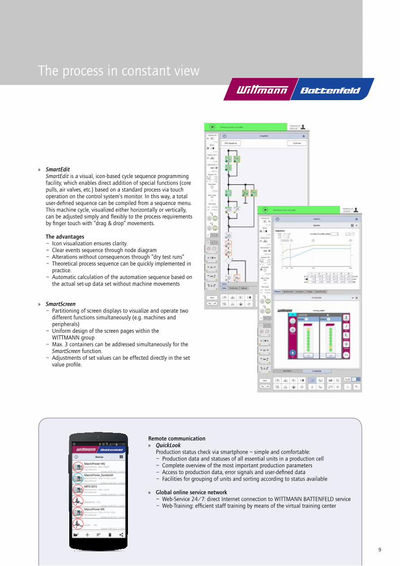
The process in constant view
SmartEdit SmartEdit is a visual, icon-based cycle sequence programming
facility, which enables direct addition of special functions (core pulls, air valves, etc.) based on a standard process via touch operation on the control system’s monitor. In this way, a total user-defined sequence can be compiled from a sequence menu. This machine cycle, visualized either horizontally or vertically, can be adjusted simply and flexibly to the process requirements by finger touch with “drag & drop” movements.
The advantages– Icon visualization ensures clarity.– Clear events sequence through node diagram– Alterations without consequences through “dry test runs”– Theoretical process sequence can be quickly implemented in
practice. – Automatic calculation of the automation sequence based on
the actual set-up data set without machine movements
SmartScreen– Partitioning of screen displays to visualize and operate two
different functions simultaneously (e.g. machines and peripherals)– Uniform design of the screen pages within the
WITTMANN group– Max. 3 containers can be addressed simultaneously for the
SmartScreen function.– Adjustments of set values can be effected directly in the set
value profile.
Remote communication QuickLook
Production status check via smartphone – simple and comfortable:– Production data and statuses of all essential units in a production cell– Complete overview of the most important production parameters– Access to production data, error signals and user-defined data– Facilities for grouping of units and sorting according to status available
Global online service network– Web-Service 24/7: direct Internet connection to WITTMANN BATTENFELD service– Web-Training: efficient staff training by means of the virtual training center

10
WITTMANN 4.0Communication in and with production cells
With its internal communication standard WITTMANN 4.0, the WITTMANN group offers a uniform data transfer platform between injection molding machines and peripheral equipment from WITTMANN. For an appliance exchange, the correct operating software is loaded automatically via an update function according to the “plug & produce” principle.
Connection of peripherals via WITTMANN 4.0 WITTMANN FLOWCON plus water flow regulator and
GRAVIMAX blenders– Units directly addressed and controlled via the machine’s
control system– Joint saving of data in the production cell, the machine and
in the network via MES
WITTMANN robots with R9 control system– Operation of robots via the machine’s monitor screen– High-speed communication between machine and robot to
synchronize movements– Important machine movements can be set via the R9 robot
control system
WITTMANN TEMPRO plus D temperature controllers– Setting and control of temperatures via the machine’s control
system possible– All functions can be operated either on the unit or via the
machine’s control system
Production monitoring SmartMonitoring: process data acquisition via authentig
For monitoring of machines or production cells or entire manu-facturing areas, WITTMANN BATTENFELD uses the “authentig” MES system (Manufacturing Execution System). In combination with the “SmartMonitoring” module, the current status of an in-jection molding operation can be visualized also on any machine monitor screen B8 in real time.
WITTMANN 4.0 systemWith WITTMANN 4.0, a machine and its robots and peripherals are transformed into a uniform technical organism, which communicates exter-nally via a specific IP address. A single point entry increases the cyber security significantly.
“single point entry” via router into the industry 4.0 world

1111
OPTIONSModular and flexible
MacroPowerThe optional highlights
Tie-bar removal device If the standard platen stroke to release the tie-bars is not sufficient for a mold change, a hydro-mechanical tie-bar removal device integrated in the pressure cush-ion is available as an option. Removing and pushing back the tie-bars are fully automatic processes taking no more than a few minutes.
Servo-electric plasticizing As an alternative to screw rotation by a hydro motor, an optional direct drive with a servo motor can be supplied. It reduces energy consumption and offers ad-ditional facilities for parallel operation of the clamping and plasticizing units.
Free space for conveyor belt in the small sizes of large machines as standard In the machines from 400 to 700 t clamping force, the machine frame comes prepared for the installation of a conveyor belt inside the frame for longitudinal transport of molded parts. An optional elevation of the frame to accommodate a conveyor belt for parts transport to the side can also be supplied.
Fast media coupling In addition to the ergonomically positioned standard connection points for cooling water, air and core pull hydraulics, optional fast coupling units can be installed (individual or system plates), which also ac-commodate the power connections for the hot runner heating circuits, temperature and pressure sensors and coding signals. The degree of automation can be further increased by adding a quick mold clamping system.
WITTMANN peripheralsThe comprehensive range of WITTMANN peripheral units offers appropriate solutions for all secondary pro-cesses of injection molding, including parts handling, material feeding and drying, sprue recycling, mold cooling and temperature control. Via the optional WITTMANN 4.0 integration package, all additional ap-pliances can be integrated into the injection molding machine’s program sequence according to the “plug & produce” principle.

12
APPLICATION TECHNOLOGYOutstanding competence
CELLMOULD® – structured foam technologyThe production of structured foam parts through targeted blending of pressurized nitrogen or carbon dioxide into the plastic melt prior to injection into the mold has been a WITTMANN BATTENFELD core competence based on in-house R & D for more than 30 years. COMBIMOULD
When two or more plastic materials in differ-ent colors or plastic materials with different attri-butes need to be combined into one component, the MacroPower machines can be equipped with additional injection units in V, L, S or HH configuration and rotary tables with servo drives.
Lightweight constructionMacroPower machines and WITTMANN handling technology including automation expertise offer ideal conditions for making large composite parts from flat fiber materials and injection-molded carrier structures.
AIRMOULD® – gas injection processAIRMOULD® is the gas-assisted injection molding process developed by WITTMANN BATTENFELD. Its two variants are the AIR-MOULD® internal gas pressure process and the AIRMOULD® CONTOUR external gas pressure process.
Phot
o: H
aidl
mai
r Gm
bH
13
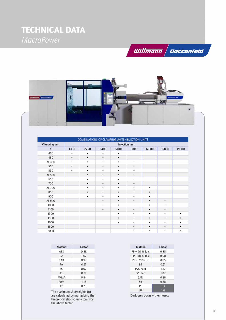
TECHNICAL DATA MacroPower
COMBINATIONS OF CLAMPING UNITS/INJECTION UNITS
Clamping unit Injection unit
t 1330 2250 3400 5100 8800 12800 16800 19000400 • • • •450 • • • •
XL 450 • • • • •500 • • • • •550 • • • • •
XL 550 • • • •650 • • • •700 • • • •
XL 700 • • • • •850 • • • • •900 • • • • •
XL 900 • • • • •1000 • • • • •1100 • • • • •1300 • • • • •1500 • • • • •1600 • • • • •1800 • • • •2000 • • • •
Material Factor
ABS 0.88
CA 1.02
CAB 0.97
PA 0.91
PC 0.97
PE 0.71
PMMA 0.94
POM 1.15
PP 0.73
Material Factor
PP + 20 % Talc 0.85
PP + 40 % Talc 0.98
PP + 20 % GF 0.85
PS 0.91
PVC hard 1.12
PVC soft 1.02
SAN 0.88
SB 0.88
PF 1.3
UP 1.6The maximum shotweights (g) are calculated by multiplying the theoretical shot volume (cm3) by the above factor.
Dark grey boxes = thermosets

14
L
H
DATA MacroPower 400/450
Clamping unit MacroPower 400 MacroPower 450
Clamping force kN 4000 4500
Distance between tie bars mm x mm 900 x 750
Mold height (min.) mm 400
Mold height (max.) mm 850
Opening stroke/opening force mm/kN 1050/162
Maximum daylight mm 1450
Ejector stroke/ejector force mm/kN 250/81
Dry cycle time1) s − mm 2.7 − 525
Injection unit 1330 2250 3400 5100
Screw diameter mm 50 55 65 55 65 75 65 75 85 75 85 95
Screw stroke mm 275 325 375 425
Screw L/D ratio 22 22 22 22
Theoretical shot volume cm3 540 653 913 772 1078 1436 1244 1657 2128 1878 2412 3012
Specific injection pressure bar 2470 2041 1461 2500 2070 1555 2500 2022 1574 2500 2110 1689
Max. screw speed min–1 318 283 222 193
Max. plasticizing rate (PS)2) g/s 48 60 71 53 79 120 62 94 131 82 116 149
Max. screw torque Nm 1940 2373 3759 6048
Nozzle stroke/contact force mm/kN 600/100 850/129 850/129 950/129
Injection rate into air cm3/s 283 343 479 242 338 450 325 433 556 452 581 725
Injection rate into air with twin pump (option) cm3/s 354 429 599 303 423 563 455 606 778 517 663 829
Injection rate into air with hydraulic accumulator (option) cm3/s 567 686 958 726 1014 1351 1040 1385 1779 1291 1659 2072
Barrel heating power kW 21.9 24.2 27 22.7 26.4 32.7 26.4 32.7 37.3 32.7 37.3 41.9
Number of heating zones 5 6 6 6 6 7
Energy efficiency class3)
standard/servo 3/5+ 4/6+ 6/7+ 4/6+ 6/7+ 7/8+ 5/7+ 6/8+ 7/8+ 5/7+ 6/8+ 7/8+
Drive
Drive power kW 45 45 55 75
Oil tank volume l 800 800 800 1100
Electrical power supply without/with Europackage kVA 86/115 88/117 106/135 136/165
Emission sound pressure level4)
standard/servo dB(A) 72/70
Weights, dimensions
Net weight clamping unit kg 12000 12500
Net weight (exclusive oil) injection unit kg 7000 7500 7500 9000
Length x width x height5) m 6.8 x 2.5 x 2.5 6.8 x 2.5 x 2.5 7.1 x 2.5 x 2.5 7.6 x 2.5 x 2.5
Max. mold weight6) kg 6500
Min. mold dimension mm x mm 500 x 500
1) theoretical according to EUROMAP 6 2) according to WITTMANN BATTENFELD norm 3) calculated according to EUROMAP 60.1 (Cycle I) 4) according to ÖNORM EN 201:2010 annex K5) Length with medium screw diameter in rearmost operating position 6) max. 2/3 on clamping platen
W

15
Wei
terg
abe
sow
ie V
ervi
elfä
ltigu
ng d
iese
s D
okum
ente
s, V
erw
ertu
ng u
nd M
ittei
lung
sein
es In
halts
ist v
erbo
ten,
sow
eit n
icht
aus
drüc
klic
h vo
n W
B W
ittm
ann
Gro
up G
mbH
gest
atte
t. Zu
wid
erha
ndlu
ngen
ver
pflic
hten
zu
Scha
dene
rsat
z. A
lle R
echt
e fü
r den
Fal
lde
r Pat
ent-,
Geb
rauc
hsm
uste
r- od
er G
esch
mac
ksm
uste
rein
tragu
ng v
orbe
halte
n.
Id: S
D-A
AB
E82
1 - R
ev. a
.1ja
itner
- 01
.08.
2014
, 01:
16Fo
rmat
A3
Wittmann Batteneld
SCHLIESSSEITE MACRO4000_STDA-2542 Kottingbrunn
Freigegeben Hauptdokument
D14 /4500
09.07.201431.07.2014
Jaitner
1:351 - 1
Jaitner
Teilenummer Version
Dokumentstatus Dokumentverwendung
Blatt Maßstab
Benennung
Geprüft
Erstellt
Zeichnungsnummer
URHEBERSCHUTZ nach ISO 16016
B-BA-A
280
350
420
490
560
280
350
420
490
50,8
203,
2
50,8
203,2
M20-`40(112x)
O33-`(8x)
575
640
1490 5763541116
500900
1289130O
71 -
8163
030
030
0
1470
M16-`32cO50-`40(2x)
500
750
1975
2340
1218 1011
420 420560 560
M20-`40(8x)
1280 1140
350
620
250
160
OH
7
160
OH
7
1470
30
400
850
1450
1050
200
2080
890
1159
3600
35 175
2177 24
77
2438
A
A
B
B
b
210
140
R 35
2092
24M
-`46
140 21
0
16
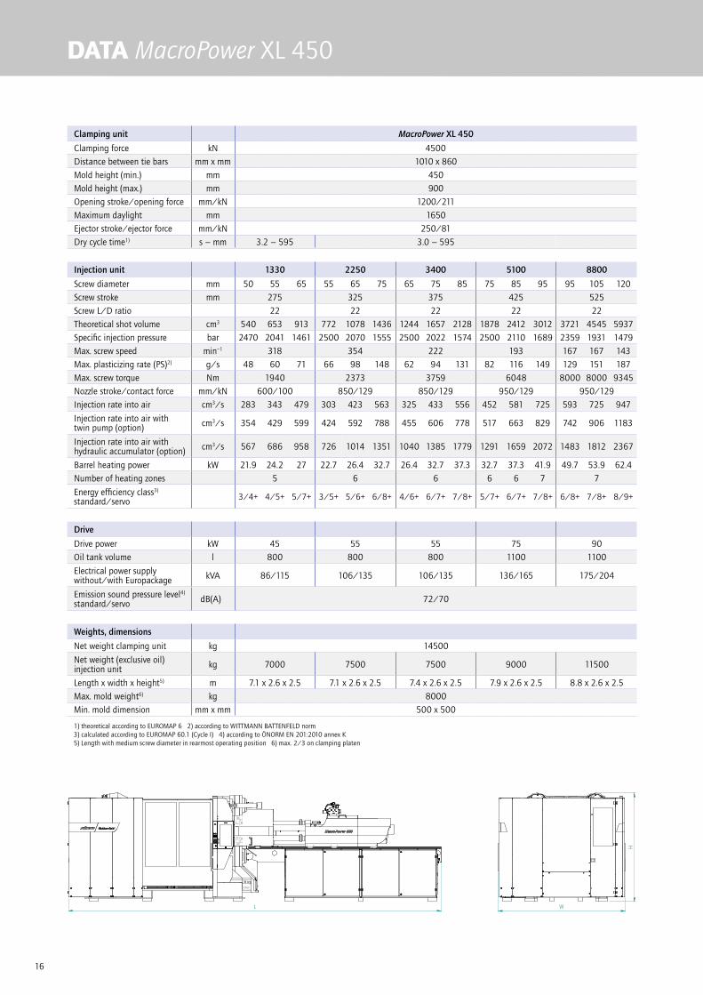
DATA MacroPower XL 450
Clamping unit MacroPower XL 450
Clamping force kN 4500
Distance between tie bars mm x mm 1010 x 860
Mold height (min.) mm 450
Mold height (max.) mm 900
Opening stroke/opening force mm/kN 1200/211
Maximum daylight mm 1650
Ejector stroke/ejector force mm/kN 250/81
Dry cycle time1) s − mm 3.2 − 595 3.0 − 595
Injection unit 1330 2250 3400 5100 8800
Screw diameter mm 50 55 65 55 65 75 65 75 85 75 85 95 95 105 120
Screw stroke mm 275 325 375 425 525
Screw L/D ratio 22 22 22 22 22
Theoretical shot volume cm3 540 653 913 772 1078 1436 1244 1657 2128 1878 2412 3012 3721 4545 5937
Specific injection pressure bar 2470 2041 1461 2500 2070 1555 2500 2022 1574 2500 2110 1689 2359 1931 1479
Max. screw speed min–1 318 354 222 193 167 167 143
Max. plasticizing rate (PS)2) g/s 48 60 71 66 98 148 62 94 131 82 116 149 129 151 187
Max. screw torque Nm 1940 2373 3759 6048 8000 8000 9345
Nozzle stroke/contact force mm/kN 600/100 850/129 850/129 950/129 950/129
Injection rate into air cm3/s 283 343 479 303 423 563 325 433 556 452 581 725 593 725 947
Injection rate into air with twin pump (option) cm3/s 354 429 599 424 592 788 455 606 778 517 663 829 742 906 1183
Injection rate into air with hydraulic accumulator (option) cm3/s 567 686 958 726 1014 1351 1040 1385 1779 1291 1659 2072 1483 1812 2367
Barrel heating power kW 21.9 24.2 27 22.7 26.4 32.7 26.4 32.7 37.3 32.7 37.3 41.9 49.7 53.9 62.4
Number of heating zones 5 6 6 6 6 7 7
Energy efficiency class3)
standard/servo 3/4+ 4/5+ 5/7+ 3/5+ 5/6+ 6/8+ 4/6+ 6/7+ 7/8+ 5/7+ 6/7+ 7/8+ 6/8+ 7/8+ 8/9+
Drive
Drive power kW 45 55 55 75 90
Oil tank volume l 800 800 800 1100 1100
Electrical power supply without/with Europackage kVA 86/115 106/135 106/135 136/165 175/204
Emission sound pressure level4)
standard/servo dB(A) 72/70
Weights, dimensions
Net weight clamping unit kg 14500
Net weight (exclusive oil) injection unit kg 7000 7500 7500 9000 11500
Length x width x height5) m 7.1 x 2.6 x 2.5 7.1 x 2.6 x 2.5 7.4 x 2.6 x 2.5 7.9 x 2.6 x 2.5 8.8 x 2.6 x 2.5
Max. mold weight6) kg 8000
Min. mold dimension mm x mm 500 x 500
1) theoretical according to EUROMAP 6 2) according to WITTMANN BATTENFELD norm 3) calculated according to EUROMAP 60.1 (Cycle I) 4) according to ÖNORM EN 201:2010 annex K5) Length with medium screw diameter in rearmost operating position 6) max. 2/3 on clamping platen
L
H
W

17
Wei
terg
abe
sow
ie V
ervi
elfä
ltigu
ng d
iese
s D
okum
ente
s, V
erw
ertu
ng u
nd M
ittei
lung
sein
es In
halts
ist v
erbo
ten,
sow
eit n
icht
aus
drüc
klic
h vo
n W
B W
ittm
ann
Gro
up G
mbH
gest
atte
t. Zu
wid
erha
ndlu
ngen
ver
pflic
hten
zu
Scha
dene
rsat
z. A
lle R
echt
e fü
r den
Fal
lde
r Pat
ent-,
Geb
rauc
hsm
uste
r- od
er G
esch
mac
ksm
uste
rein
tragu
ng v
orbe
halte
n.
Id: S
D-A
AB
F187
- R
ev. a
.0ja
itner
- 01
.08.
2014
, 01:
17Fo
rmat
A3
Wittmann Batteneld
SCHLIESSSEITE MACROXL4500_STDA-2542 Kottingbrunn
Freigegeben Hauptdokument
D14
22.07.201401.08.2014
Jaitner
1:351 - 1
Jaitner
Teilenummer Version
Dokumentstatus Dokumentverwendung
Blatt Maßstab
Benennung
Geprüft
Erstellt
Zeichnungsnummer
URHEBERSCHUTZ nach ISO 16016
B-BA-A
500
500
50,8
76,2
203,2
355,6
280
350
490
560
63050
,8
76,2
203,
2
355,
6
280
350
420
490
560
M20-`40(132x)O33-`(8x)O53-`(8x)
5761640354
1266
790
500
71 -
81
1470
400
400
2177 24
77
24902588
1010 O 130
1438M16-`32cO50-`40(2x)
826
1288
2145
860
420 420560 560
35 175
M20-`40(8x)450
900
1650
1200
203
24M
-`46
200
H7
O
1470
R 35
30
200
H7
O
295
b1555 1140
645
3875
250
A
A
B
B
1293 1086
420
140
140
1975
2147
555

18
DATA MacroPower 500/550
Clamping unit MacroPower 500 MacroPower 550
Clamping force kN 5000 5500
Distance between tie bars mm x mm 1000 x 850
Mold height (min.) mm 450
Mold height (max.) mm 900
Opening stroke/opening force mm/kN 1200/211
Maximum daylight mm 1650
Ejector stroke/ejector force mm/kN 250/81
Dry cycle time1) s − mm 3.2– 595 3.0 – 595
Injection unit 1330 2250 3400 5100 8800
Screw diameter mm 50 55 65 55 65 75 65 75 85 75 85 95 95 105 120
Screw stroke mm 275 325 375 425 525
Screw L/D ratio 22 22 22 22 22
Theoretical shot volume cm3 540 653 913 772 1078 1436 1244 1657 2128 1878 2412 3012 3721 4545 5937
Specific injection pressure bar 2470 2041 1461 2500 2070 1555 2500 2022 1574 2500 2110 1689 2359 1931 1479
Max. screw speed min–1 318 354 222 193 167 167 143
Max. plasticizing rate (PS)2) g/s 48 60 71 66 98 148 62 94 131 82 116 149 129 151 187
Max. screw torque Nm 1940 2373 3759 6048 8000 8000 9345
Nozzle stroke/contact force mm/kN 600/100 850/129 850/129 950/129 950/129
Injection rate into air cm3/s 283 343 479 303 423 563 325 433 556 452 581 725 593 725 947
Injection rate into air with twin pump (option) cm3/s 368 446 623 424 592 788 455 606 778 517 663 829 742 906 1183
Injection rate into air with hydraulic accumulator (option) cm3/s 567 686 958 726 1014 1351 1040 1385 1779 1291 1659 2072 1483 1812 2367
Barrel heating power kW 21.9 24.2 27 22.7 26.4 32.7 26.4 32.7 37.3 32.7 37.3 41.9 49.7 53.9 62.4
Number of heating zones 5 6 6 6 6 7 7
Energy efficiency class3)
standard/servo 3/4+ 4/5+ 5/7+ 3/5+ 5/6+ 6/8+ 5/6+ 6/7+ 7/8+ 5/7+ 6/7+ 7/8+ 6/8+ 7/8+ 8/9+
Drive
Drive power kW 45 55 55 75 90
Oil tank volume l 800 800 800 1100 1100
Electrical power supply without/with Europackage kVA 78/107 106/135 106/135 136/165 175/204
Emission sound pressure level4)
standard/servo dB(A) 72/70
Weights, dimensions
Net weight clamping unit kg 14500 15000
Net weight (exclusive oil) injection unit kg 7000 7500 7500 9000 11500
Length x width x height5) m 7.1 x 2.6 x 2.5 7.1 x 2.6 x 2.5 7.4 x 2.6 x 2.5 7.9 x 2.6 x 2.5 8.8 x 2.6 x 2.5
Max. mold weight6) kg 8000
Min. mold dimension mm x mm 600 x 600
1) theoretical according to EUROMAP 6 2) according to WITTMANN BATTENFELD norm 3) calculated according to EUROMAP 60.1 (Cycle I) 4) according to ÖNORM EN 201:2010 annex K5) Length with medium screw diameter in rearmost operating position 6) max. 2/3 on clamping platen
L
H
W

19
Wei
terg
abe
sow
ie V
ervi
elfä
ltigu
ng d
iese
s D
okum
ente
s, V
erw
ertu
ng u
nd M
ittei
lung
sein
es In
halts
ist v
erbo
ten,
sow
eit n
icht
aus
drüc
klic
h vo
n W
B W
ittm
ann
Gro
up G
mbH
gest
atte
t. Zu
wid
erha
ndlu
ngen
ver
pflic
hten
zu
Scha
dene
rsat
z. A
lle R
echt
e fü
r den
Fal
lde
r Pat
ent-,
Geb
rauc
hsm
uste
r- od
er G
esch
mac
ksm
uste
rein
tragu
ng v
orbe
halte
n.
Id: S
D-A
AB
E82
0 - R
ev. a
.1ja
itner
- 01
.08.
2014
, 01:
16Fo
rmat
A3
Wittmann Batteneld
SCHLIESSSEITE MACRO5000_STDA-2542 Kottingbrunn
Freigegeben Hauptdokument
D14 /5500
09.07.201401.08.2014
Jaitner
1:351 - 1
Jaitner
Teilenummer Version
Dokumentstatus Dokumentverwendung
Blatt Maßstab
Benennung
Geprüft
Erstellt
Zeichnungsnummer
URHEBERSCHUTZ nach ISO 16016
B-BA-A
600
600
50,8
76,2
203,2
355,6
280
350
490
560
630
50,8
76,2
203,
2
355,
6
280
350
420
490
560
M20-`40(132x)O33-`(8x)O53-`(8x)
5761640354
1266
790
500
71 -
81
1470
400
400
2177 24
77
24902588
1000 O 140
1438M16-`32cO50-`40(2x)
826
1288
2145
850
420 420560 560
35 175
M20-`40(8x)450
900
1650
1200
325
24M
-`46
200
H7
O
1470
R 35
30
200
H7
O
295
b1555 1140
645
3875
250
A
A
B
B
1293 1086
420
140
140
1975
2163
555

20
DATA MacroPower XL 550
Clamping unit MacroPower XL 550
Clamping force kN 5500
Distance between tie bars mm x mm 1120 x 970
Mold height (min.) mm 450
Mold height (max.) mm 950
Opening stroke/opening force mm/kN 1400/211
Maximum daylight mm 1850
Ejector stroke/ejector force mm/kN 250/81
Dry cycle time1) s − mm 3.3 – 665
Injection unit 2250 3400 5100 8800
Screw diameter mm 55 65 75 65 75 85 75 85 95 95 105 120
Screw stroke mm 325 375 425 525
Screw L/D ratio 22 22 22 22
Theoretical shot volume cm3 772 1078 1436 1244 1657 2128 1878 2412 3012 3721 4545 5937
Specific injection pressure bar 2500 2070 1555 2500 2022 1574 2500 2110 1689 2359 1931 1479
Max. screw speed min–1 354 222 193 167 167 143
Max. plasticizing rate (PS)2) g/s 66 98 148 62 94 131 82 116 149 129 151 187
Max. screw torque Nm 2373 3759 6048 8000 8000 9345
Nozzle stroke/contact force mm/kN 850/129 850/129 950/129 950/129
Injection rate into air cm3/s 303 423 563 325 433 556 452 581 725 593 725 947
Injection rate into air with twin pump (option) cm3/s 424 592 788 455 606 778 517 663 829 742 906 1183
Injection rate into air with hydraulic accumulator (option) cm3/s 726 1014 1351 1040 1385 1779 1291 1659 2072 1483 1812 2367
Barrel heating power kW 22.7 26.4 32.7 26.4 32.7 37.3 32.7 37.3 41.9 49.7 53.9 62.4
Number of heating zones 6 6 6 6 7 7
Energy efficiency class3)
standard/servo 3/5+ 5/6+ 6/8+ 4/6+ 6/7+ 7/8+ 5/7+ 6/7+ 7/8+ 6/8+ 7/8+ 8/9+
Drive
Drive power kW 55 55 75 90
Oil tank volume l 800 800 1100 1100
Electrical power supply without/with Europackage kVA 106/135 106/135 136/165 175/204
Emission sound pressure level4)
standard/servo dB(A) 72/70
Weights, dimensions
Net weight clamping unit kg 19500
Net weight (exclusive oil) injection unit kg 7500 7500 9000 11500
Length x width x height5) m 7.4 x 2.8 x 2.5 7.7 x 2.8 x 2.5 8.2 x 2.8 x 2.5 9.1 x 2.8 x 2.5
Max. mold weight6) kg 10000
Min. mold dimension mm x mm 550 x 550
1) theoretical according to EUROMAP 6 2) according to WITTMANN BATTENFELD norm 3) calculated according to EUROMAP 60.1 (Cycle I) 4) according to ÖNORM EN 201:2010 annex K5) Length with medium screw diameter in rearmost operating position 6) max. 2/3 on clamping platen
L
H
W
21
Wei
terg
abe
sow
ie V
ervi
elfä
ltigu
ng d
iese
s D
okum
ente
s, V
erw
ertu
ng u
nd M
ittei
lung
sein
es In
halts
ist v
erbo
ten,
sow
eit n
icht
aus
drüc
klic
h vo
n W
B W
ittm
ann
Gro
up G
mbH
gest
atte
t. Zu
wid
erha
ndlu
ngen
ver
pflic
hten
zu
Scha
dene
rsat
z. A
lle R
echt
e fü
r den
Fal
lde
r Pat
ent-,
Geb
rauc
hsm
uste
r- od
er G
esch
mac
ksm
uste
rein
tragu
ng v
orbe
halte
n.
Id: S
D-A
AB
F184
- R
ev. a
.0ja
itner
- 01
.08.
2014
, 01:
29Fo
rmat
A3
Wittmann Batteneld
SCHLIESSSEITE MACROXL5500_STDA-2542 Kottingbrunn
Freigegeben Hauptdokument
D14
22.07.201401.08.2014
Jaitner
1:351 - 1
Jaitner
Teilenummer Version
Dokumentstatus Dokumentverwendung
Blatt Maßstab
Benennung
Geprüft
Erstellt
Zeichnungsnummer
URHEBERSCHUTZ nach ISO 16016
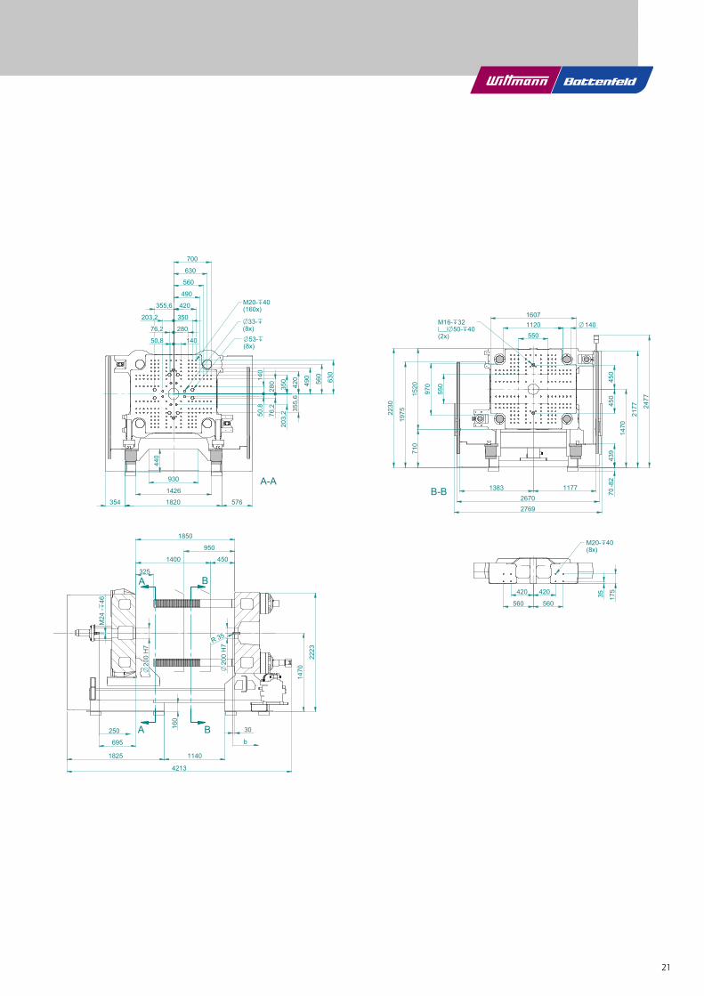
A-A
550280
350
420
490
560
630
700
355,6
280
350
420
490
560
630
355,
6
O53-`(8x)
O33-`(8x)
M20-`40(160x)
203,2
440
930
1426
354 1820 576B-B
11201607
140OM16-`32cO50-`40(2x)
450
450
70-8
243
9
1470
2177 24
77
550
970
710
1520
11771383
2769
420
560
420
56035 17
5
M20-`40(8x)
325
450
950
1850
1400
M24
-`46
200
H7
O
200
H7
O
1470
30
1825 1140
4213
160
b
A
A
2670
B
B
2230
140
695
250
140
203,
250,8
76,2
76,2
50,8
R 35
1975
2223
22
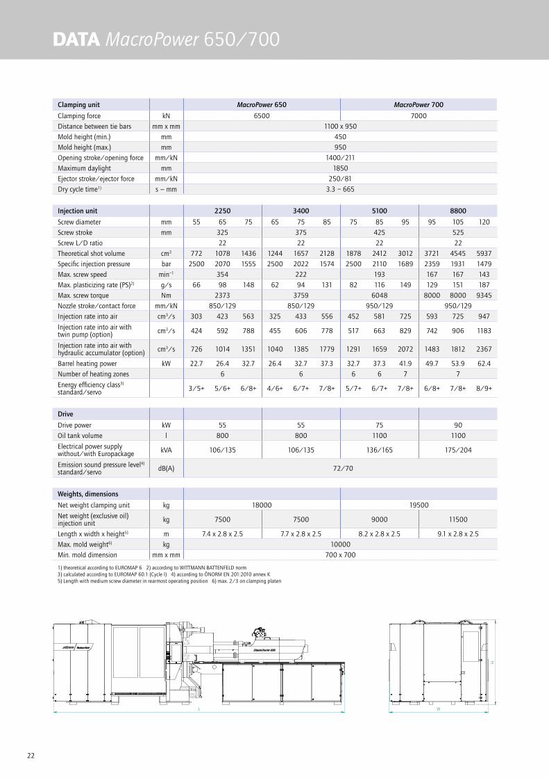
DATA MacroPower 650/700
Clamping unit MacroPower 650 MacroPower 700
Clamping force kN 6500 7000
Distance between tie bars mm x mm 1100 x 950
Mold height (min.) mm 450
Mold height (max.) mm 950
Opening stroke/opening force mm/kN 1400/211
Maximum daylight mm 1850
Ejector stroke/ejector force mm/kN 250/81
Dry cycle time1) s − mm 3.3 – 665
Injection unit 2250 3400 5100 8800
Screw diameter mm 55 65 75 65 75 85 75 85 95 95 105 120
Screw stroke mm 325 375 425 525
Screw L/D ratio 22 22 22 22
Theoretical shot volume cm3 772 1078 1436 1244 1657 2128 1878 2412 3012 3721 4545 5937
Specific injection pressure bar 2500 2070 1555 2500 2022 1574 2500 2110 1689 2359 1931 1479
Max. screw speed min–1 354 222 193 167 167 143
Max. plasticizing rate (PS)2) g/s 66 98 148 62 94 131 82 116 149 129 151 187
Max. screw torque Nm 2373 3759 6048 8000 8000 9345
Nozzle stroke/contact force mm/kN 850/129 850/129 950/129 950/129
Injection rate into air cm3/s 303 423 563 325 433 556 452 581 725 593 725 947
Injection rate into air with twin pump (option) cm3/s 424 592 788 455 606 778 517 663 829 742 906 1183
Injection rate into air with hydraulic accumulator (option) cm3/s 726 1014 1351 1040 1385 1779 1291 1659 2072 1483 1812 2367
Barrel heating power kW 22.7 26.4 32.7 26.4 32.7 37.3 32.7 37.3 41.9 49.7 53.9 62.4
Number of heating zones 6 6 6 6 7 7
Energy efficiency class3)
standard/servo 3/5+ 5/6+ 6/8+ 4/6+ 6/7+ 7/8+ 5/7+ 6/7+ 7/8+ 6/8+ 7/8+ 8/9+
Drive
Drive power kW 55 55 75 90
Oil tank volume l 800 800 1100 1100
Electrical power supply without/with Europackage kVA 106/135 106/135 136/165 175/204
Emission sound pressure level4)
standard/servo dB(A) 72/70
Weights, dimensions
Net weight clamping unit kg 18000 19500
Net weight (exclusive oil) injection unit kg 7500 7500 9000 11500
Length x width x height5) m 7.4 x 2.8 x 2.5 7.7 x 2.8 x 2.5 8.2 x 2.8 x 2.5 9.1 x 2.8 x 2.5
Max. mold weight6) kg 10000
Min. mold dimension mm x mm 700 x 700
1) theoretical according to EUROMAP 6 2) according to WITTMANN BATTENFELD norm 3) calculated according to EUROMAP 60.1 (Cycle I) 4) according to ÖNORM EN 201:2010 annex K5) Length with medium screw diameter in rearmost operating position 6) max. 2/3 on clamping platen
L
H
W

23
Wei
terg
abe
sow
ie V
ervi
elfä
ltigu
ng d
iese
s D
okum
ente
s, V
erw
ertu
ng u
nd M
ittei
lung
sein
es In
halts
ist v
erbo
ten,
sow
eit n
icht
aus
drüc
klic
h vo
n W
B W
ittm
ann
Gro
up G
mbH
gest
atte
t. Zu
wid
erha
ndlu
ngen
ver
pflic
hten
zu
Scha
dene
rsat
z. A
lle R
echt
e fü
r den
Fal
lde
r Pat
ent-,
Geb
rauc
hsm
uste
r- od
er G
esch
mac
ksm
uste
rein
tragu
ng v
orbe
halte
n.
Id: S
D-A
AB
E79
1 - R
ev. a
.2ja
itner
- 01
.08.
2014
, 01:
19Fo
rmat
A3
Wittmann Batteneld
SCHLIESSSEITE MACRO6500_STDA-2542 Kottingbrunn
Freigegeben Hauptdokument
D14 /7000
09.07.201401.08.2014
Jaitner
1:351 - 1
Jaitner
Teilenummer Version
Dokumentstatus Dokumentverwendung
Blatt Maßstab
Benennung
Geprüft
Erstellt
Zeichnungsnummer
URHEBERSCHUTZ nach ISO 16016
A-A
700280
350
420
490
560
630
700
355,6
280
350
420
490
560
630
355,
6
O53-`(8x)
O33-`(8x)
M20-`40(160x)
203,2
440
930
1426
354 1820 576
B-B
11001607
160OM16-`32cO50-`40(2x)
450
450
70-8
243
9
1470
2177 24
77
700
950
710
1520
11771383
2769
420
560
420
56035 17
5
M20-`40(8x)
485
450
950
1850
1400
M24
-`46
200
H7
O
200
H7
O
1470
30
1825 1140
4213
160
b
A
A
2670
B
B
2230
140
695
250
140
203,
250,8
76,2
76,2
50,8
R 35
1975
2252
24
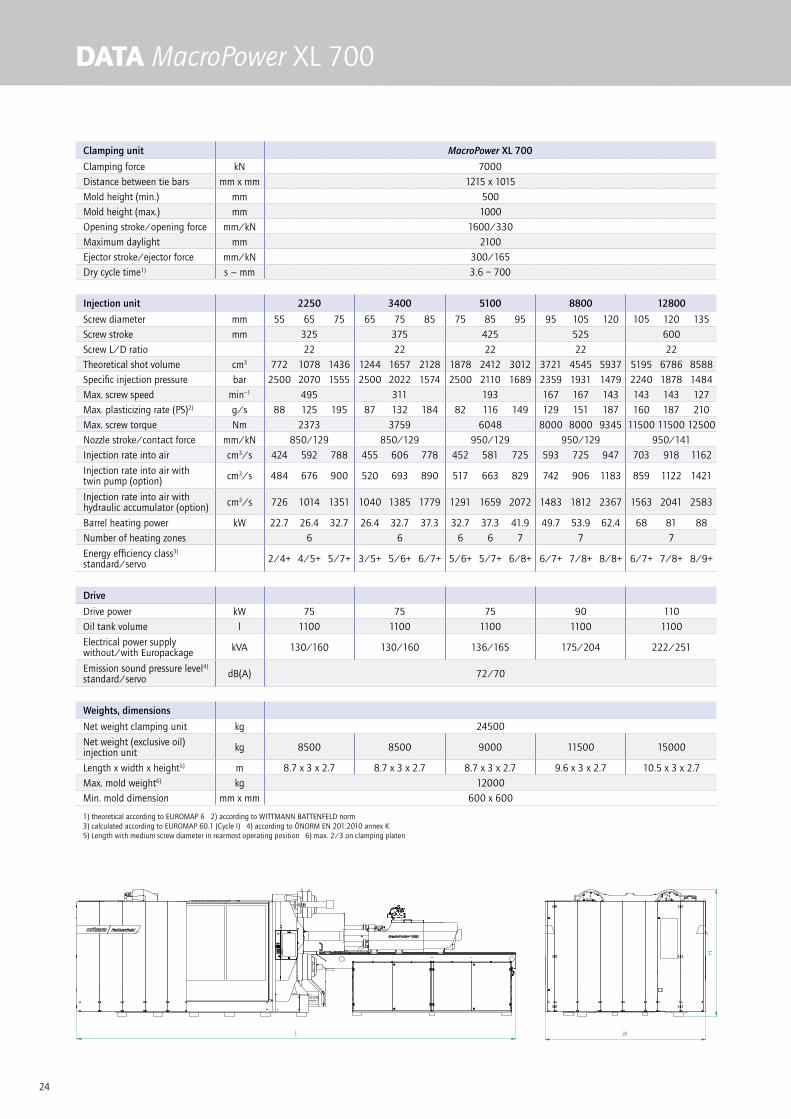
DATA MacroPower XL 700
Clamping unit MacroPower XL 700
Clamping force kN 7000
Distance between tie bars mm x mm 1215 x 1015
Mold height (min.) mm 500
Mold height (max.) mm 1000
Opening stroke/opening force mm/kN 1600/330
Maximum daylight mm 2100
Ejector stroke/ejector force mm/kN 300/165
Dry cycle time1) s − mm 3.6 – 700
Injection unit 2250 3400 5100 8800 12800
Screw diameter mm 55 65 75 65 75 85 75 85 95 95 105 120 105 120 135
Screw stroke mm 325 375 425 525 600
Screw L/D ratio 22 22 22 22 22
Theoretical shot volume cm3 772 1078 1436 1244 1657 2128 1878 2412 3012 3721 4545 5937 5195 6786 8588
Specific injection pressure bar 2500 2070 1555 2500 2022 1574 2500 2110 1689 2359 1931 1479 2240 1878 1484
Max. screw speed min–1 495 311 193 167 167 143 143 143 127
Max. plasticizing rate (PS)2) g/s 88 125 195 87 132 184 82 116 149 129 151 187 160 187 210
Max. screw torque Nm 2373 3759 6048 8000 8000 9345 11500 11500 12500
Nozzle stroke/contact force mm/kN 850/129 850/129 950/129 950/129 950/141
Injection rate into air cm3/s 424 592 788 455 606 778 452 581 725 593 725 947 703 918 1162
Injection rate into air with twin pump (option) cm3/s 484 676 900 520 693 890 517 663 829 742 906 1183 859 1122 1421
Injection rate into air with hydraulic accumulator (option) cm3/s 726 1014 1351 1040 1385 1779 1291 1659 2072 1483 1812 2367 1563 2041 2583
Barrel heating power kW 22.7 26.4 32.7 26.4 32.7 37.3 32.7 37.3 41.9 49.7 53.9 62.4 68 81 88
Number of heating zones 6 6 6 6 7 7 7
Energy efficiency class3)
standard/servo 2/4+ 4/5+ 5/7+ 3/5+ 5/6+ 6/7+ 5/6+ 5/7+ 6/8+ 6/7+ 7/8+ 8/8+ 6/7+ 7/8+ 8/9+
Drive
Drive power kW 75 75 75 90 110
Oil tank volume l 1100 1100 1100 1100 1100
Electrical power supply without/with Europackage kVA 130/160 130/160 136/165 175/204 222/251
Emission sound pressure level4)
standard/servo dB(A) 72/70
Weights, dimensions
Net weight clamping unit kg 24500
Net weight (exclusive oil) injection unit kg 8500 8500 9000 11500 15000
Length x width x height5) m 8.7 x 3 x 2.7 8.7 x 3 x 2.7 8.7 x 3 x 2.7 9.6 x 3 x 2.7 10.5 x 3 x 2.7
Max. mold weight6) kg 12000
Min. mold dimension mm x mm 600 x 600
1) theoretical according to EUROMAP 6 2) according to WITTMANN BATTENFELD norm 3) calculated according to EUROMAP 60.1 (Cycle I) 4) according to ÖNORM EN 201:2010 annex K5) Length with medium screw diameter in rearmost operating position 6) max. 2/3 on clamping platen
L W
H

25
Wei
terg
abe
sow
ie V
ervi
elfä
ltigu
ng d
iese
s D
okum
ente
s, V
erw
ertu
ng u
nd M
ittei
lung
sein
es In
halts
ist v
erbo
ten,
sow
eit n
icht
aus
drüc
klic
h vo
n W
B W
ittm
ann
Gro
up G
mbH
gest
atte
t. Zu
wid
erha
ndlu
ngen
ver
pflic
hten
zu
Scha
dene
rsat
z. A
lle R
echt
e fü
r den
Fal
lde
r Pat
ent-,
Geb
rauc
hsm
uste
r- od
er G
esch
mac
ksm
uste
rein
tragu
ng v
orbe
halte
n.
Id: S
D-A
AB
F183
- R
ev. a
.1ja
itner
- 05
.08.
2014
, 08:
46Fo
rmat
A3
Wittmann Batteneld
SCHLIESSSEITE MACROXL7000_STDA-2542 Kottingbrunn
Freigegeben Hauptdokument
D14
22.07.201404.08.2014
Jaitner
1:351 - 1
Jaitner
Teilenummer Version
Dokumentstatus Dokumentverwendung
Blatt Maßstab
Benennung
Geprüft
Erstellt
Zeichnungsnummer
URHEBERSCHUTZ nach ISO 16016
A-A
600
600
B-B
280
420
560
700
50,8
76,2
203,2
355,6 M24-`48(84x)O33-`(8x)O53-`(8x)
420 56
0 700
50,8
76,2
203,
2
355,
6
370
2009
1215
1015
1720
500
50015
5069
5
1470
70-8
2
M16-`32cO50-`40(2x)
573
500
830300
4962
30
1470
24M
-`48
M24-`48(12x)
280
2909
O 160
2327 26
27
420
630
420
63070 175
280
380
1500 1300
3009
2245
2180
b
A
A
B
B
140
250
H7
O
250
H7
O
R 35
140
2284
1000
2100
1600
1211390 590

26
DATA MacroPower 850/900
Clamping unit MacroPower 850 MacroPower 900
Clamping force kN 8500 9000
Distance between tie bars mm x mm 1200 x 1000
Mold height (min.) mm 500
Mold height (max.) mm 1000
Opening stroke/opening force mm/kN 1600/330
Maximum daylight mm 2100
Ejector stroke/ejector force mm/kN 300/165
Dry cycle time1) s − mm 3.6 – 700
Injection unit 2250 3400 5100 8800 12800
Screw diameter mm 55 65 75 65 75 85 75 85 95 95 105 120 105 120 135
Screw stroke mm 325 375 425 525 600
Screw L/D ratio 22 22 22 22 22
Theoretical shot volume cm3 772 1078 1436 1244 1657 2128 1878 2412 3012 3721 4545 5937 5195 6786 8588
Specific injection pressure bar 2500 2070 1555 2500 2022 1574 2500 2110 1689 2359 1931 1479 2240 1878 1484
Max. screw speed min–1 495 311 193 167 167 143 143 143 127
Max. plasticizing rate (PS)2) g/s 88 125 195 87 132 184 82 116 149 129 151 187 160 187 210
Max. screw torque Nm 2373 3759 6048 8000 8000 9345 11500 11500 12500
Nozzle stroke/contact force mm/kN 850/129 850/129 950/129 950/129 950/141
Injection rate into air cm3/s 424 592 788 455 606 778 452 581 725 593 725 947 703 918 1162
Injection rate into air with twin pump (option) cm3/s 484 676 900 520 693 890 517 663 829 742 906 1183 859 1122 1421
Injection rate into air with hydraulic accumulator (option) cm3/s 726 1014 1351 1040 1385 1779 1291 1659 2072 1483 1812 2367 1563 2041 2583
Barrel heating power kW 22.7 26.4 32.7 26.4 32.7 37.3 32.7 37.3 41.9 49.7 53.9 62.4 68 81 88
Number of heating zones 6 6 6 6 7 7 7
Energy efficiency class3)
standard/servo 2/4+ 3/5+ 5/7+ 3/5+ 5/6+ 6/7+ 4/6+ 5/7+ 6/8+ 6/7+ 7/8+ 8/8+ 6/7+ 7/8+ 8/9+
Drive
Drive power kW 75 75 75 90 110
Oil tank volume l 1100 1100 1100 1100 1100
Electrical power supply without/with Europackage kVA 130/160 130/160 136/165 175/204 222/251
Emission sound pressure level4)
standard/servo dB(A) 72/70
Weights, dimensions
Net weight clamping unit kg 24500 26500
Net weight (exclusive oil) injection unit kg 8500 8500 9000 11500 15000
Length x width x height5) m 8.7 x 3 x 2.7 8.7 x 3 x 2.7 8.7 x 3 x 2.7 9.6 x 3 x 2.7 10.5 x 3 x 2.7
Max. mold weight6) kg 12000
Min. mold dimension mm x mm 800 x 800
1) theoretical according to EUROMAP 6 2) according to WITTMANN BATTENFELD norm 3) calculated according to EUROMAP 60.1 (Cycle I) 4) according to ÖNORM EN 201:2010 annex K5) Length with medium screw diameter in rearmost operating position 6) max. 2/3 on clamping platen
L W
H

27
Wei
terg
abe
sow
ie V
ervi
elfä
ltigu
ng d
iese
s D
okum
ente
s, V
erw
ertu
ng u
nd M
ittei
lung
sein
es In
halts
ist v
erbo
ten,
sow
eit n
icht
aus
drüc
klic
h vo
n W
B W
ittm
ann
Gro
up G
mbH
gest
atte
t. Zu
wid
erha
ndlu
ngen
ver
pflic
hten
zu
Scha
dene
rsat
z. A
lle R
echt
e fü
r den
Fal
lde
r Pat
ent-,
Geb
rauc
hsm
uste
r- od
er G
esch
mac
ksm
uste
rein
tragu
ng v
orbe
halte
n.
Id: S
D-A
AB
E82
9 - R
ev. a
.2ja
itner
- 05
.08.
2014
, 08:
13Fo
rmat
A3
Wittmann Batteneld
SCHLIESSSEITE MACRO8500_STDA-2542 Kottingbrunn
Freigegeben Hauptdokument
D14 /9000
10.07.201404.08.2014
Jaitner
1:351 - 1
Jaitner
Teilenummer Version
Dokumentstatus Dokumentverwendung
Blatt Maßstab
Benennung
Geprüft
Erstellt
Zeichnungsnummer
URHEBERSCHUTZ nach ISO 16016
A-A
800
800
B-B
280
420
560
700
50,8
76,2
203,2
355,6 M24-`48(84x)O33-`(8x)O53-`(8x)
420 56
0 700
50,8
76,2
203,
2
355,
6
370
2009
1200
1000
1720
50015
5069
5
1470
70-8
2
M16-`32cO50-`40(2x)
645
500
830300
4962
30
1470
24M
-`48
M24-`48(12x)
280
2909
O 175
2327 26
27
420
630
420
630
70 175
280
380
1500 1300
3009
2245
2180
b
A
A
B
B
140
250
H7
O
250
H7
O
R 35
140
2302
1000
2100
1600
500
1211590390

28
DATA MacroPower XL 900
Clamping unit MacroPower XL 900
Clamping force kN 9000
Distance between tie bars mm x mm 1475 x 1125
Mold height (min.) mm 600
Mold height (max.) mm 1200
Opening stroke/opening force mm/kN 1800/330
Maximum daylight mm 2400
Ejector stroke/ejector force mm/kN 300/165
Dry cycle time1) s − mm 4.0 – 770
Injection unit 3400 5100 8800 12800 16800
Screw diameter mm 65 75 85 75 85 95 95 105 120 105 120 135 120 135 150
Screw stroke mm 375 425 525 600 675
Screw L/D ratio 22 22 22 22 22
Theoretical shot volume cm3 1244 1657 2128 1878 2412 3012 3721 4545 5937 5195 6786 8588 7634 9662 11928
Specific injection pressure bar 2500 2022 1574 2500 2110 1689 2359 1931 1479 2240 1878 1484 2203 1741 1410
Max. screw speed min–1 311 221 167 167 143 143 143 127 125
Max. plasticizing rate (PS)2) g/s 87 132 184 94 133 171 129 151 187 160 187 210 170 210 260
Max. screw torque Nm 3759 6048 8000 8000 9345 11500 11500 12500 15750
Nozzle stroke/contact force mm/kN 850/129 950/129 950/129 950/141 1000/200
Injection rate into air cm3/s 455 606 778 517 663 829 593 725 947 703 918 1162 936 1185 1463
Injection rate into air with twin pump (option) cm3/s 520 693 890 646 829 1036 742 906 1183 859 1122 1421 1106 1400 1729
Injection rate into air with hydraulic accumulator (option) cm3/s 1040 1385 1779 1291 1659 2072 1483 1812 2367 1563 2041 2583 1702 2154 2660
Barrel heating power kW 26.4 32.7 37.3 32.7 37.3 41.9 49.7 53.9 62.4 68 81 88 87 100 110
Number of heating zones 6 6 6 7 7 7 7
Energy efficiency class3)
standard/servo 3/5+ 5/6+ 6/7+ 4/6+ 5/7+ 6/7+ 6/7+ 7/8+ 8/8+ 6/7+ 7/8+ 8/9+ 7/8+ 7/8+ 8/9+
Drive
Drive power kW 75 90 90 110 90 + 45
Oil tank volume l 1100 1100 1100 1100 1600
Electrical power supply without/with Europackage kVA 130/160 158/188 179/209 222/251 269/299
Emission sound pressure level4)
standard/servo dB(A) 72/70 74/72
Weights, dimensions
Net weight clamping unit kg 37000
Net weight (exclusive oil) injection unit kg 9000 9500 11500 15000 20000
Length x width x height5) m 9.2 x 3.4 x 2.7 9.2 x 3.4 x 2.7 10.1 x 3.4 x 2.7 11 x 3.4 x 2.7 11.7 x 3.4 x 2.7
Max. mold weight6) kg 19000
Min. mold dimension mm x mm 800 x 700
1) theoretical according to EUROMAP 6 2) according to WITTMANN BATTENFELD norm 3) calculated according to EUROMAP 60.1 (Cycle I) 4) according to ÖNORM EN 201:2010 annex K5) Length with medium screw diameter in rearmost operating position 6) max. 2/3 on clamping platen
L W
H

29
Wei
terg
abe
sow
ie V
ervi
elfä
ltigu
ng d
iese
s D
okum
ente
s, V
erw
ertu
ng u
nd M
ittei
lung
sein
es In
halts
ist v
erbo
ten,
sow
eit n
icht
aus
drüc
klic
h vo
n W
B W
ittm
ann
Gro
up G
mbH
gest
atte
t. Zu
wid
erha
ndlu
ngen
ver
pflic
hten
zu
Scha
dene
rsat
z. A
lle R
echt
e fü
r den
Fal
lde
r Pat
ent-,
Geb
rauc
hsm
uste
r- od
er G
esch
mac
ksm
uste
rein
tragu
ng v
orbe
halte
n.
Id: S
D-A
AB
E85
5 - R
ev. a
.2ja
itner
- 03
.09.
2014
, 01:
05Fo
rmat
A3
Wittmann Batteneld
SCHLIESSSEITE MACROXL9000_STDA-2542 Kottingbrunn
Freigegeben Hauptdokument
D14
10.07.201405.08.2014
Jaitner
1:351 - 1
Jaitner
Teilenummer Version
Dokumentstatus Dokumentverwendung
Blatt Maßstab
Benennung
Geprüft
Erstellt
Zeichnungsnummer
URHEBERSCHUTZ nach ISO 16016
A-A
800
B-B
420
560
700
840
280
355,6
508
127
76,2
420 56
0 700
355,
6
508
2364
O53-`(16x)
M24-`48(88x)
500
1477
700
745
70-8
2
M24-`48(12x)
250
H7
O
250
H7
O
1800
300905
5360
30
1610
M16-`33cO50-`40(2x)
370
560
840
560
840
642
1475 175O
2002
1125
1730
1677
3364
380
1610
2327 26
27
70
210 35
0
3264
2475
b
B
B
A
A
600
1200
2400
R 35
2177
140
280
76,2
127
2504
24M
-`48
140
500
1466590390
30
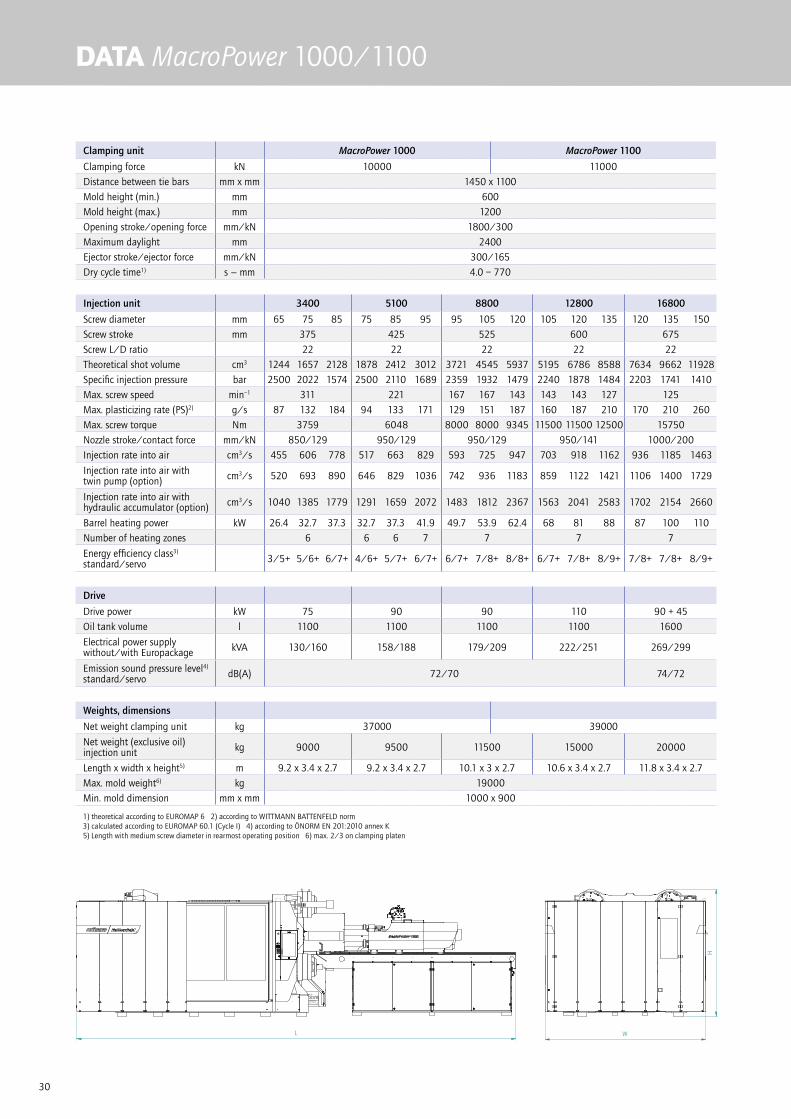
DATA MacroPower 1000/1100
Clamping unit MacroPower 1000 MacroPower 1100
Clamping force kN 10000 11000
Distance between tie bars mm x mm 1450 x 1100
Mold height (min.) mm 600
Mold height (max.) mm 1200
Opening stroke/opening force mm/kN 1800/300
Maximum daylight mm 2400
Ejector stroke/ejector force mm/kN 300/165
Dry cycle time1) s − mm 4.0 – 770
Injection unit 3400 5100 8800 12800 16800
Screw diameter mm 65 75 85 75 85 95 95 105 120 105 120 135 120 135 150
Screw stroke mm 375 425 525 600 675
Screw L/D ratio 22 22 22 22 22
Theoretical shot volume cm3 1244 1657 2128 1878 2412 3012 3721 4545 5937 5195 6786 8588 7634 9662 11928
Specific injection pressure bar 2500 2022 1574 2500 2110 1689 2359 1932 1479 2240 1878 1484 2203 1741 1410
Max. screw speed min–1 311 221 167 167 143 143 143 127 125
Max. plasticizing rate (PS)2) g/s 87 132 184 94 133 171 129 151 187 160 187 210 170 210 260
Max. screw torque Nm 3759 6048 8000 8000 9345 11500 11500 12500 15750
Nozzle stroke/contact force mm/kN 850/129 950/129 950/129 950/141 1000/200
Injection rate into air cm3/s 455 606 778 517 663 829 593 725 947 703 918 1162 936 1185 1463
Injection rate into air with twin pump (option) cm3/s 520 693 890 646 829 1036 742 936 1183 859 1122 1421 1106 1400 1729
Injection rate into air with hydraulic accumulator (option) cm3/s 1040 1385 1779 1291 1659 2072 1483 1812 2367 1563 2041 2583 1702 2154 2660
Barrel heating power kW 26.4 32.7 37.3 32.7 37.3 41.9 49.7 53.9 62.4 68 81 88 87 100 110
Number of heating zones 6 6 6 7 7 7 7
Energy efficiency class3)
standard/servo 3/5+ 5/6+ 6/7+ 4/6+ 5/7+ 6/7+ 6/7+ 7/8+ 8/8+ 6/7+ 7/8+ 8/9+ 7/8+ 7/8+ 8/9+
Drive
Drive power kW 75 90 90 110 90 + 45
Oil tank volume l 1100 1100 1100 1100 1600
Electrical power supply without/with Europackage kVA 130/160 158/188 179/209 222/251 269/299
Emission sound pressure level4)
standard/servo dB(A) 72/70 74/72
Weights, dimensions
Net weight clamping unit kg 37000 39000
Net weight (exclusive oil) injection unit kg 9000 9500 11500 15000 20000
Length x width x height5) m 9.2 x 3.4 x 2.7 9.2 x 3.4 x 2.7 10.1 x 3 x 2.7 10.6 x 3.4 x 2.7 11.8 x 3.4 x 2.7
Max. mold weight6) kg 19000
Min. mold dimension mm x mm 1000 x 900
1) theoretical according to EUROMAP 6 2) according to WITTMANN BATTENFELD norm 3) calculated according to EUROMAP 60.1 (Cycle I) 4) according to ÖNORM EN 201:2010 annex K5) Length with medium screw diameter in rearmost operating position 6) max. 2/3 on clamping platen
L W
H

31
Wei
terg
abe
sow
ie V
ervi
elfä
ltigu
ng d
iese
s D
okum
ente
s, V
erw
ertu
ng u
nd M
ittei
lung
sein
es In
halts
ist v
erbo
ten,
sow
eit n
icht
aus
drüc
klic
h vo
n W
B W
ittm
ann
Gro
up G
mbH
gest
atte
t. Zu
wid
erha
ndlu
ngen
ver
pflic
hten
zu
Scha
dene
rsat
z. A
lle R
echt
e fü
r den
Fal
lde
r Pat
ent-,
Geb
rauc
hsm
uste
r- od
er G
esch
mac
ksm
uste
rein
tragu
ng v
orbe
halte
n.
Id: S
D-A
AB
E78
3 - R
ev. a
.2ja
itner
- 05
.08.
2014
, 08:
17Fo
rmat
A3
Wittmann Batteneld
SCHLIESSSEITE MACRO10000_STDA-2542 Kottingbrunn
Freigegeben Hauptdokument
D14 /11000
09.07.201404.08.2014
Jaitner
1:351 - 1
Jaitner
Teilenummer Version
Dokumentstatus Dokumentverwendung
Blatt Maßstab
Benennung
Geprüft
Erstellt
Zeichnungsnummer
URHEBERSCHUTZ nach ISO 16016
A-A
1000
B-B
420
560
700
840
280
355,6
508
127
76,2
420 56
0 700
355,
6
508
2364
O53-`(16x)
M24-`48(88x)
500
1477
900
745
70-8
2
M24-`48(12x)
250
H7
O
250
H7
O
1800
24M
-`48
300905
5360
30
1610
M16-`32cO50-`40(2x)
370
560
840
560
840
650
1450 200O
2002
1100
1730
1677
3364
380
1610
2327 26
27
70
210 35
0
3264
2475
b
B
B
A
A
600
1200
2400
R 35
2177
140
140 28
0
76,2
127
2539
500
1466590390

32
DATA MacroPower 1300/1500
Clamping unit MacroPower 1300 MacroPower 1500
Clamping force kN 13000 15000
Distance between tie bars mm x mm 1600 x 1250
Mold height (min.) mm 700
Mold height (max.) mm 1400
Opening stroke/opening force mm/kN 2200/475 2400/475
Maximum daylight mm 2900 3100
Ejector stroke/ejector force mm/kN 300/200
Dry cycle time1) s − mm 4.5 – 875 4.3 – 875
Injection unit 5100 8800 12800 16800 19000
Screw diameter mm 75 85 95 95 105 120 105 120 135 120 135 150 135 150 165
Screw stroke mm 425 525 600 675 675
Screw L/D ratio 22 22 22 22 22
Theoretical shot volume cm3 1878 2412 3012 3721 4545 5937 5195 6786 8588 7634 9662 11928 9662 11928 14433
Specific injection pressure bar 2500 2110 1689 2359 1931 1479 2240 1878 1484 2203 1741 1410 1934 1567 1295
Max. screw speed min–1 221 167 167 143 143 143 127 125 125 125 97
Max. plasticizing rate (PS)2) g/s 94 133 171 129 151 187 160 187 210 170 210 260 210 260 260
Max. screw torque Nm 6048 8000 8000 9345 11500 11500 12500 15750 17500 17500 22500
Nozzle stroke/contact force mm/kN 950/129 950/129 950/141 1000/200 1000/200
Injection rate into air cm3/s 517 663 829 593 725 947 781 1020 1291 936 1185 1463 1293 1596 1931
Injection rate into air with twin pump (option) cm3/s 646 829 1036 742 906 1183 859 1122 1421 1106 1400 1729 1508 1862 2253
Injection rate into air with hydraulic accumulator (option) cm3/s 1291 1659 2072 1483 1812 2367 1563 2041 2583 1702 2154 2660 2154 2660 3218
Barrel heating power kW 32.7 37.3 41.9 49.7 53.9 62.4 68 81 88 87 100 110 100 110 120
Number of heating zones 6 6 7 7 7 7 7 7 8
Energy efficiency class3)
standard/servo 4/5+ 5/6+ 6/7+ 5/7+ 7/8+ 7/8+ 6/7+ 7/8+ 8/9+ 6/7+ 7/8+ 8/9+ 7/8+ 8/9+ 7/8+
Drive
Drive power kW 90 90 110 90 + 45 110 + 55
Oil tank volume l 1100 1100 1100 1600 1600
Electrical power supply without/with Europackage kVA 158/188 179/209 269/299 290/320 320/350
Emission sound pressure level4)
standard/servo dB(A) 72/70 74/72
Weights, dimensions
Net weight clamping unit kg 53000 55000
Net weight (exclusive oil) injection unit kg 9500 11500 15000 20000 21000
Length x width x height5) m 10.2 x 3.7 x 3 11.1 x 3.7 x 3 11.6 x 3.7 x 3 12.8 x 3.7 x 3 13 x 3.7 x 3
Max. mold weight6) kg 30000
Min. mold dimension mm x mm 1000 x 1000
1) theoretical according to EUROMAP 6 2) according to WITTMANN BATTENFELD norm 3) calculated according to EUROMAP 60.1 (Cycle I) 4) according to ÖNORM EN 201:2010 annex K5) Length with medium screw diameter in rearmost operating position 6) max. 2/3 on clamping platen
L W
H

33
Wei
terg
abe
sow
ie V
ervi
elfä
ltigu
ng d
iese
s D
okum
ente
s, V
erw
ertu
ng u
nd M
ittei
lung
sein
es In
halts
ist v
erbo
ten,
sow
eit n
icht
aus
drüc
klic
h vo
n W
B W
ittm
ann
Gro
up G
mbH
gest
atte
t. Zu
wid
erha
ndlu
ngen
ver
pflic
hten
zu
Scha
dene
rsat
z. A
lle R
echt
e fü
r den
Fal
lde
r Pat
ent-,
Geb
rauc
hsm
uste
r- od
er G
esch
mac
ksm
uste
rein
tragu
ng v
orbe
halte
n.
Id: S
D-A
AB
E78
1 - R
ev. a
.3ja
itner
- 05
.08.
2014
, 08:
36Fo
rmat
A3
Wittmann Batteneld
SCHLIESSSEITE MACRO13000_STDA-2542 Kottingbrunn
Freigegeben Hauptdokument
D14 /15000
09.07.201404.08.2014
Jaitner
1:501 - 1
Jaitner
Teilenummer Version
Dokumentstatus Dokumentverwendung
Blatt Maßstab
Benennung
Geprüft
Erstellt
Zeichnungsnummer
URHEBERSCHUTZ nach ISO 16016
B-B
A-A
508
660,4
420
560
700
840
980
508
660,
4
420
560
700
840
203,
2
355,6
203,2
127
76,2
417
2694
1000
1000
1600
1250
1874
2910
923
67-8
550
018
60 2367
3267
O 245
2174
b
300
1020
M36`
60
6550[6750]
250
H7
O
250
H7
O
2900[3100]
700
1400
810 [1010]
2200[2400]
700
980
700
980
70 210
350
M24-`48(12x)
M24-`48(96x)
O55-`(24x)
M16-`32cO50-`40(2x)
390 590 16421842
3694
A
A 30
B
B
1860
3594
420
2217
140 28
012
7
76,2
355,
6
280
140
R 35
[Maße] für MacroPower 1500
2932
500
1726
[Dimensions] MacroPower 1500
34
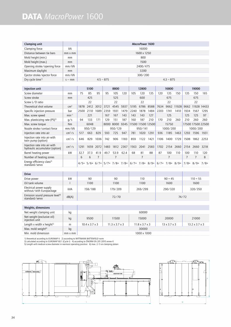
DATA MacroPower 1600
Clamping unit MacroPower 1600
Clamping force kN 16000
Distance between tie bars mm x mm 1600 x 1250
Mold height (min.) mm 800
Mold height (max.) mm 1500
Opening stroke/opening force mm/kN 2400/475
Maximum daylight mm 3200
Ejector stroke/ejector force mm/kN 300/200
Dry cycle time1) s − mm 4.5 – 875 4.3 – 875
Injection unit 5100 8800 12800 16800 19000
Screw diameter mm 75 85 95 95 105 120 105 120 135 120 135 150 135 150 165
Screw stroke mm 425 525 600 675 675
Screw L/D ratio 22 22 22 22 22
Theoretical shot volume cm3 1878 2412 3012 3721 4545 5937 5195 6786 8588 7634 9662 11928 9662 11928 14433
Specific injection pressure bar 2500 2110 1689 2359 1931 1479 2240 1878 1484 2203 1741 1410 1934 1567 1295
Max. screw speed min–1 221 167 167 143 143 143 127 125 125 125 97
Max. plasticizing rate (PS)2) g/s 94 133 171 129 151 187 160 187 210 170 210 260 210 260 260
Max. screw torque Nm 6048 8000 8000 9345 11500 11500 12500 15750 17500 17500 22500
Nozzle stroke/contact force mm/kN 950/129 950/129 950/141 1000/200 1000/200
Injection rate into air cm3/s 517 663 829 593 725 947 781 1020 1291 936 1185 1463 1293 1596 1931
Injection rate into air with twin pump (option) cm3/s 646 829 1036 742 906 1183 859 1122 1421 1106 1400 1729 1508 1862 2253
Injection rate into air with hydraulic accumulator (option) cm3/s 1291 1659 2072 1483 1812 2367 1563 2041 2583 1702 2154 2660 2154 2660 3218
Barrel heating power kW 32.7 37.3 41.9 49.7 53.9 62.4 68 81 88 87 100 110 100 110 120
Number of heating zones 6 6 7 7 7 7 7 7 8
Energy efficiency class3)
standard/servo 4/5+ 5/6+ 6/7+ 5/7+ 7/8+ 7/8+ 6/7+ 7/8+ 8/9+ 6/7+ 7/8+ 8/9+ 7/8+ 8/9+ 7/8+
Drive
Drive power kW 90 90 110 90 + 45 110 + 55
Oil tank volume l 1100 1100 1100 1600 1600
Electrical power supply without/with Europackage kVA 158/188 179/209 269/299 290/320 320/350
Emission sound pressure level4)
standard/servo dB(A) 72/70 74/72
Weights, dimensions
Net weight clamping unit kg 60000
Net weight (exclusive oil) injection unit kg 9500 11500 15000 20000 21000
Length x width x height5) m 10.4 x 3.7 x 3 11.3 x 3.7 x 3 11.8 x 3.7 x 3 13 x 3.7 x 3 13.2 x 3.7 x 3
Max. mold weight6) kg 30000
Min. mold dimension mm x mm 1000 x 1000
1) theoretical according to EUROMAP 6 2) according to WITTMANN BATTENFELD norm 3) calculated according to EUROMAP 60.1 (Cycle I) 4) according to ÖNORM EN 201:2010 annex K5) Length with medium screw diameter in rearmost operating position 6) max. 2/3 on clamping platen
L W
H

35
Wei
terg
abe
sow
ie V
ervi
elfä
ltigu
ng d
iese
s D
okum
ente
s, V
erw
ertu
ng u
nd M
ittei
lung
sein
es In
halts
ist v
erbo
ten,
sow
eit n
icht
aus
drüc
klic
h vo
n W
B W
ittm
ann
Gro
up G
mbH
gest
atte
t. Zu
wid
erha
ndlu
ngen
ver
pflic
hten
zu
Scha
dene
rsat
z. A
lle R
echt
e fü
r den
Fal
lde
r Pat
ent-,
Geb
rauc
hsm
uste
r- od
er G
esch
mac
ksm
uste
rein
tragu
ng v
orbe
halte
n.
Id: S
D-A
AB
F097
- R
ev. a
.3ja
itner
- 05
.08.
2014
, 08:
23Fo
rmat
A3
Wittmann Batteneld
SCHLIESSSEITE MACRO16000_STDA-2542 Kottingbrunn
Freigegeben Hauptdokument
D14
17.07.201404.08.2014
Jaitner
1:501 - 1
Jaitner
Teilenummer Version
Dokumentstatus Dokumentverwendung
Blatt Maßstab
Benennung
Geprüft
Erstellt
Zeichnungsnummer
URHEBERSCHUTZ nach ISO 16016
B-B
A-A
508
660,4
420
560
700
840
980
508
660,
4
420
560
700
840
355,
6
140
203,
2127
355,6
203,2
127
76,2
2694
1000
1000
1600
1250
1868
2910
926
420
67-8
550
050
0
1860 23
67
3267
O 2452168
30
b
300
1070
M36`
60
6950
250
H7
O
250
H7
O
3200
800
1500
960
2400
700
980
700
980
120
260
400
M24-`48(12x)
M24-`48(96x)
O55-`(24x)
M16-`32cO50-`40(2x)
390 590
35943694
16421842
1860
A
A
B
B
140
280
76,2
R 35
2932
2217
280
417
1726

36
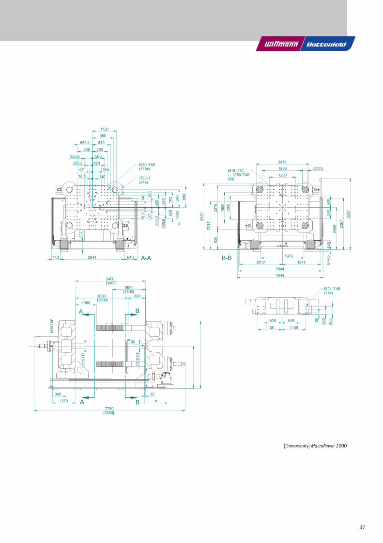
DATA MacroPower 1800/2000
Clamping unit MacroPower 1800 MacroPower 2000
Clamping force kN 18000 20000
Distance between tie bars mm x mm 1850 x 1600
Mold height (min.) mm 800
Mold height (max.) mm 1600 1800
Opening stroke/opening force mm/kN 2600/614 2800/614
Maximum daylight mm 3400 3600
Ejector stroke/ejector force mm/kN 300/200
Dry cycle time1) s − mm 5.8 – 1120 5.5 – 1120
Injection unit 8800 12800 16800 19000
Screw diameter mm 95 105 120 105 120 135 120 135 150 135 150 165
Screw stroke mm 525 600 675 675
Screw L/D ratio 22 22 22 22
Theoretical shot volume cm3 3721 4545 5937 5195 6786 8588 7634 9662 11928 9662 11928 14433
Specific injection pressure bar 2359 1931 1479 2240 1878 1484 2203 1741 1410 1934 1567 1295
Max. screw speed min–1 167 167 143 143 143 127 125 125 125 97
Max. plasticizing rate (PS)2) g/s 129 151 187 160 187 210 170 210 260 210 260 260
Max. screw torque Nm 8000 8000 9345 11500 11500 12500 15750 17500 17500 22500
Nozzle stroke/contact force mm/kN 950/129 950/141 1000/200 1000/200
Injection rate into air cm3/s 742 906 1183 781 1020 1291 1021 1293 1596 1293 1596 1931
Injection rate into air with twin pump (option) cm3/s 816 997 1302 859 1122 1421 1191 1508 1862 1508 1862 2253
Injection rate into air with hydraulic accumulator (option) cm3/s 1483 1812 2367 1563 2041 2583 1702 2154 2660 2154 2660 3218
Barrel heating power kW 49.7 53.9 62.4 68 81 88 87 100 110 100 110 120
Number of heating zones 7 7 7 7 7 8
Energy efficiency class3)
standard/servo 5/6+ 6/7+ 7/8+ 6/7+ 7/8+ 7/8+ 6/7+ 7/8+ 8/9+ 7/8+ 7/8+ 7/8+
Drive
Drive power kW 110 132 110 + 45 110 + 55
Oil tank volume l 1100 1100 1600 1600
Electrical power supply without/with Europackage kVA 200/230 269/299 290/320 320/350
Emission sound pressure level4)
standard/servo dB(A) 74/72
Weights, dimensions
Net weight clamping unit kg 75000 80000
Net weight (exclusive oil) injection unit kg 12000 15000 20000 21000
Length x width x height5) m 12.1 x 4.1 x 3.3 12.6 x 4.1 x 3.3 13.8 x 4.1 x 3.3 14 x 4.1 x 3.3
Max. mold weight6) kg 45000
Min. mold dimension mm x mm 1100 x 1100
1) theoretical according to EUROMAP 6 2) according to WITTMANN BATTENFELD norm 3) calculated according to EUROMAP 60.1 (Cycle I) 4) according to ÖNORM EN 201:2010 annex K5) Length with medium screw diameter in rearmost operating position 6) max. 2/3 on clamping platen
L W
H
37
Wei
terg
abe sowie Vervielfälti
gung dieses Dokum
entes, Verwertung und Mitteilung
seines Inhalts ist verboten, sow
eit nicht ausdrücklich von
WB W
ittmann Group G
mbH
gestat
tet. Zuwiderhandlungen verpflichten zu Schadenersatz. A
lle Rechte für den Fall
der P
atent-, Gebrauchsmuster- oder G
esch
macksmustereintragung vorbehalte
n.
Id: S
D-AACT479 - Rev. a
.1lenz
inge
r - 0
8.08
.2016, 07:12
Form
at A3
Wittmann Batteneld
SCHLIESSSEITE MP20000A-2542 Kottingbrunn
Freigegeben Hauptdokument
ENTWURF!!!!!!!!!!
25.07.201608.08.2016
Lenzinger
1:501 - 1
Lenzinger
Teilenummer Version
Dokumentstatus Dokumentverwendung
Blatt Maßstab
Benennung
Geprüft
Erstellt
Zeichnungsnummer
URHEBERSCHUTZ nach ISO 16016
B-B
A-A
508
660,4
420
560
700
980
1120
508
1600
560
420 84
0
980
355,6
140
203,2127
355,6
127
76,2
2944
1200
1200
1850
1600
2278
3320
926
420
67-85
500
500
2065 23
67
3267
O275
2478
30
b
300
1270
M36
`60
7750[7950]
O315 H7
O315 H7
3400[3600]
800
1600 [1800]
1060
2600[2800]
825
1105
825
1105
120
260
400
M24-`48(12x)
M30-`60(116x)
O55-`(24x)
M16-`32cO50-`40(2x)
440 640
3944
4044
18172017
A
A
B
B
140
280
76,2
R 35
2217
840
70028
0
203,2
417
1976
[Maße] für MacroPower 2000
[Dimensions] MacroPower 2000

38
Gs Gm Gd
xs xd
MOLD DIMENSIONS
» Overview mold weightsThe MacroPower series is laid out for the following maximum mold weights and/or mold torques. If the maximum weight or maximum torque is exceeded, an additional mold support will be necessary. Whenever the values are exceeded, WITTMANN BATTENFELD must be consulted.
machine moveable platen fixed platen center platen
Clamping Unitmax. mold
weightmax.
mold heightmax.
weightmax.
torquemax.
weightmax.
torquemax.
weightmax.
total weight
W (t) (mm) Wm (t) Tm (tm) Wf (t) Tf (tm) Wc (t) Wmax (t)
400, 450 6.5 850 4.3 1.2 3.3 0.7 2.6 9.1
XL 450, 500, 550 8 900 5.3 1.6 4.0 0.9 3.2 11.2
XL 550, 650, 700 10 950 6.7 2.1 5.0 1.2 4.0 14.0
XL 700, 850, 900 12 1000 8.0 2.7 6.0 1.5 4.8 16.8
XL 900, 1000, 1100 19 1200 12.7 5.1 9.5 2.9 7.6 26.6
1300, 1500 30 1400 20.0 9.3 1.0 5.3 12.0 42.0
1600 30 1500 20.0 10.0 15.0 5.6 12.0 42.0
1800, 2000 45 1600 30.0 16 2.5 9.0 18.0 63.0
Wm = 2/3 x WTm = Ws x max. mold h./3Wf = 1/2 x W
Tf = Wf x max. mold h./4Wc = 2/5 x WWmax. = W + Wc
» Mold torque calculation examples MacroPower 850 t clamping force Mold weight W = 11 t
Mold weight clamping side Wm = 7 tDistance to center of gravity xm = 0.3 m
Mold weight on fixed platen side Wf = 4 t Distance to center of gravity xf = 0.2 m
Tm = 7 t x 0.3 m = 2.1 tm Tf = 4 t x 0.2 m = 0.8 tm
All values within specifications, no additional support required.
MacroPower 850 t clamping forceMold weight W = 11 t
Mold weight clamping side Wm = 8 t Distance to center of gravity xm = 0.4 m
Mold weight on fixed platen side Wf = 3 t Distance to center of gravity xf = 0.2 m
Tm = 8 t x 0.4 m = 3.2 tm Tf= 3 t x 0.2 m = 0.6 tm
Value Tm exceeds specification, additional support required.
xm xf
Wm Wc Wf

39
450
500550
XL 550
650700
700XL
850900
XL 900
1000
1100
XL 450
400
1300
1500
1600
1800
2000
300
400
500
600
700
800
900
1000
1100
1200
1300
1400
1500
1600
1700
1800
1900
2000
2100
200 300 400 500 600 700 800 900 1000 1100 1200 1300 1400 1500 1600
Schl
ießk
raft
[t]
Kleinste Werkzeugabmessungen [mm]
Schließkraftreduzierung bei kleinen Werkzeugen MacroPower
REDUCTIONS IN CLAMPING FORCE
» Reductions in clamping force for smaller molds The MacroPower machine series is laid out for minimum mold dimensions as indicated in the technical specifications. Down to the minimum mold size specified, the machine’s clamping force can be fully utilized. When smaller molds are used, the clamping force must be reduced, depending on the mold dimensions, according to the overview below. The mold size used must not fall below the minimum mold dimensions specified in the chart.
» Example of clamping force reduction (chart)MacroPower 850 t clamping force, mold dimensions 700 mm x 800 mm (smaller dimension is relevant). A mold dimension of 700 mm leads to a reduced maximum clamping force of 780 t.
» Mold parallelismThe MacroPower is equipped with high-precision linear guides on the moving platen and therefore guided with extreme accuracy and parallelism across the entire stroke.
Its platen parallelism is within half of EUROMAP 9 tolerance. For correct operation, the maximum parallelism of 0.2 mm with minimum mold dimensions must not be exceeded.
PLEASE NOTE: The molds must be inserted symmetrically to both axes of the clamping platens!
Reductions in clamping force for smaller molds MacroPower
Clam
ping
forc
e [t
]
Minimum mold dimension [mm]
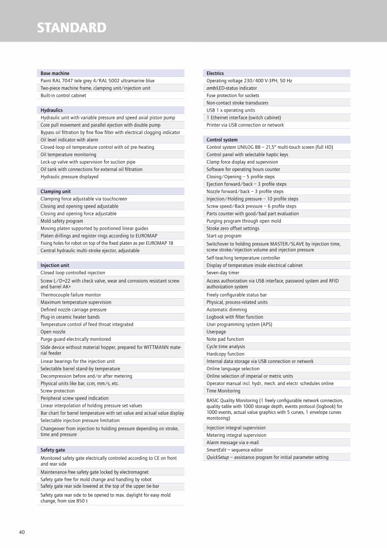
40
STANDARD
Base machinePaint RAL 7047 tele grey 4/RAL 5002 ultramarine blue
Two-piece machine frame, clamping unit/injection unit
Built-in control cabinet
HydraulicsHydraulic unit with variable pressure and speed axial piston pump
Core pull movement and parallel ejection with double pump
Bypass oil filtration by fine flow filter with electrical clogging indicator
Oil level indicator with alarm
Closed-loop oil temperature control with oil pre-heating
Oil temperature monitoring
Lock-up valve with supervision for suction pipe
Oil tank with connections for external oil filtration
Hydraulic pressure displayed
Clamping unitClamping force adjustable via touchscreen
Closing and opening speed adjustable
Closing and opening force adjustable
Mold safety program
Moving platen supported by positioned linear guides
Platen drillings and register rings according to EUROMAP
Fixing holes for robot on top of the fixed platen as per EUROMAP 18
Central hydraulic multi-stroke ejector, adjustable
Injection unitClosed loop controlled injection
Screw L/D=22 with check valve, wear and corrosions resistant screw and barrel AK+
Thermocouple failure monitor
Maximum temperature supervision
Defined nozzle carriage pressure
Plug-in ceramic heater bands
Temperature control of feed throat integrated
Open nozzle
Purge guard electrically monitored
Slide device without material hopper, prepared for WITTMANN mate-rial feeder
Linear bearings for the injection unit
Selectable barrel stand-by temperature
Decompression before and/or after metering
Physical units like bar, ccm, mm/s, etc.
Screw protection
Peripheral screw speed indication
Linear interpolation of holding pressure set values
Bar chart for barrel temperature with set value and actual value display
Selectable injection pressure limitation
Changeover from injection to holding pressure depending on stroke, time and pressure
Safety gate
Monitored safety gate electrically controled according to CE on front and rear side
Maintenance-free safety gate locked by electromagnet
Safety gate free for mold change and handling by robotSafety gate rear side lowered at the top of the upper tie-bar
Safety gate rear side to be opened to max. daylight for easy mold change, from size 850 t
ElectricsOperating voltage 230/400 V-3PH, 50 Hz
ambiLED-status indicator
Fuse protection for sockets
Non-contact stroke transducers
USB 1 x operating units
1 Ethernet interface (switch cabinet)
Printer via USB connection or network
Control systemControl system UNILOG B8 – 21,5'' multi-touch screen (full HD)
Control panel with selectable haptic keys
Clamp force display and supervision
Software for operating hours counter
Closing/Opening – 5 profile steps
Ejection forward/back – 3 profile steps
Nozzle forward/back – 3 profile steps
Injection/Holding pressure – 10 profile steps
Screw speed/Back pressure – 6 profile steps
Parts counter with good/bad part evaluation
Purging program through open mold
Stroke zero offset settings
Start-up program
Switchover to holding pressure MASTER/SLAVE by injection time, screw stroke/injection volume and injection pressure
Self-teaching temperature controller
Display of temperature inside electrical cabinet
Seven-day timer
Access authorization via USB interface, password system and RFID authorization system
Freely configurable status bar
Physical, process-related units
Automatic dimming
Logbook with filter function
User programming system (APS)
Userpage
Note pad function
Cycle time analysis
Hardcopy function
Internal data storage via USB connection or network
Online language selection
Online selection of imperial or metric units
Operator manual incl. hydr., mech. and electr. schedules online
Time Monitoring
BASIC Quality Monitoring (1 freely configurable network connection, quality table with 1000 storage depth, events protocol (logbook) for 1000 events, actual value graphics with 5 curves, 1 envelope curves monitoring)
Injection integral supervision
Metering integral supervision
Alarm message via e-mail
SmartEdit – sequence editor
QuickSetup – assistance program for initial parameter setting

41
OPTIONS
Base machineNon-standard mold height/Opening stroke
Mounting of fast-stroking cylinder exchanged diagonally
Machine frame increased
Hydraulics
Speed controlled servomotor for hydraulic pump to increase the energy efficiency
Hydraulic accumulator for fast injection incl. loading pump
Fast injection with double pump
Injection parallel to clamp force build-up
Hydraulic core pulls. Limit switch function according to EUROMAP 13. Pressure and speeds adjustable
Core pull pressure release
Pneumatic core pull
Hydraulic manifold for Mouldmaster nozzle (controlling 1 nozzle or more, parallelly or sequentially, in the mold)
Pneumatic manifold for Mouldmaster nozzle (controlling 1 nozzle or more, parallelly or sequentially, in the mold)
Ejector pressure/speed controlled by P/Q servo valve
Extra large oil cooler
Filter in water inlet of oil cooler
Adapter with ball valve on the oil tank for oil maintenance
Clamping unitSupport for middle plate or heavy molds
T-slots in mold platens
SPI bolt pattern
Ejector cross in clamping platen as per EUROMAP/SPI
Maximum ejector force increased
Ejector platen safety device
Hydromechanical mold safety mechanism
Air valve, action initiated (ON) and timer (OFF)
Tie-bar retract device for upper tie-bar
Quick mold clamping system electromagnet. or hydr.
Injection unitGrooves in the feeding zone of barrel for improved feeding
High revolution hydraulic screw drive motor
High torque screw motor in lieu of standard
High temperature heaterbands (max. 450 °C)
Barrel insulation (standard up from injection unit 12800)
Screw drive by a.c. servomotor for parallel plastizising
Ball type screw tip
Check valve with carbide insert
Needle type shut-off nozzle operated with spring, pneumatically or hydraulically
Pneumatic cross-bolt type shut-off nozzle
Melt temperature sensor in cylinder head (up to injection unit 8800)
Pressure transducer for melt pressure switch over
Open AIRMOULD®-nozzle, pressure controlled
Wear resistant screw and barrel AKPA for polyamide
Corrosion resistant screw and barrel AKCN in chrome nitride or AKTN titan nitride
High wear and corrosion resistant screw and barrel AK ++
Screw with mixing section or barrier section
Injection unit equipped for rigid PVC
Injection unit equipped for CELLMOULD®
Slide device with spindle/crank handle adjustment (standard up from injection unit 12800)
Material hooper volume 60 liters
Hopper magnet
Access to material hopper via ladder and platform
Safety gateFront side gate safety system for manual part removal
Electric safety gate at the operator side, standard from size 1000 t
Safety gate clearance operator side/rear side extended
Cooling and conditioningFlow controller with temperature gauges
Shut-off valve for cooling water battery
Blow out valve for cooling water battery
Distributor of cooling circuits on the fixed platen and the moving platen Cooling water flow rate integrated into control system via FLOWCON plus
ElectricsTemperature control zone for hot runner
Special voltage
Control cabinet cooler
Additional sockets
Emergency stop button on rear side
Signal tower with acustic element
Temperature control interface digital, serial 20 mA TTY protocol
CAN-Bus-interface for mold conditioner as per EUROMAP 66-2
Interface for BFMOLD® via CAN BUS for WITTMANN D series
Interface for AIRMOULD® mobile
Interface for robots as per EUROMAP 67
Interface for conveyor belt
Interface for dosing pump
RJG eDart interface
Master interface for danger zone boundary (DZB)
Interface for full integration of robot incl. Ethernet switch
Host computer interface/PDA (EUROMAP 63)
Relays contact parallel to plasticizing
Machine fault (potential-free contact)
BNC connectors for injection process analysis
Interface for vacuum pump
Control systemEnergy consumption analysis
Integrated Tandemmould
Switch over to holding pressure by cavity pressure
Switch over to holding pressure by external signal
Injection compression program/venting program
Melt cushion control
Second injection data setting for automatic start up
User specific programable set value limits
Web- and Remote-Service
HiQ-Cushion – melt cushion control
HiQ-Flow – injection integral control
HiQ-Melt – monitoring of material quality
EXPERT Quality Monitoring (4 freely configurable network connections, quality table with 10000 storage depth, events protocol (logbook) for 10000 events, actual value graphic with 16 curves, 4 envelope curves monitoring, SPC charts, trend diagrams)
Additional equipmentLighting in mold space
Europackage
Inline thermography
Webcam
Special paint and/or touch-up paint
Tool kit
Levelling pads
Additional manual on USB flash drive


Mac
roPo
wer
| A
rtic
le n
umbe
r: 30
0593
04 (E
nglis
h) |
201
6/09
| S
ubje
ct to
cha
nge.
| P
rinte
d in
Aus
tria
.
WITTMANN BATTENFELD GmbH
Wiener Neustädter Strasse 81
2542 Kottingbrunn | Austria
Tel.: +43 2252 404-0 | Fax: +43 2252 404-1062
www.wittmann-group.com


![[Wittmann, Andreas] High-performance Quantum Casca](https://img.pdfslide.net/doc/110x75/55cf9712550346d0338f9cdf/wittmann-andreas-high-performance-quantum-casca.jpg)