Embed Size (px)
Citation preview
Macroscopic Particle Model
Madhusuden Agrawal
June 9, 2004
Outline of the Presentation
Introduction to Macroscopic Particle Model (MPM)The Technical Approach and main features of MPMSummary of the MPM UDFCustomized Graphical User Interface for MPMProcedure for MPM case setup and Post Processing in FLUENT v6.1Few Examples (animations) Created Using MPM Scope for Further Enhancements in MPMAvailable to Clients through Fluent’s Consulting Services
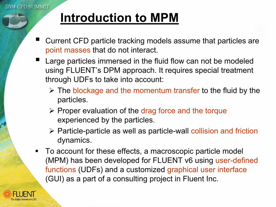
Introduction to MPM
Current CFD particle tracking models assume that particles are point masses that do not interact.Large particles immersed in the fluid flow can not be modeled using FLUENT’s DPM approach. It requires special treatment through UDFs to take into account:
The blockage and the momentum transfer to the fluid by the particles.Proper evaluation of the drag force and the torqueexperienced by the particles.Particle-particle as well as particle-wall collision and frictiondynamics.
To account for these effects, a macroscopic particle model (MPM) has been developed for FLUENT v6 using user-defined functions (UDFs) and a customized graphical user interface(GUI) as a part of a consulting project in Fluent Inc.
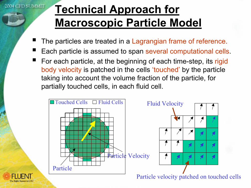
Technical Approach for Macroscopic Particle Model
The particles are treated in a Lagrangian frame of reference.Each particle is assumed to span several computational cells.For each particle, at the beginning of each time-step, its rigid body velocity is patched in the cells ‘touched’ by the particle taking into account the volume fraction of the particle, for partially touched cells, in each fluid cell.
Particle
Particle Velocity
Touched Cells Fluid Cells Fluid Velocity
Particle velocity patched on touched cells
Technical Approach for Macroscopic Particle Model
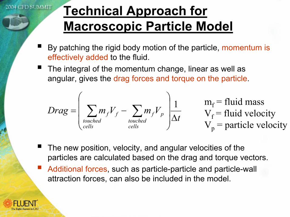
By patching the rigid body motion of the particle, momentum is effectively added to the fluid. The integral of the momentum change, linear as well as angular, gives the drag forces and torque on the particle..
The new position, velocity, and angular velocities of the particles are calculated based on the drag and torque vectors.Additional forces, such as particle-particle and particle-wall attraction forces, can also be included in the model.
tVmVmDrag
cellstouched
pf
cellstouched
ff ∆
−= ∑∑ 1 mf = fluid mass
Vf = fluid velocityVp = particle velocity
Particle-wall collision:Identify the boundary faces the particle intersected during the last timestep (if any).Project incoming particle velocity onto the wall normal and tangential vectors and apply the coefficient of restitution and coefficient of friction to find the final velocities.
Particle-particle collision:Detect which particles are going to collide.Find the line-of-action of the collision, which identifies the normal direction. Project incoming particle velocities onto the line-of-action to get the normal and tangential components.Apply the coefficient of restitution, conservation of momentum and coefficient of friction to the incoming velocities to obtain the final velocities.
Technical Approach for Macroscopic Particle Model
Rotating/Moving WallsMoving/rotating walls require special treatment for particle-wall collision treatment. This effect has been included in the UDF. The UDF will work with the sliding as well as with the moving-deforming mesh (MDM) option.
Continuous Particle StreamUser can define start time, stop time and interval time for eachinjection. The UDF will inject new particles at regular intervals from the start time to stop time. A source term, based on the total volume of fluid displaced per unit time by new injection, for the fluid zone has been included to maintain an overall mass balance
Transient particle data can also be saved in a Fieldview data fileformat.
Technical Approach for Macroscopic Particle Model
The complete UDF has been written to be compatible with the parallel FLUENT solver.User defined memories (UDMs) have been defined for particle radius, particle mass, particle volume fraction, particle drag force, and particle velocity magnitude.The user has the option to switch on or off the interaction of particle motion on the fluid flow.DEFINE_RW_FILE macros have been written in the UDF which will allow user to stop simulation at any time and restart smoothly from a previous data file without any loss of UDF specific data.User can define particle injections in Cylindrical CoordinatesSystem.User can also define rotational and/or translational velocity to injection locations.
Technical Approach for Macroscopic Particle Model
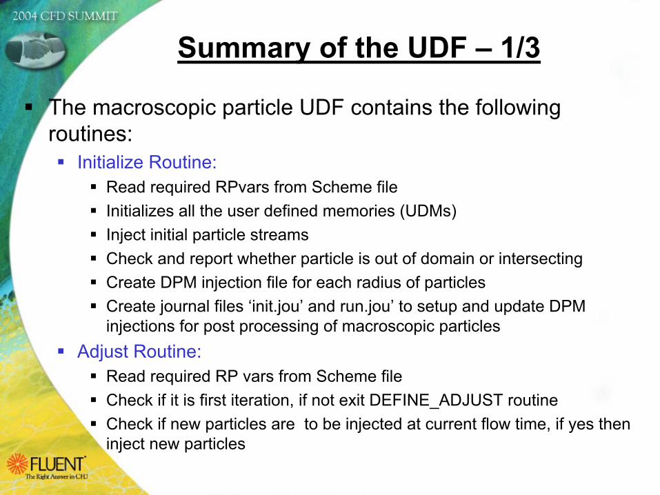
The macroscopic particle UDF contains the following routines:
Initialize Routine:Read required RPvars from Scheme fileInitializes all the user defined memories (UDMs)Inject initial particle streamsCheck and report whether particle is out of domain or intersecting Create DPM injection file for each radius of particlesCreate journal files ‘init.jou’ and run.jou’ to setup and update DPM injections for post processing of macroscopic particles
Adjust Routine:Read required RP vars from Scheme fileCheck if it is first iteration, if not exit DEFINE_ADJUST routineCheck if new particles are to be injected at current flow time, if yes then inject new particles
Summary of the UDF – 1/3
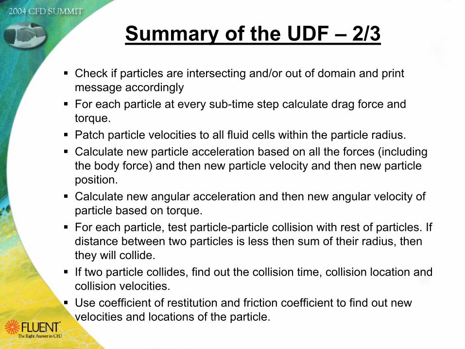
Check if particles are intersecting and/or out of domain and print message accordinglyFor each particle at every sub-time step calculate drag force and torque.Patch particle velocities to all fluid cells within the particle radius.Calculate new particle acceleration based on all the forces (including the body force) and then new particle velocity and then new particle position.Calculate new angular acceleration and then new angular velocity of particle based on torque.For each particle, test particle-particle collision with rest of particles. If distance between two particles is less then sum of their radius, then they will collide. If two particle collides, find out the collision time, collision location and collision velocities.Use coefficient of restitution and friction coefficient to find out new velocities and locations of the particle.
Summary of the UDF – 2/3
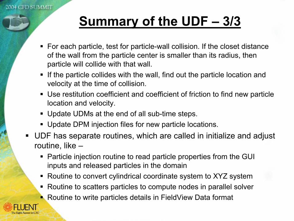
For each particle, test for particle-wall collision. If the closet distance of the wall from the particle center is smaller than its radius, then particle will collide with that wall. If the particle collides with the wall, find out the particle location and velocity at the time of collision. Use restitution coefficient and coefficient of friction to find new particle location and velocity.Update UDMs at the end of all sub-time steps.Update DPM injection files for new particle locations.
UDF has separate routines, which are called in initialize and adjust routine, like –
Particle injection routine to read particle properties from the GUI inputs and released particles in the domainRoutine to convert cylindrical coordinate system to XYZ systemRoutine to scatters particles to compute nodes in parallel solverRoutine to write particles details in FieldView Data format
Summary of the UDF – 3/3
Custom GUI panels were created using Scheme programming for the macroscopic particle model. The Scheme files will also create custom field functions for user defined memoriesThese easy to use custom GUI panels are designed for the user to input all required parameters for the macroscopic particle model, including the particle properties. The next few slides show various features for all the GUI panels in detail.
Customized Graphical User Interface (GUI)
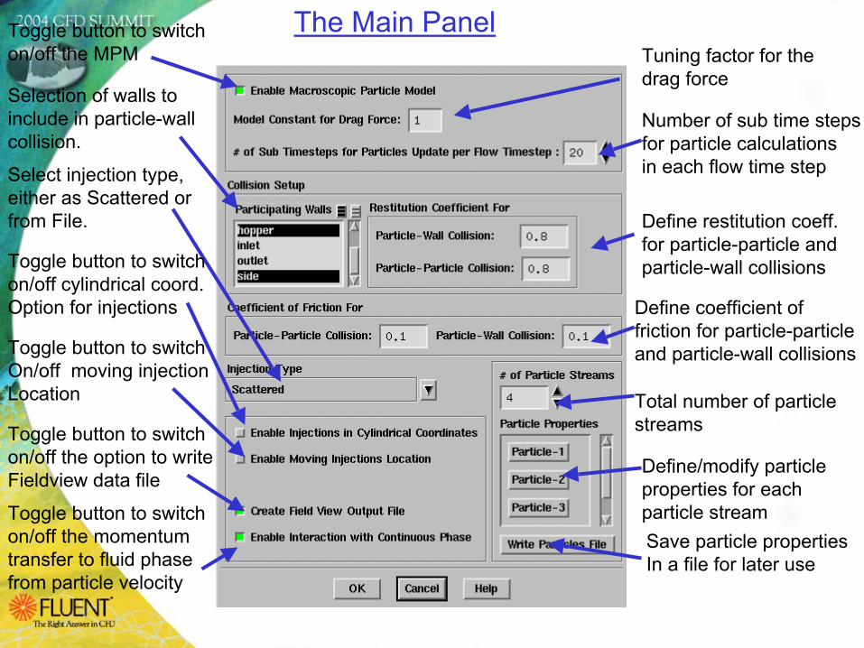
Toggle button to switchon/off the MPM
Toggle button to switchon/off the momentum transfer to fluid phase from particle velocity
Selection of walls toinclude in particle-wallcollision.
Tuning factor for thedrag force
Number of sub time stepsfor particle calculationsin each flow time step
Define restitution coeff.for particle-particle andparticle-wall collisions
Define coefficient offriction for particle-particleand particle-wall collisions
Select injection type, either as Scattered or from File.
Toggle button to switchOn/off moving injectionLocation Total number of particle
streams
Define/modify particleproperties for each particle streamSave particle propertiesIn a file for later use
Toggle button to switchon/off the option to writeFieldview data file
Toggle button to switchon/off cylindrical coord.Option for injections
The Main Panel
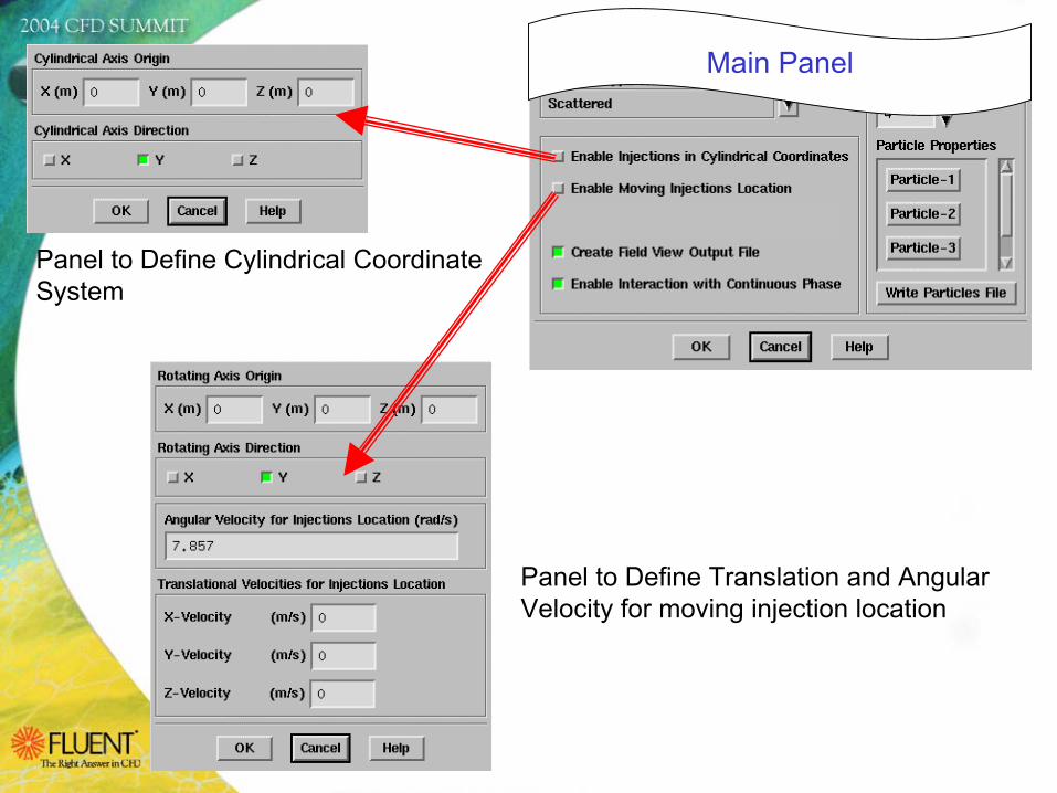
Main Panel
Panel to Define Cylindrical Coordinate System
Panel to Define Translation and AngularVelocity for moving injection location
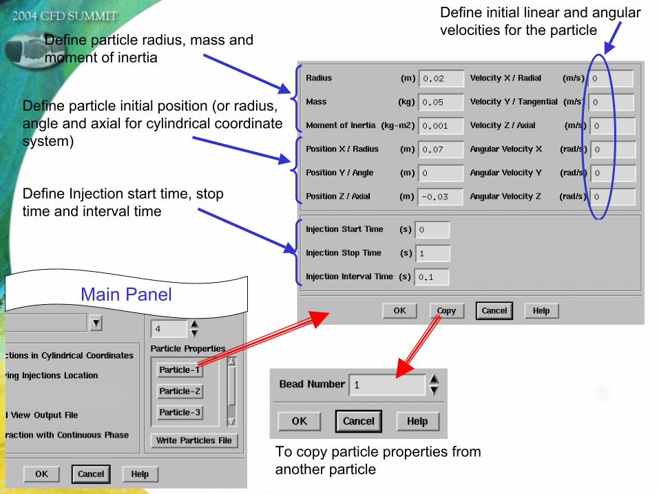
Main Panel
Define particle initial position (or radius, angle and axial for cylindrical coordinate system)
Define initial linear and angular velocities for the particle
Define particle radius, mass and moment of inertia
To copy particle properties from another particle
Define Injection start time, stop time and interval time
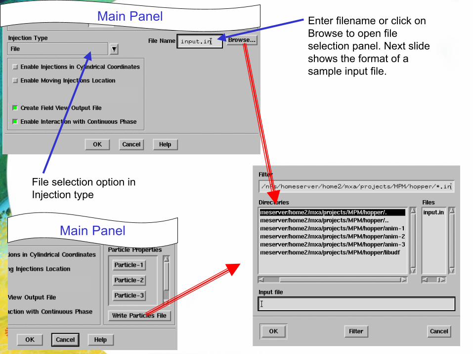
Main Panel
Main Panel
File selection option in Injection type
Enter filename or click on Browse to open file selection panel. Next slide shows the format of a sample input file.
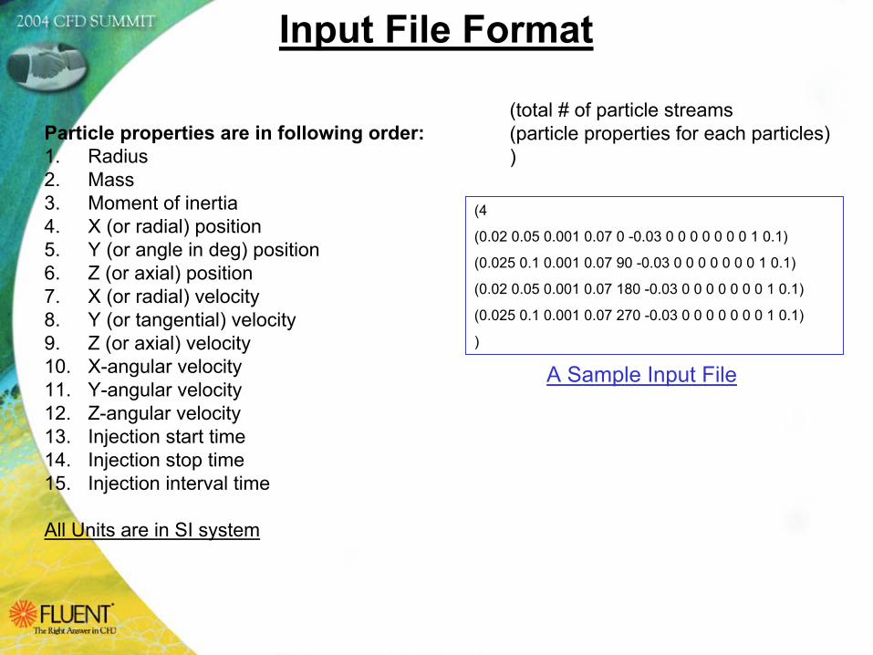
Input File Format
(4
(0.02 0.05 0.001 0.07 0 -0.03 0 0 0 0 0 0 0 1 0.1)
(0.025 0.1 0.001 0.07 90 -0.03 0 0 0 0 0 0 0 1 0.1)
(0.02 0.05 0.001 0.07 180 -0.03 0 0 0 0 0 0 0 1 0.1)
(0.025 0.1 0.001 0.07 270 -0.03 0 0 0 0 0 0 0 1 0.1)
)
Particle properties are in following order:1. Radius 2. Mass 3. Moment of inertia 4. X (or radial) position5. Y (or angle in deg) position6. Z (or axial) position7. X (or radial) velocity8. Y (or tangential) velocity9. Z (or axial) velocity10. X-angular velocity11. Y-angular velocity12. Z-angular velocity13. Injection start time14. Injection stop time15. Injection interval time
All Units are in SI system
A Sample Input File
(total # of particle streams(particle properties for each particles))
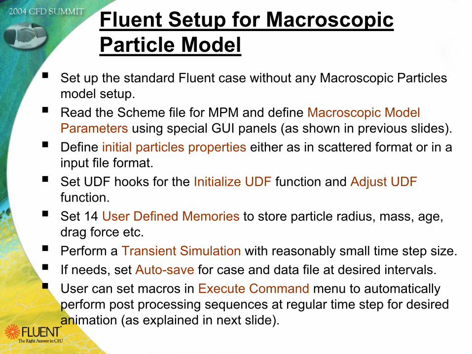
Set up the standard Fluent case without any Macroscopic Particles model setup.Read the Scheme file for MPM and define Macroscopic Model Parameters using special GUI panels (as shown in previous slides). Define initial particles properties either as in scattered format or in a input file format.Set UDF hooks for the Initialize UDF function and Adjust UDFfunction.Set 14 User Defined Memories to store particle radius, mass, age, drag force etc.Perform a Transient Simulation with reasonably small time step size.If needs, set Auto-save for case and data file at desired intervals.User can set macros in Execute Command menu to automatically perform post processing sequences at regular time step for desired animation (as explained in next slide).
Fluent Setup for Macroscopic Particle Model
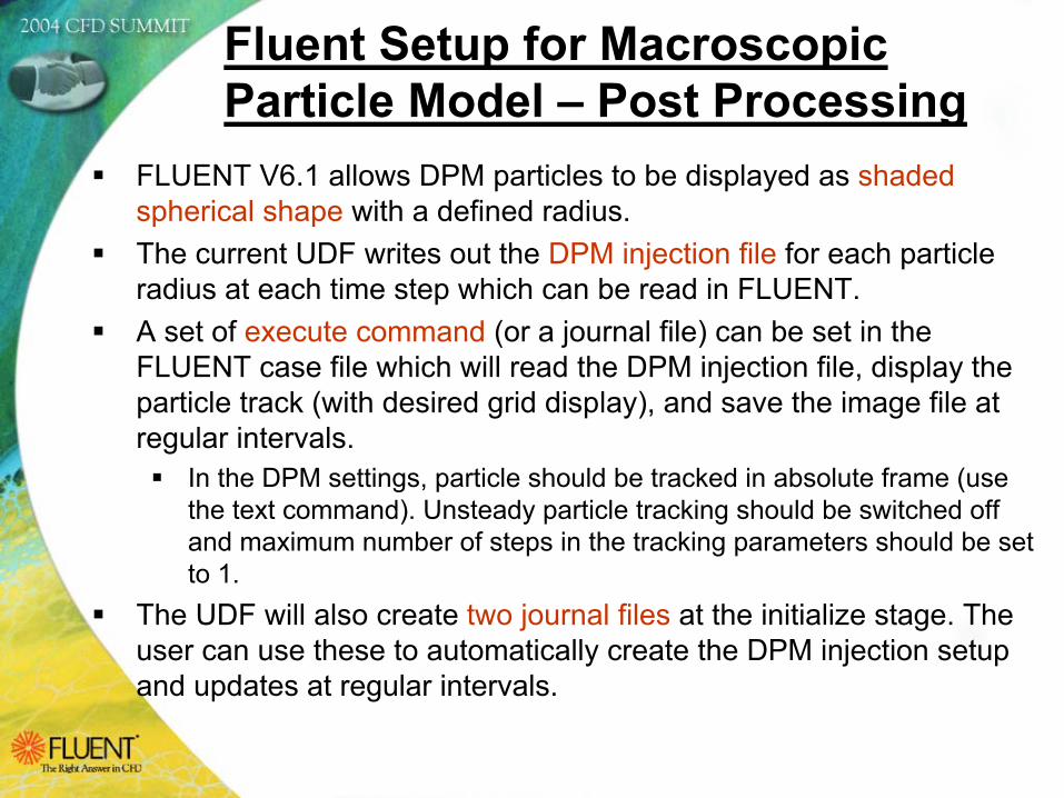
FLUENT V6.1 allows DPM particles to be displayed as shaded spherical shape with a defined radius.The current UDF writes out the DPM injection file for each particle radius at each time step which can be read in FLUENT.A set of execute command (or a journal file) can be set in the FLUENT case file which will read the DPM injection file, display the particle track (with desired grid display), and save the image file at regular intervals.
In the DPM settings, particle should be tracked in absolute frame (use the text command). Unsteady particle tracking should be switched off and maximum number of steps in the tracking parameters should be set to 1.
The UDF will also create two journal files at the initialize stage. The user can use these to automatically create the DPM injection setup and updates at regular intervals.
Fluent Setup for Macroscopic Particle Model – Post Processing
Several test cases were performed using MPM for various application areas. These test cases validate the robustness, convergence and compatibility of the UDF with other models in FLUENT (i.e. sliding mesh, MDM, VOF, laminar, turbulence, etc). These test cases also validate individual features of the model (i.e. friction, collision, continuous injection, moving injection location, post processing etc)Following slides shows animations of these test cases.All these tests produced physically acceptable results.Testing of this model with experimental observation is still need to be done.
Test Examples Created Using MPM
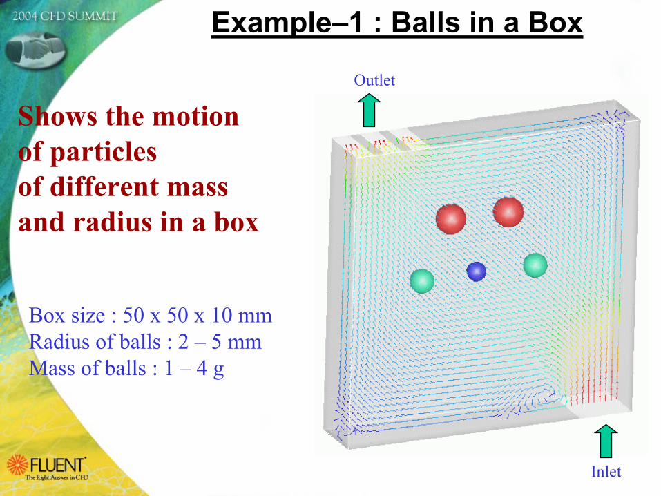
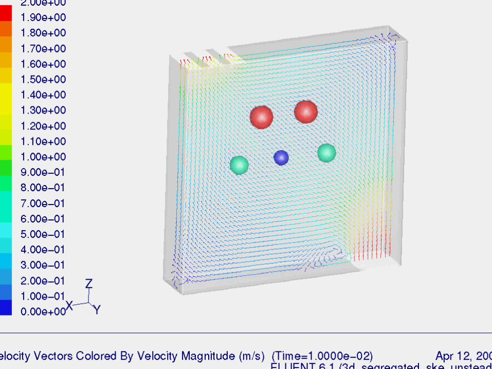
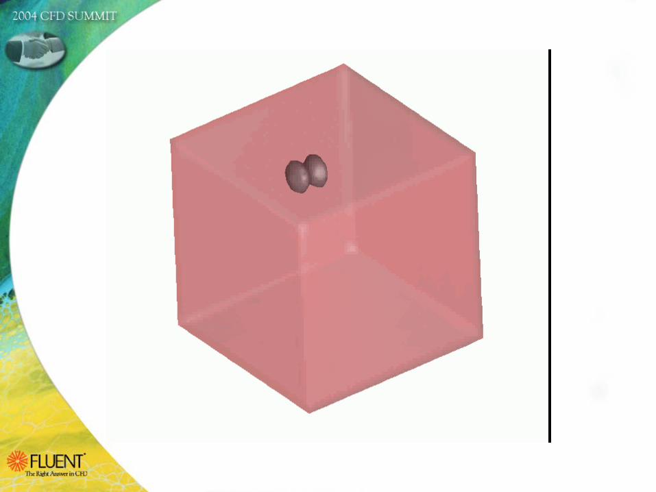
Example–1 : Balls in a Box
Shows the motion of particles of different mass and radius in a box
Inlet
Outlet
Box size : 50 x 50 x 10 mm Radius of balls : 2 – 5 mmMass of balls : 1 – 4 g
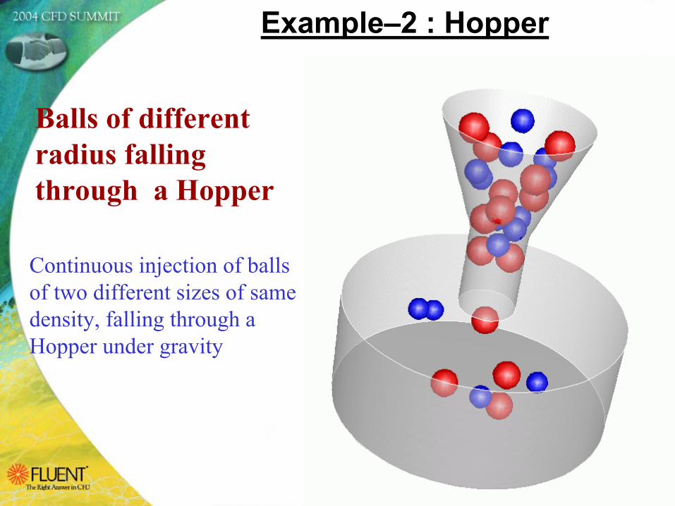
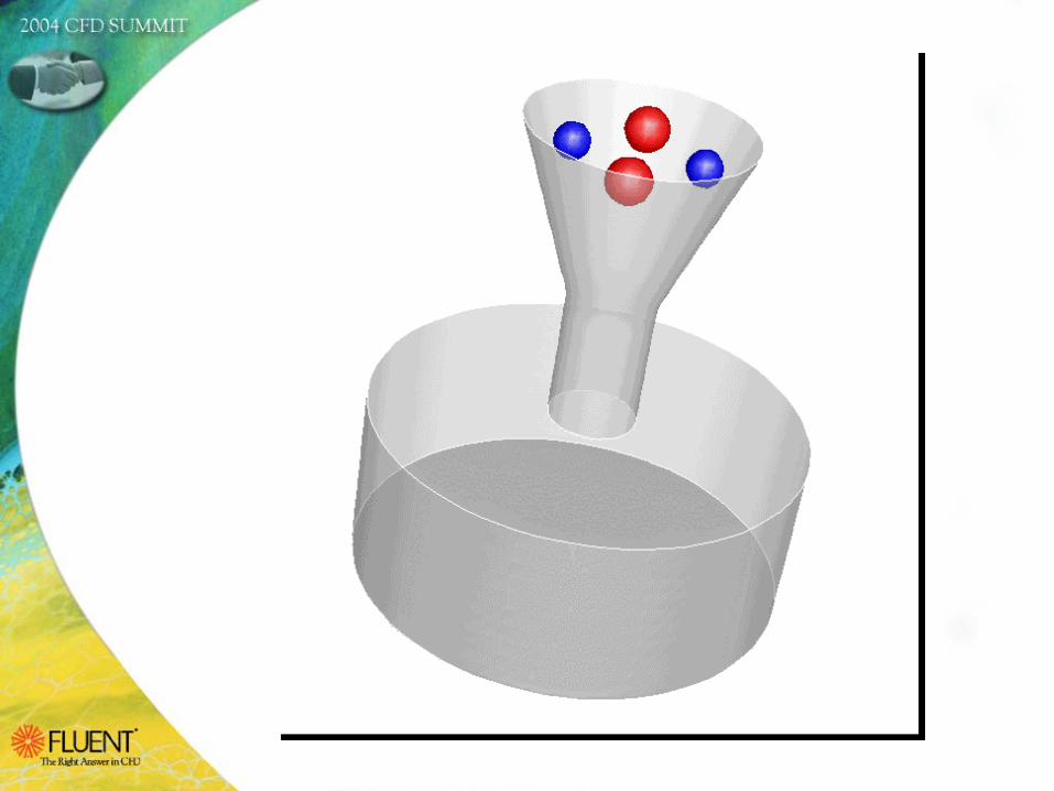
Example–2 : Hopper
Balls of different radius falling through a Hopper
Continuous injection of balls of two different sizes of same density, falling through a Hopper under gravity
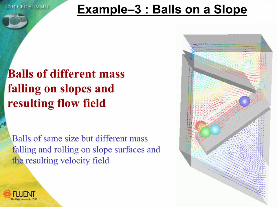
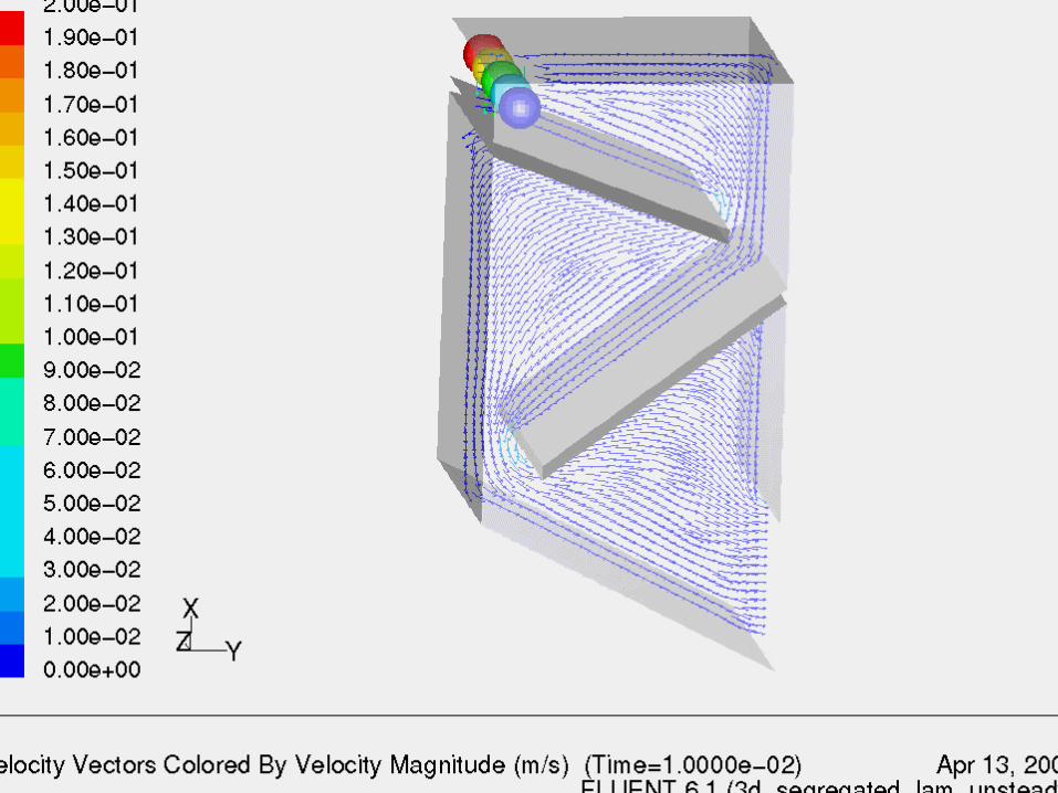
Example–3 : Balls on a Slope
Balls of different mass falling on slopes and resulting flow field
Balls of same size but different massfalling and rolling on slope surfaces and the resulting velocity field
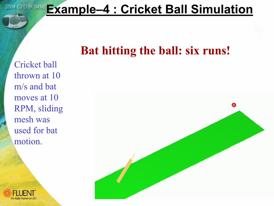
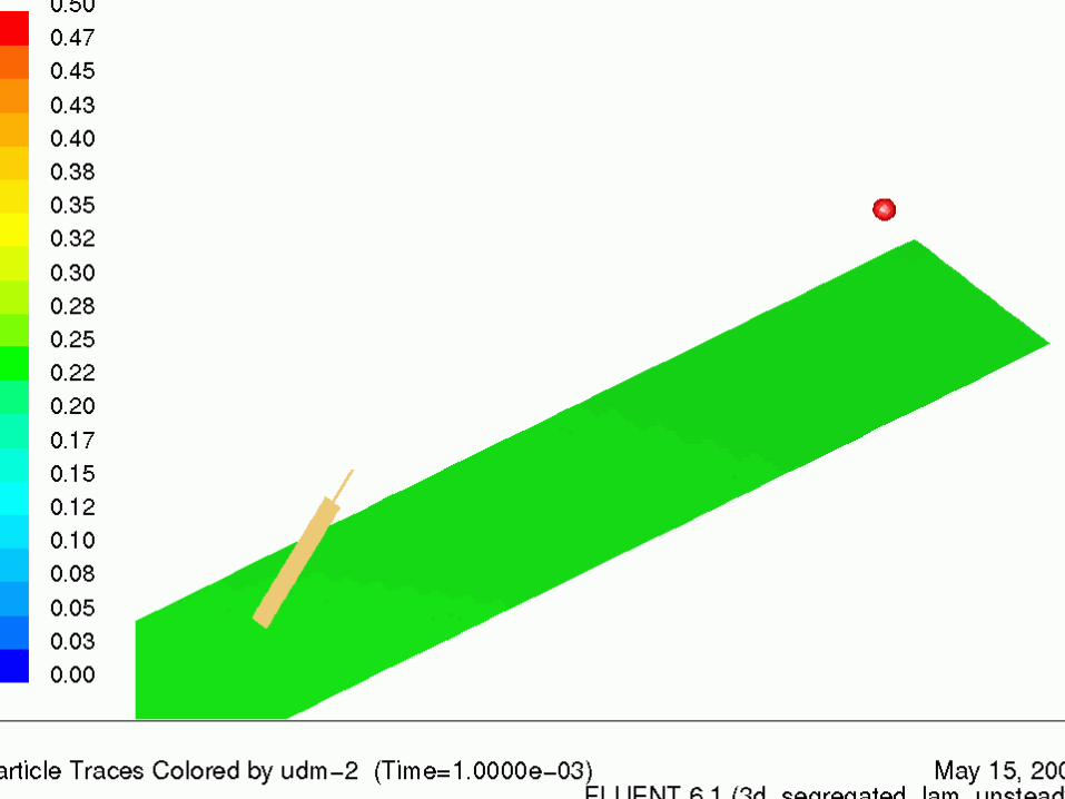
Example–4 : Cricket Ball Simulation
Cricket ball thrown at 10 m/s and bat moves at 10 RPM, sliding mesh was used for bat motion.
Bat hitting the ball: six runs!
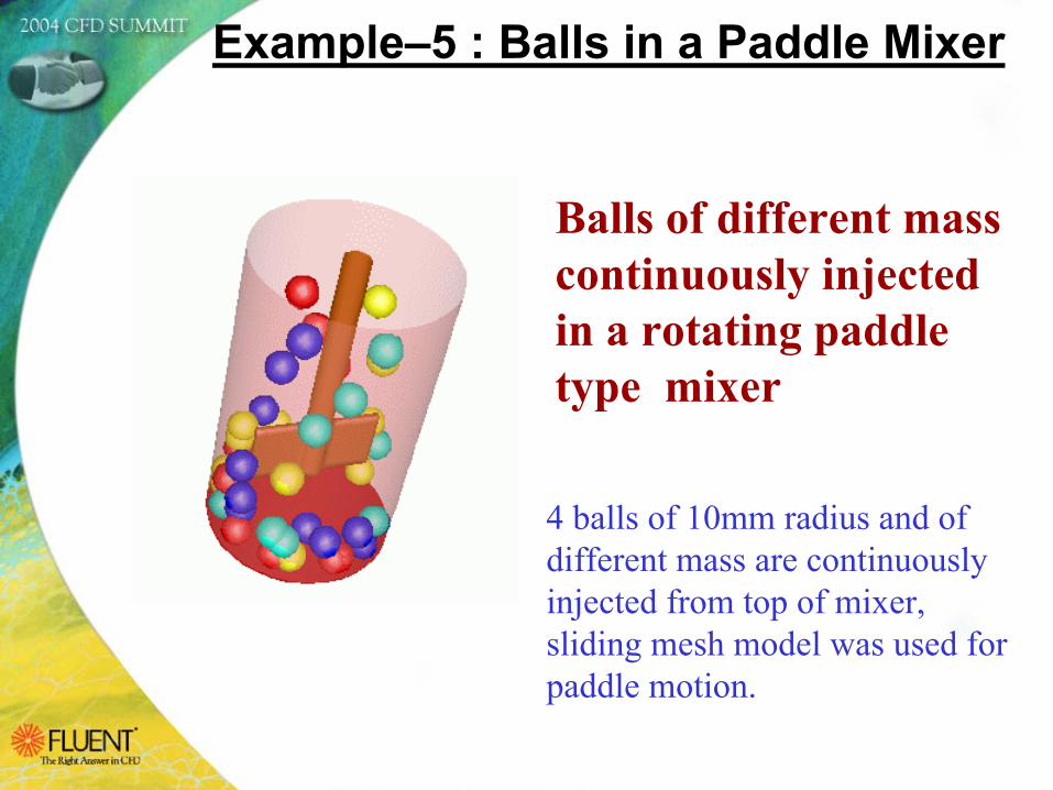
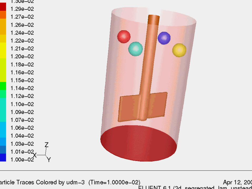
Example–5 : Balls in a Paddle Mixer
Balls of different mass continuously injected in a rotating paddle type mixer
4 balls of 10mm radius and of different mass are continuously injected from top of mixer, sliding mesh model was used for paddle motion.
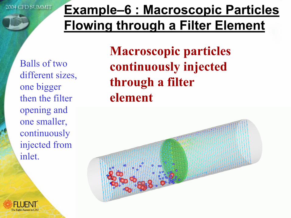
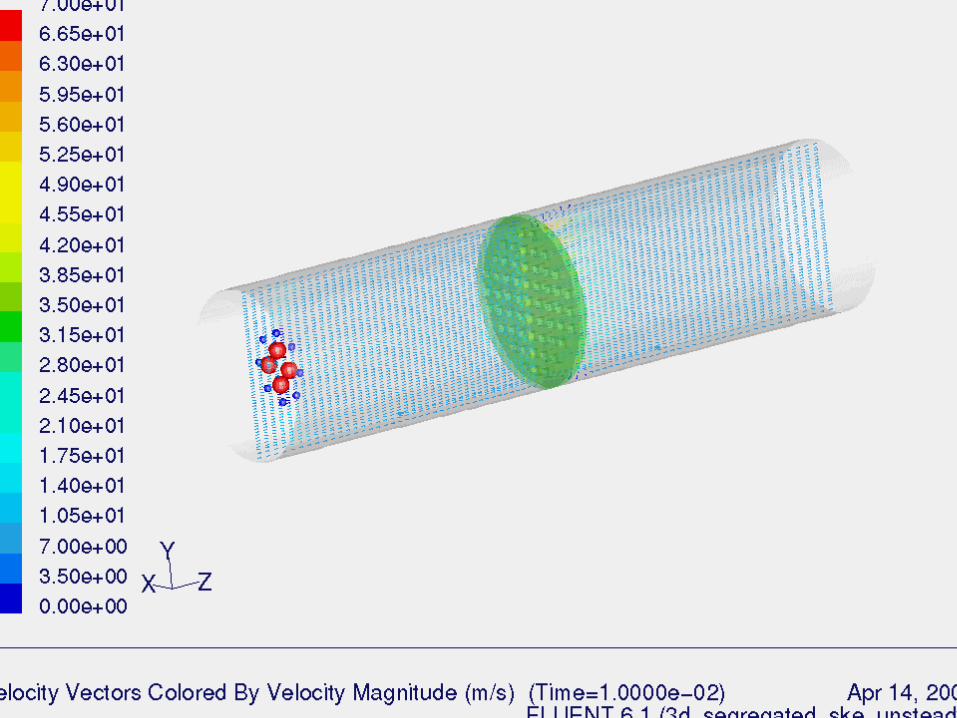
Example–6 : Macroscopic Particles Flowing through a Filter Element
Macroscopic particles continuously injected through a filter element
Balls of two different sizes, one bigger then the filter opening and one smaller, continuously injected from inlet.
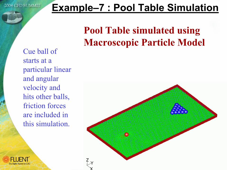
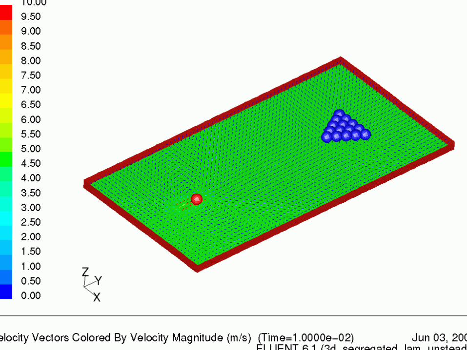
Example–7 : Pool Table Simulation
Pool Table simulated using Macroscopic Particle Model
Cue ball of starts at a particular linear and angular velocity and hits other balls, friction forces are included in this simulation.
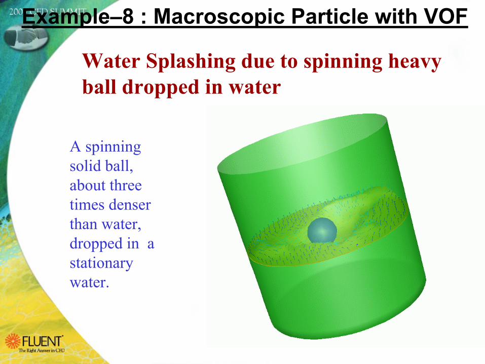
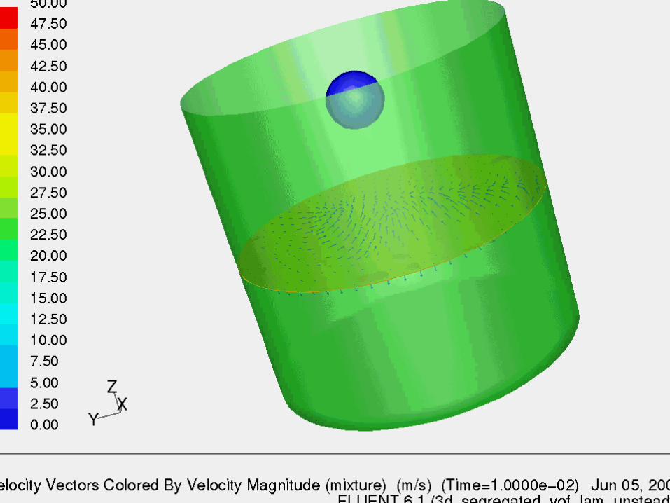
Example–8 : Macroscopic Particle with VOF
Water Splashing due to spinning heavy ball dropped in water
A spinning solid ball, about three times denser than water, dropped in a stationary water.
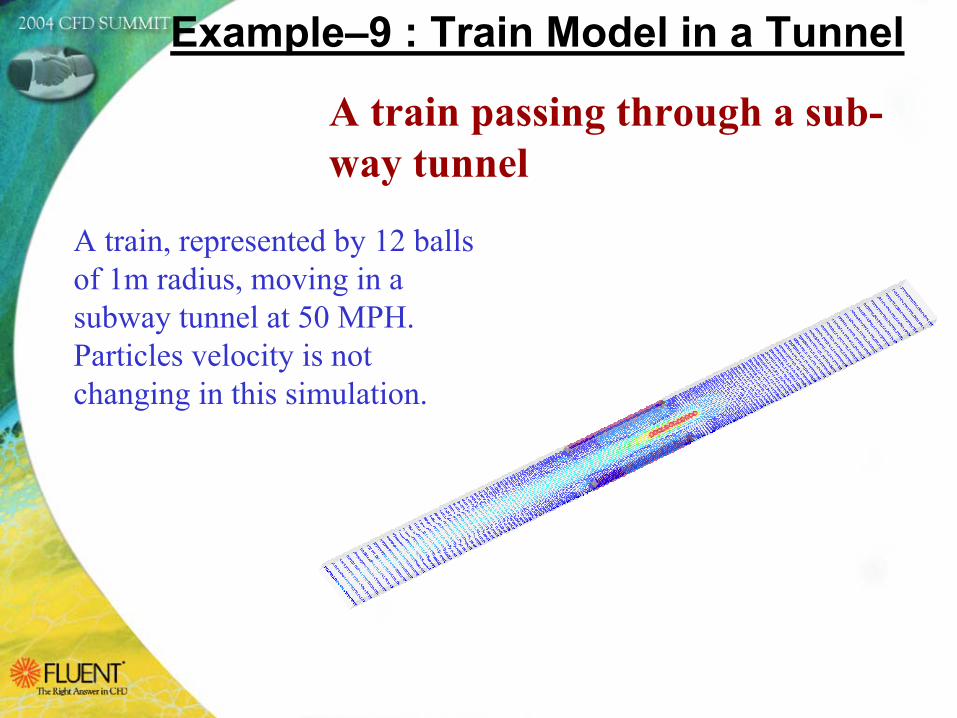
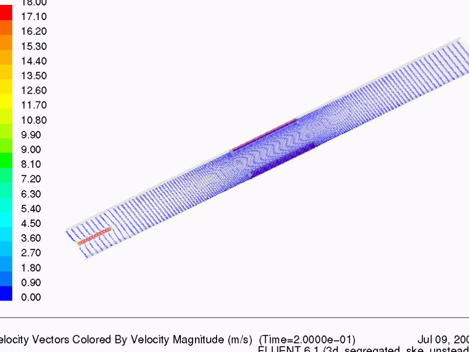
Example–9 : Train Model in a Tunnel
A train passing through a sub-way tunnel
A train, represented by 12 balls of 1m radius, moving in a subway tunnel at 50 MPH. Particles velocity is not changing in this simulation.
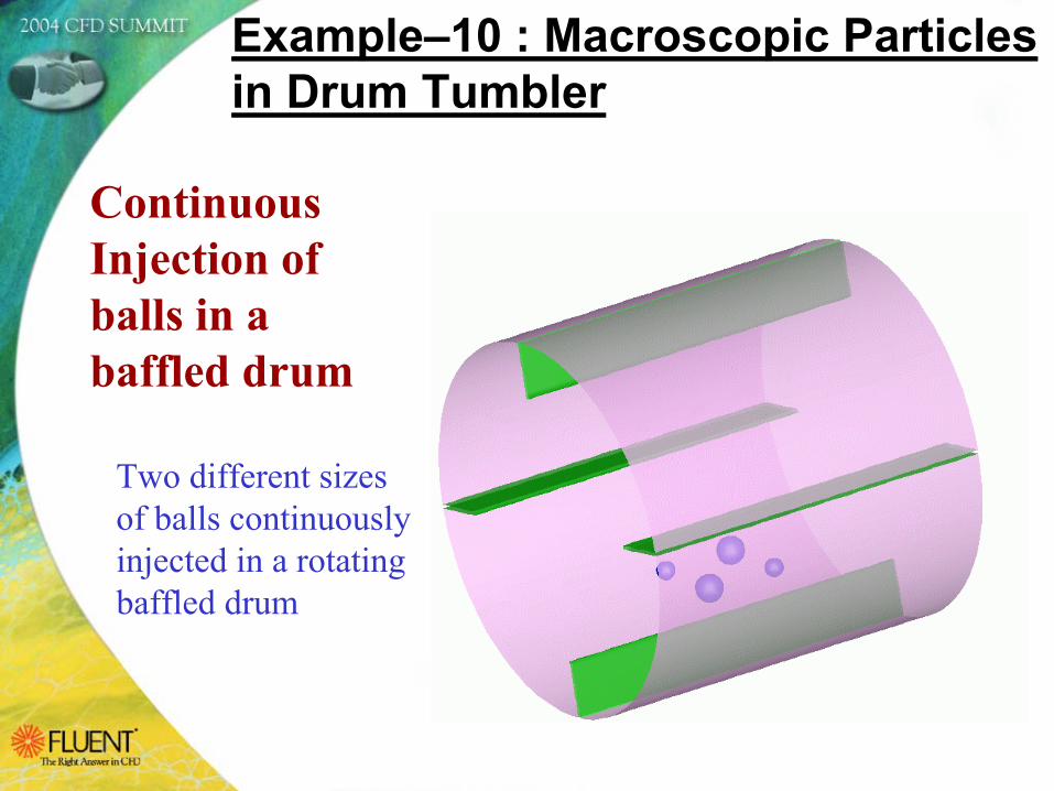
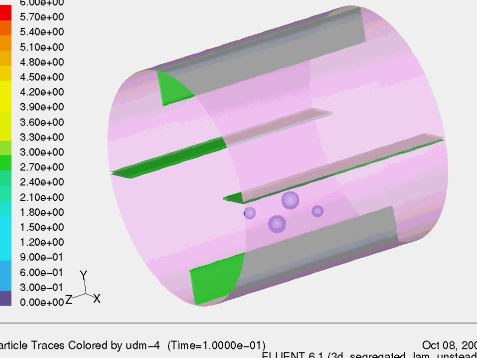
Continuous Injection of balls in a baffled drum
Example–10 : Macroscopic Particles in Drum Tumbler
Two different sizes of balls continuously injected in a rotatingbaffled drum
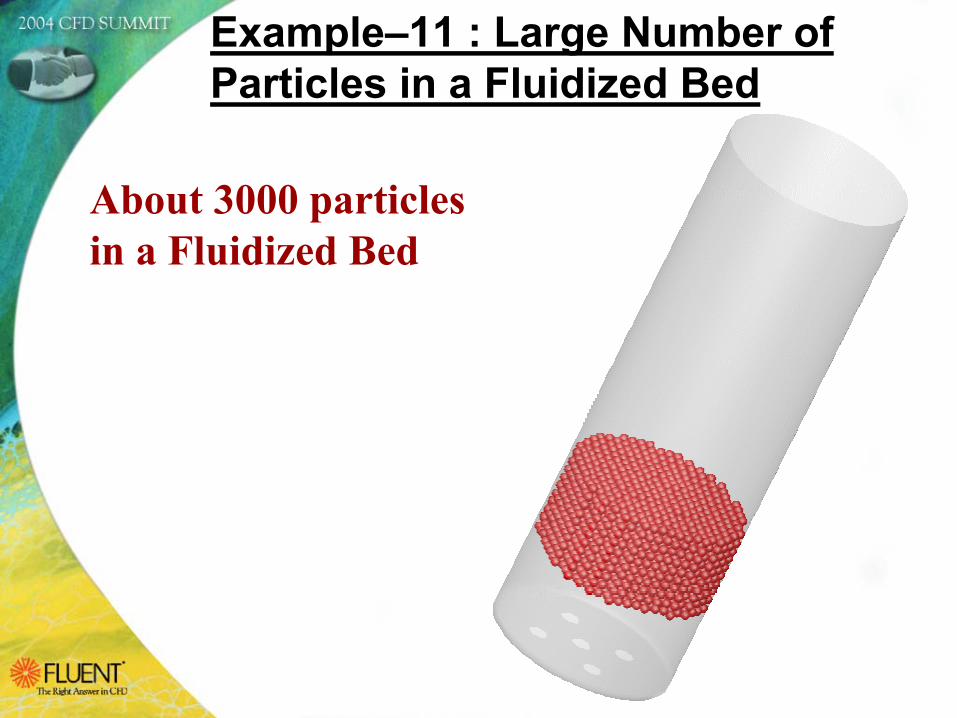
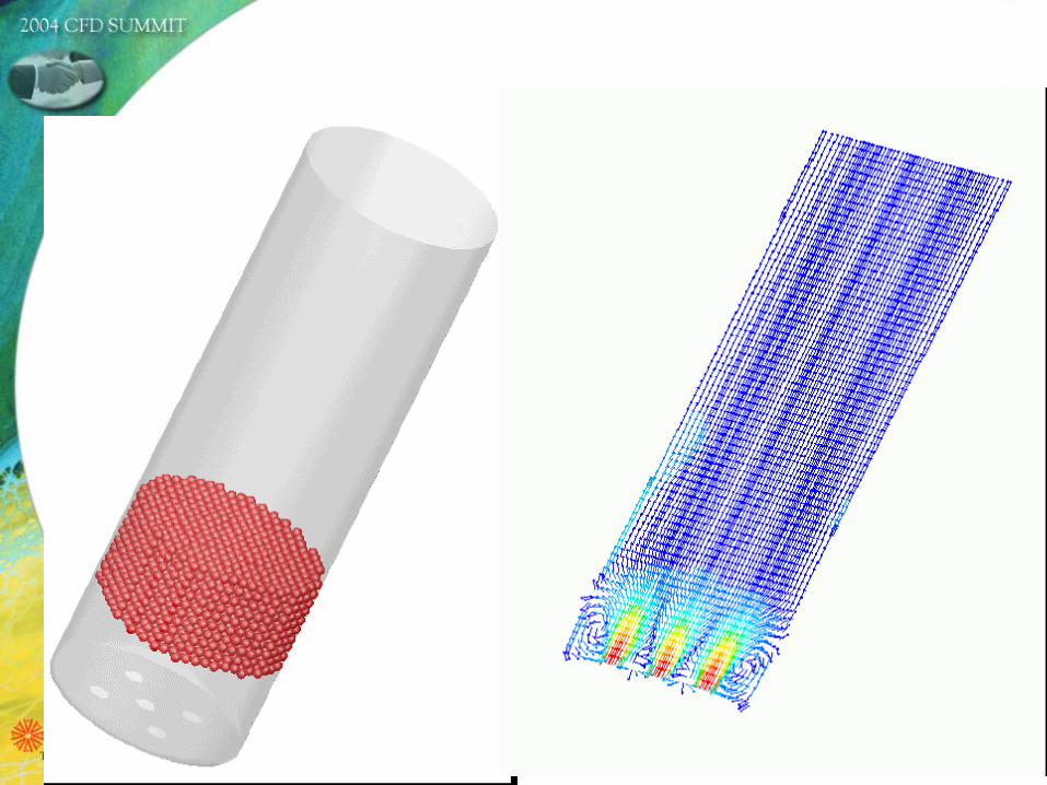
About 3000 particles in a Fluidized Bed
Example–11 : Large Number of Particles in a Fluidized Bed
Scope for Further Enhancements
The MPM has many industrial applications, especially in the pharmaceutical, chemical, material handling, and sports industries. Several validations have been performed. The tests have shown that a large number of particles (up to 10000) can be handled without the need for an excessive computation time.However there are enough scope for further improvements and enhancement in the current Macroscopic Particle Model:
The present formulation can be extended from Spherical Shapedparticles to other regular shapes (cylindrical, ellipsoid, disk, brick…).Heat / Mass Transfer / Chemical reactions between two particles as well as between particle and fluids could be taken into account.Multiple/Group Injections can be added in GUI panel.Particle breakup / agglomeration can also be included in the modelMesh Overset principle along with MDM can be implemented in MPM for an arbitrary shape particle.And many more depending on client’s specific requirements.
Available Through a Consulting Project
Fluent is not planning to include this current MPM module in standard FLUENT at least until v6.3.At present our understanding is that we will not sell this UDF as it is to any client because it is still in the development stage, we don't have proper documentation and training material. We will sell it as part of a consulting project.Any client who wants to use this model for his/her application, he/she will need to use Fluent's consulting services to customized the current UDF to his application and to perform the first simulation, and then we can provide the UDF and related scheme files to the client to perform more cases along with detailed instruction for setup MPM case. Fluent Inc. will retain ownership of the source code of all the UDFsand SCHEME files. Consulting client will receive an unrestrictedlicense to use these UDFs and SCHEME files. Clients will not be allowed to distribute or disclose the content of these UDFs and SCHEME files to third parties