Embed Size (px)
Citation preview

SERVICEManual
Model No.:374.288450
(21-7119)
Treadmill
MADE IN U.S.A.
Prime Fit_"Concourse 10.55 GI
Treadmill by p_p"• Features
• Operation
• Trouble-Shooting
• Parts Replacement
• Adjustments
• Maintenance
• Parts List
• Parts Drawings08-93

TABLE OF CONTENTSFEATURES .................................................... 3
OPERATION ................................................... 4
Grounding Instructions ........................................... 4
Treadmill Operation .............................................. 4
Incline Adjustment ............................................... 4
Fitness Computer Operation ...................................... 6
Using The Pulse Pickup .......................................... 7
Operation Trouble-shooting ....................................... 8
SYSTEM TROUBLE-SHOOTING .................................. 9
Console ....................................................... 9Interface Board ................................................ 9
Motor Controller ................................................ 9
Motor ......................................................... 9
Speed Control System Trouble-shooting ............................. 11
Speed Control System Wiring Diagram .............................. 12
PARTS REPLACEMENT ......................................... 13
Drive Belt, Front Roller, Treadbelt, Treadboard, and rear Roller Replacement 13
Motor/and or Flywheel Pulley Replacement ......................... 14
Motor Controller Replacement ..................................... 14
Interface Board Replacement ...................................... 14
Reed Switch Replacement ........................................ 14
Reset Switch Replacement ........................................ 15
Console, Fitness Computer, and / or Power Switch Replacement .......... 15
Wiring Harness Replacement ..................................... 15
Incline Lever Replacement ........................................ 16Gas Cylinder Replacement ........................................ 16
ADJUSTMENTS ................................................ 17
Treadbelt Adjustment ............................................ 17
Reed Switch Adjustment ......................................... 17Gas Cylinder Adjustment ......................................... 17
MAINTENANCE ................................................ 18
PARTS LIST
Treadmill ...................................................... 19, 20Console ....................................................... 22
PARTS DRAWINGS
Treadmill ...................................................... 21
Console ....................................................... 23
2

FEATURES• New Walk-Thru design features a more compact low profile footprint while offering more useable
running space. More track, less wasted space. 990 square inches of usable space; 10-15%more than most extended profile designs.
• New Hard Body extruded frame provides superior strength; reduces vibration and noise.
• New Soft Step cushioned low impact deck with massaging effect.
• New Fast Track display features special visual graphics including a 1/4 mile trac and tachopulse graph. The extra large 2 1/2" x 4 3/4" LCD id fully programmable and allows continuousviewing of time, speed, distance, pulse and calories. Fast Trac also features Fitness Index, acomputer calculated index that allows the user to monitor their fitness level.
• Side mounted 2 HP DC motor from G.E. featuring the new Silent Mountsystem to reduce noiseand vibration.
• Includes Power Key (start/stop) for easy-to-use safe operation.
• Gas assist incline allows you to adjust the percent grade for a more demanding workout.
• Speed range of 0.5 to 10.0 mph. FAST TRAC• Made In U.S.A. DISPLAY
POWERKEY
CUSHIONEDDUAL
HANDRAILS
ADJUSTMENTLEVER
SOFT STEPCUSHIONED
LOW IMPACT DECK(TREADBOARD)
TREADBELT
HARDBODYEXTRUDED
FRAME(SIDERAILS)
SIDE MOUNTED2 HP DC MOTOR
FIGURE 1

OPERATION• This TREADMILL is intended for home use only.
Be sure your TREADMILL is sitting on a level surface.The TREADMILL should be plugged into a three prong (grounded) outiet in a 115/120 volt-60 Hz AC circuit separatefrom all other appliances - see GROUNDING INSTRUCTIONS.
GROUNDING INSTRUCTIONSThis product must be grounded. If it should malfunction or breakdown, grounding provides a path of least resistancefor electric current to reduce the risk of electric shock. The plug must be plugged into an appropriate outlet that isproperly installed and grounded in accordance with all local codes and ordinances.
WARNING -- Improper connection of the equipment-grounding conduc-tor can result in a risk of electric shock.
GROUNDEDOUTLET
Check with a qualified electrician or serviceman if you are in doubt as to whetherthe product is properly grounded. Do not modify the plug provided with the product GROUNDED-- if.it will not fit the outlet, have a proper outlet installed by a qualified electrician. PIN __
This product uses a nominal 120 volt circuit and has a grounding plug that lookssimilar to the plug illustrated.
No plug adapter should be used with this product. __,_pL :G_ _The use of an extension cord with this product is not recommended, but if anextension cord is needed, use a short (less than ten feet), heavy gauge (14 gauge Uor better) extension cord with a three prong (grounded) plug and receptacle.
TREADMILL OPERATIONNOTE: Before operating your treadmill, become familiar with all operating parts and controls - their location andfunction - see FIGURE 3.
Step 1.
Step 2.
Step 3.
Step 4.
Step 5.
To Operate
CA UTION--To avoid injury, hold onto HANDRAILS while mounting and dismounting TREADMILL.
Place feet on SlDERAILS. Do notatand on TREADBELT. Securely attach POWER KEY CLIP to yourclothing. If you slip or fall while exercising, POWER KEY will pull out of CONSOLE, turning power off.
Insert POWER KEY fully into SLOT in CONSOLE, to turn treadmill's power "ON".
Push SPEED CONTROL UP BUTTON to adjust treadmill to slowest speed (0.5 mph).
Step onto TREADBELT and begin walking.
Push SPEED CONTROL UP BUTTON until you reach your desired speed.NOTE: The TREADMILL is capable of speeds from around "0.5" to "10" miles per hour. Due to manufacturertolerances, the upper and lower speed limits may vary by + or - 0.2 mph. The speed is read from the DISPLAYin the CONSOLE.
Step 1.
Step 2.
Step 3.
Step 4.
To StopPush SPEED CONTROL DOWN BUTTON to adjust treadmill to slowest speed (0.5 mph)
Hold onto HANDRAILS and place feet on SIDERAILS.
Push STOP / PAUSE BUTTON.
Remove POWER KEY, to turn treadmill's power "OFF".
To Adjust Incline
CA UTION-- POWER KEY must be removed before incline adjustments are made.
RAISING .... Dismount the treadmill, pull up the INCLINE LEVER and release when the treadmill reaches thedesired incline angle.
LOWERING - - - Mount the treadmill, pull up the INCLINE LEVER and release when the treadmill reaches thedesired incline angle.
4

OPERATIONFAST TRAC SPEED CONTROL
FITNESS COMPUTER UP/DOWN BUTTONS
SELECTDISPLAY \,,i BUTTONS
J
STOP/PAUSEBU1-FON
INCLINELEVER
POWERKEY
POWER
KEY _
CLIP FITNESSINDEX
BUTTON
OPERATOR'S VIEWof CONSOLE
\
HANDRAILS
CONSOLE
TREADBELT
SlDERAILS
FIGURE 2TREADBELT
ADJUSTMENTSCREWS 5
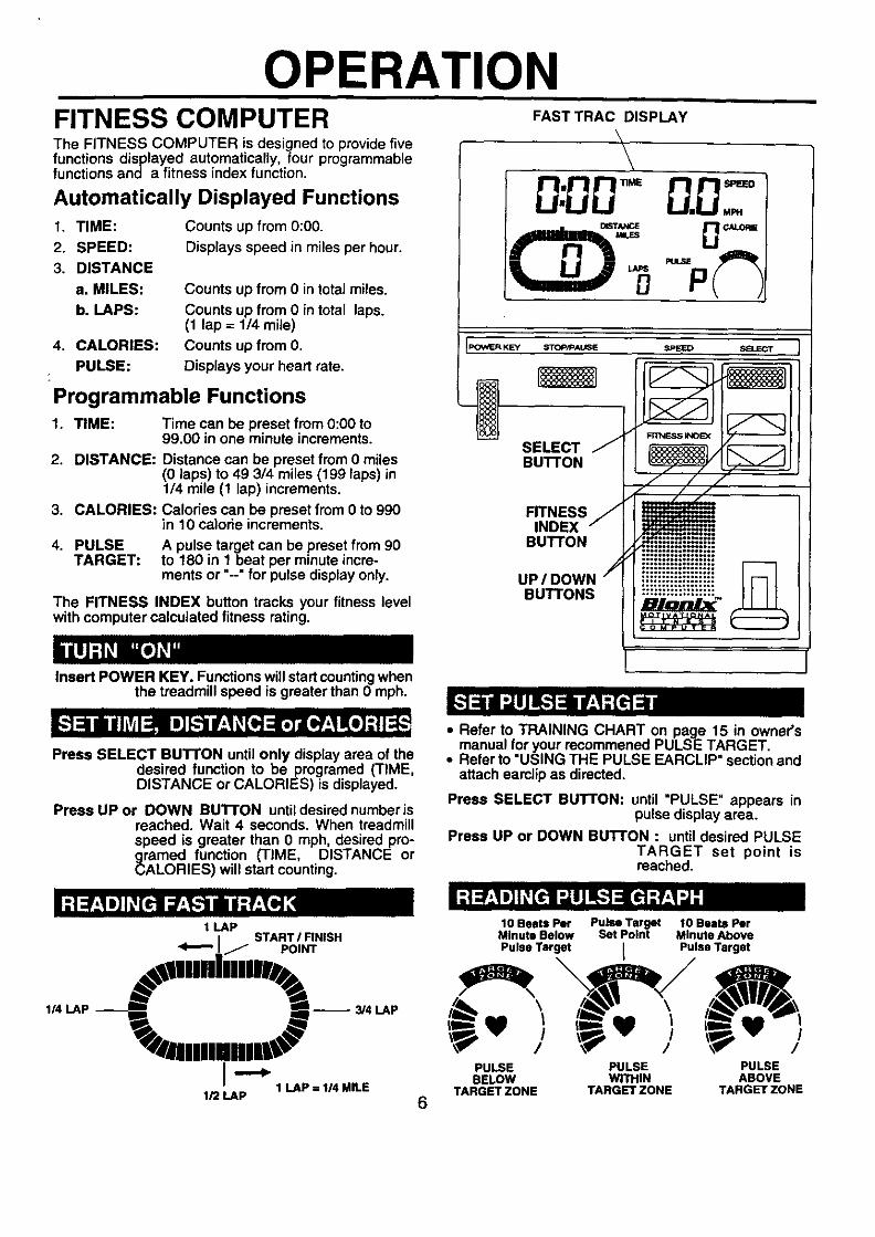
OPERATIONFITNESS COMPUTERThe FITNESS COMPUTER is designed to provide fivefunctions displayed automatically, four programmablefunctions and a fitness index function.
Automatically Displayed Functions1. TIME:
2. SPEED:
3. DISTANCE
a. MILES:
b. LAPS:
4. CALORIES:
PULSE:
Counts up from 0:00.
Displays speed in miles per hour.
Counts up from 0 in total miles.
Counts up from 0 in total laps.(1 lap = 114 mile)
Counts up from 0.
Displays your heart rate.
Programmable Functions1. TIME: Time can be preset from 0:00 to
99.00 in one minute increments.
2. DISTANCE: Distance can be preset from 0 miles(0 laps) to 49 3/4 miles (199 laps) in1/4 mile (1 lap) increments.
3. CALORIES: Calories can be preset from Oto 990in 10 calorie increments.
4. PULSE A pulse target can be preset from 90TARGET: to 180 in 1 beat per minute incre-
ments or "--" for pulse display only.
The FITNESS INDEX button tracks your fitness levelwith computer calculated fitness rating.
Insert POWER KEY. Functions will start countingwhenthe treadmill speed is greater than Omph.
Press SELECT BUTrON until only display area of the
KEY
SELECTBUTTON
FITNESSINDEX
BUTTON
UP/DOWNBUTTONS
I
desired function to beprogramed (TIME,DISTANCE or CALORIES) is displayed.
Press UP or DOWN BUTTON until desired numberisreached. Wait 4 seconds. When treadmillspeed is greater than 0 mph, desired pro-_amed function (TIME, DISTANCE or
LORIES) will start counting.
1 LAP
• Refer to TRAINING CHART on page 15 in owner'smanual for your recommened PULSE TARGET.
• Refer to "USING THE PULSE EARCLIP" section andattach eamlip as directed,
Press SELECT BUTTON: until "PULSE" appears inpulse display area.
Press UP or DOWN BUTTON : until desired PULSETARGET set point isreached.
START I FINISHIj POINT
!lllllillilW
,.LAP---j m-- ,LAP
1/2 LAP1 LAP = 1/4 MILE
6
10Beats Per Pulse Target 10 Bests PerMinute Below Set Point Minute Above
Pulse Target I Pulse Target
_ v i _ v / \_ v /\_" / \_" / \_" /
PULSE PULSE PULSEBELOW WITHIN ABOVE
TARGET ZONE TARGETZONE TARGETZONE

OPERATION
The FITNESS INDEX button tracks your fitness levelwith computer calculated fitness rating. The FitnessComputer will calculate your fitness rating from 0 (Poor)to 10 (Good).
Your level of fitness is determined by your pulse rate.As you fitness level increases you will find that you willneed to walk or jog faster to stay in the pulse range youhave chosen. The FITNESS INDEX button gives youfeedback to your increasing fitness level.NOTE: You must stay consistant in your workouts inorder to get an accurate and consistant fitness rating.
Refer to "USING THE PULSE EARCLIP" section andattach earclip as directed.
After completing your workout, remain still with earclipattached.
Press FITNESS INDEX button. 0:60 will appear inTIME display area. Time willcount down to 0:00 and Fit-ness Computer will calcu-late your fitness rating fromOto 10.
Using The PULSE EARCLIP
CA UTION -- This pulse earclip is not a medi-cal device. Readings may not always be accurate. Bestreadings may be obtained in a still, relaxed position.
IMPORTANT-- When exercising in a vig-orous manner the erratic movement of the PULSEEARCLIP or CABLE may cause the "P" to appear in thePULSE window indicating incorrect pulse readings. Tryto keep the PULSE EARCLIP and CA BLE from uneces-sary movement when exercising.
1. Insert EARCLIP PLUG into EARCLIP RECEPTACLEon back of CONSOLE - see DETAIL "A".
2. Attach STRAIN RELIEF CLIP to your cellar or otherpiece of clothing - see DETAIL "B".]Y..Q.TJ_:EARCLIP CABLE must not be aflowed to be
in a strain.
3. Massage EARLOBE to increase circulation.
4. Attach EARCLIP to EARLOBE in a vertical position -see DETAIL "C".
5. When exercise has been completed remove EAR-CLIP from earlobe and clip it to EARCLIP CABLE.
DETAIL "A"
\\
\
COLLAR """\
-. EARCLIP-.. / CABLE
/:/
STRAIN RELIEF CLIP
/
DETAIL "B"
/._- _-.// // -, •
/_: EARLOBEEARCLIP
DETAIL "C"7

OPERATION
1.
2.
3.
4.
5.
6.
7.
8.
9.
10.
11.
12.
Treadmill Will Not Start.
Treadbelt Does Not Run InCenter Of Roller.
Treadbelt Slips While In Use.
Treadbelt Hesitates WhenStepped On.
Treadmill Makes "Rumbling"Noise.
Treadmill Makes "whining"Noise.
Treadmill Is Difficult To Roll.
Black Particles CollectingUnder Treadmill.
No Display On FitnessComputer in Console.
Fitness Computer Does NotDisplay Speed Or Distance.
Fitness Computer Shuts Off.
No Pulse Displayed OnFitness Computer.
OPERATION TROUBLE-SHOOTING
il. ! Not Plugged In.
i2.[ House Circuit BreakerTripped.
3. Treadmill Reset SwitchTripped.
4. Unit Plugged Into InsufficientExtension Cord.
5. Inadequate Voltage At Outlet.
1. Treadbelt Tension Not EvenAcross The Treadbelt.
1. Treadbelt Tension Too Light.
1. Insufficient Lubricant OnTreadbelt.
1. Treadbelt Tensioned TooHigh.
1. Walking Too Close To TheEdge Of Treadbelt.
1. Treadmill On Thick Carpeting.
1. Drive Belt Is Breaking In.
1. Treadmill Not Plugged InAnd Power Key Not InsertedInto Console.
1. Reed Switch Not AlignedProperly.
1. Magnet Damaged Or MissingFrom Pulley on t-ront Roller.
2. Reed Switch Not WorkingProperly.
! 3. Fitness Computer Not[ Working Properly.
21 Pulse Earclip Not PluggedInto Console.
Pulse Earclip Not ProperlyAttached To Earlobe.
3.
4.
Pulse Earclip In DirectSunlight
Pulse Earclip Is MovingAround Too Much.
Plug Into Three Prong (grounded)115/120 Volt-60 Hz AC Outlet - SeeTreadmill Grounding.
Reset Or Replace Fuse.
Reset Treadmill Reset Switch.
Plug Directly Into Wall Outlet OrUse Short (less Than Ten Feet),Heavy Gauge (t4 Gauge Or Better)Extension Cord.
Have Qualified Electrician CheckVoltage.
See - "Treadbelt Adjustment" onpage 17.
See - "Treadbelt Adjustment" onpage 17.
See "Maintenance" on page 18.
Loosen Treadbelt Ad ustment BoltsTill Noise Ceases But Treadbe tDoes Not Slip While In Use.
Bring Stride Back Towards CenterOf Treadbelt.
Move To Hard Surface Or Low CutCarpeting.
Vacuum Under TreadmillPeriodically
Plug Into Three Prong (grounded)115/120 Volt-60 Hz AC Outlet - SeeTreadmill Grounding. Insert PowerKey. Adjust Treadbelt Speedgreater than 0 mph.
See -"Reed Switch Adjustment" onpage 17.
Replace Magnet.
Replace Reed Switch.
i 3. I Replace Fitness Computer.
r 1. ! Plug Pulse Earclip Into Back oft
i Console.
2. Massage Earlobe To IncreaseCirculation And Reattach PulseEarclip.- See "Using The Pulse
3. I Earclip" On Page 7.Place Pulse Earclip On Earlobe. I Away From Direct Sunlight.I 4. Use Strain Relief Clip And Try Not
I To Move Head Erratically - SeeDETAIL "B" On Page 7.
IF OTHER PROBLEMS ARE ENCOUNTERED OR ANY PROBLEMS CAN NOT BE CORRECTED, PLEASECALL OUR SERVICE DEPARTMENT TOLL FREE AT 1-800-473-7247.
8
TROUBLESHOOTINGConsole and Motor System
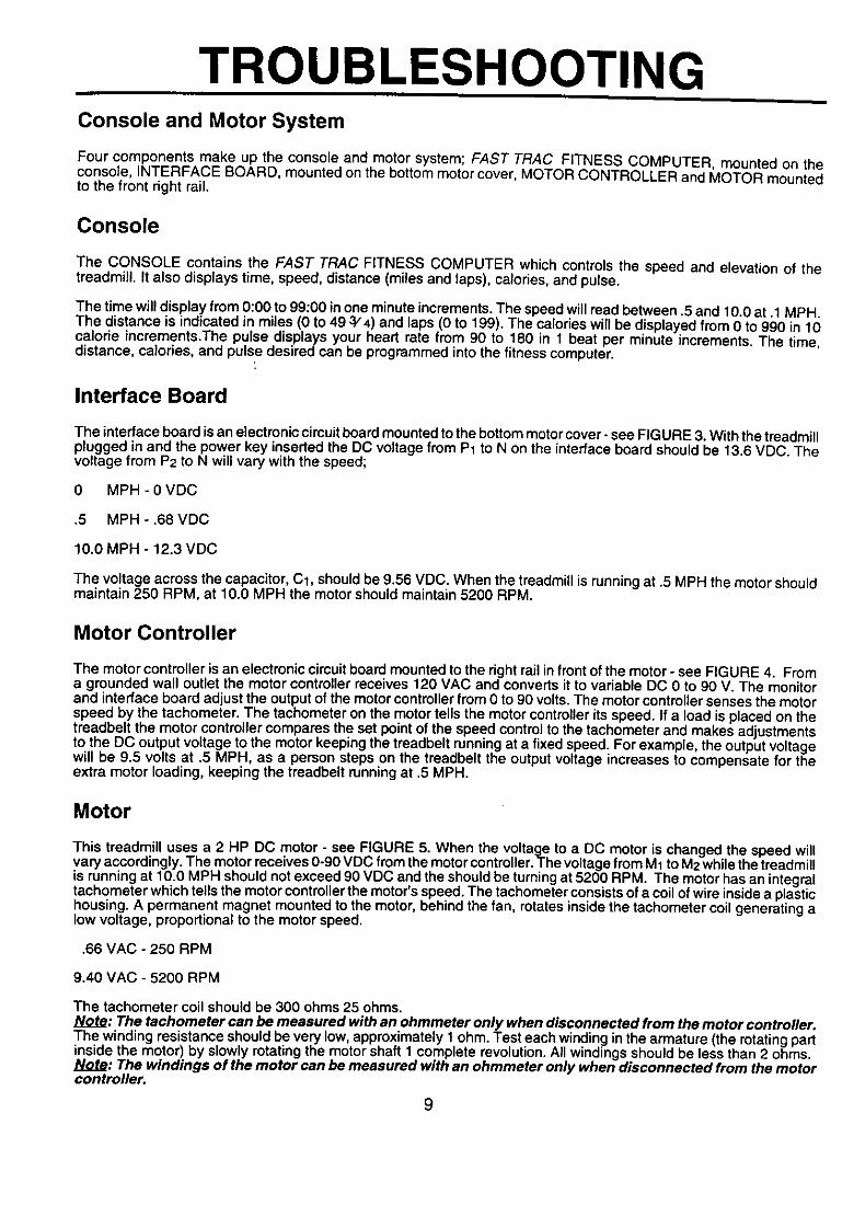
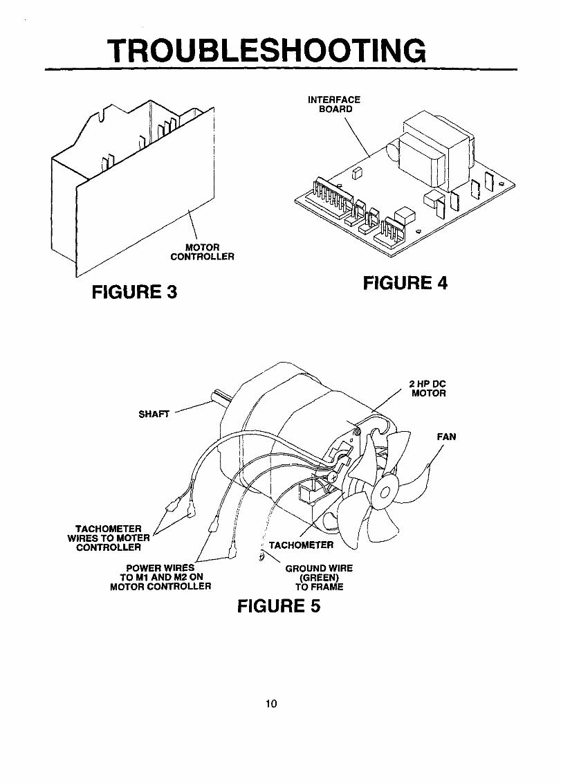
Four components make up the console and motor system; FAST TRAC FITNESS COMPUTER, mounted on theconsole, INTERFACE BOARD, mounted on the bottom motor cover, MOTOR CONTROLLER and MOTOR mountedto the front right rail.
Console
The CONSOLE contains the FAST TRAC FITNESS COMPUTER which controls the speed and elevation of thetreadmill. It also displays time, speed, distance (miles and laps), calories, and pulse.
The time will display from 0:00 to 99:00 inone minute increments. The speed will read between .5 and 10.0 at .1 MPH.The distance is indicated in miles (0 to 49 3/4) and laps (0 to 199). The calories will be displayed from 0 to 990 in 10calorie increments.The pulse displays your heart rate from 90 to 180 in 1 beat per minute increments. The time,distance, calories, and pulse desired can be programmed into the fitness computer.
Interface Board
The interface board is an electronic circuitboard mounted to the bottom motor cover- see FIGURE 3. With the treadmillplugged in and the power key inserted the DC voltage from PI to N on the interface board should be 13.6 VDC. Thevoltage from P2 to N will vary with the speed;
0 MPH - 0 VDC
.5 MPH - .68 VDC
10.0 MPH - 12.3 VDC
The voltage across the capacitor, Cl, should be 9.56 VDC. When the treadmill is running at .5 MPH the motor shouldmaintain 250 RPM, at 10.0 MPH the motor should maintain 5200 RPM.
Motor Controller
The motor controller is an electronic circuitboard mounted to the right rail in front of the motor - see FIGURE 4. Froma grounded wall outlet the motor controller receives 120 VAC and converts it to variable DC 0 to 90 V. The monitorand interface board adjust the output of the motor controller from 0 to 90 volts. The motor controller senses the motorspeed by the tachometer. The tachometer on the motor tells the motor controller its speed. If a load is placed on thetreadbelt the motor controller compares the set point of the speed control to the tachometer and makes adjustmentsto the DC output voltage to the motor keeping the treadbelt running at a fixed speed. For example, the output voltagewill be 9.5 volts at .5 MPH, as a person steps on the treadbelt the output voltage increases to compensate for theextra motor loading, keeping the treadbelt running at .5 MPH.
Motor
This treadmill uses a 2 HP DC motor - see FIGURE 5. When the voltage to a DC motor is changed the speed willvary accordingly. The motor receives 0-90 VDC from the motor controller. The voltage from M1to M2 while the treadmillis running at 10.0 MPH should not exceed 90 VDC and the should be turningat 5200 RPM. The motor has an integraltachometer which tells the motor controller the motor's speed. The tachometer consists of a coil of wire inside a plastichousing. A permanent magnet mounted to the motor, behind the fan, rotates inside the tachometer coil generating alow voltage, proportional to the motor speed.
.66 VAC - 250 RPM
9.40 VAC - 5200 RPM
The tachometer coil should be 300 ohms 25 ohms.Note: The tachometer can be measured with an ohmmeter only when disconnected from the motor controller.The winding resistance should be very low, approximately 1 ohm. Test each winding in the armature (the rotating partinside the motor) by slowly rotating the motor shaft 1 complete revolution. All windings should be less than 2 ohms.Note: The windings of the motor can be measured with an ohmmeter only when disconnected from the motorcontroller.
9
TROUBLESHOOTING
INTERFACEBOARD
\
MOTORCONTROLLER
FIGURE 3 FIGURE 4
SHAFT
2 HP DCMOTOR
FAN
TACHOMETERWIRESTO
CONTROLLER
POWER WIRESTO M1 AND M2 ON
MOTOR CONTROLLER
r
,' TACHOMETER
GROUND WIRE(GREEN)
TO FRAME
FIGURE 5
10
1.
2.
3.
4.
5°
6.
7.
8.
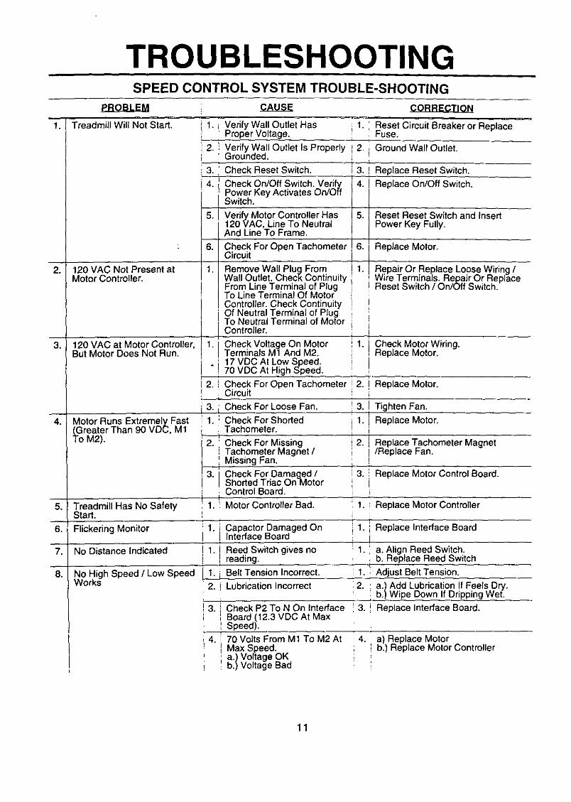
TROUBLESHOOTINGSPEED CONTROL SYSTEM TROUBLE-SHOOTING
EB-O-B-LEM :
Treadmill Will Not Start. 1. Verify Wall Outlet Has 1,Proper Voltage.
2. i Verify Wall Outlet Is Properly ,_2.Grounded. i
i Check Reset Switch. i 3.
Check On/Off Switch. VerifyPower Key Activates On/OffSwitch.
120 VAC Not Present atMotor Controller.
120 VAC at Motor Controller,But Motor Does Not Run.
Motor Runs Extremely Fast(Greater Than 90 VDC, M1To M2).
' Reset Circuit Breaker or ReplaceFuse.
i Ground Walt Outlet.
3. i Replace Reset Switch.
Replace On/Off Switch.
5. Verify Motor Controller Has 5. Reset Reset Switch and Insert120 VAC, Line To Neutral Power Key Fully•And Line To Frame.
6, 6. Replace Motor.Check For Open TachometerCircuit
1.
i2.
j3•[1.J
12.
l
Repair Or Replace Loose Wiring /Wire Terminals. Repair Or ReplaceReset Switch / On/Off Switch.
I, 1. ' Check Motor Wiring.Replace Motor.
• iI
i
2. Replace Motor.
i 3. Tighten Fan.I
r! 1. x Replace Motor.i P
2. Replace Tachometer Magnet/Replace Fan.
3. Replace Motor Control Board.
Remove Wall Plug FromWall Outlet. Check ContinuityFrom Line Terminal of PlugTo Line Terminal Of MotorController. Check Continuity
i Of Neutral Terminal of PlugTo Neutral Terminal of MotorI Controller.
I Check Voltage On MotorTerminals M1 And M2.
i 17 VDC At Low Speed.70 VDC At High Speed.
I
'_Check For Open Tachometeri Circuit
j Check For Loose Fan.
i Check For ShortedTachometer.I
Cheek For MissingTachometer Magnet /_ Missing Fan.
! 3. Check For Damaged /
l Shorted Triac OnMotorControl Board.I
1. Motor Controller Bad.
i 1. Capactor Damaged OnI Interface Board
! 1. Reed Switch gives noreading.
i
! 1. j Belt Tension Incorrect.r
[ 2. i Lubrication Incorrect
Treadmill Has No Safety 1. Replace Motor ControllerStart.
Flickering Monitor 1. i Replace Interface Board
No Distance Indicated
No High Speed / Low SpeedWorks
! 3. _ Check P2 To N On Interface 3.! Board (12.3 VDC At Max
I '1 Speed).
14. 1_ 70 Volts From M1 To M2 At : 4.I Max Speed.
' i a.) Voltage OK! b.) Voltage Bad
1 a. Align Reed Switch.• '=b. Replace Reed Switch
lI 1. } Adjust Belt Tension.2. a.) Add Lubrication If Feels Dry.
b.) Wipe Down If Dripping Wet.
Replace Interface Board.
a) Replace Motorb.) Replace Motor Controller
11
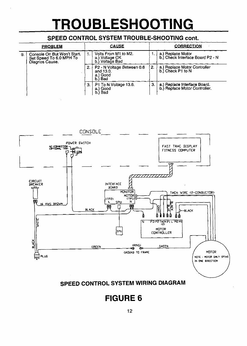
9.
TROUBLESHOOTINGSPEED CONTROL SYSTEM TROUBLE-SHOOTING cont.
Console On But Won't Start.Set Speed To 6.0 MPH ToDiagnos Cause.
.
2.
3.
Volts From M1 to M2.
_:/Voltag eOKVoltage Bad
P2 - N Voltage Between 0.6and 13.0.
_:}GoodBad
P1 To N Voltage 13.6.
_:IGoodBad
, £._.BBE.C_T_IQN
t. a.) Replace Motor
lb.) Check Interface Board P2 - N
2. b)a?CheckReplacep1M°t°rtoN Controller
a.) Replace Interface Board.b.) Replace Motor Controller.
CONSOLE
POWER SWITCHNO ¢_t_CTl(_l(OP'f tONaL "f_])-'_
CIRCUITBREAKER
_. 16 AVG BROWN
I PLUG
INTERFACE
BOARD
(TLP2)
FAST TRAC DISPLAY
FITNESS COMPUTER
]
SPEED CONTROL SYSTEM WIRING DIAGRAM
FIGURE 6
12
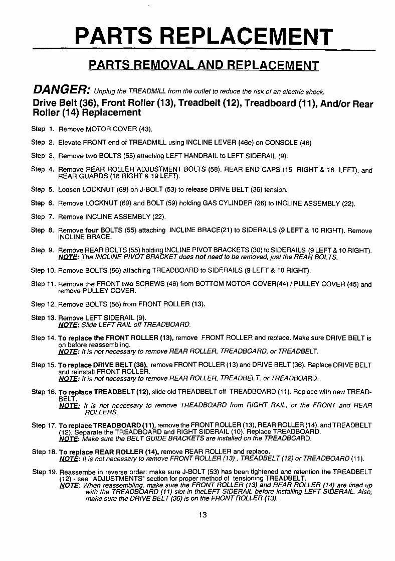
PARTS REPLACEMENTPARTS REMOVAL AND REPLACEMENT
DANGER: Unplugthe TREADMILL from the outlet to reduce the risk of an electric shock.
Drive Belt (36), Front Roller (13), Treadbelt (12), Treadboard (11), And/or RearRoller (14) Replacement
Step 1.
Step 2.
Step 3.
Step 4.
Step 5.
Step 6.
Step 7.
Step 8.
Remove MOTOR COVER (43).
Elevate FRONT end of TREADMILL using INCLINE LEVER (46e) on CONSOLE (46)
Remove two BOLTS (55) attaching LEFT HANDRAIL to LEFT SIDERAIL (9).
Remove REAR ROLLER ADJUSTMENT BOLTS (58), REAR END CAPS (15 RIGHT & 16 LEFT), andREAR GUARDS (18 RIGHT & 19 LEFT).
Loosen LOCKNUT (69) on J-BOLT (53) to release DRIVE BELT (36) tension.
Remove LOCKNUT (69) and BOLT (59) holding GAS CYLINDER (26) to INCLINE ASSEMBLY (22).
Remove INCLINE ASSEMBLY (22).
Remove four BOLTS (55) attaching INCLINE BRACE(21) to SIDERAILS (9 LEFT & 10 RIGHT). RemoveINCLINE BRACE.
Step 9.
Step 10.
Step 11.
Remove REAR BOLTS (55) holding INCLINE PIVOT BRACKETS (30) to SIDERAILS (9 LEFT & 10 RIGHT).NOTE: The INCLINE PIVOT BRACKET does not need to be removed, just the REAR BOLTS.
Remove BOLTS (56) attaching TREADBOARD to SIDERAILS (9 LEFT & 10 RIGHT).
Remove the FRONT two SCREWS (46) from BOTTOM MOTOR COVER(44) / PULLEY COVER (45) andremove PULLEY COVER.
Step 12. Remove BOLTS (56) from FRONT ROLLER (13).
Step 13. Remove LEFT SIDERAIL (9)._LO_TJ_:Slide LEFT RAIL off TREADBOARD.
Step 14. To replace the FRONT ROLLER (13), remove FRONT ROLLER and replace. Make sure DRIVE BELT ison before reassembling.JY_Q.T_E:It is not necessary to remove REAR ROLLER, TREADBOARD, or TREADBELT.
Step 15. To replace DRIVE BELT (36), remove FRONT ROLLER (13) and DRIVE BELT (36). Replace DRIVE BELTand reinstall FRONT ROLLER.blO_T_.E:It is not necessary to remove REAR ROLLER, TREADBEL T, or TREADBOARD.
Step 16. To replace TREADBELT (12), slide old TREADBELT off TREADBOARD (11). Replace with new TREAD-BELT.
It is not necessary to remove TREADBOARD from RIGHT RAIL, or the FRONT and REARROLLERS.
Step 17. To replace TREADBOARD (11), remove the FRONT ROLLER (13), REAR ROLLER (14), and TREADBELT(12). Separate the TREADBOARD and RIGHT SIDERAIL (10). Replace TREADBOARD.NOTE: Make sure the BELT GUIDE BRACKETS are installed on the TREADBOARD.
Step 18. To replace REAR ROLLER (14), remove REAR ROLLER and replace.]Y..O_.T_:It is not necessary to remove FRONT ROLLER (13), TREADBEL T (12) or TREADBOARD (11).
Step 19. Reassembe in reverse order: make sure J-BOLT (53) has been tightened and retention the TREADBELT(12) - see "ADJUSTMENTS" section for proper method of tensioning TREADBELT.bL(2T_E:When reassembling, make sure the FRONT ROLLER (13) and REAR ROLLER (14) are fined up
with the TREADBOARD (11) slot in theLEFT S/DERAIL before installing LEFT S/DERAIL. Also,make sure the DRIVE BELT (36) is on the FRONT ROLLER (13).
13
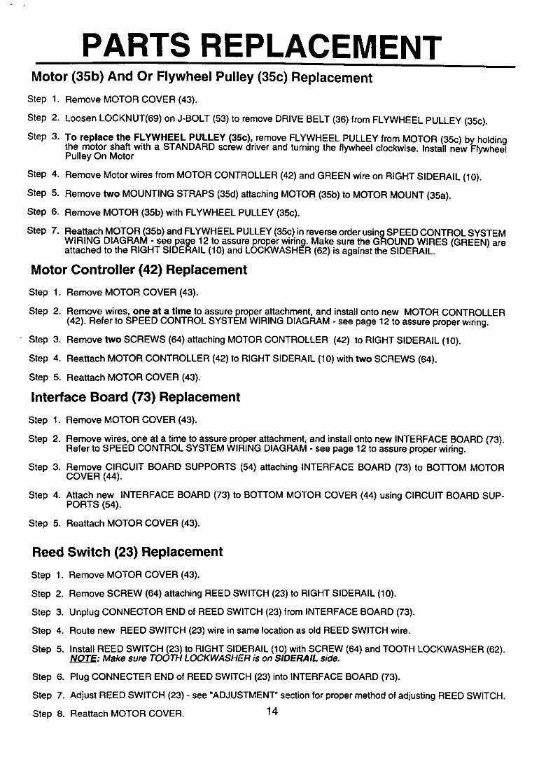
PARTS REPLACEMENTMotor (35b) And Or Flywheel Pulley (35c) Replacement
Step 1. Remove MOTOR COVER (43).
Step 2. Loosen LOCKNUT(69) on J-BOLT (53) to remove DRIVE BELT (36) from FLYWHEEL PULLEY (35c).
Step 3. To replace the FLYWHEEL PULLEY (35c), remove FLYWHEEL PULLEY from MOTOR (35c) by holdingthe motor shaft with a STANDARD screw driver and turning the flywheel clockwise. Install new FlywheelPulley On Motor
Step 4. Remove Motor wires from MOTOR CONTROLLER (42) and GREEN wire on RIGHT SIDERAIL (10).
Step 5. Remove two MOUNTING STRAPS (35d) attaching MOTOR (35b) to MOTOR MOUNT (35a).
Step 6. Remove MOTOR (35b) with FLYWHEEL PULLEY (35c).
Step 7. Reattach MOTOR (35b) and FLYWHEEL PULLEY (35c) in reverse order usingSPEED CONTROL SYSTEMWIRING DIAGRAM - see page 12 to assure proper wiring. Make sure the GROUND WIRES (GREEN) areattached to the RIGHT SIDERAIL (10) and LOCKWASHER (62) is against the SIDERAIL.
Motor Controller (42) Replacement
Step 1. Remove MOTOR COVER (43).
Step 2. Remove wires, one at a time to assure proper attachment, and install onto new MOTOR CONTROLLER(42). Refer to SPEED CONTROL SYSTEM WIRING DIAGRAM - see page 12 to assure proper wiring.
Step 3. Remove two SCREWS (64) attaching MOTOR CONTROLLER (42) to RIGHT SIDERAIL (10).
Step 4. Reattach MOTOR CONTROLLER (42) to RIGHT SIDERAIL (10) with two SCREWS (64).
Step 5. Reattach MOTOR COVER (43).
Interface Board (73) Replacement
Step 1. Remove MOTOR COVER (43).
Step 2. Remove wires, one at a time to assure proper attachment, and install onto new INTERFACE BOARD (73).Refer to SPEED CONTROL SYSTEM WIRING DIAGRAM - see page 12 to assure proper wiring.
Step 3. Remove CIRCUIT BOARD SUPPORTS (54) attaching INTERFACE BOARD (73) to BO]-rOM MOTORCOVER (44).
Step 4. Attach new INTERFACE BOARD (73) to BOTTOM MOTOR COVER (44) using CIRCUIT BOARD SUP-PORTS (54).
Step 5. Reattach MOTOR COVER (43).
Reed Switch (23) Replacement
Step 1.
Step 2.
Step 3.
Step 4.
Step 5.
Step 6.
Step 7.
Step 8.
Remove MOTOR COVER (43).
Remove SCREW (64) attaching REED SWITCH (23) to RIGHT SIDERAIL (10).
Unplug CONNECTOR END of REED SWITCH (23) from INTERFACE BOARD (73).
Route new REED SWITCH (23) wire in same location as old REED SWITCH wire.
Install REED SWITCH (23) to RIGHT SIDERAIL (10) with SCREW (64) and TOOTH LOCKWASHER (62).NOTE: Make sure TOOTH LOCKWASHER is on SIDERAIL side.
Plug CONNECTER END of REED SWITCH (23) into INTERFACE BOARD (73).
Adjust REED SWITCH (23) - see "ADJUSTMENT" section for proper method of adjusting REED SWITCH.
Reattach MOTOR COVER. 14

PARTS REPLACEMENTReset Switch (33) Replacement
Step 1. Remove MOTOR COVER (43).
Step 2. Remove wires from RESET SWITCH (33), one at a time to ensure proper attachment and install on newRESET SWITCH. Refer to SPEED CONTROL SYSTEM WIRING DIAGRAM on page 12 if necessary.
Step 3. Remove RESET SWITCH (33) from POWER CORD BRACKET (31).
Step 4. Reinsert RESET SWITCH (33) into POWER CORD BRACKET (31) and attach MOTOR COVER (43).
Console (46), Fitness Computer (46a), And/Or Power Switch Replacement
Step 1.
Step 2.
Step 3.
Step 4.
Step 5.
Step 6.
Remove CONSOLE attaching SCREWS (63).
Slip CONSOLE (46) out of CONSOLE TUBE (40).
Remove four SCREWS(46o) and one SCREW (46m) attaching FITNESS COMPUTER (46a) to CONSOLEBOTTOM (46b).
To replace FITNESS COMPUTER (46a), unplug FITNESS COMPUTER (46a) from WIRING HARNESS(46g) and plug in new FITNESS COMPUTER.NOTE: Rep/ace any monitor casing needed.
To replace POWER SWITCH (46k), remove wires from POWER SWITCH and attaching SCREW (461),snap POWER SWITCH out of the CONSOLE BOI-rOM (46b) and replace with new POWER SWITCH.
Reassembly in reverse order - see SPEED CONTROL SYSTEM WIRING DIAGRAM if necessary.
Wiring Harness (46g) Replacement
Step 1.
Step 2.
Step 3.
Step 4.
Step 5.
Step 6.
Step 7.
Step 8.
Step 9.
Step 10.
Step 11.
Step 12.
Step 13.
Remove MOTOR COVER (43).
Remove CONSOLE (46) - see CONSOLEAND/OR POWER SWITCH REPLACEMENT.NOTE: Steps 2 through 6 required for UPPER WIRING HARNESS replacement.
Remove BLACK wires from INTERFACE BOARD (73).
Remove BROWN wire from RESET SWITCH (31).
Remove LARGE CONNECTOR from INTERFACE BOARD(73),
Pull UPPER WIRING HARNESS (64g) from CONSOLE TUBE (40).
Remove SMALL CONNECTOR from INTERFACE BOARD (73).Steps 7 through 12 required for LOWER WIRING HARNESS replacement.
Remove GRAY and BLUE wire from MOTOR CONTROLLER (42).
Remove REED SWITCH (23) - see REED SWITCH REPLACEMENT.
Remove WHITE wires from INTERFACE BOARD (73).
Remove WHITE wire from MOTOR CONTROLLER (42).
Remove LOWER WIRING HARNESS.
Replace WIRING HARNESSES and reinstall in reverse order. Refer to SPEED CONTROL SYSTEMWIRING DIAGRAM to assure proper wiring.
15

PARTS REPLACEMENTIncline Lever (46e) Replacement
Step 1. Remove two SCREWS (63) at top of CONSOLE TUBE (40).
Step 2. Remove one SCREW (460) on lower rear side of CONSOLE BOTTOM (46b).
Step 3. Pull CONSOLE (46) from CONSOLE TUBE (40) and remove two SCREWS (46n) and remove LOWERCONTROL PANEL (46d) from CONSOLE BOTTOM (46b).
Step 4. Reinsert CONSOLE (46) into CONSOLE TUBE (40) for convenience.
Step 5. Remove two SCREWS (46n) attaching INCLINE BRACKET (46f) to back side of LOWER CONTROL PANEL(46d).
Step 6. Remove INCLINE LEVER (46e) from PIVOT SLOTS in back side of LOWER CONTROL PANEL (46d).
Step 7. Detach INCLINE LEVER (46e) from INCLINE CABLE (46j) by sliding CABLE END of INCLINE CABLE intoupper hole in INCLINE LEVER and pulling through.
Step 8. Reassemble CONSOLE (46) using REPLACEMENT INCLINE LEVER (46e) by following steps 1 through 8in reverse order.
Gas Cylinder (26) Replacement
Step 1. Hold INNER CABLE of INCLINE CABLE (46j) at GAS CYLINDER (26) with pliers. Press down onACTIVATING LEVER and disconnect INNER CABLE from ACTIVATING LEVER.
Step 2. Pull OUTER CABLE of INCLINE CABLE (46j) straight up with pliers to disconnect INCLINE CABLE fromACTIVATING LEVER.
Step 3. Remove front BOLT (59) and LOCKNUT (69) attaching GAS CYLINDER (26) to INCLINE FRAME (22).
Step 4. Remove rear BOLT (60) and LOCKNUT (69) attaching GAS CYLINDER (26) to INCLINE BRACE (21).
Step 5. Replace GAS CYLINDER (26) in reverse order.
END OF THREADED SHAFT TOBE FLUSH WITH FLAT SURFACEOF ACTUATING LEVER AS
SHOWN. INCLINEI o _ ABL
_E 46J
INNERCABLE
OUTERCABLE
ACTUATINGLEVER
PIVOTBRACKET
GAS CYLINDERASSEMBLY
16
ADJUSTMENTS
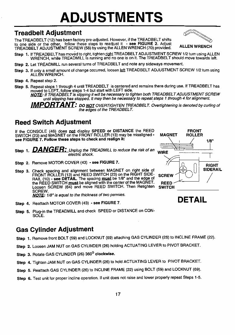
Treadbelt AdjustmentThe TREADBELT (12) has been factory pre-adjusted. However, ifthe TREADBELT shiftsto one side or the other, follow these steps to readjust it - see FIGURE 2. AdjustTREADBELT ADJUSTMENT SCREW (56) by usingthe ALLEN WRENCH (70) provided. ALLEN WRENCH
Step 1. If TREADBELT has moved to right,tighten rightTREADBELT ADJUSTMENT SCREW 1/2 turn usingALLENWRENCH, while TREADMILL is running and no one is on it. The TREADBELT should move towards left.
Step 2. Let TREADMILL run several turns of TREADBELT and note any sideways movement.
Step 3. If only a small amount of change occurred, loosen left TREADBELT ADJUSTMENT SCREW 1/2 turn usingALLEN WRENCH.
Step 4. Repeat step 2.
Step 5. Repeat steps 1 through 4 until TREADBELT is centered and remains there during use. If TREADBELT hasmoved to LEFT, follow steps 1-4 but start with LEFT side.NOTE: ff TREADBEL T is slipping it will be necessary to tighten both TREADBEL T ADJUSTMENT SCREW
until slipping has stopped. It may then be necessary to repeat steps 1 through 4 for alignment.
_D_L_L_'. DO NOT OVERTIGHTEN TREADBEL 7".Overtightening is denoted by curling ofthe edges of the TREADBEL T.
Reed Switch AdjustmentIf the CONSOLE (46) does not display SPEED or DISTANCE the REEDSWITCH (23) and MAGNET on the FRONT ROLLER (13) may be misaligned -see FIGURE 7. Follow these steps to check and realign it:
Step 1. _L__Unplug the TREADMILL to reduce the risk of anelectric shock.
Step 2,
Step 3.
Step 4.
Step 5.
Remove MOTOR COVER (43) - see FIGURE 7.
Check spacing and alignment between MAGNET on right side ofFRONT ROLLER (13) and REED SWITCH (23) on the RIGHT SIDE-RAIL (10) - see DETAIL. The spacing must be 1/8" and the edge ofthe REED SWITCH must be aligned with the center of the MAGNET.Loosen SCREW (64) and move REED SWITCH. Then RetightenSCREW.NOTE: 1/8" is equal to the thickness of two pennies.
Reattach MOTOR COVER (43) - see FIGURE 7.
Plug-in the TREADMILL and check SPEED or DISTANCE on CON-SOLE.
FRONTMAGNET ROLLER
/
WIRE
0REED/J _----
SWITCH
DETAIL
118"
IF
RIGHTSlDERAIL
/
Gas Cylinder AdjustmentStep 1. Remove front BOLT (59) and LOCKNUT (69) attaching GAS CYLINDER (26) to INCLINE FRAME (22).
Step 2. Loosen JAM NUT on GAS CYLINDER (26) holding ACTUATING LEVER to PIVOT BRACKET.
Step 3. Rotate GAS CYLINDER (26) 360 ° clockwise.
Step 4. Tighten JAM NUT on GAS CYLINDER (26) to hold ACTUATING LEVER to PIVOT BRACKET.
Step 5. Reattach GAS CYLINDER (26) to INCLINE FRAME (22) using BOLT (59) and LOCKNUT (69).
Step 6. Test unit for proper incline operation. If unit does not raise and lower properly repeat Steps 1-5.
17
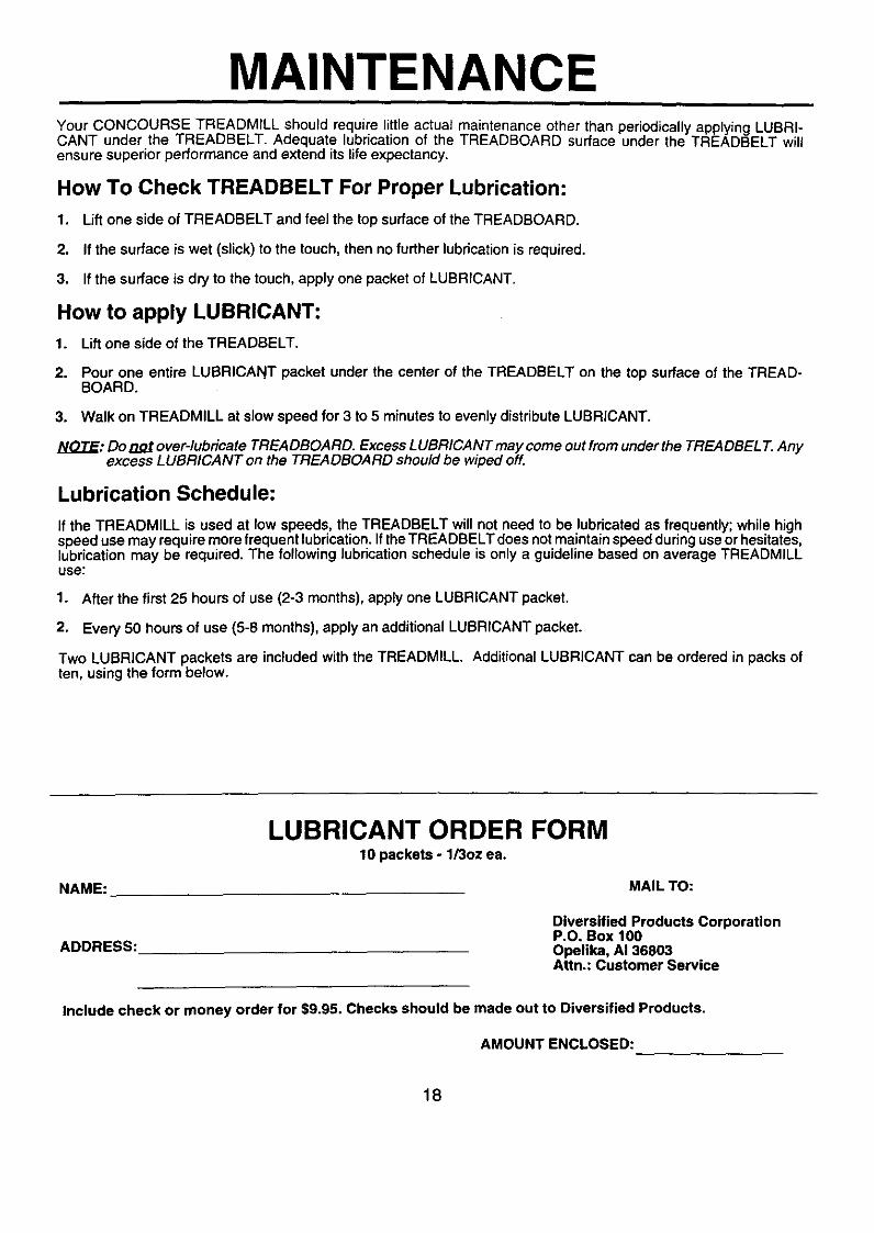
MAINTENANCEYour CONCOURSE TREADMILL should require little actual maintenance other than periodically applying LUBRI-CANT under the TREADBELT. Adequate lubrication of the TREADBOARD surface under the TREADBELT willensure superior performance and extend its life expectancy.
How To Check TREADBELT For Proper Lubrication:
1. Lift one side of TREADBELT and feel the top surface of the TREADBOARD.
2. If the surface is wet (slick) to the touch, then no further lubrication is required.
3. If the surface is dry to the touch, apply one packet of LUBRICANT.
How to apply LUBRICANT:
1. Lift one side of the TREADBELT.
2. Pour one entire LUBRICANT packet under the center of the TREADBELT on the top surface of the TREAD-BOARD.
3. Walk on TREADMILL at slow speed for 3 to 5 minutes to evenly distribute LUBRICANT.
NOTE: Do not over-lubricate TREADBOARD. Excess LUBRICANT may come out from underthe TREADBEL T.Anyexcess LUBRICANT on the TREADBOARD should be wiped off.
Lubrication Schedule:
If the TREADMILL is used at low speeds, the TREADBELT will not need to be lubricated as frequently; while highspeed use may require more frequent lubrication. If the TREADBELT does not maintain speed during use or hesitates,lubrication may be required. The following lubrication schedule is only a guideline based on average TREADMILLuse:
1. After the first 25 hours of use (2-3 months), apply one LUBRICANT packet.
2. Every 50 hours of use (5-8 months), apply an additional LUBRICANT packet.
Two LUBRICANT packets are included with the TREADMILL. Additional LUBRICANT can be ordered in packs often, using the form below.
LUBRICANT ORDER FORM10 packets - 1/3oz ea.
NAME: MAIL TO:
ADDRESS:
Diversified Products CorporationP.O. Box 100Openka, AI 36803Attn.: Customer Service
Include check or money order for $9.95. Checks should be made out to Diversified Products.
AMOUNT ENCLOSED:
18

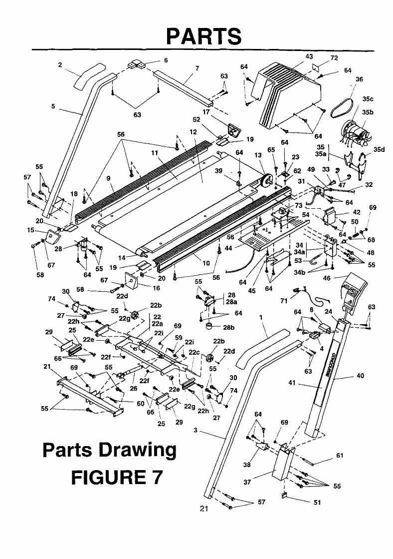
PARTSReplacement Parts List
12345
678910
1112131415
1617181920
212222a22b22c
22d22e22f
22i23242526
272828a28b
29
3031323334
34a34b
3535a35b
0404320004043500304642163129411638375316
0916930030464516312942163402691034026810
3937850009172300393937003938620009168800
0916890009169000091691000917020031292710
3835681639405300383738160907660031184500
2501890039152200250146003402991021027700
2502600037046100624441003402781039388300
3915220039393800383587160206400031299710
3129961631291816393689003702450039379900
3129251020016000393793003835651037041200
HandrailHandrail Bracket
Irail
Elbow ConnectorFront HandrailFront Handrail BracketLeft Siderail.Right Siderail
TreadboardTread BeltFront RollerRear RollerLeft Rear End Cap
Right Rear End CapLeft Front End CapLeft Rear GuardRight Rear & Left Front GuardSQuareWasher
Incline BraceIncline (Assembly)Incline FrameWheelRod
5/16" PushnutRoller5/16" LocknutIncline Rail#10 x 5/8" Long Machine Screw
t10 Capnut:leed SwitchOperation DecalIncline RailGas Cylinder w/Pivot Bracket
=loller=oot (Assembly)=ootFoot CapSpacer Plate
Incline Pivot BracketPower Cord BracketPower CordReset Switch 10 ampMotor Mount Bracket (Assembly)
Motor Mount Bracket#10 x 1/2" Sheet Metal ScrewsMotor / Motor Mount (Assembly)Motor MountMotor
11111
11111
11111
11122
11121
22224
41121
22222
21111
12111
19
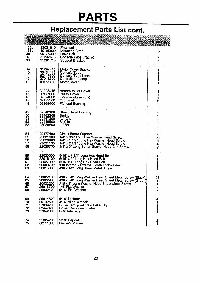
PARTSReplacement Parts List cont.
35c35d
363738
3940414243
4445464748
495O515253
5455565758
596O616263
6465666768
6970717273
7475
3302101039195600091753003129261631291710
3129241030464116624476003704320009165100
3129541609177200393940000917950009169400
3704010029452200294472002944980023020800
0917740023021000230209002302110022026700
2202000022018100220273002600970020016000
2002210020022900200222002601870026000400
2501460029192500370397006244740037042800
2502420060111600
FlywheelMounting StrapDrive BeltConsole Tube BracketSupport Bracket
BracketConsole TubeConsole Tube LabelController 10 ampMotor Cover
uottom Motor (..;overPulley CoverConsole (Assembly)GrommetFlanged Bushing
Strain Relief BushingSpdng"U" ClipS" Clip"J" Bolt"
Circuit Board Support1/4" x 3/4" Long Flex Washer Head Screw1/4" x 1 1/2" Long Hex Washer Head Screw1/4" x 2 112"Long Hex Washer Head Screw1/4" x 3" Long Button Socket Head Cap Screw
5/16" x 1 1/4" Long Hex Head Bolt5/16. x 2_ Long Hex Head Bolt5/16 x 4 Long Hex Head Bolt#10 Internal / External Tooth Lockwasher#10 x 1/2" Long Sheet Metal Screw
#10 x 5/8" Long Washer Head Sheet Metal Screw (Black)#10 x 5/8" Long Washer Head Sheet Metal Screw (Green#10 x 1" Long Washer Head Sheet Metal Screw1/4 Flat Washer5/16" Flat Washer
5116" Locknut3116" Allen WrenchPulse Eamlip w/Strain Relief ClipPower Disconnect LabelPCB Interface
5/16" CapnutOwner's Manual
12111
11111
11121
11111
422842
11118
281422
41111
21
20
57
55
2
PARTS7
63
64
43 72
s4
-/
63 1752
1264
19 6465 35
13 23 35a
49
36
35c
35d
64
4269//
58
29
55
25
22e
22f --_
69 55
22f26
22i 22b
I 55
3O
22e
45
66 i25 29
'\
2764
Parts DrawingFIGURE 7
21
34b
71
64 241
63
41
69
61
J 55
48
55
63
4O

PARTS
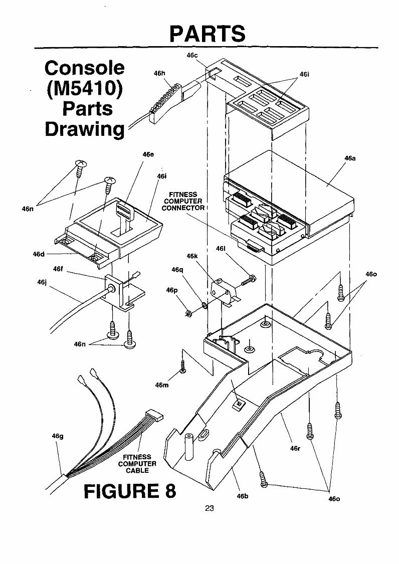
Console (M5410)Replacement Parts List
4646a46b46c46d
46e46f
46i
46146m46n
46046p46q46r
3939400037046200091703000917440009174800
0914610009145600393941003938000062445600
29452018 _37036400210266002102740020022100
2O020000250228002601300062443300
; Console (Assembly)Fitness Computer (M5410)
! Console BottomUpper Control PanelLower Control Panel -
Incline LeverIncline BracketWiring HarnessPower Key w/Cord & Belt Clip (Assembly)Control Panel Decal Sheet
Incline CableOn/Off Switch#4 x 7/8" Long Hex Washer Head Machine Screw#4 x 3/8" Long Machine Screw#10 x 5/8 Long Washer Head Sheet Metal Screw
#8 x 1/2" Long Sheet Metal Screw#4 Nut#4 Internal / External Tooth Lock WasherTrouble-Shooting Label
11111
11111
11114
5111
22
46n
46d "
46j
PARTS
Console(M5410)
PartsDrawing
46f
46n
46h
46e
46c
46i
FITNESSCOMPUTER
CONNECTOR I
46146k
46q _
46p
46i
46a
460
46g
FITNESSCOMPUTER
CABLE
FIGURE 8 46b
23460

PARTS
REPLACEMENT PARTS
For answers to questions not covered in this service manual, please contact our customer service! department at the following address or telephone number.
In the United States, call:
1-800-633-5730or write to:
Diversified Products CorporationP.O. Box 100Opelika, AL 36801Attn.: Customer Service - Parts
24