Embed Size (px)
Citation preview

MAESTRO: Methods and Advanced Equipment for Simulation
and Treatment in Radio-Oncology
Jean Barthe, Régis Hugon, Jean-Philippe Nicolaï
DRT/LIST, CEA, Saclay, 91191 Gif-sur-Yvette Cedex, France
Abstract
The integrated project MAESTRO (Methods and Advanced Equipment for Simulation and
Treatment in Radio-Oncology) under contract with the European Commission in life sciences
FP6 (LSHC-CT-2004-503564), concerns innovative research to develop and validate in clinical
conditions, advanced methods and equipment needed in cancer treatment for new modalities in
high-conformal external radiotherapy using electrons, photons and protons beams of high
energy.
Keywords : Radiation therapy, Treatment Planning Software, X-ray imaging, Dose
measurement
1. Introduction
1.1. Context
At the beginning of the third millennium, one European citizen out of three will have to deal
with a cancer episode in the course of his/her life. Worldwide, the estimated number of new
cancer cases each year is expected to rise from 10 million in 2000 to 15 million by 2020. Cancer
is currently the cause of 12% of all deaths worldwide. Within the European union, over 1.5
million new cancer cases are diagnosed every year and over 920,000 people die of cancer with
the two leading causes of cancer in Europe being the breast and prostate. Therefore, combating
cancer is a major societal and economical issue for Europe. To face these new challenges, strong
mobilisation among the scientific community and industrial manufacturers is needed [1].
Today three main approaches to treat cancer are used: the surgical removal of the tumour and
the adjoining tissue, chemotherapy, and radiotherapy. In many cases immuno-therapy is used
as a complementary or palliative treatment. Among them radiotherapy remains a major
technique to treat cancer. More than a half of all cancer patients are now treated by radiation
therapy (RT); thanks to the technical progress made with irradiation equipment in the last 10
years.
For external radiation therapy, for instance, high-energy photon or electron beams are most
widely used and mainly produced by linear accelerators, while a very limited number of proton
synchrotrons or cyclotrons are typically used for the treatment of cancers close to vulnerable
organs, such as the eyes and the optical and auditory nerves, or the spinal cord.
To do this, new technologies in the field of dose calculation and dose measurement tools are
developed and linked to the emerging Intensity-Modulated Radiation Therapy (IMRT)
technique and proton therapy, which are the main elements of the project [2].
1.2. Structure of the project
The project is organised into six work-packages (WP), among which three are dedicated to
scientific development: improving conformation, imaging and measurement of dose delivered
to the target (tumorous tissues) whatever its shape in order to spare the surrounding tissues:
(a) Adaptive radiation delivery, tracking and control for radiotherapy including proton
therapy.
(b) Advanced software for image processing, and fast and accurate treatment planning
system (TPS) using Monte Carlo codes.
(c) Sensors for dose evaluation: punctual dosimeters, two and three dimension dosimeters,
and imagers based on passive and electronic modes.
(d) Clinical requirements, protocols and validation including organs at risk assessment
studies.
(e) Clinical workshops, training and dissemination purposes to manufacturers.
(f) Technical and financial management. It is mainly assumed by the CEA team.
The hub is assumed by the 4th which proposes at first medical requirements, then experimental
protocols and, eventually, manages the corresponding testing controls.
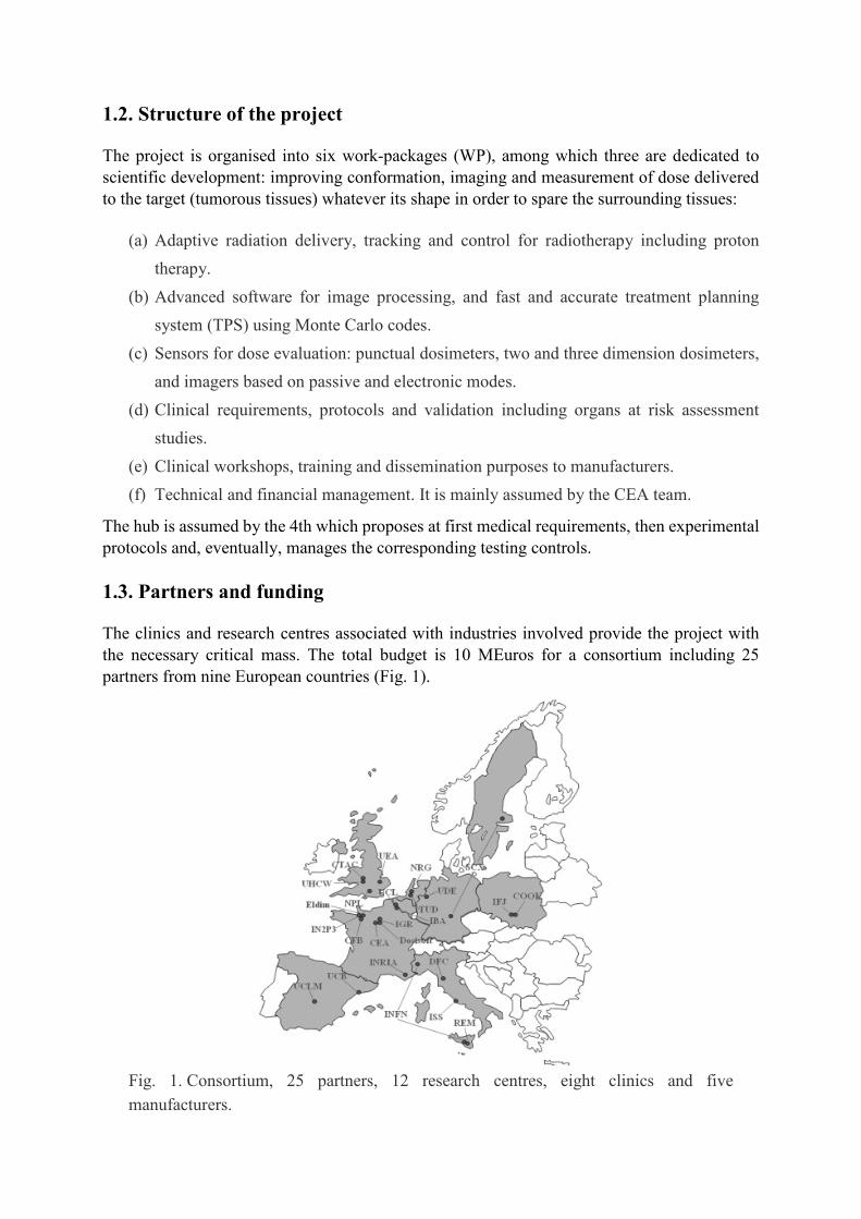
1.3. Partners and funding
The clinics and research centres associated with industries involved provide the project with
the necessary critical mass. The total budget is 10 MEuros for a consortium including 25
partners from nine European countries (Fig. 1).
Fig. 1. Consortium, 25 partners, 12 research centres, eight clinics and five
manufacturers.

1.4. List of partners and acronyms
The following acronyms are used for all documents with the European Union in order to specify
the identification of partners in the project. These acronyms have to be short and significant in
accordance with their use in the different member states. They are sorted following their
sequence inside MAESTRO (Methods and Advanced Equipment for Simulation and Treatment
in Radio-Oncology).
CEA: Commisariat à l’Energie Atomique, Saclay (France),
IBA: Ion Beam Applications SA, Louvain (Belgium),
TUD: Delft University of Technology (The Netherlands),
INFN: Istituto Nazionale di Fisica Nucleare, Catania, Torino (Italy),
Dosisoft: DOSISOFT S.A., Cachan (France),
IFJ: Instytut Fizyki Jadrowej, Krakov (Poland),
ELDIM: ELDIM SA., Caen (France),
NRG: Nuclear Research and Consultancy Group (NL),
DFC: Univ. di Firenze-Dipartimento Fisiopatologia Clinica (Italy),
REM: REM Radioterapia SRL, Catania (Italy),
ISS: Istituto Superiore di Sanita, Roma (Italy),
CTAC: Coventry University (UK),
NPL: National Physical Laboratory, Tedington (UK),
IGR: Institut Gustave Roussy, Villejuif (France),
IN2P3: Centre Nat. de la Recherche Scientifique, Caen (France),
CFB: Centre François Baclesse, Caen (France),
UDE: University of Duisburg Essen (Germany),
UEA: University of East Anglia, Norwitch (UK),
UCLM: Universidad de Castilla-La Mancha, Cuidad Real (Spain),
UHCW: University Hospitals Coventry and Warwickshire (UK),
COOK: Centre of Oncology—M. Skłodowska-Curie, Krakov (Poland),
INRIA: Inst. Nat. de Rech. Inf. et Aut., Sophia Antipolis (France),
UCB: Universitat of Barcelona (Spain),
SCX: Scanditronix-Wellhöfer, Upsala (Sweden) and Schwarzenbruck (Germany),
UCL: Université Catholique de Louvain (Belgium).
2. Adaptive radiation delivery
“Adaptive radiation delivery” means that patient-specific variations are taken into account in
real time during radiation delivery throughout a course of radiotherapy. In the following, studies
are listed that are in progress within the MAESTRO project in order to provide the required
technical infrastructure for adaptive radiation delivery.
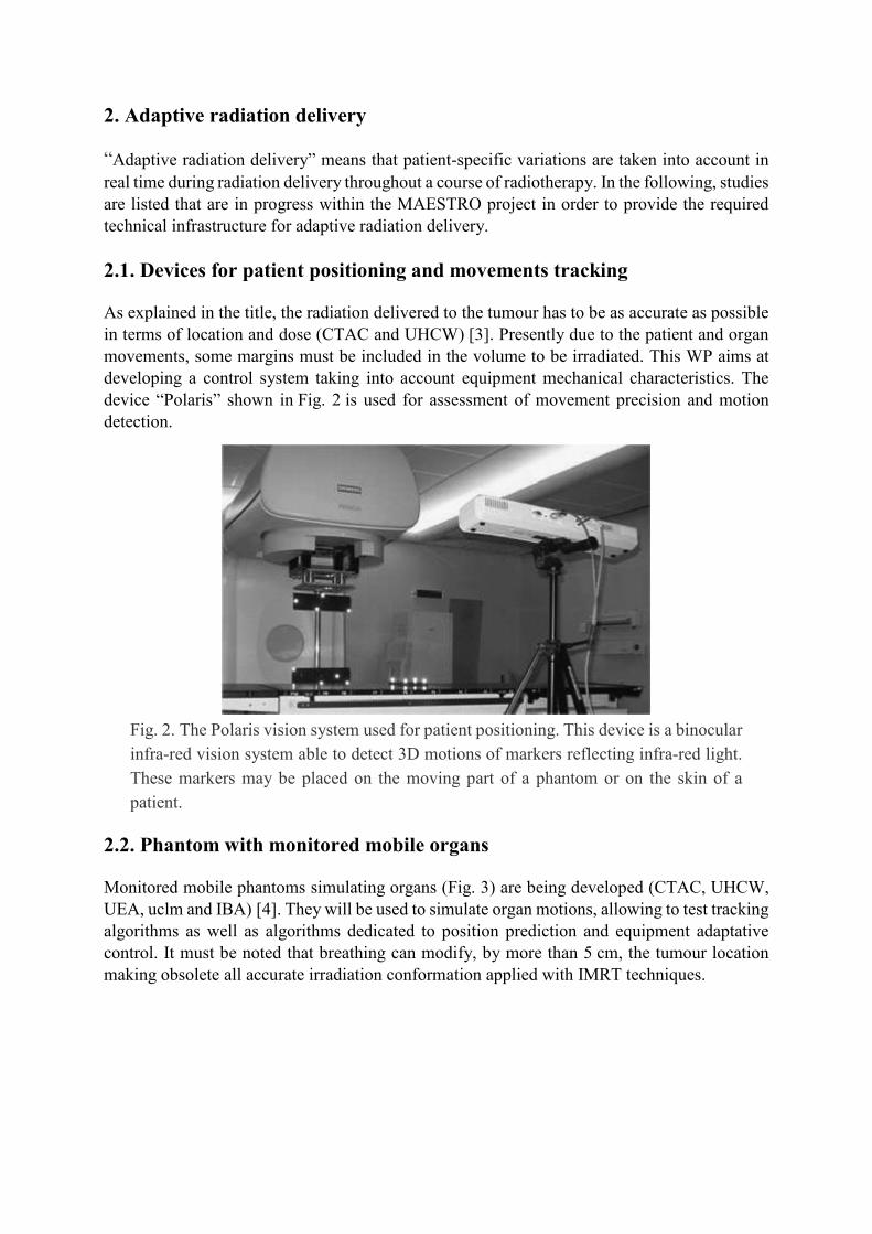
2.1. Devices for patient positioning and movements tracking
As explained in the title, the radiation delivered to the tumour has to be as accurate as possible
in terms of location and dose (CTAC and UHCW) [3]. Presently due to the patient and organ
movements, some margins must be included in the volume to be irradiated. This WP aims at
developing a control system taking into account equipment mechanical characteristics. The
device “Polaris” shown in Fig. 2 is used for assessment of movement precision and motion
detection.
Fig. 2. The Polaris vision system used for patient positioning. This device is a binocular
infra-red vision system able to detect 3D motions of markers reflecting infra-red light.
These markers may be placed on the moving part of a phantom or on the skin of a
patient.
2.2. Phantom with monitored mobile organs
Monitored mobile phantoms simulating organs (Fig. 3) are being developed (CTAC, UHCW,
UEA, uclm and IBA) [4]. They will be used to simulate organ motions, allowing to test tracking
algorithms as well as algorithms dedicated to position prediction and equipment adaptative
control. It must be noted that breathing can modify, by more than 5 cm, the tumour location
making obsolete all accurate irradiation conformation applied with IMRT techniques.

Fig. 3. Moving lungs phantom.
2.3. Development of organ tracking algorithms
Present studies concern the tracking of tumour motions in real time with fast image processing
techniques (CTAC, UEA, uclm) [5]. The algorithms under development are based on the use
of internal or external markers or on processing of marker-free images. Fig. 4 shows a thorax
movement derived from a training phase and subsequent breathing movement modelling.
Fig. 4. Pseudo periodical thorax movement. Such a signal is generated to make the lung
phantom to simulate lung motions.
2.4. Intensity Modulation Proton Therapy (IMPT)
This technique uses Pencil Beam Scanning (PBS) (IBA) [6]. Presently, mono-energetic protons
are spread and slowed down using absorbers. The PBS (Fig. 5) allows to transport the beam-
like electrons into a TV cathode tube, reducing the equipment size and increasing the accuracy
in terms of dose delivered and volume irradiated. A few proton-scanning systems are currently
being evaluated throughout the world, for example at the Massachusetts General Hospital in
Boston.

Fig. 5. IBA pencil beam scanning intensity modulation principle. Unlike large scattered
beams, a thin (“pencil”) proton beam is made to scan the target thanks to magnets.
2.5. Multi-modality imaging and Monte Carlo dose calculation software
(a) Software for virtual simulation including multi-modality image registration and organ
segmentation based on anatomical atlas (DOSISOFT and INRIA) [7]. The integration
of an anatomical atlas for an automatic segmentation of organs at risks (OAR) and an
expert system for the setup of the treatment provides major help to achieve segmentation
of organs, in particular by reducing time spent by medical doctors. In addition,
automatic atlas-based segmentation will better adapt IMRT to clinical conditions. Atlas
development concerns skull, head and neck, prostate, and pelvis organs. Fig. 6 shows a
3D digital radiography reconstruction.
Fig. 6. 3D digital radiography reconstruction.
(b) Software for 3D dose calculation based on the Monte Carlo code PENELOPE
(DOSISOFT and UCB). Presently dose calculations are performed by using numerical
methods based on a presupposed knowledge of dose distribution, which leads to
deviations from the true distribution, in particular in organs such as the lung (Fig. 7).
This method needs to be calibrated with preliminary experiments. Their accuracy may
not be sufficient and depends on the complexity of tissues surrounding the tumour.
Monte Carlo codes, where all known physics processes can be included, are up to now
the best solution for complex problems. On the other side this technique is very time

consuming. The challenge, almost reached at this time, is to develop a set of codes based
on PENELOPE [8] able to calculate the dose distribution in less than 10 min with a
voxel resolution close to 1 mm for complex localisation.
Fig. 7. Example of deformation of lungs isodoses.
3. Dosimeters and 2D/3D imagers
This WP includes eight sub-WP and 12 partners. Three kinds of dosimeters and imagers are
under study: point, 2D and 3D dosimeters. Three of them are passive, i.e. based on solid-state
transformation (thermoluminescence (TL) and Fricke gel needing a post-irradiation reading
process), others are active, i.e. electronic (2D: silicon, GEM, pixel chamber and 3D:
scintillation imagers).
3.1. Diamond dosimeters
Two technologies are used, chemical vapour deposition (CVD) diamond ionisation chamber
(CEA, IFJ, INFN, SCX) and TL dosimeters (CEA, IFJ). CEA produces CVD diamond, mostly
polycrystalline, in specific microwave reactors from methane gas. The WP focuses on growing
process and concomitant physical characteristics of detectors (such as linearity, stability,
reproducibility) [9]. Fig. 8 shows a TL detector and an ionisation chamber made of diamond.

Fig. 8. TL (on the right) and diamond ionisation chamber (on the left).
3.2. Sixteen-way remote optically stimulated luminescence (OSL) dosimeters
using optical fibres
The OSL technology allows on-line and delayed read-outs at the same time (CEA) [10]. The
sensitive head (reduced alumina) is fixed on an optical fibre allowing remote dose and dose rate
measurements. A laser light is used to excite the dosimeter allowing to collect the induced
fluorescence emitted by a PM tube. A prototype (Fig. 9) is being evaluated. A manufacturer has
been chosen for industrialisation.
Fig. 9. Remote OSL dosimeter and reader. On the front panel are, in a circular layout,
the optical fibre connexions.
3.3. Planar SI imager
The basic idea is to use a segmented SI module obtained from 4 in. monocrystal wafers (DFC,
INFN). A diode grid of 441 macro-pixels (2×2 mm2) is engraved on each wafer. The whole
portal dosimeter will be composed of a set of nine SI segmented modules (Fig. 10). Each set of
diode signals is read-out with a “tera-chip” circuit. The first laboratory results showed strong
radiation for more than 10 kGy. Characterisation [11] and realistic tests were started in a
hospital. (A complete presentation can be seen in the paper of Cinzia Talamonti published in
this same issue.)

Fig. 10. Open view of the current DFC 2D silicon imager. This device includes a single
6×6 cm2 detection module, while the final demonstrator will include nine of them.
3.4. 2D dose imager: Gas Electron Multiplier
The main objective of this study (TU-DELFT) is to use and adapt devices developed at CERN
for measurements in physics: a grid of holes manufactured on an insulator substrate (Fig. 11),
sandwiched between two metallic electrodes and inserted in a gas-filled case, serves as a 2D
electron beam amplifier when an appropriate voltage is applied. When radiation goes through
the local electric field of grid holes, the avalanche created produces UV–vis light. A CCD
camera, localised out of the radiation beam, integrates the light and rebuilds the dose map
image [12]. First results are very encouraging.
Fig. 11. Hole structure of the GEM plate. Each side of the plate serves as an electrode;
the potential between the two electrodes allows incoming electrons to create avalanche
and produce light. The plate is located inside a case in which electric field, perpendicular
to the case, is applied. This makes secondary electrons created by incident radiation to
go through the holes.

3.5. Pixelised ionisation chamber for IMPT and IMRT
A set of 1024 very small ionisation chambers are machined into an insulating equivalent tissue
plate and sandwiched between two metallic thin foils (SCX, INFN). Electric high voltage is
applied on the two sides. Ionisation chambers are independently connected to 1024 charge
amplifiers. A specific circuitry “tera-chip” has been developed. Of interest is the performance
in the ionisation regime which allows direct assessment of dose (Fig. 12). The functional
prototype has been tested in several clinics for IMRT verification [13] and a first version is now
commercialised under the trade mark “MatriXX”.
Fig. 12. Dosimetric image from the MatriXX imager.
3.6. TL large-area dose imager
LiF material is well known for its applications in dosimetry, good linearity with dose,
practically tissue equivalence and low sensitive to photon radiation energy. The objective is to
take over radiographic films which are time consuming (IFJ) [14]. For those large surface film
dosimeters, an adapted reader has to be developed. TL films are made of a mixture of LiF
powder and polymer with the correct granulometry able to support the reading temperature.
Such foils allow dose distribution measurement even for non-planar surfaces. The TL dose
signal is obtained by measurement with a CCD camera of the luminescence emitted by heating
during the reading phase (Fig. 13). Challenge is to obtain good contrast, low detection threshold
and surface uniformity. Results in progress are very promising.

Fig. 13. Dosimetric image from a large TL area imager.
3.7. 3D Fricke gel polymer dosimetry
IMRT is a very complex radiation delivery technique for which many controls have to be made
prior to treatment. In case of doubt, a gel Fricke phantom representative of the patient tumour
zone may be formed and irradiated using the TPS procedure in the same way as the patient. The
dose read-out [15] often performed using MRI in other fields is being developed within
MAESTRO on the base of visual tomography. Many difficulties linked to preparation of the
gel and ion diffusion have to be solved. Present results (ISS) are very promising. As an
example, Fig. 14 shows a picture of a pattern test highlighting the resolution obtained.
Fig. 14. Pattern test showing the resolution of the dosimetric gel polymer.

3.8. 3D plastic scintillator dosimetry
Up to now medical accelerator energy, dose and profile controls are very time consuming. Dose
control has to be performed at least once a day, profile and energy controls once a week. Such
controls are mostly performed using an ionisation chamber moving in a water tank or solid
water phantom. The 3D plastic scintillator would allow in one step to assess the complete data
in a short time (around 10 min) (IN2P3, ELDIM, CFB) [16]. The principle of the detector relies
on the linear scanning of a planar plastic scintillator perpendicularly to the 2D scintillator. The
intensity emitted in each point of the scintillator is measured on line by using a CCD camera
(Fig. 15). Some problems linked to Cherenkov effect and camera protection have to be
overcome. The first prototype is under test at CFB.
Fig. 15. Dosimetric image from the scintillation DOSIMAP system. The planar
scintillator has been laid out in a parallel to the beam, the figure shows the deapness
profile of the dose deposited.
4. Clinical issues
Validations are planned into three stages:
(a) Definition of the terms and conditions or requirements (all clinics). This subwork
package was first realised. It defines, for use under realistic medical conditions, most of
the requirements for tools developed in the project in technical work packages. For
adaptive radiation delivery, due to newness and system complexity, many questions will
be answered later.
(b) Assurance quality and experimental protocols (all clinics). This task deals with the
manner in which tests have to be made. Experimental protocols and procedures are
written in order to meet these requirements with a real assurance of quality.
(c) Pre-clinical and clinical validations of tools developed in MAESTRO (all clinics).
Results by medical practitioners obtained under previous protocols are collected and
treated in order to confirm both compliance with requirements and to give an experience
feedback to the developers. Fig. 16 shows the multi-purpose body phantom used for
pre-clinic qualification tests.
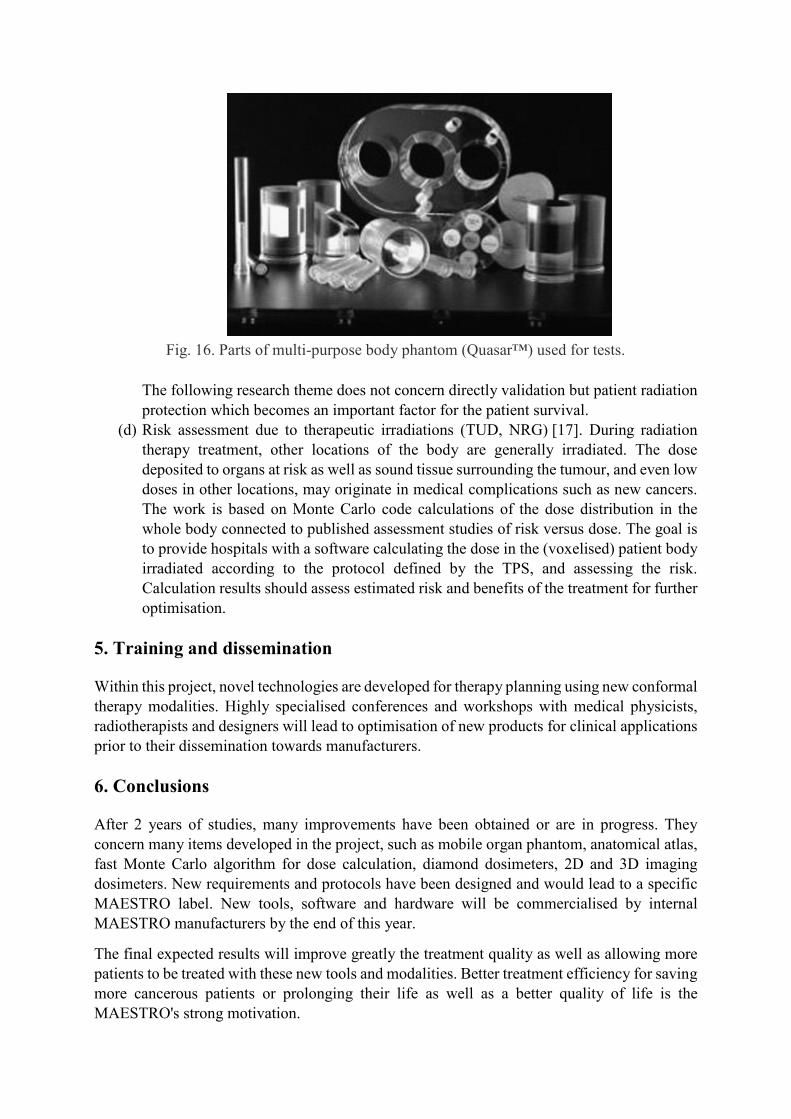
Fig. 16. Parts of multi-purpose body phantom (Quasar™) used for tests.
The following research theme does not concern directly validation but patient radiation
protection which becomes an important factor for the patient survival.
(d) Risk assessment due to therapeutic irradiations (TUD, NRG) [17]. During radiation
therapy treatment, other locations of the body are generally irradiated. The dose
deposited to organs at risk as well as sound tissue surrounding the tumour, and even low
doses in other locations, may originate in medical complications such as new cancers.
The work is based on Monte Carlo code calculations of the dose distribution in the
whole body connected to published assessment studies of risk versus dose. The goal is
to provide hospitals with a software calculating the dose in the (voxelised) patient body
irradiated according to the protocol defined by the TPS, and assessing the risk.
Calculation results should assess estimated risk and benefits of the treatment for further
optimisation.
5. Training and dissemination
Within this project, novel technologies are developed for therapy planning using new conformal
therapy modalities. Highly specialised conferences and workshops with medical physicists,
radiotherapists and designers will lead to optimisation of new products for clinical applications
prior to their dissemination towards manufacturers.
6. Conclusions
After 2 years of studies, many improvements have been obtained or are in progress. They
concern many items developed in the project, such as mobile organ phantom, anatomical atlas,
fast Monte Carlo algorithm for dose calculation, diamond dosimeters, 2D and 3D imaging
dosimeters. New requirements and protocols have been designed and would lead to a specific
MAESTRO label. New tools, software and hardware will be commercialised by internal
MAESTRO manufacturers by the end of this year.
The final expected results will improve greatly the treatment quality as well as allowing more
patients to be treated with these new tools and modalities. Better treatment efficiency for saving
more cancerous patients or prolonging their life as well as a better quality of life is the
MAESTRO's strong motivation.

MAESTRO's main achievements concerning the next generation of radiotherapy equipment
and services, improving the safety of patients and benefiting their health will be available over
the next years.
References.
[1] J. Barthe, J.P. Nicolai, MAESTRO Expression of Interest, European Union, June 2003.
[2] J.P. Nicolai, J. Barthe, MAESTRO Technical Annex I, Sixth Framework Programme
Proposal, European Union, March 2004.
[3] O.C.L. Haas, K.J. Burnham, J.A. Mills. Phys. Med. Biol., 43 (1998), p. 2179
[4] I. Land, J.A. Mills, O.C.L. Haas, A. Wilson, K. Burnham, Theoretical and experimental
geometric phantom accuracy for motion detection in adaptive radiotherapy, Strahlenther.
Onkol., Sondernr.1, Poster P10–77, 182, May 2006, p. 118.
[5] D. Putra, O.C.L. Haas, J. A. Mills, K.J. Burnham, Prediction of tumour motion using
interacting multiple model filter, in: Proceedings of the Third International Conference
MEDSIP 2006 Advances in Medical, Signal and Information Processing, Glasgow, 2006, p. 4.
[6] D. Prieels, B. Marchand, B. Bauvir, P. De Crock, G.S. Schmidt, G. Andre, S. Ternier, Y.
Jongen, in: AIP-Conf.-Proc. 576 (2001) 857.
[7] A. Isambert, F. Dhermain, A. Beaudre, G. Malandain, O. Commowick, J.C. Diaz,
M. Bidault, P.Y. Bondiau, J. Bourhis, M. Ricard, D. Lefkopoulos. J. Radiother. Oncol., 76
(Suppl. 2) (2005), p. S133
[8] F. Salvat, J.M. Fernández-Varea, J. Sempau, PENELOPE-2006: a code system for Monte
Carlo simulation of electron and photon transport, in: Workshop Proceedings Barcelona, Spain,
4–7 July 2006, Book of Proceedings Edited by OECD NEA as an User Manual No. 6222, 2006.
[9] M.J. Guerrero, D. Tromson, R. Barrett, R. Tucoulou Tachouères, P. Bergonzo, Phys. Stat.
Sol. (a), 201 (2004), p. 2529
[10] S. Magne, P. Ferdinand, Dosimétrie OSL à fibre optique, in: presented at Colloque OPTRO
2005, Ecole Polytechnique, Paris, 9–12 May 2005.
[11] S. Amerio, A. Boriano, F. Bourhaleb, R. Cirio, M. Donetti, A. Fidanzio, E. Garelli,
S. Giordanengo, E. Madon, F. Marchetto, U. Nastasi, C. Peroni, A. Piermattei, C.J. Sanz
Freire, A. Sardo, E. Trevisiol, Med. Phys., 31 (2) (2004), p. 414
[12] A. Simon, E. Seravalli, R. Kreuger, J. Hendrikse, E. Loeff, B.J.M. Heijmen, C.E.W. van-
Eijk, Scintillating triple GEM beam monitor for radiation therapy, in: IEEE-Nuclear-Science-
Symposium Conference Record IEEE Category No. 05CH37692C, 2006, p. 2770.
[13] I. Gomola, S. Giordanengo, S. Iliescu, R. Cirio, M. Donetti, F. Marchetto, C. Peroni,
M. Stasi, Radiother. Oncol., 76 (2005), p. 1573
[14] P. Bilski, P. Olko, M.P.R. Waligórski, Radiat. Meas., 38 (4–6) (2004), p. 833
[15] F. de Pasquale, A.M. Luciani, M. Pacilio, L. Guidoni, V. Viti, F. d’Errico, P. Barone,
G. Sebastiani, Radiat. Prot. Dosimetry, 99 (1–4) (2002), p. 363

[16] J.M. Fontbonne, Conception et réalisation d’un dosimètre à scintillation adapté à la
dosimétrie de faisceaux de rayonnements ionisants en radiothérapie, Thèse de l’Université de
Caen, 2002.
[17] A.G. Rijkeel, J. Zoetelief, C.P.J. Raaijmakers, S.C. Van Der Marck, W. Van Der Zee,
Radiat. Prot. Dosimetry, 118 (2006), p. 219