Embed Size (px)
Citation preview
1
MAGNAMAXDVR
DIGITAL VOLTAGE REGULATOR
TECHNICAL MANUAL
MODEL DVR 2000 AND DVR 2000C
2
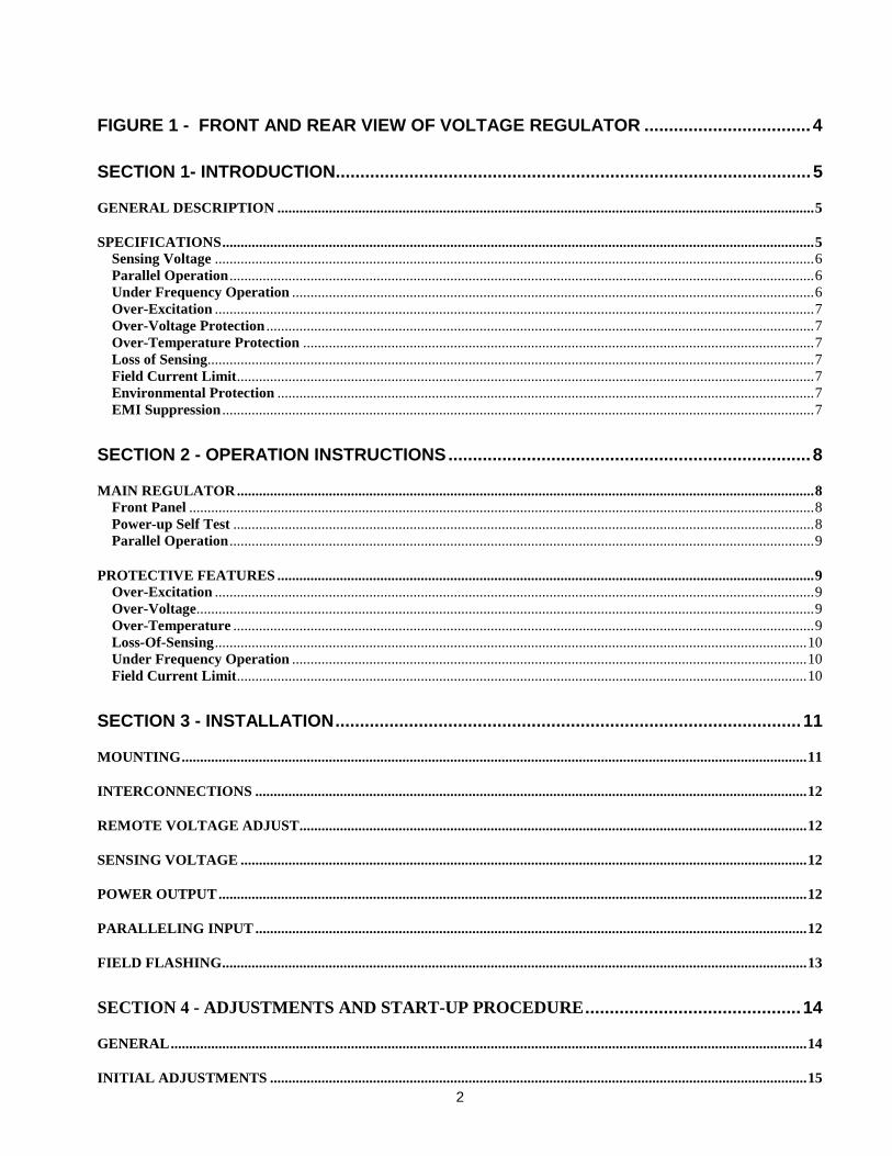
FIGURE 1 - FRONT AND REAR VIEW OF VOLTAGE REGULATOR ..................................4
SECTION 1- INTRODUCTION.................................................................................................5
GENERAL DESCRIPTION ..................................................................................................................................................5
SPECIFICATIONS.................................................................................................................................................................5Sensing Voltage ...................................................................................................................................................................6Parallel Operation ...............................................................................................................................................................6Under Frequency Operation ..............................................................................................................................................6Over-Excitation ...................................................................................................................................................................7Over-Voltage Protection .....................................................................................................................................................7Over-Temperature Protection ...........................................................................................................................................7Loss of Sensing.....................................................................................................................................................................7Field Current Limit.............................................................................................................................................................7Environmental Protection ..................................................................................................................................................7EMI Suppression .................................................................................................................................................................7
SECTION 2 - OPERATION INSTRUCTIONS..........................................................................8
MAIN REGULATOR.............................................................................................................................................................8Front Panel ..........................................................................................................................................................................8Power-up Self Test ..............................................................................................................................................................8Parallel Operation ...............................................................................................................................................................9
PROTECTIVE FEATURES ..................................................................................................................................................9Over-Excitation ...................................................................................................................................................................9Over-Voltage........................................................................................................................................................................9Over-Temperature ..............................................................................................................................................................9Loss-Of-Sensing.................................................................................................................................................................10Under Frequency Operation ............................................................................................................................................10Field Current Limit...........................................................................................................................................................10
SECTION 3 - INSTALLATION...............................................................................................11
MOUNTING..........................................................................................................................................................................11
INTERCONNECTIONS ......................................................................................................................................................12
REMOTE VOLTAGE ADJUST..........................................................................................................................................12
SENSING VOLTAGE ..........................................................................................................................................................12
POWER OUTPUT................................................................................................................................................................12
PARALLELING INPUT ......................................................................................................................................................12
FIELD FLASHING...............................................................................................................................................................13
SECTION 4 - ADJUSTMENTS AND START-UP PROCEDURE............................................14
GENERAL.............................................................................................................................................................................14
INITIAL ADJUSTMENTS ..................................................................................................................................................15
3
FINE VOLTAGE ADJUSTMENT......................................................................................................................................16
COARSE VOLTAGE ADJUSTMENT...............................................................................................................................16
REMOTE VOLTAGE ADJUSTMENT..............................................................................................................................16
STABILITY RANGE ADJUSTMENT ...............................................................................................................................17
UNDER FREQUENCY ADJUSTMENT............................................................................................................................18
DROOP ADJUSTMENT......................................................................................................................................................19
REACTIVE DIFFERENTIAL (CROSS CURRENT) ADJUSTMENT...........................................................................21
VAR/PF ADJUSTMENT......................................................................................................................................................21
SECTION 5 - TROUBLE SHOOTING....................................................................................23
Symptom ................................................................................................................................................................................23No voltage buildup ............................................................................................................................................................23Output Voltage Low..........................................................................................................................................................24Output Voltage High.........................................................................................................................................................24Generator does not respond as adjustments are made. .................................................................................................24Poor Voltage Regulation...................................................................................................................................................24Remote Voltage Control Operates Backwards. ..............................................................................................................24Remote Voltage Control functions in one direction only. ..............................................................................................24Generator Voltage Hunting..............................................................................................................................................24Under Frequency LED on. ...............................................................................................................................................25Over-excitation LED on....................................................................................................................................................25Field Limit LED on. ..........................................................................................................................................................25(Over-excitation LED on). ................................................................................................................................................25All LED's off but regulator working. ..............................................................................................................................26Long time for LED scan to be accomplished, .................................................................................................................26Voltage does not build up after engine is idled. ..............................................................................................................26Regulator fails immediately after replacement...............................................................................................................26
SECTION 7 - DRAWINGS .....................................................................................................27
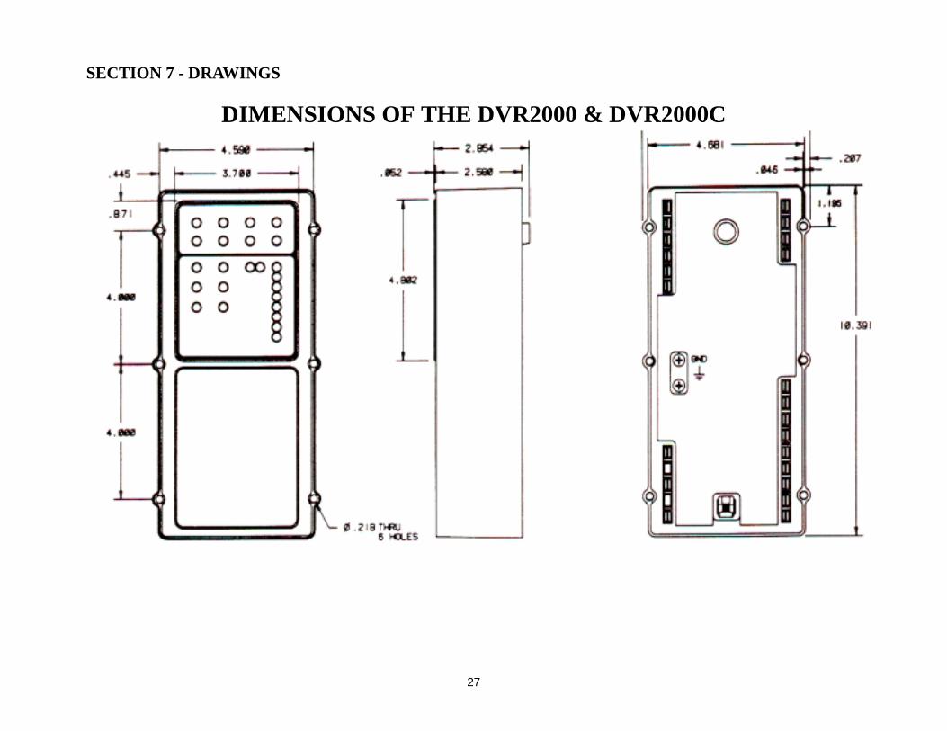
DIMENSIONS OF THE DVR2000 & DVR2000C.............................................................................................................27
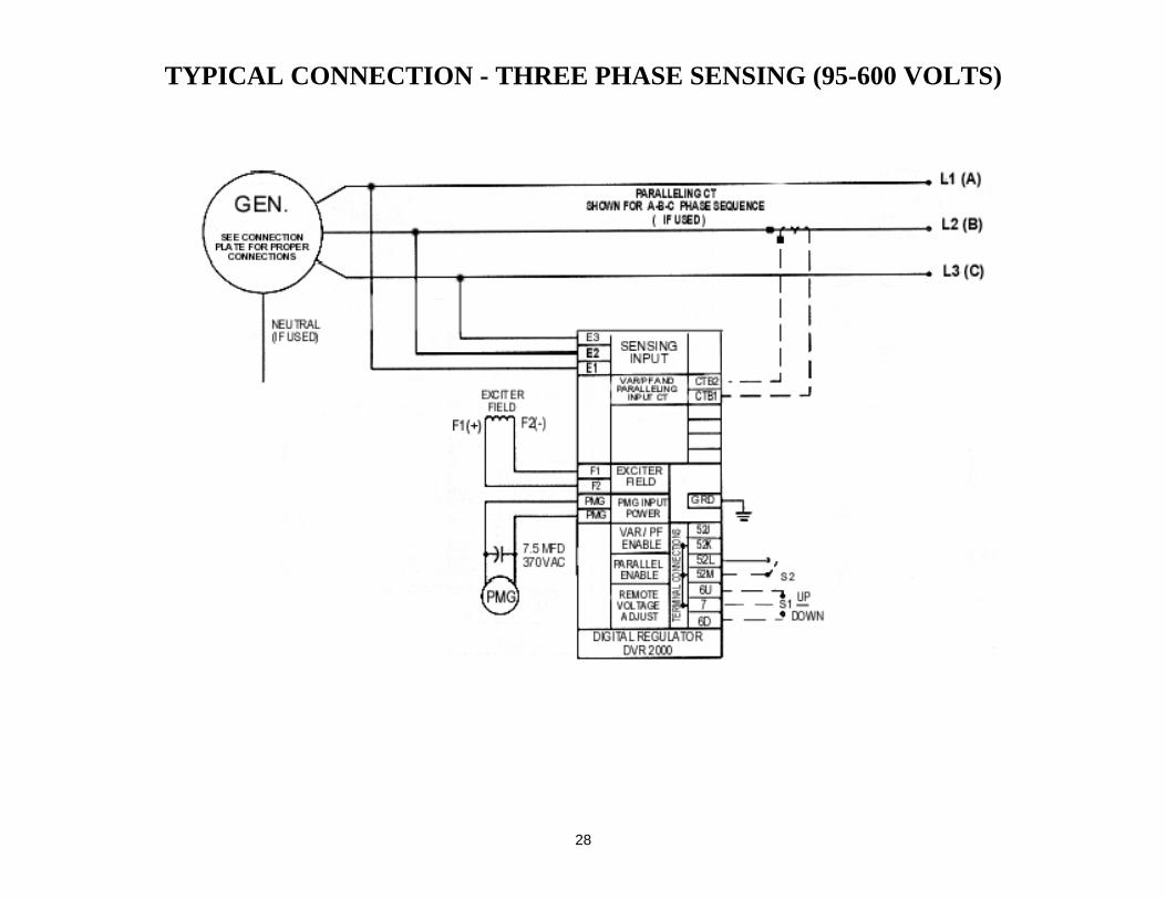
TYPICAL CONNECTION - THREE PHASE SENSING (95-600 VOLTS) ...................................................................28
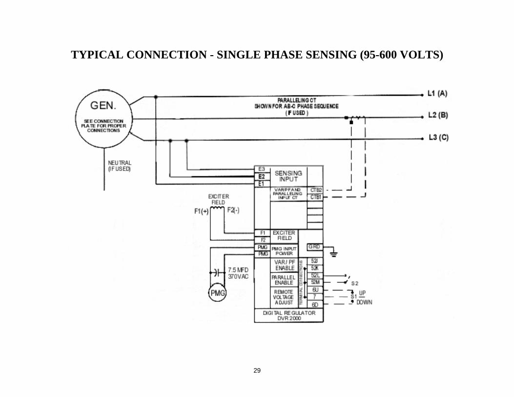
TYPICAL CONNECTION - SINGLE PHASE SENSING (95-600 VOLTS) ..................................................................29
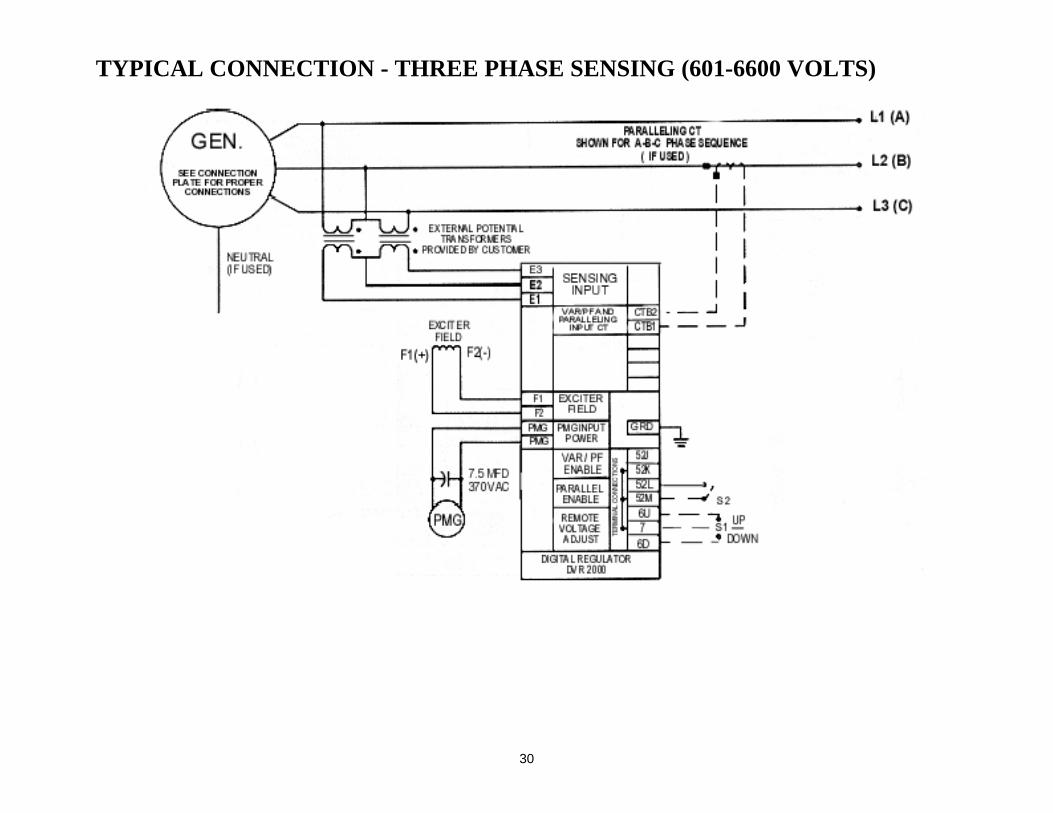
TYPICAL CONNECTION - THREE PHASE SENSING (601-6600 VOLTS) ...............................................................30
TYPICAL CONNECTION - SINGLE PHASE SENSING (601-6600 VOLTS) ..............................................................31
TYPICAL CONNECTION WITH REACTIVE DIFFERENTIAL PARALLELING ...................................................32THREE PHASE SENSING (95-600 VOLTS).................................................................................................................32
TYPICAL CONNECTION WITH VAR / PF CONTROL................................................................................................33THREE PHASE SENSING (95-600 VOLTS).................................................................................................................33
TYPICAL CONNECTION WITH VAR / PF CONTROL................................................................................................34SINGLE PHASE SENSING AND ISOLATION TRANSFORMER............................................................................34
4
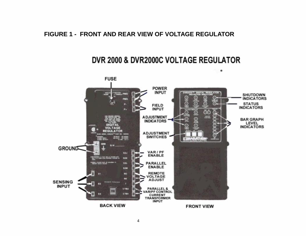
FIGURE 1 - FRONT AND REAR VIEW OF VOLTAGE REGULATOR
5
SECTION 1- INTRODUCTION
GENERAL DESCRIPTION
The DVR2000 Automatic Voltage Regulator is a sealed electronic solid statemicroprocessor based digital voltage regulator, which control the output of a brush less acgenerator by regulating the current into the exciter field. Unlike most regulators, the inputpower is from a multi-pole high frequency permanent magnet generator (PMG)incorporated within the main generator.
There is one basic model, the DVR2000 and one other model available, which is aDVR2000C.The "C” suffix indicates “VAR” or “PF” control is available.
SPECIFICATIONS
DVR2000 & DVR2000C
Sensing 95-600v, 25-420Hz
Sensing Mode RMS (1 or 3 Phase)
Input Requirements 180-240v, 250-300Hz
Continuous Output 75 Vdc at 3.0 Adc
Max Output 1-mm 150 Vdc at 7.5 Adc
Hot Field Resistance 18-25 Ohms
Regulation 0.25%
Response Less than 7 msec
Operating Temp. -40°C to +70°C
Storage Temperature -40°C to +85°C
Size10.4 L x 5.0 W x 2.8 D (26.4 x 12.7 x 7.l cm)
Weight 5.5 Lbs. (2.5 Kg)
Fuse Size and Type25x 1.25 5-ampLittelfuse 314005 orBussman ABC-5
Accessory Input Not Available
6
FEATURES -See Figure 1 for location of features on face of regulator
Sensing Voltage
The DVR2000 Digital Regulator is equipped for either 3-phase or 1-phase sensing. Thesensing voltage is adjustable over the entire range of 95-600v without the need forresetting transformer taps.
Single phase sensing is achieved by connecting terminal E2 and E3 to the same generatorterminal.
Parallel Operation
Provisions are included in the regulator to allow the paralleling of two or more generatorsusing either reactive droop or reactive differential (cross current) compensation with theaddition of an external 5 amp 5va current transformer.
Under Frequency Operation
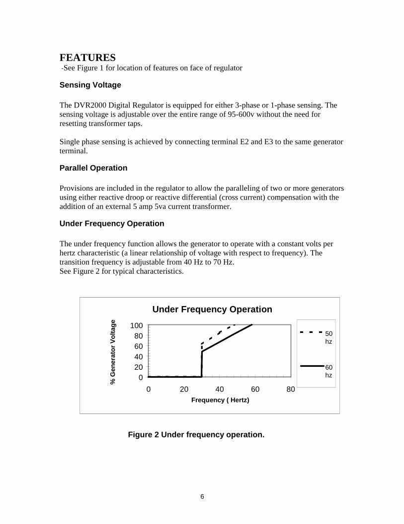
The under frequency function allows the generator to operate with a constant volts perhertz characteristic (a linear relationship of voltage with respect to frequency). Thetransition frequency is adjustable from 40 Hz to 70 Hz.See Figure 2 for typical characteristics.
Figure 2 Under frequency operation.
Under Frequency Operation
020406080
100
0 20 40 60 80Frequency ( Hertz)
% G
ener
ato
r V
olt
age
50hz
60hz
7
FEATURES
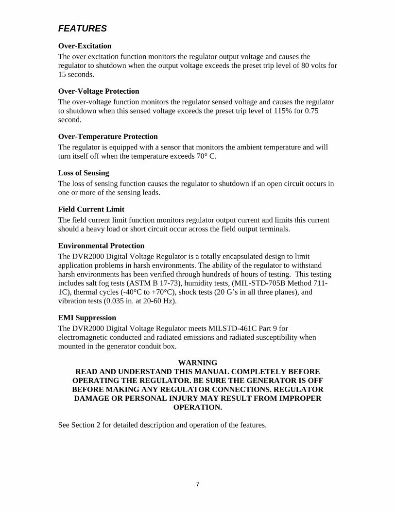
Over-ExcitationThe over excitation function monitors the regulator output voltage and causes theregulator to shutdown when the output voltage exceeds the preset trip level of 80 volts for15 seconds.
Over-Voltage ProtectionThe over-voltage function monitors the regulator sensed voltage and causes the regulatorto shutdown when this sensed voltage exceeds the preset trip level of 115% for 0.75second.
Over-Temperature ProtectionThe regulator is equipped with a sensor that monitors the ambient temperature and willturn itself off when the temperature exceeds 70° C.
Loss of SensingThe loss of sensing function causes the regulator to shutdown if an open circuit occurs inone or more of the sensing leads.
Field Current LimitThe field current limit function monitors regulator output current and limits this currentshould a heavy load or short circuit occur across the field output terminals.
Environmental ProtectionThe DVR2000 Digital Voltage Regulator is a totally encapsulated design to limitapplication problems in harsh environments. The ability of the regulator to withstandharsh environments has been verified through hundreds of hours of testing. This testingincludes salt fog tests (ASTM B 17-73), humidity tests, (MIL-STD-705B Method 711-1C), thermal cycles (-40°C to +70°C), shock tests (20 G’s in all three planes), andvibration tests (0.035 in. at 20-60 Hz).
EMI SuppressionThe DVR2000 Digital Voltage Regulator meets MILSTD-461C Part 9 forelectromagnetic conducted and radiated emissions and radiated susceptibility whenmounted in the generator conduit box.
WARNINGREAD AND UNDERSTAND THIS MANUAL COMPLETELY BEFORE
OPERATING THE REGULATOR. BE SURE THE GENERATOR IS OFFBEFORE MAKING ANY REGULATOR CONNECTIONS. REGULATORDAMAGE OR PERSONAL INJURY MAY RESULT FROM IMPROPER
OPERATION.
See Section 2 for detailed description and operation of the features.
8
SECTION 2 - OPERATION INSTRUCTIONS
MAIN REGULATOR
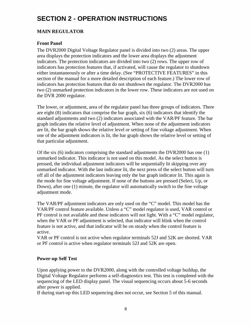
Front PanelThe DVR2000 Digital Voltage Regulator panel is divided into two (2) areas. The upperarea displays the protection indicators and the lower area displays the adjustmentindicators. The protection indicators are divided into two (2) rows. The upper row ofindicators has protection features that, if activated, will cause the regulator to shutdowneither instantaneously or after a time delay. (See “PROTECTIVE FEATURES” in thissection of the manual for a more detailed description of each feature.) The lower row ofindicators has protection features that do not shutdown the regulator. The DVR2000 hastwo (2) unmarked protection indicators in the lower row. These indicators are not used onthe DVR 2000 regulator.
The lower, or adjustment, area of the regulator panel has three groups of indicators. Thereare eight (8) indicators that comprise the bar graph, six (6) indicators that identify thestandard adjustments and two (2) indicators associated with the VAR/PF feature. The bargraph indicates the relative level of adjustment. When none of the adjustment indicatorsare lit, the bar graph shows the relative level or setting of fine voltage adjustment. Whenone of the adjustment indicators is lit, the bar graph shows the relative level or setting ofthat particular adjustment.
Of the six (6) indicators comprising the standard adjustments the DVR2000 has one (1)unmarked indicator. This indicator is not used on this model. As the select button ispressed, the individual adjustment indicators will be sequentially lit skipping over anyunmarked indicator. With the last indicator lit, the next press of the select button will turnoff all of the adjustment indicators leaving only the bar graph indicator lit. This again isthe mode for fine voltage adjustment. If none of the buttons are pressed (Select, Up, orDown), after one (1) minute, the regulator will automatically switch to the fine voltageadjustment mode.
The VAR/PF adjustment indicators are only used on the “C” model. This model has theVAR/PF control feature available. Unless a “C” model regulator is used, VAR control orPF control is not available and these indicators will not light. With a “C” model regulator,when the VAR or PF adjustment is selected, that indicator will blink when the controlfeature is not active, and that indicator will be on steady when the control feature isactive.VAR or PF control is not active when regulator terminals 52J and 52K are shorted. VARor PF control is active when regulator terminals 52J and 52K are open.
Power-up Self Test
Upon applying power to the DVR2000, along with the controlled voltage buildup, theDigital Voltage Regulator performs a self-diagnostics test. This test is completed with thesequencing of the LED display panel. The visual sequencing occurs about 5-6 secondsafter power is applied.If during start-up this LED sequencing does not occur, see Section 5 of this manual.
9
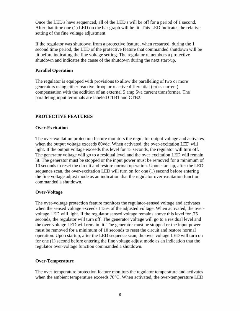
Once the LED's have sequenced, all of the LED's will be off for a period of 1 second.After that time one (1) LED on the bar graph will be lit. This LED indicates the relativesetting of the fine voltage adjustment.
If the regulator was shutdown from a protective feature, when restarted, during the 1second time period, the LED of the protective feature that commanded shutdown will belit before indicating the fine voltage setting. The regulator remembers a protectiveshutdown and indicates the cause of the shutdown during the next start-up.
Parallel Operation
The regulator is equipped with provisions to allow the paralleling of two or moregenerators using either reactive droop or reactive differential (cross current)compensation with the addition of an external 5 amp 5va current transformer. Theparalleling input terminals are labeled CTB1 and CTB2.
PROTECTIVE FEATURES
Over-Excitation
The over-excitation protection feature monitors the regulator output voltage and activateswhen the output voltage exceeds 80vdc. When activated, the over-excitation LED willlight. If the output voltage exceeds this level for 15 seconds, the regulator will turn off.The generator voltage will go to a residual level and the over-excitation LED will remainlit. The generator must be stopped or the input power must be removed for a minimum of10 seconds to reset the circuit and restore normal operation. Upon start-up, after the LEDsequence scan, the over-excitation LED will turn on for one (1) second before enteringthe fine voltage adjust mode as an indication that the regulator over-excitation functioncommanded a shutdown.
Over-Voltage
The over-voltage protection feature monitors the regulator-sensed voltage and activateswhen the sensed voltage exceeds 115% of the adjusted voltage. When activated, the over-voltage LED will light. If the regulator sensed voltage remains above this level for .75seconds, the regulator will turn off. The generator voltage will go to a residual level andthe over-voltage LED will remain lit. The generator must be stopped or the input powermust be removed for a minimum of 10 seconds to reset the circuit and restore normaloperation. Upon startup, after the LED sequence scan, the over-voltage LED will turn onfor one (1) second before entering the fine voltage adjust mode as an indication that theregulator over-voltage function commanded a shutdown.
Over-Temperature
The over-temperature protection feature monitors the regulator temperature and activateswhen the ambient temperature exceeds 70°C. When activated, the over-temperature LED
10
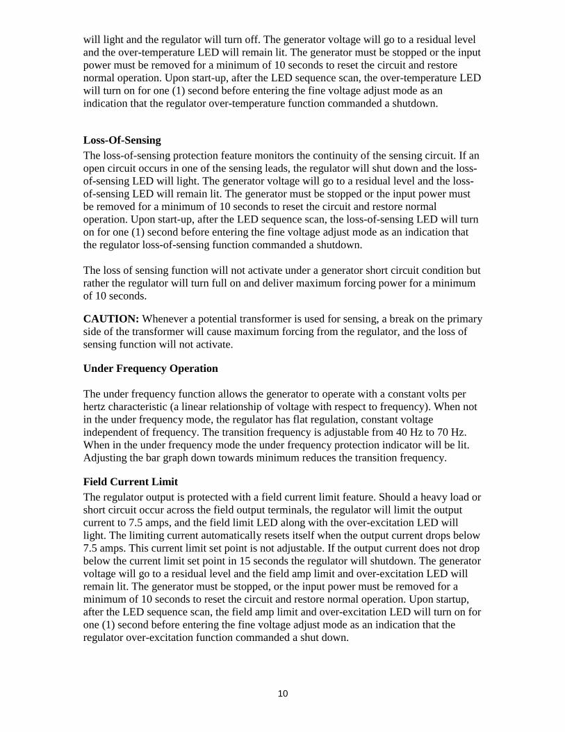
will light and the regulator will turn off. The generator voltage will go to a residual leveland the over-temperature LED will remain lit. The generator must be stopped or the inputpower must be removed for a minimum of 10 seconds to reset the circuit and restorenormal operation. Upon start-up, after the LED sequence scan, the over-temperature LEDwill turn on for one (1) second before entering the fine voltage adjust mode as anindication that the regulator over-temperature function commanded a shutdown.
Loss-Of-SensingThe loss-of-sensing protection feature monitors the continuity of the sensing circuit. If anopen circuit occurs in one of the sensing leads, the regulator will shut down and the loss-of-sensing LED will light. The generator voltage will go to a residual level and the loss-of-sensing LED will remain lit. The generator must be stopped or the input power mustbe removed for a minimum of 10 seconds to reset the circuit and restore normaloperation. Upon start-up, after the LED sequence scan, the loss-of-sensing LED will turnon for one (1) second before entering the fine voltage adjust mode as an indication thatthe regulator loss-of-sensing function commanded a shutdown.
The loss of sensing function will not activate under a generator short circuit condition butrather the regulator will turn full on and deliver maximum forcing power for a minimumof 10 seconds.
CAUTION: Whenever a potential transformer is used for sensing, a break on the primaryside of the transformer will cause maximum forcing from the regulator, and the loss ofsensing function will not activate.
Under Frequency Operation
The under frequency function allows the generator to operate with a constant volts perhertz characteristic (a linear relationship of voltage with respect to frequency). When notin the under frequency mode, the regulator has flat regulation, constant voltageindependent of frequency. The transition frequency is adjustable from 40 Hz to 70 Hz.When in the under frequency mode the under frequency protection indicator will be lit.Adjusting the bar graph down towards minimum reduces the transition frequency.
Field Current LimitThe regulator output is protected with a field current limit feature. Should a heavy load orshort circuit occur across the field output terminals, the regulator will limit the outputcurrent to 7.5 amps, and the field limit LED along with the over-excitation LED willlight. The limiting current automatically resets itself when the output current drops below7.5 amps. This current limit set point is not adjustable. If the output current does not dropbelow the current limit set point in 15 seconds the regulator will shutdown. The generatorvoltage will go to a residual level and the field amp limit and over-excitation LED willremain lit. The generator must be stopped, or the input power must be removed for aminimum of 10 seconds to reset the circuit and restore normal operation. Upon startup,after the LED sequence scan, the field amp limit and over-excitation LED will turn on forone (1) second before entering the fine voltage adjust mode as an indication that theregulator over-excitation function commanded a shut down.
11
SECTION 3 - INSTALLATION
MOUNTING
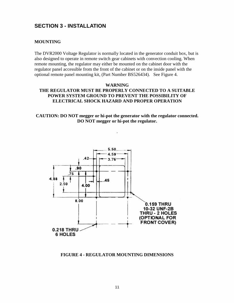
The DVR2000 Voltage Regulator is normally located in the generator conduit box, but isalso designed to operate in remote switch gear cabinets with convection cooling. Whenremote mounting, the regulator may either be mounted on the cabinet door with theregulator panel accessible from the front of the cabinet or on the inside panel with theoptional remote panel mounting kit, (Part Number BS526434). See Figure 4.
WARNINGTHE REGULATOR MUST BE PROPERLY CONNECTED TO A SUITABLE
POWER SYSTEM GROUND TO PREVENT THE POSSIBILITY OFELECTRICAL SHOCK HAZARD AND PROPER OPERATION
CAUTION: DO NOT megger or hi-pot the generator with the regulator connected.DO NOT megger or hi-pot the regulator.
.
FIGURE 4 - REGULATOR MOUNTING DIMENSIONS
12
INTERCONNECTIONS
WARNINGBE SURE GENERATOR IS STOPPED AND ALL POWER IS OFF
BEFORE MAKING ANY CONNECTIONS.
For typical wiring diagrams see “Outline Drawings and Diagrams” (Section 7).
CAUTION: For use on generator with output voltages greater than 600v,An external potential transformer must be used.
Whenever a potential transformer is used for sensing, an open circuit on theprimary side of the transformer will cause maximum forcing from the regulator, and theloss of sensing circuit will not activate. Assure that all connections on the primary side ofthe transformer are tight and secured from possible vibration.
REMOTE VOLTAGE ADJUST
If a remote voltage adjust is required, a single pole double throw spring return center offtoggle switch rated for 240v 1 amp is best suited as a remote adjust. To connect thisswitch for operation, the center pole or common terminal must be connected to regulatorterminal 7. The other two (2) poles or terminals are connected to regulator terminals 6Uand 6D. Care is required because “Input Power” voltages are present between 6U, 6D,and 7. This connection can be made using any wire gauges from 12 AWG-22 AWG. Theremote voltage adjust can be mounted up to l50 ft from the regulator.
SENSING VOLTAGE
The DVR2000 Digital Voltage Regulator comes equipped for 3-phase sensing asstandard. It can optionally be used with single phase sensing by connecting generatorterminal T1 to regulator sensing terminal El and generator terminal T3 to regulatorterminals E2 & E3.
POWER OUTPUT
The power output terminals of the regulator are labeled F+ and F-. These terminals areconnected to the generator field leads respectively. Power Input
The two power input terminals of the regulator are labeled PMG. The leads of thePermanent Magnet Generator are connected to these terminals.
PARALLELING INPUT
The DVR2000 Digital Voltage Regulator comes equipped with parallel provisions asstandard. The Paralleling input terminals are labeled CTB1 and CTB2. If paralleling isdesired, connect the leads from a standard 5 amp 5va current transformer to theseterminals.
13
The standard generator phase rotation is A-B-C to T1 -T2-T3 with CCW rotation whenfacing the conduit box or opposite drive end.With this phase rotation and 3-phase sensing, connect generator lead
T1 to regulator terminal El,T2 to regulator terminal E2, andT3 to regulator terminal E3
The paralleling transformer must be in the generator T2 lead with the H1 towards thegenerator and the XI to regulator terminal CTB2.
With single phase sensing, connect the generator sensing leads:
T1 to regulator terminal El,T3 to regulator terminal E2, and, E3
The paralleling transformer must be in the generator T2 lead with the H1 towards thegenerator and the Xl to regulator terminal CTB1.
CAUTION: The polarity and phasing of the current transformer and sensing connectionsmust be observed or improper operation will result.See Section 7 for typical connection diagrams.
To determine if the paralleling function is operating properly, see Section 4.
If a paralleling switch is desired, this switch or contacts are connected to regulatorterminals 52L and 52M. Paralleling is activated when regulator terminals 52L and 52Mare open. Paralleling is deactivated when regulator terminals 52L and 52M are shorted.
CAUTION: “Power Input” voltages are present between 52L and 52M.The paralleling switch DOES NOT short the CT terminals.Note: Regulator terminal 52M is internally common with terminal 7.
The current transformer used for paralleling may also be used for generator currentmetering.
FIELD FLASHING
A permanent magnet generator powers the "DVR2000 Digital Voltage Regulator" andfield flashing is not required or necessary.
14
SECTION 4 - ADJUSTMENTS AND START-UP PROCEDURE
CAUTION: Read and understand this section completely before attempting anyadjustments and starting the generator. If the adjustments do not produce thespecified results, proceed to the “Troubleshooting” section.
GENERALThe new DVR2000 Digital Voltage Regulator is designed such that all adjustments aremade outside of the conduit box.
In the adjustment section there are eight (8) LED's that indicate the adjustment feature,eight (8) LED's that comprise the bar graph level indicator, and three (3) push buttons.
The three, (3), push buttons are:1.) “Select” - Systematically selects the adjustment feature by successive presses ofthe button.2.) “Up” - Increases the level of the selected adjustment feature.3.) “Down” - Decreases the level of the selected adjustment feature.
Successive presses of the “Select” button will step through the various adjustmentfeatures. Once the desired adjustment feature is lit the “Up/Down” buttons will increaseor decrease the level of the adjustment feature indicated. Once the proper level is reached,the “select” button must be pressed once more in order to save the new level in memory.
While in the “Select” mode, if no button is pressed for a period of one (1) minute, theregulator will automatically save the new level in memory. However, if regulator poweris interrupted before the automatic save feature is commanded, that level of adjustmentwill be lost and the regulator will recall the last previously stored level.The “Select” button must be pressed in order to step through the adjustment features. The“Up! Down” buttons may be successively pressed to increase or decrease the level, or ifheld down, the level will automatically increase or decrease at a rate of 2-increments persecond. If at any time both the “Up” and the “Down” button are pressed simultaneouslythe “Up” button takes precedence.When stepping through the adjustment features, only those features available can beselected. Only regulators with a “C” in the model number will allow the VAR Control orPF Control to be selected. Those models without a “C” in the model number will notallow the VAR Control or PF Control to be selected, and they will be skipped over.
There are up to eight (8) adjustments available on the DVR2000 Digital VoltageRegulator. They are:
1.) Fine Voltage2.) Coarse Voltage3.) Stability Range4.) Stability5.) Under Frequency6.) Droop7.) Power Factor Control8.) VAR Control
15
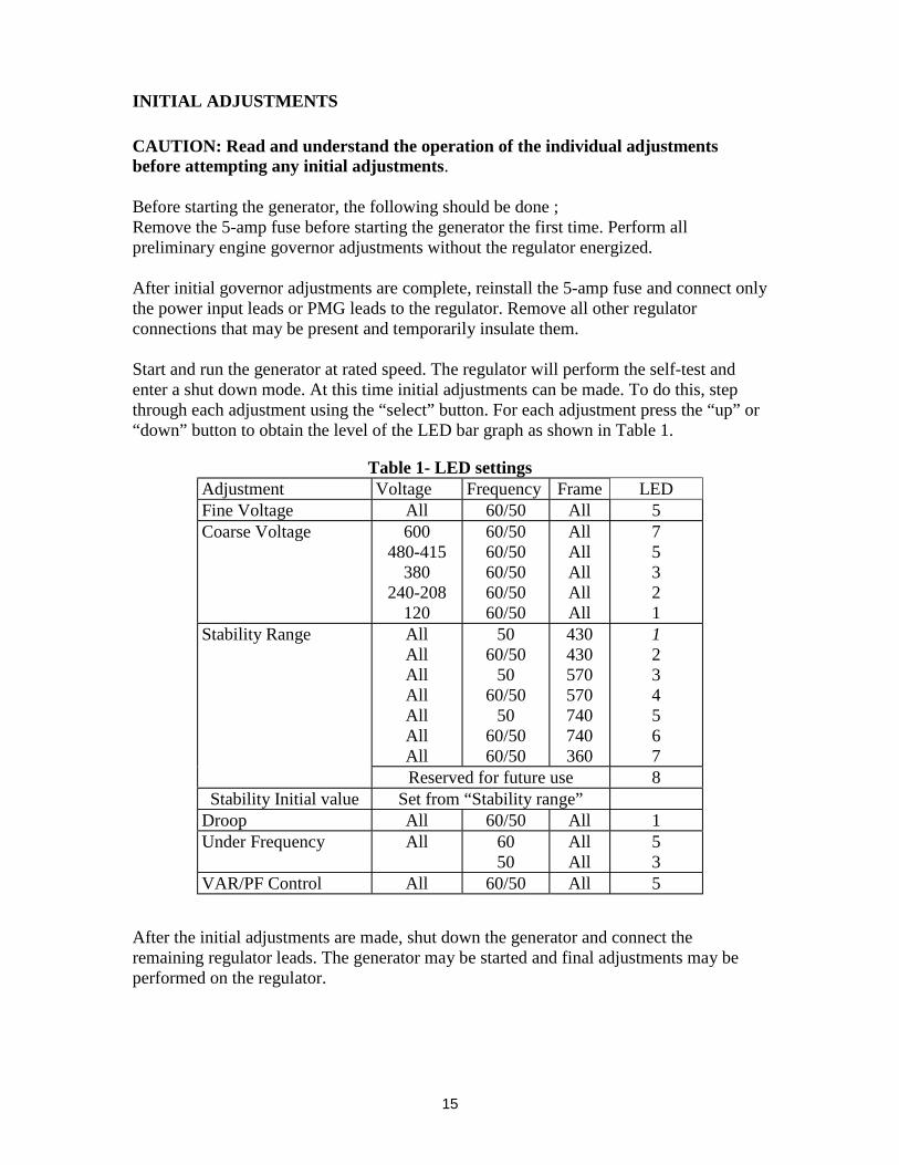
INITIAL ADJUSTMENTS
CAUTION: Read and understand the operation of the individual adjustmentsbefore attempting any initial adjustments.
Before starting the generator, the following should be done ;Remove the 5-amp fuse before starting the generator the first time. Perform allpreliminary engine governor adjustments without the regulator energized.
After initial governor adjustments are complete, reinstall the 5-amp fuse and connect onlythe power input leads or PMG leads to the regulator. Remove all other regulatorconnections that may be present and temporarily insulate them.
Start and run the generator at rated speed. The regulator will perform the self-test andenter a shut down mode. At this time initial adjustments can be made. To do this, stepthrough each adjustment using the “select” button. For each adjustment press the “up” or“down” button to obtain the level of the LED bar graph as shown in Table 1.
Table 1- LED settingsAdjustment Voltage Frequency Frame LEDFine Voltage All 60/50 All 5Coarse Voltage 600
480-415380
240-208120
60/5060/5060/5060/5060/50
AllAllAllAllAll
75321
Stability Range AllAllAllAllAllAllAll
5060/50
5060/50
5060/5060/50
430430570570740740360
1234567
Reserved for future use 8Stability Initial value Set from “Stability range”
Droop All 60/50 All 1Under Frequency All 60
50AllAll
53
VAR/PF Control All 60/50 All 5
After the initial adjustments are made, shut down the generator and connect theremaining regulator leads. The generator may be started and final adjustments may beperformed on the regulator.
16
FINE VOLTAGE ADJUSTMENT
When none of the adjustment features are selected, the “Up/Down” buttons act as the“Fine Voltage” adjustment and the bar graph is a relative indication of that adjustment.Every Up/Down adjustments of the fine voltage adjust feature will increase or decreasethe sensed voltage about 0.5 volts. The range of the “Fine Voltage” adjustment is +/- 60vor 120v (min. to max.) of the sensed voltage (See Table 2). After adjustment is made, the“Select” button must be pressed in order to save new level. If no button is pressed for aperiod of one (1) minute, the regulator will automatically save the setting. If regulatorpower is interrupted before one (1) minute has passed, the new setting will be lost.
COARSE VOLTAGE ADJUSTMENT
To select “Coarse Voltage” press the “Select” button until the “Coarse Voltage” LED islit. When selected, the “Up/Down” buttons act as the coarse voltage adjustment and thebar graph is a relative indication of that adjustment. Every Up/Down adjustments of the"Coarse Voltage" adjust will increase or decrease the sensed voltage about 6 volts. Therange of the coarse voltage adjustment is 95 - 600v (See Table 2). After adjustment ismade, the “Select” button must be pressed in order to save new level. If no button ispressed for a period of one (1) minute, the regulator will automatically save the setting. Ifregulator power is interrupted before one (1) minute has passed, the new setting will belost.
REMOTE VOLTAGE ADJUSTMENT
There is a third voltage adjustment, which is not located on the front panel. It is theremote voltage adjustment. The remote voltages adjust functions by remotely changingthe fine voltage adjustment setting at the rate of 1 volt / sec. of switch contact. Unlike theregulator pushbuttons, the remote voltages adjust only functions when none of theadjustment features are selected. When any of the adjustment features are selected theremote voltage adjust is disabled. After adjustment is made, the “Select” button must bepressed in order to save the new level. If no button is pressed for a period of one (1)minute, the regulator will automatically save the setting. If regulator power is interruptedbefore one (1) minute has passed, the new setting will be lost.
The remote voltage adjust is connected to terminals 6U, 6D and 7, respectively. A singlepole double throw spring return, with center off, toggle switch rated for 240v lamp is bestsuited as a remote adjusts. To connect this switch for operation, the center pole orcommon terminal must be connected to regulator terminal 7. The other two (2) poles orterminals are connected to regulator terminals 6U and 6D. Care is required because“Input Power” voltages are present between 6U & 7 and 6D & 7.
17
STABILITY RANGE ADJUSTMENT
The “Stability Range” selects the proper control parameters for the frame size generatorand excitation system used. There are eight possible ranges. With the “Stability Range”LED lit every push of the “Up” or “Down” button will increase or decrease the bar graphone (1) LED.
To select “Stability Range” press the “Select” button until the “Stability Range” LED islit. The LED bar graph will indicate the present stability range level. If this is the properrange for the frame size as shown in Table I, then proceed on to the next adjustment. Ifanother stability range level is desired then press the “Up” or “Down” button until theproper LED of the bar graph is lit. Press the “Select” once more to exit “Stability Range”and save the new value. If no button is pressed for a period of one (1) minute theregulator will automatically save the setting. If regulator power is interrupted before one(1) minute has passed the new setting will be lost.After selecting “Stability Range” as indicated, the regulator will automatically select astability level that is acceptable for most applications (See “Stability Adjustment”)
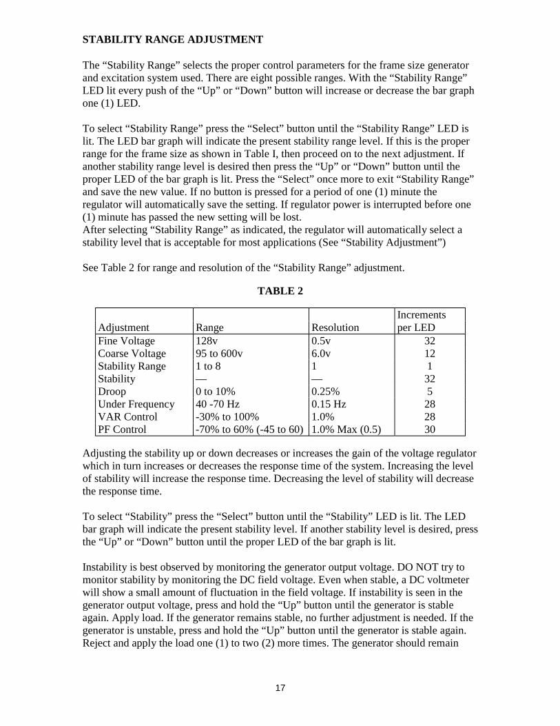
See Table 2 for range and resolution of the “Stability Range” adjustment.
TABLE 2
IncrementsAdjustment Range Resolution per LEDFine Voltage 128v 0.5v 32Coarse Voltage 95 to 600v 6.0v 12Stability Range 1 to 8 1 1Stability — — 32Droop 0 to 10% 0.25% 5Under Frequency 40 -70 Hz 0.15 Hz 28VAR Control -30% to 100% 1.0% 28PF Control -70% to 60% (-45 to 60) 1.0% Max (0.5) 30
Adjusting the stability up or down decreases or increases the gain of the voltage regulatorwhich in turn increases or decreases the response time of the system. Increasing the levelof stability will increase the response time. Decreasing the level of stability will decreasethe response time.
To select “Stability” press the “Select” button until the “Stability” LED is lit. The LEDbar graph will indicate the present stability level. If another stability level is desired, pressthe “Up” or “Down” button until the proper LED of the bar graph is lit.
Instability is best observed by monitoring the generator output voltage. DO NOT try tomonitor stability by monitoring the DC field voltage. Even when stable, a DC voltmeterwill show a small amount of fluctuation in the field voltage. If instability is seen in thegenerator output voltage, press and hold the “Up” button until the generator is stableagain. Apply load. If the generator remains stable, no further adjustment is needed. If thegenerator is unstable, press and hold the “Up” button until the generator is stable again.Reject and apply the load one (1) to two (2) more times. The generator should remain
18
stable. If the generator is not stable or if the response is too slow, then either increase ordecrease the stability level as desired one (1) to two (‘2) increments at a time applyingand rejecting load between each adjustment until optimum performance is achieved.Press the “Select” once more to exit “Stability” and save the new value. If no button ispressed for a period of one (1) minute, the regulator will automatically save the setting. Ifregulator power is interrupted before one (1) minute has passed, the new setting will belost.
UNDER FREQUENCY ADJUSTMENT
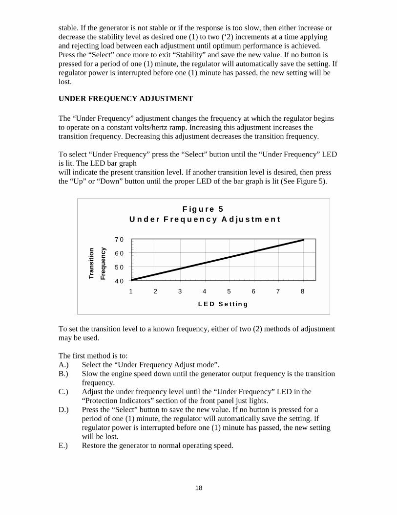
The “Under Frequency” adjustment changes the frequency at which the regulator beginsto operate on a constant volts/hertz ramp. Increasing this adjustment increases thetransition frequency. Decreasing this adjustment decreases the transition frequency.
To select “Under Frequency” press the “Select” button until the “Under Frequency” LEDis lit. The LED bar graphwill indicate the present transition level. If another transition level is desired, then pressthe “Up” or “Down” button until the proper LED of the bar graph is lit (See Figure 5).
To set the transition level to a known frequency, either of two (2) methods of adjustmentmay be used.
The first method is to:A.) Select the “Under Frequency Adjust mode”.B.) Slow the engine speed down until the generator output frequency is the transition
frequency.C.) Adjust the under frequency level until the “Under Frequency” LED in the
“Protection Indicators” section of the front panel just lights.D.) Press the “Select” button to save the new value. If no button is pressed for a
period of one (1) minute, the regulator will automatically save the setting. Ifregulator power is interrupted before one (1) minute has passed, the new settingwill be lost.
E.) Restore the generator to normal operating speed.
F ig u r e 5 U n d e r F r e q u e n c y A d ju s tm e n t
4 0
5 0
6 0
7 0
1 2 3 4 5 6 7 8
L E D S e t t in g
Tra
ns
itio
n
Fre
qu
ency
19
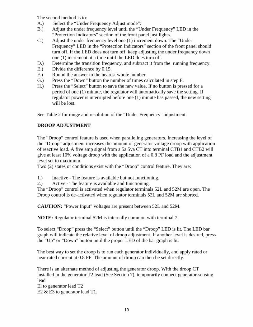
The second method is to:A.) Select the “Under Frequency Adjust mode”:B.) Adjust the under frequency level until the “Under Frequency” LED in the
“Protection Indicators” section of the front panel just lights.C.) Adjust the under frequency level one (1) increment down. The “Under
Frequency” LED in the “Protection Indicators” section of the front panel shouldturn off. If the LED does not turn off, keep adjusting the under frequency downone (1) increment at a time until the LED does turn off.
D.) Determine the transition frequency, and subtract it from the running frequency.E.) Divide the difference by 0.15.F.) Round the answer to the nearest whole number.G.) Press the “Down” button the number of times calculated in step F.H.) Press the “Select” button to save the new value. If no button is pressed for a
period of one (1) minute, the regulator will automatically save the setting. Ifregulator power is interrupted before one (1) minute has passed, the new settingwill be lost.
See Table 2 for range and resolution of the “Under Frequency” adjustment.
DROOP ADJUSTMENT
The “Droop” control feature is used when paralleling generators. Increasing the level ofthe “Droop” adjustment increases the amount of generator voltage droop with applicationof reactive load. A five amp signal from a 5a 5va CT into terminal CTB1 and CTB2 willgive at least 10% voltage droop with the application of a 0.8 PF load and the adjustmentlevel set to maximum.Two (2) states or conditions exist with the “Droop” control feature. They are:
1.) Inactive - The feature is available but not functioning.2.) Active - The feature is available and functioning.The “Droop” control is activated when regulator terminals 52L and 52M are open. TheDroop control is de-activated when regulator terminals 52L and 52M are shorted.
CAUTION: “Power Input” voltages are present between 52L and 52M.
NOTE: Regulator terminal 52M is internally common with terminal 7.
To select “Droop” press the “Select” button until the “Droop” LED is lit. The LED bargraph will indicate the relative level of droop adjustment. If another level is desired, pressthe “Up” or “Down” button until the proper LED of the bar graph is lit.
The best way to set the droop is to run each generator individually, and apply rated ornear rated current at 0.8 PF. The amount of droop can then be set directly.
There is an alternate method of adjusting the generator droop. With the droop CTinstalled in the generator T2 lead (See Section 7), temporarily connect generator-sensingleadEl to generator lead T2E2 & E3 to generator lead T1.
20
WARNING: BE SURE GENERATOR IS STOPPEDAND ALL POWER IS OFF BEFORE MAKING ANY CONNECTIONS.
Run each generator individually and apply rated or near rated current at unity PF. Theamount of droop can then be set by adjusting the "Droop" adjustment as needed for theapplication
If when adjusting generator droop the generator output voltage does not decrease withapplication of load, recheck the CT polarity and the sensing lead connections.
After the adjustments are complete, reconnect the regulator sensing leads as outlined inSection 7. When the generators are operated in parallel they will share load equally. If noreactive load is present, the generator voltage should not droop. If it does droop, rechecksensing connections, CT connections, and CT polarity. If necessary repeat the adjustmentprocedure.
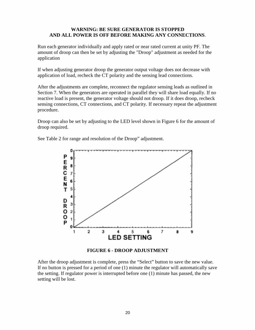
Droop can also be set by adjusting to the LED level shown in Figure 6 for the amount ofdroop required.
See Table 2 for range and resolution of the Droop” adjustment.
FIGURE 6 - DROOP ADJUSTMENT
After the droop adjustment is complete, press the “Select” button to save the new value.If no button is pressed for a period of one (1) minute the regulator will automatically savethe setting. If regulator power is interrupted before one (1) minute has passed, the newsetting will be lost.
21
REACTIVE DIFFERENTIAL (CROSS CURRENT) ADJUSTMENTWith the cross current loop disabled, set up the generators for satisfactory simple droopoperation. Then reconnect the cross current loop retaining all settings. Operate the systemto verify satisfactory performance.
When operating in parallel reactive differential mode (cross current), attention must bepaid to the use of the burden resistor shown on the connection diagram. The burden resis-tor should have a value approximately ten (10) times the cross current loop resistance forproper differential operation. The value of 0.1 ohm is a suggested minimum value. Thevolt-ampere (VA) capacity of the paralleling Current Transformers should be consideredafter sizing the burden resistor.
VAR/PF ADJUSTMENT
The “VAR/PF” control feature is used when paralleling a generator to utility. “VAR” or“PF” control is only available on “C” model regulators. Increasing the level of the“VAR” or “PF” adjustment increases the amount of field excitation. Decreasing the levelof the “VAR” or “PF” adjustment decreases the amount of field excitation.
Two (2) states or conditions exist with the “VAR” or “PF” control feature. They are:1.) Inactive - The feature is available but not functioning.2.) Active - The feature is available and functioning.
The VAR or PF control is activated when regulator terminals 52J and 52K are open.The VAR or PF control is de-activated when regulator terminals 52J and 52K are shorted.CAUTION: “Power Input” voltage are present between 52J and 52K.NOTE: Regulator terminal 52K is internally common with terminal 7.
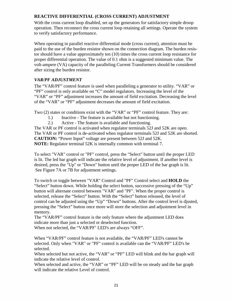
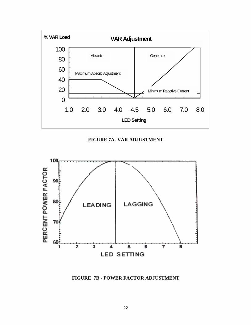
To select "VAR" control or "PF" control, press the "Select" button until the proper LEDis lit. The led bar graph will indicate the relative level of adjustment. If another level isdesired, press the "Up" or "Down" button until the proper LED of the bar graph is lit. See Figure 7A or 7B for adjustment settings.
To switch or toggle between "VAR" Control and "PF" Control select and HOLD the“Select” button down. While holding the select button, successive pressing of the “Up”button will alternate control between "VAR" and "PF". When the proper control isselected, release the “Select” button. With the “Select” button released, the level ofcontrol can be adjusted using the “Up” “Down” buttons. After the control level is djusted,pressing the “Select” button once more will store the selection and adjustment level inmemory.The “VAR/PF” control feature is the only feature where the adjustment LED doesindicate more than just a selected or deselected function.When not selected, the “VAR/PF’ LED's are always “OFF”.
When “VAR/PF” control feature is not available, the “VAR/PF” LED's cannot beselected. Only when "VAR" or "PF" control is available can the “VAR/PF” LED's beselected.When selected but not active, the “VAR” or “PF” LED will blink and the bar graph willindicate the relative level of control.When selected and active, the “VAR” or “PF” LED will be on steady and the bar graphwill indicate the relative Level of control.
22
FIGURE 7A- VAR ADJUSTMENT
FIGURE 7B - POWER FACTOR ADJUSTMENT
VAR Adjustment
0
20
40
60
80
100
1.0 2.0 3.0 4.0 4.5 5.0 6.0 7.0 8.0
LED Setting
% VAR Load
Absorb Generate
Maximum Absorb Adjustment
Minimum Reactive Current
23
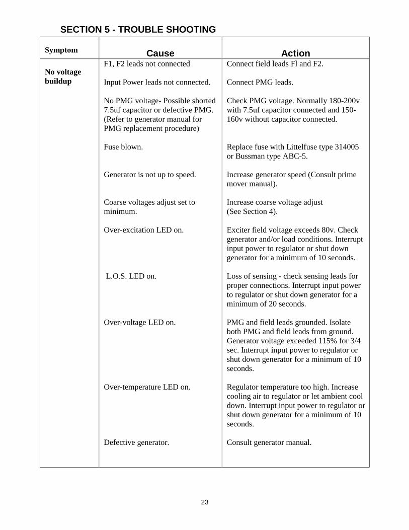
SECTION 5 - TROUBLE SHOOTING
Symptom Cause Action
No voltagebuildup
F1, F2 leads not connected
Input Power leads not connected.
No PMG voltage- Possible shorted7.5uf capacitor or defective PMG.(Refer to generator manual forPMG replacement procedure)
Fuse blown.
Generator is not up to speed.
Coarse voltages adjust set tominimum.
Over-excitation LED on.
L.O.S. LED on.
Over-voltage LED on.
Over-temperature LED on.
Defective generator.
Connect field leads Fl and F2.
Connect PMG leads.
Check PMG voltage. Normally 180-200vwith 7.5uf capacitor connected and 150-160v without capacitor connected.
Replace fuse with Littelfuse type 314005or Bussman type ABC-5.
Increase generator speed (Consult primemover manual).
Increase coarse voltage adjust(See Section 4).
Exciter field voltage exceeds 80v. Checkgenerator and/or load conditions. Interruptinput power to regulator or shut downgenerator for a minimum of 10 seconds.
Loss of sensing - check sensing leads forproper connections. Interrupt input powerto regulator or shut down generator for aminimum of 20 seconds.
PMG and field leads grounded. Isolateboth PMG and field leads from ground.Generator voltage exceeded 115% for 3/4sec. Interrupt input power to regulator orshut down generator for a minimum of 10seconds.
Regulator temperature too high. Increasecooling air to regulator or let ambient cooldown. Interrupt input power to regulator orshut down generator for a minimum of 10seconds.
Consult generator manual.
24
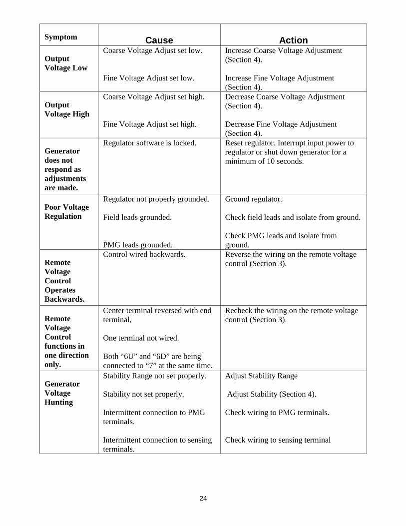
Symptom Cause Action
OutputVoltage Low
Coarse Voltage Adjust set low.
Fine Voltage Adjust set low.
Increase Coarse Voltage Adjustment(Section 4).
Increase Fine Voltage Adjustment(Section 4).
OutputVoltage High
Coarse Voltage Adjust set high.
Fine Voltage Adjust set high.
Decrease Coarse Voltage Adjustment(Section 4).
Decrease Fine Voltage Adjustment(Section 4).
Generatordoes notrespond asadjustmentsare made.
Regulator software is locked. Reset regulator. Interrupt input power toregulator or shut down generator for aminimum of 10 seconds.
Poor VoltageRegulation
Regulator not properly grounded.
Field leads grounded.
PMG leads grounded.
Ground regulator.
Check field leads and isolate from ground.
Check PMG leads and isolate fromground.
RemoteVoltageControlOperatesBackwards.
Control wired backwards. Reverse the wiring on the remote voltagecontrol (Section 3).
RemoteVoltageControlfunctions inone directiononly.
Center terminal reversed with endterminal,
One terminal not wired.
Both “6U” and “6D” are beingconnected to “7” at the same time.
Recheck the wiring on the remote voltagecontrol (Section 3).
GeneratorVoltageHunting
Stability Range not set properly.
Stability not set properly.
Intermittent connection to PMGterminals.
Intermittent connection to sensingterminals.
Adjust Stability Range
Adjust Stability (Section 4).
Check wiring to PMG terminals.
Check wiring to sensing terminal
25
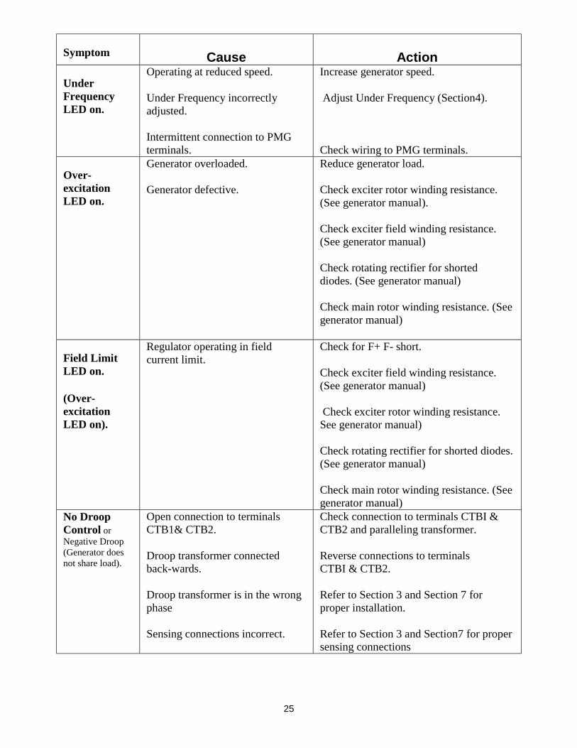
Symptom Cause Action
UnderFrequencyLED on.
Operating at reduced speed.
Under Frequency incorrectlyadjusted.
Intermittent connection to PMGterminals.
Increase generator speed.
Adjust Under Frequency (Section4).
Check wiring to PMG terminals.
Over-excitationLED on.
Generator overloaded.
Generator defective.
Reduce generator load.
Check exciter rotor winding resistance.(See generator manual).
Check exciter field winding resistance.(See generator manual)
Check rotating rectifier for shorteddiodes. (See generator manual)
Check main rotor winding resistance. (Seegenerator manual)
Field LimitLED on.
(Over-excitationLED on).
Regulator operating in fieldcurrent limit.
Check for F+ F- short.
Check exciter field winding resistance.(See generator manual)
Check exciter rotor winding resistance.See generator manual)
Check rotating rectifier for shorted diodes.(See generator manual)
Check main rotor winding resistance. (Seegenerator manual)
No DroopControl orNegative Droop(Generator doesnot share load).
Open connection to terminalsCTB1& CTB2.
Droop transformer connectedback-wards.
Droop transformer is in the wrongphase
Sensing connections incorrect.
Check connection to terminals CTBI &CTB2 and paralleling transformer.
Reverse connections to terminalsCTBI & CTB2.
Refer to Section 3 and Section 7 forproper installation.
Refer to Section 3 and Section7 for propersensing connections
26
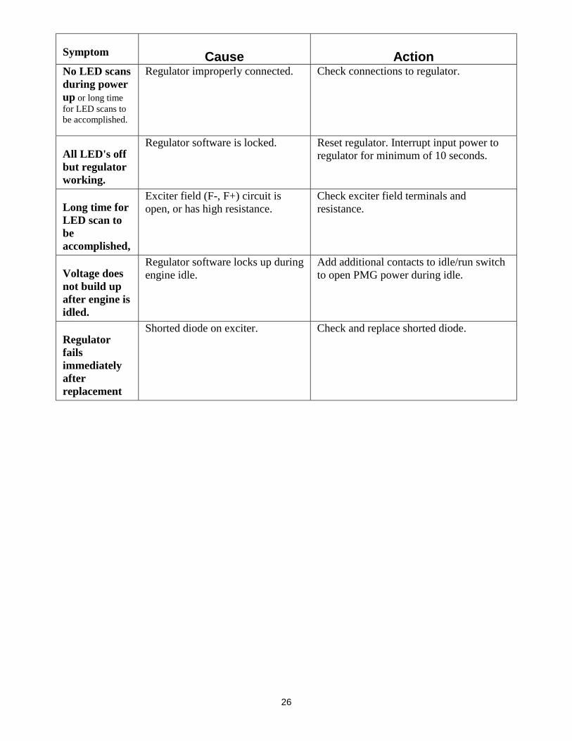
Symptom Cause ActionNo LED scansduring powerup or long timefor LED scans tobe accomplished.
Regulator improperly connected. Check connections to regulator.
All LED's offbut regulatorworking.
Regulator software is locked. Reset regulator. Interrupt input power toregulator for minimum of 10 seconds.
Long time forLED scan tobeaccomplished,
Exciter field (F-, F+) circuit isopen, or has high resistance.
Check exciter field terminals andresistance.
Voltage doesnot build upafter engine isidled.
Regulator software locks up duringengine idle.
Add additional contacts to idle/run switchto open PMG power during idle.
Regulatorfailsimmediatelyafterreplacement
Shorted diode on exciter. Check and replace shorted diode.
27
SECTION 7 - DRAWINGS
DIMENSIONS OF THE DVR2000 & DVR2000C
28
TYPICAL CONNECTION - THREE PHASE SENSING (95-600 VOLTS)
29
TYPICAL CONNECTION - SINGLE PHASE SENSING (95-600 VOLTS)
30
TYPICAL CONNECTION - THREE PHASE SENSING (601-6600 VOLTS)
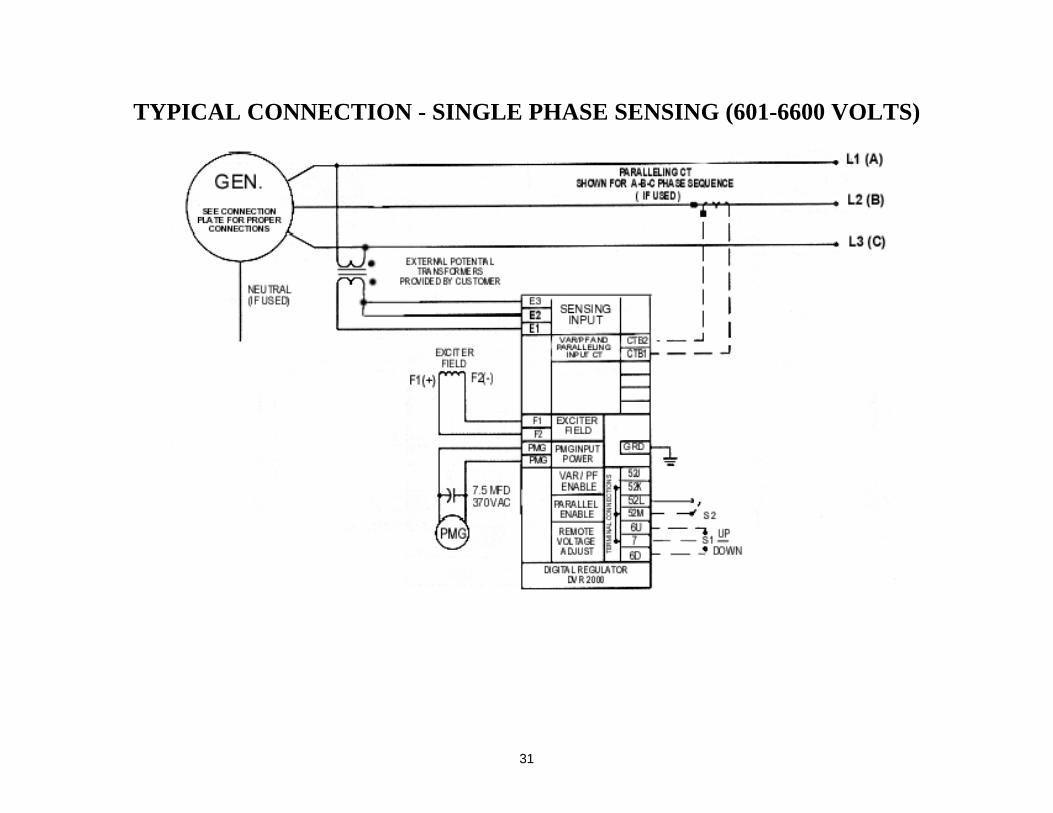
31
TYPICAL CONNECTION - SINGLE PHASE SENSING (601-6600 VOLTS)
32
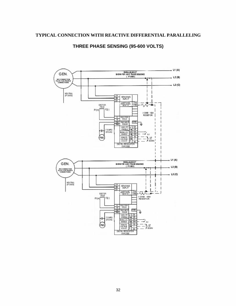
TYPICAL CONNECTION WITH REACTIVE DIFFERENTIAL PARALLELING
THREE PHASE SENSING (95-600 VOLTS)
33
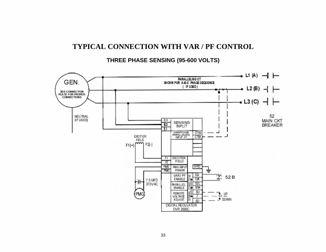
TYPICAL CONNECTION WITH VAR / PF CONTROL
THREE PHASE SENSING (95-600 VOLTS)
34
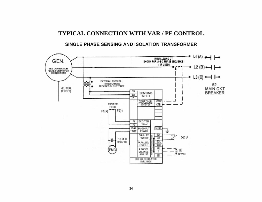
TYPICAL CONNECTION WITH VAR / PF CONTROL
SINGLE PHASE SENSING AND ISOLATION TRANSFORMER