Embed Size (px)
Citation preview
Acta Biomaterialia 8 (2012) 916–923
Contents lists available at SciVerse ScienceDirect
Acta Biomaterialia
journal homepage: www.elsevier .com/locate /ac tabiomat
Magnesium alloys as body implants: Fracture mechanism under dynamicand static loadings in a physiological environment
Lokesh Choudhary a, R.K. Singh Raman a,b,⇑a Department of Mechanical & Aerospace Engineering, Monash University, Melbourne, VIC-3800, Australiab Department of Chemical Engineering, Monash University, Melbourne, VIC-3800, Australia
a r t i c l e i n f o
Article history:Received 15 July 2011Received in revised form 23 October 2011Accepted 24 October 2011Available online 31 October 2011
Keywords:Magnesium alloy AZ91DTemporary implantsStress corrosion cracking (SCC)Slow strain rate tensile (SSRT)Circumferential notch tensile (CNT)
1742-7061/$ - see front matter � 2011 Acta Materialdoi:10.1016/j.actbio.2011.10.031
⇑ Corresponding author at: Department of MechaniMonash University, Melbourne, VIC-3800, Australia. T3 99051825.
E-mail address: [email protected] (R.K. Si
a b s t r a c t
It is essential that a metallic implant material possesses adequate resistance to cracking/fracture underthe synergistic action of a corrosive physiological environment and mechanical loading (i.e. stress corro-sion cracking (SCC)), before the implant can be put to actual use. This paper presents a critique of the fun-damental issues with an assessment of SCC of a rapidly corroding material such as magnesium alloys, anddescribes an investigation into the mechanism of SCC of a magnesium alloy in a physiological environ-ment. The SCC susceptibility of the alloy in a simulated human body fluid was established by slow strainrate tensile (SSRT) testing using smooth specimens under different electrochemical conditions for under-standing the mechanism of SCC. However, to assess the life of the implant devices that often possess finemicro-cracks, SCC susceptibility of notched specimens was investigated by circumferential notch tensile(CNT) testing. CNT tests also produced important design data, i.e. threshold stress intensity for SCC (KISCC)and SCC crack growth rate. Fractographic features of SCC were examined using scanning electron micros-copy. The SSRT and CNT results, together with fractographic evidence, confirmed the SCC susceptibility ofboth smooth and notched specimens of a magnesium alloy in the physiological environment.
� 2011 Acta Materialia Inc. Published by Elsevier Ltd. All rights reserved.
1. Introduction
The traditional implant materials, namely titanium alloys,stainless steels and cobalt–chromium alloys, possess excellentload-bearing capabilities and resistance to fatigue, wear and corro-sion. However, when these traditional alloys are used as temporaryimplant devices, such as plates, screws, and wires, a second surgeryis required to remove the implant after the tissues have healed,which markedly increases the health care cost. Also, there is anincreased risk of local inflammation due to the potential releaseof cytotoxic ions as well as the physical irritation due to the rigidityof these traditional implant devices. Moreover, the mechanicalproperties of traditional implants differ vastly from those of humanbones, and thus can cause stress shielding.
Recently, magnesium and its alloys have attracted increasinginterest as innovative biodegradable materials, particularly fortheir potential use as temporary orthopedic implants [1–7]. Thefundamental properties of magnesium make it quite suitable forthis application, namely low density (q) = 1.74–2.0 g cm�3, andelastic modulus (E) = 41–45 GPa, both of which are similar to the
ia Inc. Published by Elsevier Ltd. A
cal & Aerospace Engineering,el.: +61 3 99053671; fax: +61
ngh Raman).
corresponding properties of human bones (q = 1.8–2.1 g cm�3;E = 3–20 GPa) [3,8]. Magnesium is not only biocompatible but alsoessential to human metabolism as a cofactor for many enzymes[3,4], and thus, unlike traditional implant materials, the degrada-tion products of magnesium are not toxic to the human physiology.In fact, magnesium ions that are produced as a result of the degra-dation are reported to aid the growth and healing of tissues [8].Further, any excess magnesium is harmlessly excreted with theurine [4].
In spite of the advantageous properties of magnesium, its alloyshave rarely been used as human body implants. The major draw-back in the use of magnesium alloys as implants is that they tendto corrode very quickly in the chloride solutions [9], includingphysiological environment (which has a pH = 7.4–7.6) [8,10–15],thereby losing their mechanical integrity before the expected ser-vice life. Though these limitations have ruled out any effectiveuse of magnesium alloys as permanent implants, it is interestingthat the magnesium alloys could still be used as biodegradabletemporary implant devices such as plates, wires, stents, pins, andscrews. In fact, in such use, the susceptibility of magnesium to rapidelectrochemical dissolution (corrosion) can be exploited. Becausemagnesium can dissolve/corrode away in the chloride-containingaqueous solutions (such as the physiological environment)[5–8,11,13,14], it may be possible to obviate the need for secondsurgery. However, before such application, it will be essential to
ll rights reserved.
Table 1Chemical composition of AZ91D.
Element Mg Al Zn Mn Fe Ce Si Cu
wt.% Bal 8.81 0.79 0.21 0.003 <0.01 <0.01 0.003
Table 2Amount of reagents for preparing 1000 ml of the m-SBFsolution.
Reagents Amount
NaCl 5.403 gNaHCO3 0.504 gNa2CO3 0.426 gKCl 0.225 gK2HPO4.3H2O 0.23 gMgCl2.6H2O 0.311 g0.2 mol l�1 NaOH 100 mlHEPES 17.892 gCaCl2 0.293 gNa2SO4 0.072 g1 mol l�1 NaOH 15 ml
L. Choudhary, R.K. Singh Raman / Acta Biomaterialia 8 (2012) 916–923 917
ensure the mechanical integrity of the alloy in the physiologicalenvironment, at least until the device has served its purpose.
Implant devices exposed to the aggressive physiological environ-ment are often also subjected to acute loadings. For example, a hipimplant can experience a load of up to approximately four timesthe body weight during a normal walk, while a cardiovascular stentis continuously subjected to cyclic loading due to heart beats[16,17]. The synergistic presence of mechanical loading along withthe corrosive environment may pose the further complication ofsudden fracture of implants (i.e. due to the phenomenon of stresscorrosion cracking (SCC), that can occur even at stresses consider-ably below the yield and design stresses). The most fundamentaland detrimental feature of SCC is that a ductile material, whichwould have undergone considerable elongation before fracture,may suffer embrittlement in the presence of a corrosive environ-ment, leading to premature brittle fracture. These brittle cracks gen-erally initiate at the locations of sharp contours such as at the root ofa corrosion pit. Moreover, the pre-existing macro/microscopic flaws(such as micro-cracks) can markedly increase the probability of pre-mature SCC failures. Therefore, SCC is a serious concern for implantdevices of magnesium alloys since: (a) common temporary implantdevices (such as screws, pins and plates) do possess sharp contoursand (b) magnesium alloys readily suffer pitting in chloride solutions[14,15,18]. It is relevant to note that the implants of traditional al-loys (stainless steels and titanium alloys) are reported to suffer pre-mature, sudden and catastrophic SCC fracture [19,20]. Magnesiumalloys have also been reported to be susceptible to SCC in the chlo-ride environment [21–23]. The SCC of magnesium alloys in the chlo-ride solutions have been inferred primarily on the basis of aconsiderable loss of the mechanical properties [21,22,24]. However,since magnesium alloys corrode at unacceptably high rates in chlo-ride environment, it is arguable whether the loss of mechanicalproperty indeed resulted from the SCC or just the reduction in spec-imen cross-section due to anodic dissolution. In the present study, asystematic investigation has been carried out to ascertain the occur-rence of SCC.
For an alloy conducive to SCC, it is extremely important todetermine the likelihood of an existing flaw (micro-crack, pit,sharp contour) to grow as SCC crack, i.e. the threshold stress inten-sity for SCC (KISCC) as well as the SCC crack growth rate, for predict-ing the life of a device when exposed to corrosive environments. Inthis study, a simple and recent technique has been employed fordetermination of KISCC of a magnesium alloy, AZ91D, in the physi-ological environment.
It is unlikely that AZ91D alloy can be used for implant applica-tions because it contains a considerable amount of aluminium,which is known to cause neurological disorders such as dementiaand Alzheimer’s disease [25]. However, AZ91D is the most investi-gated alloy for SCC in the chloride solutions, and the present studyon SCC of this alloy in the physiological environment will providethe improved mechanistic understanding and baseline data formagnesium alloys that can be actually used as biodegradableimplants.
2. Experimental
2.1. Materials and environment
An AZ91D alloy ingot was received in sand-cast form. The chem-ical composition of AZ91D alloy, as determined by inductively cou-pled plasma–atomic emission spectroscopy, is shown in Table 1. Forexamination of microstructure, the specimen was mechanicallyground and polished, followed by chemical etching in a solution con-taining 3.5 g picric acid, 6.5 ml acetic acid, 20 ml water and 100 mlethanol. The test medium was a modified simulated body fluid (m-
SBF) maintained at a temperature of (36.5 ± 0.5) �C, using anarrangement consisting of a thermostat and a circulation system.The composition of m-SBF is given in Table 2 [26]. The m-SBFsolution was buffered with 2-(4-(2-hydroxyethyl)-1-piperazinyl)ethanesulfonic acid (HEPES) at a physiological pH of 7.4. To simulatethe in vitro flow of body fluid, a pump was used for continuouslycirculating the m-SBF through a container in which the gauge lengthof the test specimen was immersed.
2.2. Slow strain rate tensile (SSRT) testing
The SCC susceptibility of AZ91D alloy was investigated usingslow strain rate tensile (SSRT) testing in m-SBF solutionmaintained at a temperature of (36.5 ± 0.5) �C. Round tensile spec-imens (Fig. 1) with gauge dimensions of 20 mm (length) and 3 mm(diameter) were machined using a lathe, but a suitable coolant wasemployed to avoid any excessive heating of the alloy. These spec-imens were ground with SiC paper up to 2500 grit and werecleaned with acetone prior to testing. In the SSRT tests, specimenswere pulled at a strain rate of 2.2 � 10�7 s�1 until fracture using aDC control motor with reduction gear box. While carrying out theSSRT tests, the exposed area of the test specimen was restricted tothe gauge length by using Teflon tapes to wrap the rest of the spec-imen, thus maintaining a constant area for exposure to the corro-sive solution as well as avoiding the possibility of galvanic effectwith other components. A schematic of the experimental set-upfor conducting the SSRT tests is shown in Fig. 2. All the SSRT testswere duplicated in order to examine the reproducibility.
2.3. Circumferential notch tensile (CNT) testing
A fracture-mechanics-based technique, i.e. circumferentialnotch tensile (CNT) testing, was used for the determination ofthe threshold stress intensity factor for SCC (KISCC) of the AZ91Dalloy in m-SBF solution. The geometry and dimensions of theCNT specimen are shown in Fig. 3. The diameter of the CNT speci-men is 9.5 mm with a 60� ‘‘V’’ groove in the middle, which gives adiameter of 7 mm at the notch root.
Before CNT testing, a fatigue pre-crack is produced ahead of thenotch of a CNT specimen using a rotating bending machine. The fi-nal ligament produced during fatigue pre-cracking of specimens bysimultaneous rotating/bending is often eccentric or off-centre [27].When the ligament is off-centre, the fracture of the specimen will
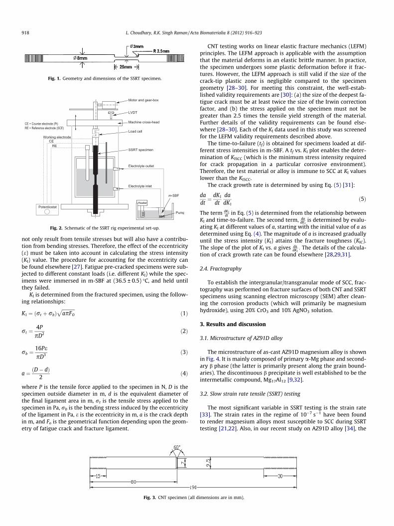
Fig. 1. Geometry and dimensions of the SSRT specimen.
Fig. 2. Schematic of the SSRT rig experimental set-up.
918 L. Choudhary, R.K. Singh Raman / Acta Biomaterialia 8 (2012) 916–923
not only result from tensile stresses but will also have a contribu-tion from bending stresses. Therefore, the effect of the eccentricity(e) must be taken into account in calculating the stress intensity(KI) value. The procedure for accounting for the eccentricity canbe found elsewhere [27]. Fatigue pre-cracked specimens were sub-jected to different constant loads (i.e. different KI) while the spec-imens were immersed in m-SBF at (36.5 ± 0.5) �C, and held untilthey failed.
KI is determined from the fractured specimen, using the follow-ing relationships:
K I ¼ ðrt þ rbÞffiffiffiffiffiffiffiffiffiffiffiapFO
pð1Þ
rt ¼4P
pD2 ð2Þ
rb ¼16PepD3 ð3Þ
a ¼ ðD� dÞ2
ð4Þ
where P is the tensile force applied to the specimen in N, D is thespecimen outside diameter in m, d is the equivalent diameter ofthe final ligament area in m, rt is the tensile stress applied to thespecimen in Pa, rb is the bending stress induced by the eccentricityof the ligament in Pa, e is the eccentricity in m, a is the crack depthin m, and Fo is the geometrical function depending upon the geom-etry of fatigue crack and fracture ligament.
Fig. 3. CNT specimen (all d
CNT testing works on linear elastic fracture mechanics (LEFM)principles. The LEFM approach is applicable with the assumptionthat the material deforms in an elastic brittle manner. In practice,the specimen undergoes some plastic deformation before it frac-tures. However, the LEFM approach is still valid if the size of thecrack-tip plastic zone is negligible compared to the specimengeometry [28–30]. For meeting this constraint, the well-estab-lished validity requirements are [30]: (a) the size of the deepest fa-tigue crack must be at least twice the size of the Irwin correctionfactor, and (b) the stress applied on the specimen must not begreater than 2.5 times the tensile yield strength of the material.Further details of the validity requirements can be found else-where [28–30]. Each of the KI data used in this study was screenedfor the LEFM validity requirements described above.
The time-to-failure (tf) is obtained for specimens loaded at dif-ferent stress intensities in m-SBF. A tf vs. KI plot enables the deter-mination of KISCC (which is the minimum stress intensity requiredfor crack propagation in a particular corrosive environment).Therefore, the test material or alloy is immune to SCC at KI valueslower than the KISCC.
The crack growth rate is determined by using Eq. (5) [31]:
dadt¼ dK I
dtdadK I
ð5Þ
The term dKIdt in Eq. (5) is determined from the relationship between
KI and time-to-failure. The second term, dadKI
is determined by evalu-ating KI at different values of a, starting with the initial value of a asdetermined using Eq. (4). The magnitude of a is increased graduallyuntil the stress intensity (KI) attains the fracture toughness (KIC).The slope of the plot of KI vs. a gives da
dKI: The details of the calcula-
tion of crack growth rate can be found elsewhere [28,29,31].
2.4. Fractography
To establish the intergranular/transgranular mode of SCC, frac-tography was performed on fracture surfaces of both CNT and SSRTspecimens using scanning electron microscopy (SEM) after clean-ing the corrosion products (which will primarily be magnesiumhydroxide), using 20% CrO3 and 10% AgNO3 solution.
3. Results and discussion
3.1. Microstructure of AZ91D alloy
The microstructure of as-cast AZ91D magnesium alloy is shownin Fig. 4. It is mainly composed of primary a-Mg phase and second-ary b phase (the latter is primarily present along the grain bound-aries). The discontinuous b precipitate is well established to be theintermetallic compound, Mg17Al12 [9,32].
3.2. Slow strain rate tensile (SSRT) testing
The most significant variable in SSRT testing is the strain rate[33]. The strain rates in the regime of 10�7 s�1 have been foundto render magnesium alloys most susceptible to SCC during SSRTtesting [21,22]. Also, in our recent study on AZ91D alloy [34], the
imensions are in mm).
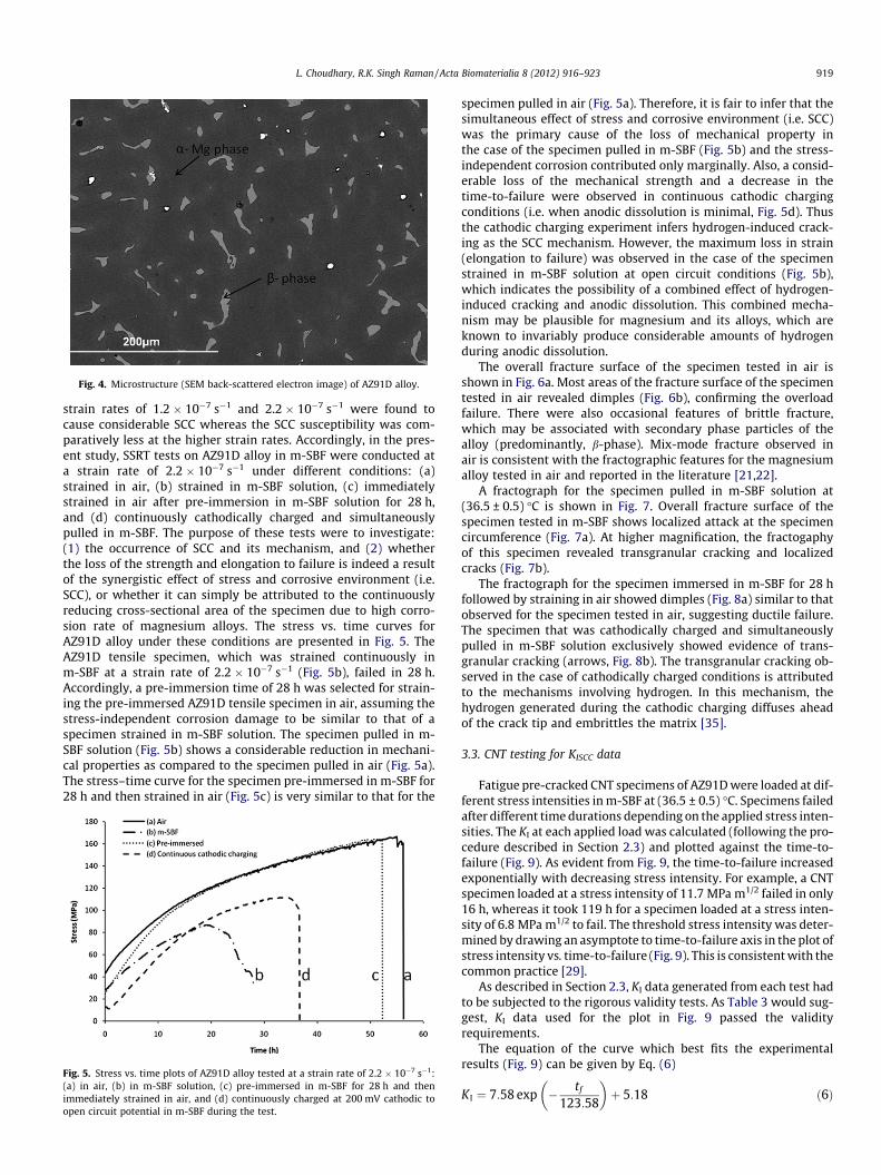
Fig. 4. Microstructure (SEM back-scattered electron image) of AZ91D alloy.
L. Choudhary, R.K. Singh Raman / Acta Biomaterialia 8 (2012) 916–923 919
strain rates of 1.2 � 10�7 s�1 and 2.2 � 10�7 s�1 were found tocause considerable SCC whereas the SCC susceptibility was com-paratively less at the higher strain rates. Accordingly, in the pres-ent study, SSRT tests on AZ91D alloy in m-SBF were conducted ata strain rate of 2.2 � 10�7 s�1 under different conditions: (a)strained in air, (b) strained in m-SBF solution, (c) immediatelystrained in air after pre-immersion in m-SBF solution for 28 h,and (d) continuously cathodically charged and simultaneouslypulled in m-SBF. The purpose of these tests were to investigate:(1) the occurrence of SCC and its mechanism, and (2) whetherthe loss of the strength and elongation to failure is indeed a resultof the synergistic effect of stress and corrosive environment (i.e.SCC), or whether it can simply be attributed to the continuouslyreducing cross-sectional area of the specimen due to high corro-sion rate of magnesium alloys. The stress vs. time curves forAZ91D alloy under these conditions are presented in Fig. 5. TheAZ91D tensile specimen, which was strained continuously inm-SBF at a strain rate of 2.2 � 10�7 s�1 (Fig. 5b), failed in 28 h.Accordingly, a pre-immersion time of 28 h was selected for strain-ing the pre-immersed AZ91D tensile specimen in air, assuming thestress-independent corrosion damage to be similar to that of aspecimen strained in m-SBF solution. The specimen pulled in m-SBF solution (Fig. 5b) shows a considerable reduction in mechani-cal properties as compared to the specimen pulled in air (Fig. 5a).The stress–time curve for the specimen pre-immersed in m-SBF for28 h and then strained in air (Fig. 5c) is very similar to that for the
Fig. 5. Stress vs. time plots of AZ91D alloy tested at a strain rate of 2.2 � 10�7 s�1:(a) in air, (b) in m-SBF solution, (c) pre-immersed in m-SBF for 28 h and thenimmediately strained in air, and (d) continuously charged at 200 mV cathodic toopen circuit potential in m-SBF during the test.
specimen pulled in air (Fig. 5a). Therefore, it is fair to infer that thesimultaneous effect of stress and corrosive environment (i.e. SCC)was the primary cause of the loss of mechanical property inthe case of the specimen pulled in m-SBF (Fig. 5b) and the stress-independent corrosion contributed only marginally. Also, a consid-erable loss of the mechanical strength and a decrease in thetime-to-failure were observed in continuous cathodic chargingconditions (i.e. when anodic dissolution is minimal, Fig. 5d). Thusthe cathodic charging experiment infers hydrogen-induced crack-ing as the SCC mechanism. However, the maximum loss in strain(elongation to failure) was observed in the case of the specimenstrained in m-SBF solution at open circuit conditions (Fig. 5b),which indicates the possibility of a combined effect of hydrogen-induced cracking and anodic dissolution. This combined mecha-nism may be plausible for magnesium and its alloys, which areknown to invariably produce considerable amounts of hydrogenduring anodic dissolution.
The overall fracture surface of the specimen tested in air isshown in Fig. 6a. Most areas of the fracture surface of the specimentested in air revealed dimples (Fig. 6b), confirming the overloadfailure. There were also occasional features of brittle fracture,which may be associated with secondary phase particles of thealloy (predominantly, b-phase). Mix-mode fracture observed inair is consistent with the fractographic features for the magnesiumalloy tested in air and reported in the literature [21,22].
A fractograph for the specimen pulled in m-SBF solution at(36.5 ± 0.5) �C is shown in Fig. 7. Overall fracture surface of thespecimen tested in m-SBF shows localized attack at the specimencircumference (Fig. 7a). At higher magnification, the fractogaphyof this specimen revealed transgranular cracking and localizedcracks (Fig. 7b).
The fractograph for the specimen immersed in m-SBF for 28 hfollowed by straining in air showed dimples (Fig. 8a) similar to thatobserved for the specimen tested in air, suggesting ductile failure.The specimen that was cathodically charged and simultaneouslypulled in m-SBF solution exclusively showed evidence of trans-granular cracking (arrows, Fig. 8b). The transgranular cracking ob-served in the case of cathodically charged conditions is attributedto the mechanisms involving hydrogen. In this mechanism, thehydrogen generated during the cathodic charging diffuses aheadof the crack tip and embrittles the matrix [35].
3.3. CNT testing for KISCC data
Fatigue pre-cracked CNT specimens of AZ91D were loaded at dif-ferent stress intensities in m-SBF at (36.5 ± 0.5) �C. Specimens failedafter different time durations depending on the applied stress inten-sities. The KI at each applied load was calculated (following the pro-cedure described in Section 2.3) and plotted against the time-to-failure (Fig. 9). As evident from Fig. 9, the time-to-failure increasedexponentially with decreasing stress intensity. For example, a CNTspecimen loaded at a stress intensity of 11.7 MPa m1/2 failed in only16 h, whereas it took 119 h for a specimen loaded at a stress inten-sity of 6.8 MPa m1/2 to fail. The threshold stress intensity was deter-mined by drawing an asymptote to time-to-failure axis in the plot ofstress intensity vs. time-to-failure (Fig. 9). This is consistent with thecommon practice [29].
As described in Section 2.3, KI data generated from each test hadto be subjected to the rigorous validity tests. As Table 3 would sug-gest, KI data used for the plot in Fig. 9 passed the validityrequirements.
The equation of the curve which best fits the experimentalresults (Fig. 9) can be given by Eq. (6)
K I ¼ 7:58 exp � tf
123:58
� �þ 5:18 ð6Þ
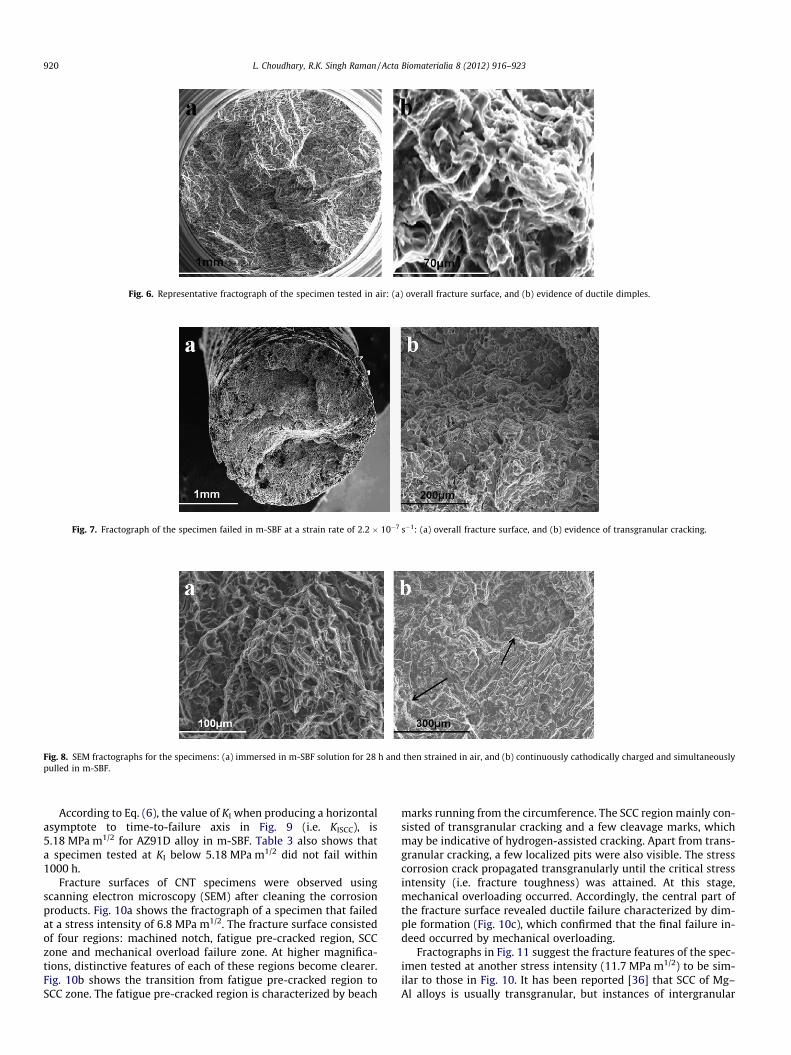
Fig. 6. Representative fractograph of the specimen tested in air: (a) overall fracture surface, and (b) evidence of ductile dimples.
Fig. 7. Fractograph of the specimen failed in m-SBF at a strain rate of 2.2 � 10�7 s�1: (a) overall fracture surface, and (b) evidence of transgranular cracking.
Fig. 8. SEM fractographs for the specimens: (a) immersed in m-SBF solution for 28 h and then strained in air, and (b) continuously cathodically charged and simultaneouslypulled in m-SBF.
920 L. Choudhary, R.K. Singh Raman / Acta Biomaterialia 8 (2012) 916–923
According to Eq. (6), the value of KI when producing a horizontalasymptote to time-to-failure axis in Fig. 9 (i.e. KISCC), is5.18 MPa m1/2 for AZ91D alloy in m-SBF. Table 3 also shows thata specimen tested at KI below 5.18 MPa m1/2 did not fail within1000 h.
Fracture surfaces of CNT specimens were observed usingscanning electron microscopy (SEM) after cleaning the corrosionproducts. Fig. 10a shows the fractograph of a specimen that failedat a stress intensity of 6.8 MPa m1/2. The fracture surface consistedof four regions: machined notch, fatigue pre-cracked region, SCCzone and mechanical overload failure zone. At higher magnifica-tions, distinctive features of each of these regions become clearer.Fig. 10b shows the transition from fatigue pre-cracked region toSCC zone. The fatigue pre-cracked region is characterized by beach
marks running from the circumference. The SCC region mainly con-sisted of transgranular cracking and a few cleavage marks, whichmay be indicative of hydrogen-assisted cracking. Apart from trans-granular cracking, a few localized pits were also visible. The stresscorrosion crack propagated transgranularly until the critical stressintensity (i.e. fracture toughness) was attained. At this stage,mechanical overloading occurred. Accordingly, the central part ofthe fracture surface revealed ductile failure characterized by dim-ple formation (Fig. 10c), which confirmed that the final failure in-deed occurred by mechanical overloading.
Fractographs in Fig. 11 suggest the fracture features of the spec-imen tested at another stress intensity (11.7 MPa m1/2) to be sim-ilar to those in Fig. 10. It has been reported [36] that SCC of Mg–Al alloys is usually transgranular, but instances of intergranular
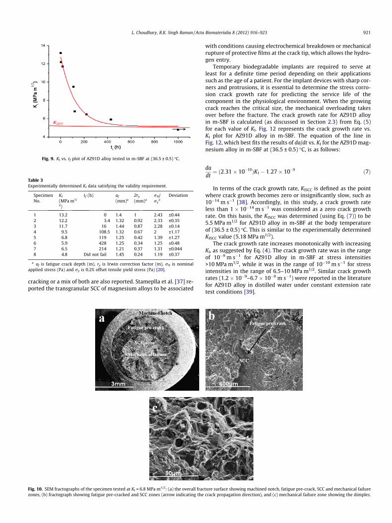
Fig. 9. KI vs. tf plot of AZ91D alloy tested in m-SBF at (36.5 ± 0.5) �C.
Table 3Experimentally determined KI data satisfying the validity requirement.
SpecimenNo.
KI
(MPa m1/
2)
tf (h) af
(mm)a2ry
(mm)arN/ry
aDeviation
1 13.2 0 1.4 1 2.43 ±0.442 12.2 3.4 1.32 0.92 2.33 ±0.353 11.7 16 1.44 0.87 2.28 ±0.144 9.5 108.5 1.32 0.67 2 ±1.175 6.8 119 1.25 0.42 1.39 ±1.276 5.9 428 1.25 0.34 1.25 ±0.487 6.5 214 1.21 0.37 1.31 ±0.0448 4.8 Did not fail 1.45 0.24 1.19 ±0.37
a af is fatigue crack depth (m), ry is Irwin correction factor (m), rN is nominalapplied stress (Pa) and ry is 0.2% offset tensile yield stress (Pa) [20].
L. Choudhary, R.K. Singh Raman / Acta Biomaterialia 8 (2012) 916–923 921
cracking or a mix of both are also reported. Stameplla et al. [37] re-ported the transgranular SCC of magnesium alloys to be associated
Fig. 10. SEM fractographs of the specimen tested at KI = 6.8 MPa m1/2: (a) the overall fraczones, (b) fractograph showing fatigue pre-cracked and SCC zones (arrow indicating the
with conditions causing electrochemical breakdown or mechanicalrupture of protective films at the crack tip, which allows the hydro-gen entry.
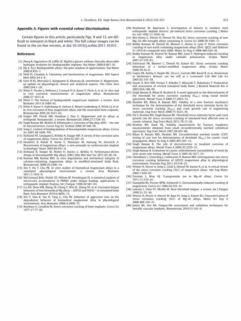
Temporary biodegradable implants are required to serve atleast for a definite time period depending on their applicationssuch as the age of a patient. For the implant devices with sharp cor-ners and protrusions, it is essential to determine the stress corro-sion crack growth rate for predicting the service life of thecomponent in the physiological environment. When the growingcrack reaches the critical size, the mechanical overloading takesover before the fracture. The crack growth rate for AZ91D alloyin m-SBF is calculated (as discussed in Section 2.3) from Eq. (5)for each value of KI. Fig. 12 represents the crack growth rate vs.KI plot for AZ91D alloy in m-SBF. The equation of the line inFig. 12, which best fits the results of da/dt vs. KI for the AZ91D mag-nesium alloy in m-SBF at (36.5 ± 0.5) �C, is as follows:
dadt¼ ð2:31� 10�10ÞK I � 1:27� 10�9 ð7Þ
In terms of the crack growth rate, KISCC is defined as the pointwhere crack growth becomes zero or insignificantly slow, such as10�14 m s�1 [38]. Accordingly, in this study, a crack growth rateless than 1 � 10�14 m s�1 was considered as a zero crack growthrate. On this basis, the KISCC was determined (using Eq. (7)) to be5.5 MPa m1/2 for AZ91D alloy in m-SBF at the body temperatureof (36.5 ± 0.5) �C. This is similar to the experimentally determinedKISCC value (5.18 MPa m1/2).
The crack growth rate increases monotonically with increasingKI, as suggested by Eq. (4). The crack growth rate was in the rangeof 10�9 m s�1 for AZ91D alloy in m-SBF at stress intensities>10 MPa m1/2, while it was in the range of 10�10 m s�1 for stressintensities in the range of 6.5–10 MPa m1/2. Similar crack growthrates (1.2 � 10�9–6.7 � 10�9 m s�1) were reported in the literaturefor AZ91D alloy in distilled water under constant extension ratetest conditions [39].
ture surface showing machined notch, fatigue pre-crack, SCC and mechanical failurecrack propagation direction), and (c) mechanical failure zone showing the dimples.
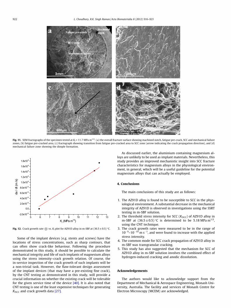
Fig. 11. SEM fractographs of the specimen tested at KI = 11.7 MPa m1/2: (a) the overall fracture surface showing machined notch, fatigue pre-crack, SCC and mechanical failurezones, (b) fatigue pre-cracked area, (c) fractograph showing transition from fatigue pre-cracked area to SCC zone (arrow indicating the crack propagation direction), and (d)mechanical failure zone showing the dimple formation.
5 6 7 8 9 10 11 12 13-2.0x10⁻¹⁰
0.0
2.0x10⁻¹⁰
4.0x10⁻¹⁰
6.0x10⁻¹⁰
8.0x10⁻¹⁰
1.0x10⁻⁹
1.2x10⁻⁹
1.4x10⁻⁹
1.6x10⁻⁹
1.8x10⁻⁹
da /
dt (m
/s)
KI (MPa m1/2)
Fig. 12. Crack growth rate ðdadtÞ vs. KI plot for AZ91D alloy in m-SBF at (36.5 ± 0.5) �C.
922 L. Choudhary, R.K. Singh Raman / Acta Biomaterialia 8 (2012) 916–923
Some of the implant devices (e.g. stents and screws) have thelocations of stress concentrations, such as sharp contours, thatcan often show crack-like behaviour. Following the proceduredemonstrated in this study, it should be possible to calculate themechanical integrity and life of such implants of magnesium alloysusing the stress intensity–crack growth relation. Of course, thein-service inspection of the crack growth of such implants will bea non-trivial task. However, the flaw-tolerant design assessmentof the implant devices (that may have a pre-existing fine crack),by the CNT testing as demonstrated in this study, will provide acrucial information on whether the existing crack will be tolerablefor the given service time of the device [40]. It is also noted thatCNT testing is one of the least expensive techniques for generatingKISCC and crack growth data [27].
As discussed earlier, the aluminium containing magnesium al-loys are unlikely to be used as implant materials. Nevertheless, thisstudy provides an improved mechanistic insight into SCC fracturecharacteristics for magnesium alloys in the physiological environ-ment, in general, which will be a useful guideline for the potentialmagnesium alloys that can actually be employed.
4. Conclusions
The main conclusions of this study are as follows:
1. The AZ91D alloy is found to be susceptible to SCC in the phys-iological environment. A substantial decrease in the mechanicalintegrity of AZ91D is observed in investigations using the SSRTtesting in m-SBF solution.
2. The threshold stress intensity for SCC (KISCC) of AZ91D alloy inm-SBF at (36.5 ± 0.5) �C is determined to be 5.18 MPa m1/2,using the CNT technique.
3. The crack growth rates were measured to be in the range of10�9–10�10 m s�1, and were found to increase with the appliedstress intensity.
4. The common mode for SCC crack propagation of AZ91D alloy inm-SBF was transgranular cracking.
5. This study has also suggested that the mechanism for SCC ofAZ91D alloy in m-SBF solution involves the combined effect ofhydrogen-induced cracking and anodic dissolution.
Acknowledgements
The authors would like to acknowledge support from theDepartment of Mechanical & Aerospace Engineering, Monash Uni-versity, Australia. The facility and services of Monash Centre forElectron Microscopy (MCEM) are acknowledged.
L. Choudhary, R.K. Singh Raman / Acta Biomaterialia 8 (2012) 916–923 923
Appendix A. Figures with essential colour discrimination
Certain figures in this article, particularly Figs. 9 and 12, are dif-ficult to interpret in black and white. The full colour images can befound in the on-line version, at doi:10.1016/j.actbio.2011.10.031.
References
[1] Zberg B, Uggowitzer PJ, Loffler JF. MgZnCa glasses without clinically observablehydrogen evolution for biodegradable implants. Nat Mater 2009;8:887–91.
[2] Ma E, Xu J. Biodegradable alloys: the glass window of opportunities. Nat Mater2009;8:855–7.
[3] Wolf FI, Cittadini A. Chemistry and biochemistry of magnesium. Mol AspectMed 2003;24:3–9.
[4] Saris N-EL, Mervaala E, Karppanen H, Khawaja JA, Lewenstam A. Magnesium:an update on physiological, clinical and analytical aspects. Clin Chim Acta2000;294:1–26.
[5] Witte F, Fischer J, Nellesen J, Crostack H-A, Kaese V, Pisch A, et al. In vitro andin vivo corrosion measurements of magnesium alloys. Biomaterials2006;27:1013–8.
[6] Witte F. The history of biodegradable magnesium implants: a review. ActaBiomater 2011;6:1680–92.
[7] Witte F, Kaese V, Haferkamp H, Switzer E, Meyer-Lindenberg A, Wirth CJ, et al.In vivo corrosion of four magnesium alloys and the associated bone response.Biomaterials 2005;26:3557–63.
[8] Staiger MP, Pietak AM, Huadmai J, Dias G. Magnesium and its alloys asorthopedic biomaterials: a review. Biomaterials 2006;27:1728–34.
[9] Singh Raman RK, Birbilis N, Efthimiadis J. Corrosion of Mg alloy AZ91 – the roleof microstructure. Corros Eng Sci Technol 2004;39:346–50.
[10] Song G. Control of biodegradation of biocompatable magnesium alloys. CorrosSci 2007;49:1696–701.
[11] Kirkland NT, Lespagnol J, Birbilis N, Staiger MP. A survey of bio-corrosion ratesof magnesium alloys. Corros Sci 2010;52:287–91.
[12] Heublein B, Rohde R, Kaese V, Niemeyer M, Hartung W, Haverich A.Biocorrosion of magnesium alloys: a new principle in cardiovascular implanttechnology? Heart 2003;89:651–6.
[13] Kirkland N, Staiger M, Nisbet D, Davies C, Birbilis N. Performance-drivendesign of biocompatible Mg alloys. JOM J Min Met Mat Soc 2011;63:28–34.
[14] Kannan MB, Raman RKS. In vitro degradation and mechanical integrity ofcalcium-containing magnesium alloys in modified-simulated body fluid.Biomaterials 2008;29:2306–14.
[15] Xin Y, Hu T, Chu PK. In vitro studies of biomedical magnesium alloys in asimulated physiological environment: a review. Acta Biomater2011;7:1452–9.
[16] McCormack BAO, Walsh CD, Wilson SP, Prendergast PJ. A statistical analysis ofmicrocrack accumulation in PMMA under fatigue loading: applications toorthopaedic implant fixation. Int J Fatigue 1998;20:581–93.
[17] Gu XN, Zhou WR, Zheng YF, Cheng Y, Wei SC, Zhong SP, et al. Corrosion fatiguebehaviors of two biomedical Mg alloys – AZ91D and WE43 – in simulated bodyfluid. Acta Biomater 2010;6:4605–13.
[18] Xin Y, Huo K, Tao H, Tang G, Chu PK. Influence of aggressive ions on thedegradation behavior of biomedical magnesium alloy in physiologicalenvironment. Acta Biomater 2008;4:2008–15.
[19] Bombara G, Cavallini M. Stress corrosion cracking of bone implants. Corros Sci1977;17:77–85.
[20] Sivakumar M, Rajeswari S. Investigation of failures in stainless steelorthopaedic implant devices: pit-induced stress corrosion cracking. J MaterSci Lett 1992;11:1039–42.
[21] Ben-Hamu G, Eliezer D, Dietzel W, Shin KS. Stress corrosion cracking of newMg–Zn–Mn wrought alloys containing Si. Corros Sci 2008;50:1505–17.
[22] Bobby Kannan M, Dietzel W, Blawert C, Atrens A, Lyon P. Stress corrosioncracking of rare-earth containing magnesium alloys ZE41, QE22 and Elektron21 (EV31A) compared with AZ80. Mater Sci Eng A 2008;480:529–39.
[23] Bobby Kannan M, Dietzel W, Raman RKS, Lyon P. Hydrogen-induced-crackingin magnesium alloy under cathodic polarization. Scripta Mater2007;57:579–81.
[24] Srinivasan PB, Blawert C, Dietzel W, Kainer KU. Stress corrosion crackingbehaviour of a surface-modified magnesium alloy. Scripta Mater2008;59:43–6.
[25] Gupta VB, Anitha S, Hegde ML, Zecca L, Garruto RM, Ravid R, et al. Aluminiumin Alzheimer’s disease: are we still at a crossroad? Cell Mol Life Sci2005;62:143–58.
[26] Oyane A, Kim HM, Furuya T, Kokubo T, Miyazaki T, Nakamura T. Preparationand assessment of revised simulated body fluids. J Biomed Material Res A2003;65A:188–95.
[27] Singh Raman R, Rihan R, Ibrahim R. A novel approach to the determination ofthe threshold for stress corrosion cracking (KISCC) using round tensilespecimens. Metall Trans A 2006;37:2963–73.
[28] Ibrahim RN, Rihan R, Raman RKS. Validity of a new fracture mechanicstechnique for the determination of the threshold stress intensity factor forstress corrosion cracking (KISCC) and crack growth rate of engineeringmaterials. Eng Fract Mech 2008;75:1623–34.
[29] Pal S, Ibrahim RN, Singh Raman RK. Threshold stress intensity factor and crackgrowth rate for stress corrosion cracking of simulated heat affected zone incaustic solution. Eng Fract Mech 2011;78:13–26.
[30] Ibrahim RN, Stark HL. Validity requirements for fracture toughnessmeasurements obtained from small circumferentially notched cylindricalspecimens. Eng Fract Mech 1987;28:455–60.
[31] Rihan R, Raman RKS, Ibrahim RN. Circumferential notched tensile (CNT)testing of cast iron for determination of threshold (KISCC) for caustic crackpropagation. Mater Sci Eng A 2005;407:207–12.
[32] Singh Raman R. The role of microstructure in localized corrosion ofmagnesium alloys. Metall Trans A 2004;35:2525–31.
[33] Singh Raman R. Evaluation of caustic embrittlement susceptibility of steels byslow strain rate testing. Metall Trans A 2005;36:1817–23.
[34] Choudhary L, Szmerling J, Goldwasser R, Raman RKS. Investigations into stresscorrosion cracking behaviour of AZ91D magnesium alloy in physiologicalenvironment. Procedia Eng 2011;10:518–23.
[35] Winzer N, Atrens A, Song G, Ghali E, Dietzel W, Kainer K, et al. A critical reviewof the stress corrosion cracking (SCC) of magnesium alloys. Adv Eng Mater2005;7:659–93.
[36] Fairman L, Bray HJ. Transgranular see in Mg–Al alloys. Corros Sci1971;11:533–41.
[37] Stampella RS, Procter RPM, Ashworth V. Environmentally-induced cracking ofmagnesium. Corros Sci 1984;24:325–41.
[38] Lawson L, Chen EY, Meshii M. Near-threshold fatigue: a review. Int J Fatigue1999;21:15–34.
[39] Winzer N, Atrens A, Dietzel W, Raja VS, Song G, Kainer KU. Characterisation ofstress corrosion cracking (SCC) of Mg–Al alloys. Mater Sci Eng A2008;488:339–51.
[40] James BA, Sire RA. Fatigue-life assessment and validation techniques formetallic vascular implants. Biomaterials 2010;31:181–6.