Embed Size (px)
Citation preview
Lu LuMem. ASME
Department of Mechanical and
Industrial Engineering,
University of Illinois at Chicago,
842 W Taylor Street, ERF 1076,
Chicago, IL 60607
e-mail: [email protected]
Ping GuoMem. ASME
Department of Mechanical
and Automation Engineering,
The Chinese University of Hong Kong,
Hong Kong, China
Yayue Pan1
Mem. ASME
Department of Mechanical and
Industrial Engineering,
University of Illinois at Chicago,
842 W Taylor Street, ERF 3025,
Chicago, IL 60607
e-mail: [email protected]
Magnetic-Field-AssistedProjection Stereolithography forThree-Dimensional Printing ofSmart StructuresIn this paper, an additive manufacturing (AM) process, magnetic field-assisted projectionstereolithography (M-PSL), is developed for 3D printing of three-dimensional (3D) smartpolymer composites. The 3D-printed magnetic field-responsive smart polymer compositecreates a wide range of motions, opening up possibilities for various new applications,like sensing and actuation in soft robotics, biomedical devices, and autonomous systems.In the proposed M-PSL process, a certain amount of nano- or microsized ferromagneticparticles is deposited in liquid polymer by using a programmable microdeposition nozzle.An external magnetic field is applied to direct the magnetic particles to the desired posi-tion and to form the desired orientation and patterns. After that, a digital mask image isused to cure particles in photopolymer with desired distribution patterns. The magnetic-field-assisted projection stereolithography (M-PSL) manufacturing process planning,testbed, and materials are discussed. Three test cases, an impeller, a two-wheel roller,and a flexible film, were performed to verify and validate the feasibility and effectivenessof the proposed process. They were successfully fabricated and remote controls of theprinted samples were demonstrated, showing the capability of printed smart polymercomposites on performing desired functions. [DOI: 10.1115/1.4035964]
1 Introduction
Materials with properties engineered to change in a controlledand desired fashion with specific external stimuli, like an externalvoltage, a magnetic field, a change in pH, a stress change, a tem-perature change, a moisture change, or a change in concentrationof chemical species, are called smart materials and have receivedwide attentions recently [1]. This paper is focused on magneticfield-responsive smart polymer composites. A number of strikingphenomena can be produced by embedding magnetic particlesinto polymer with designed patterns, including tunable elasticproperties, giant deformational effects, high elasticity, anisotropicelastic and swelling properties, and quick response to magneticfields [2]. In particular, composites that show anisotropic behaviorin terms of mechanical and magnetic properties could be used tocreate a wide range of motions, and to control the shape changeand movements. It opens up possibilities for various new techno-logical applications in several biomedical and industrial fields,e.g., controlled drug delivery systems, diagnostic medicine,muscle-like soft linear actuators, biomimetic devices, separationtechniques, high-density memory devices, spintronic, actuatorsfor robots, elastomer bearings, and vibration absorbers to name afew [3–11].
However, manufacturing of such smart polymer compositesthat possess intelligence at the material level is still challenging.Material intelligence is referring to three main functions: sensingchanges in environmental conditions, processing the sensed infor-mation, and finally actuating by moving away from or to the stim-ulus [1,2]. Conventional manufacturing technologies for smartpolymer composite products include wet lay-up, resin transfermolding (RTM), autoclave processing, resin film infusion, fila-ment winding, prepreg method, etc., [7]. Despite advancements
and efforts in polymer composite manufacturing in last two deca-des, a number of issues such as 3D part production, heterogeneouscomposites fabrication, intensive labor, and so on, stillexist [7,12].
Additive manufacturing (AM), which is also known as 3Dprinting or solid freeform fabrication, is a class of technologiesthat builds parts layer by layer using digital 3D design data. Com-paring with the traditional manufacturing technologies, AM offersmany unique advantages in terms of material/energy efficiency,mold-free operation style, design flexibility, and so on [13]. In lastdecade, many efforts have been made on developing AM technol-ogies for polymer composites fabrication. For example, Khalilet al. [14] presented a multinozzle deposition system to 3D printpolymer composite, and Zhou et al. [15] developed a multimate-rial mask-image-projection-based stereolithography (SL) systemthat is capable of curing multiple liquid resins in a build job toproduce multipolymer materials. Furthermore, Beaman and Dasgroups investigated selective laser sintering for polymer compos-ite fabrication using multiple polymer powder materials [16–19].
As a multiscale and fast additive manufacturing method, stereo-lithography (SL) related processes have also been developed toprocess a mixture of metallic/polymer particles and liquid[20–22]. In the process of 3D printing particle–polymer compo-sites using SL-related technologies, the printing job usually startswith mixing the filler particles with liquid photopolymers byvarious methods like ultrasonic mixing. Then, the mixture is poly-merized by a laser beam or patterned light in a layer-by-layerfashion. Such SL methods open new routes for fabricating various3D ceramic products or smart polymer composite parts withhomogeneous properties. Compared with other AM technologies,SL methods provide multiple scale manufacturing capabilitiesfrom nanoscale to meso-scale [23,24], smooth surface [25,26],and fast build speed [27,28]. However, mixing of particles andliquid resin remains the primary challenge, as agglomeration orundesired particle dispersion patterns occur when the particles arenot blended properly before the printing or when the 3D printing
1Corresponding author.Manuscript received November 7, 2016; final manuscript received February 2,
2017; published online March 8, 2017. Assoc. Editor: Zhijian J. Pei.
Journal of Manufacturing Science and Engineering JULY 2017, Vol. 139 / 071008-1Copyright VC 2017 by ASME
Downloaded From: https://manufacturingscience.asmedigitalcollection.asme.org on 08/05/2019 Terms of Use: http://www.asme.org/about-asme/terms-of-use
process takes a long time. Furthermore, because a whole tank ofparticle-resin suspension is prepared and is used for printinglayers, the particle concentrations, and filling patterns are hardlyto control among layers in a single print. Compared with the insitu particle-resin blending, such premixing manufacturingmethod lacks flexibilities in producing composites with heteroge-neous properties, greatly limiting applications in smart machines.
Therefore, in this paper, we developed a magnetic field-assistedprojection stereolithography (M-PSL) process, characterized by alayer-by-layer in situ particle resin mixing, and hence heterogene-ous composite properties. With the assistance of an external mag-netic field, it is possible to control local dispersions of magneticparticles in liquid photopolymer, and hence to fabricate materialintelligence by patterning particles and localizing particle concen-trations in the polymer matrix. The manufacturing process hasbeen planned, and a testbed was developed. Three test cases werefabricated and discussed. The experimental results verified thefeasibility of the fabricating magnetic field responsive smartpolymer composites using the proposed method.
2 M-PSL Process Planning
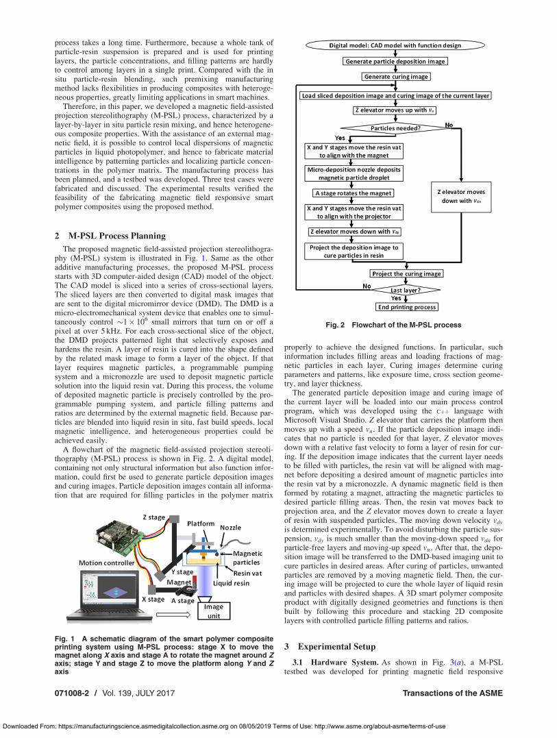
The proposed magnetic field-assisted projection stereolithogra-phy (M-PSL) system is illustrated in Fig. 1. Same as the otheradditive manufacturing processes, the proposed M-PSL processstarts with 3D computer-aided design (CAD) model of the object.The CAD model is sliced into a series of cross-sectional layers.The sliced layers are then converted to digital mask images thatare sent to the digital micromirror device (DMD). The DMD is amicro-electromechanical system device that enables one to simul-taneously control �1� 106 small mirrors that turn on or off apixel at over 5 kHz. For each cross-sectional slice of the object,the DMD projects patterned light that selectively exposes andhardens the resin. A layer of resin is cured into the shape definedby the related mask image to form a layer of the object. If thatlayer requires magnetic particles, a programmable pumpingsystem and a micronozzle are used to deposit magnetic particlesolution into the liquid resin vat. During this process, the volumeof deposited magnetic particle is precisely controlled by the pro-grammable pumping system, and particle filling patterns andratios are determined by the external magnetic field. Because par-ticles are blended into liquid resin in situ, fast build speeds, localmagnetic intelligence, and heterogeneous properties could beachieved easily.
A flowchart of the magnetic field-assisted projection stereoli-thography (M-PSL) process is shown in Fig. 2. A digital model,containing not only structural information but also function infor-mation, could first be used to generate particle deposition imagesand curing images. Particle deposition images contain all informa-tion that are required for filling particles in the polymer matrix
properly to achieve the designed functions. In particular, suchinformation includes filling areas and loading fractions of mag-netic particles in each layer. Curing images determine curingparameters and patterns, like exposure time, cross section geome-try, and layer thickness.
The generated particle deposition image and curing image ofthe current layer will be loaded into our main process controlprogram, which was developed using the Cþþ language withMicrosoft Visual Studio. Z elevator that carries the platform thenmoves up with a speed vu. If the particle deposition image indi-cates that no particle is needed for that layer, Z elevator movesdown with a relative fast velocity to form a layer of resin for cur-ing. If the deposition image indicates that the current layer needsto be filled with particles, the resin vat will be aligned with mag-net before depositing a desired amount of magnetic particles intothe resin vat by a micronozzle. A dynamic magnetic field is thenformed by rotating a magnet, attracting the magnetic particles todesired particle filling areas. Then, the resin vat moves back toprojection area, and the Z elevator moves down to create a layerof resin with suspended particles. The moving down velocity vdy
is determined experimentally. To avoid disturbing the particle sus-pension, vdy is much smaller than the moving-down speed vdn forparticle-free layers and moving-up speed vu. After that, the depo-sition image will be transferred to the DMD-based imaging unit tocure particles in desired areas. After curing of particles, unwantedparticles are removed by a moving magnetic field. Then, the cur-ing image will be projected to cure the whole layer of liquid resinand particles with desired shapes. A 3D smart polymer compositeproduct with digitally designed geometries and functions is thenbuilt by following this procedure and stacking 2D compositelayers with controlled particle filling patterns and ratios.
3 Experimental Setup
3.1 Hardware System. As shown in Fig. 3(a), a M-PSLtestbed was developed for printing magnetic field responsive
Fig. 1 A schematic diagram of the smart polymer compositeprinting system using M-PSL process: stage X to move themagnet along X axis and stage A to rotate the magnet around Zaxis; stage Y and stage Z to move the platform along Y and Zaxis
Fig. 2 Flowchart of the M-PSL process
071008-2 / Vol. 139, JULY 2017 Transactions of the ASME
Downloaded From: https://manufacturingscience.asmedigitalcollection.asme.org on 08/05/2019 Terms of Use: http://www.asme.org/about-asme/terms-of-use
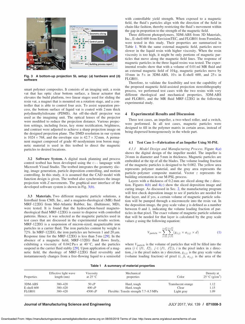
smart polymer composites. It consists of an imaging unit, a resinvat that has optic clear bottom surface, a linear actuator thatelevates the build platform, two linear stages used for sliding theresin vat, a magnet that is mounted on a rotation stage, and a con-troller that is able to control four axis. To assist separation pro-cess, the bottom surface of liquid vat is coated with 2 mm thickpolydimethylsiloxane (PDMS). An off-the-shelf projector wasused as the imagining unit. The optical lenses of the projectorwere modified to reduce the projection distance. Various projec-tion settings, including focus, key stone rectification, brightness,and contrast were adjusted to achieve a sharp projection image onthe designed projection plane. The DMD resolution in our systemis 1024� 768, and the envelope size is 42.7� 32 mm. A perma-nent magnet composed of grade 40 neodymium iron boron mag-netic material is used in this testbed to direct the magneticparticles to desired locations.
3.2 Software System. A digital mask planning and processcontrol testbed has been developed using the Cþþ language withMicrosoft Visual Studio. The testbed integrates the geometry slic-ing, image generation, particle deposition controlling, and motioncontrolling. In this study, it is assumed that the CAD model withfunction design is given. The testbed also synchronizes the imageprojection with Z movements. The graphical user interface of thedeveloped software system is shown in Fig. 3(b).
3.3 Materials. Two different magnetic particle solutions, aferrofluid from CMS, Inc., and a magneto-rheological (MR) fluidMRF-122EG from Mid-Atlantic Rubber, Inc. (Baltimore, MD),were tested. It is found that the hydrocarbon-based magneto-rheological fluid MRF-122EG is easier to disperse with controlledpatterns. Hence, it was selected as the magnetic particles used intest cases that are discussed in the experimental results section.MRF-122EG is a suspension of micron-sized, magnetizable ironparticles in a carrier fluid. The iron particles content by weight is72%. In MRF-122EG, the iron particles are between 1 and 20 lm.Response time for the MRF-122EG is less than 5 ms [29]. In theabsence of a magnetic field, MRF-132EG fluid flows freely,exhibiting a viscosity of 0.042 Pa�s at 40 �C, and the particlessuspend in the carrier fluid stably [29]. Upon application of a mag-netic field, the rheology of MRF-122EG fluid reversibly andinstantaneously changes from a free-flowing liquid to a semisolid
with controllable yield strength. When exposed to a magneticfield, the fluid’s particles align with the direction of the field inchain-like fashion, thereby restricting the fluid’s movement withinthe gap in proportion to the strength of the magnetic field.
Three different photopolymers, 3DM-ABS from 3D Materials,Inc., E-shell 600 from EnvisionTEC, and FLGR01 from Formlabs,were tested in this study. Their properties are summarized inTable 1. With the same external magnetic field, particles moveslower in the liquid resin with higher viscosity. When the resinviscosity is too high, it might be only portions of magnetic par-ticles that move along the magnetic field lines. The response ofmagnetic particles in the three liquid resins was tested. The exper-imental results show that with a volume of 0.01 ml MR fluid andan external magnetic field of 10 kg, magnetic particles move by10 mm in 5 s in 3DM-ABS, 10 s in E-shell 600, and 25 s inFLGR01.
Therefore, to validate the feasibility and test the capability ofthe proposed magnetic field-assisted projection stereolithographyprocess, we performed test cases with the two resins with verydifferent rheological and mechanical properties, 3DM-ABSand FLGR01, and the MR fluid MRF-122EG in the followingexperimental study.
4 Experimental Results and Discussion
Three test cases, an impeller, a two-wheel roller, and a switch,were performed. In all test cases, magnetic particles weredesigned to fill in the polymer matrix in certain areas, instead ofbeing dispersed homogeneously in the whole part.
4.1 Test Case 1—Fabrication of an Impeller Using M-PSL
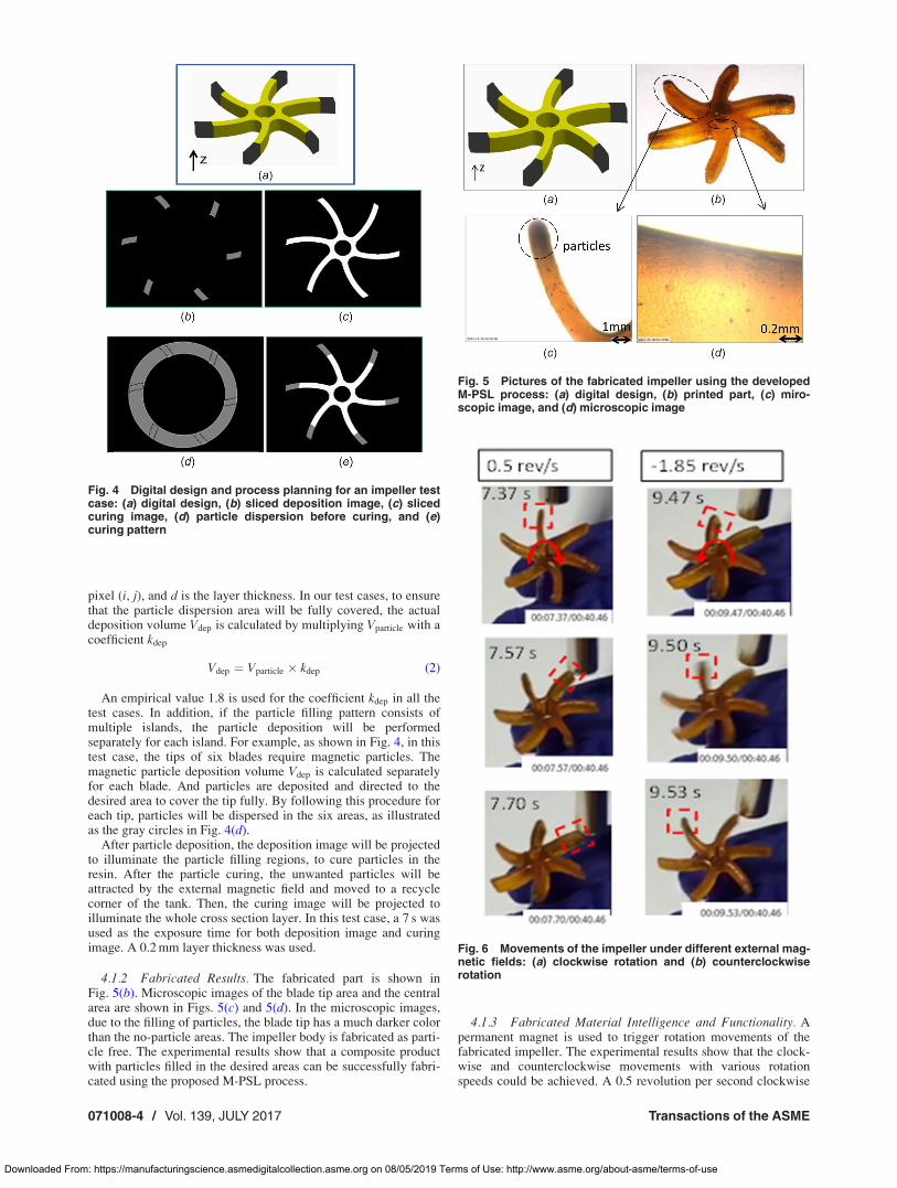
4.1.1 Model Design and Manufacturing Process. Figure 4(a)shows the digital design of the impeller model. The impeller is24 mm in diameter and 5 mm in thickness. Magnetic particles areembedded at the tip of all the blades. The volume loading fractionof the magnetic particles is designed to be 0.002. The yellow arearepresents polymer material, and the gray area represents theparticle–polymer composite material. Vector z represents thebuilding orientation in our M-PSL process.
Layers with a thickness of 0.2 mm are sliced along the z direc-tion. Figures 4(b) and 4(c) show the sliced deposition image andcuring image. As discussed in Sec. 2, the manufacturing programwill first check deposition image to see if particles are needed forthat layer, and if yes, a certain volume of magnetic particle solu-tion will be pumped through a micronozzle into the resin vat. Inthe deposition image, the gray scale value g is defined as a numberbetween 0 and 1, indicating the volume loading fraction of par-ticles in that pixel. The exact volume of magnetic particle solutionthat will be needed for that layer is calculated by the gray scalevalues g using the following equation:
Vparticle ¼Xi¼I2
i¼I1
Xj¼J2
j¼J1
ðgði;jÞ � aði;jÞ � dÞ (1)
where Vparticle is the volume of particles that will be filled into thearea ði 2 ðI1; I2Þ; j 2 ðJ1; J2Þ), i is the pixel index in x direc-tion, j is the pixel index in y direction, gði;jÞ is the gray scale value(volume loading fraction) of pixel (i, j), aði;jÞ is the area of the
Fig. 3 A bottom-up projection SL setup: (a) hardware and (b)software
Table 1 A summary of material properties
PropertiesEffective light wave
length (nm)Viscosityat 25 �C
Mechanicalproperties Color
Density at25 �C (g/cm3)
3DM-ABS 380–420 50 cP Hard, tough Translucent orange 1.12E-shell 600 380–420 400 cP Hard, tough Clear 1.15FLGR01 380–420 4500 cP Flexible: Tensile strength 7.7–8.5 MPa Light gray 1.09
Journal of Manufacturing Science and Engineering JULY 2017, Vol. 139 / 071008-3
Downloaded From: https://manufacturingscience.asmedigitalcollection.asme.org on 08/05/2019 Terms of Use: http://www.asme.org/about-asme/terms-of-use
pixel (i, j), and d is the layer thickness. In our test cases, to ensurethat the particle dispersion area will be fully covered, the actualdeposition volume Vdep is calculated by multiplying Vparticle with acoefficient kdep
Vdep ¼ Vparticle � kdep (2)
An empirical value 1.8 is used for the coefficient kdep in all thetest cases. In addition, if the particle filling pattern consists ofmultiple islands, the particle deposition will be performedseparately for each island. For example, as shown in Fig. 4, in thistest case, the tips of six blades require magnetic particles. Themagnetic particle deposition volume Vdep is calculated separatelyfor each blade. And particles are deposited and directed to thedesired area to cover the tip fully. By following this procedure foreach tip, particles will be dispersed in the six areas, as illustratedas the gray circles in Fig. 4(d).
After particle deposition, the deposition image will be projectedto illuminate the particle filling regions, to cure particles in theresin. After the particle curing, the unwanted particles will beattracted by the external magnetic field and moved to a recyclecorner of the tank. Then, the curing image will be projected toilluminate the whole cross section layer. In this test case, a 7 s wasused as the exposure time for both deposition image and curingimage. A 0.2 mm layer thickness was used.
4.1.2 Fabricated Results. The fabricated part is shown inFig. 5(b). Microscopic images of the blade tip area and the centralarea are shown in Figs. 5(c) and 5(d). In the microscopic images,due to the filling of particles, the blade tip has a much darker colorthan the no-particle areas. The impeller body is fabricated as parti-cle free. The experimental results show that a composite productwith particles filled in the desired areas can be successfully fabri-cated using the proposed M-PSL process.
4.1.3 Fabricated Material Intelligence and Functionality. Apermanent magnet is used to trigger rotation movements of thefabricated impeller. The experimental results show that the clock-wise and counterclockwise movements with various rotationspeeds could be achieved. A 0.5 revolution per second clockwise
Fig. 4 Digital design and process planning for an impeller testcase: (a) digital design, (b) sliced deposition image, (c) slicedcuring image, (d) particle dispersion before curing, and (e)curing pattern
Fig. 5 Pictures of the fabricated impeller using the developedM-PSL process: (a) digital design, (b) printed part, (c) miro-scopic image, and (d) microscopic image
Fig. 6 Movements of the impeller under different external mag-netic fields: (a) clockwise rotation and (b) counterclockwiserotation
071008-4 / Vol. 139, JULY 2017 Transactions of the ASME
Downloaded From: https://manufacturingscience.asmedigitalcollection.asme.org on 08/05/2019 Terms of Use: http://www.asme.org/about-asme/terms-of-use
rotation example and a �1.85 revolution per second counterclock-wise rotation example are shown in Fig. 6. For presentationeffects, a red dashed block marks the same blade in all pictures toshow rotation movements, and a red arrow is used to denote therotation direction of each movement.
Experiments were performed to characterize the rotation accu-racy of the impeller. Five replications were conducted. A camerawas mounted in a way that top images of the rotating impellercould be taken. The rotation angle of the impeller was calculatedby analyzing the captured top images and compared with thedesigned rotation angle. It was found that a rotation accuracy withan error of 0.05% 6 0.03% can be achieved on the printedimpeller.
4.2 Test Case 2—Fabrication of a Two-Wheel RollerUsing M-PSL
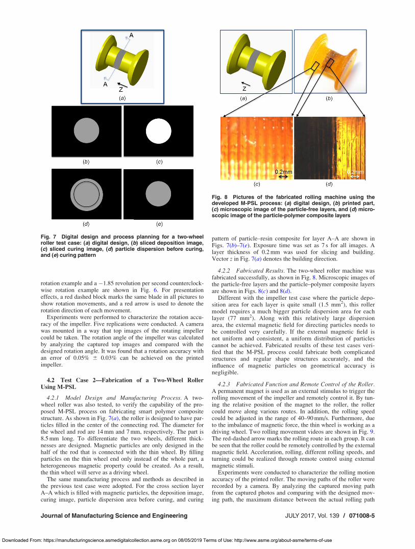
4.2.1 Model Design and Manufacturing Process. A two-wheel roller was also tested, to verify the capability of the pro-posed M-PSL process on fabricating smart polymer compositestructure. As shown in Fig. 7(a), the roller is designed to have par-ticles filled in the center of the connecting rod. The diameter forthe wheel and rod are 14 mm and 7 mm, respectively. The part is8.5 mm long. To differentiate the two wheels, different thick-nesses are designed. Magnetic particles are only designed in thehalf of the rod that is connected with the thin wheel. By fillingparticles on the thin wheel end only instead of the whole part, aheterogeneous magnetic property could be created. As a result,the thin wheel will serve as a driving wheel.
The same manufacturing process and methods as described inthe previous test case were adopted. For the cross section layerA–A which is filled with magnetic particles, the deposition image,curing image, particle dispersion area before curing, and curing
pattern of particle–resin composite for layer A–A are shown inFigs. 7(b)–7(e). Exposure time was set as 7 s for all images. Alayer thickness of 0.2 mm was used for slicing and building.Vector z in Fig. 7(a) denotes the building direction.
4.2.2 Fabricated Results. The two-wheel roller machine wasfabricated successfully, as shown in Fig. 8. Microscopic images ofthe particle-free layers and the particle–polymer composite layersare shown in Figs. 8(c) and 8(d).
Different with the impeller test case where the particle depo-sition area for each layer is quite small (1.5 mm2), this rollermodel requires a much bigger particle dispersion area for eachlayer (77 mm2). Along with this relatively large dispersionarea, the external magnetic field for directing particles needs tobe controlled very carefully. If the external magnetic field isnot uniform and consistent, a uniform distribution of particlescannot be achieved. Fabricated results of these test cases veri-fied that the M-PSL process could fabricate both complicatedstructures and regular shape structures accurately, and theinfluence of magnetic particles on geometrical accuracy isnegligible.
4.2.3 Fabricated Function and Remote Control of the Roller.A permanent magnet is used as an external stimulus to trigger therolling movement of the impeller and remotely control it. By tun-ing the relative position of the magnet to the roller, the rollercould move along various routes. In addition, the rolling speedcould be adjusted in the range of 40–90 mm/s. Furthermore, dueto the imbalance of magnetic force, the thin wheel is working as adriving wheel. Two rolling movement videos are shown in Fig. 9.The red-dashed arrow marks the rolling route in each group. It canbe seen that the roller could be remotely controlled by the externalmagnetic field. Acceleration, rolling, different rolling speeds, andturning could be realized through remote control using externalmagnetic stimuli.
Experiments were conducted to characterize the rolling motionaccuracy of the printed roller. The moving paths of the roller wererecorded by a camera. By analyzing the captured moving pathfrom the captured photos and comparing with the designed mov-ing path, the maximum distance between the actual rolling path
Fig. 7 Digital design and process planning for a two-wheelroller test case: (a) digital design, (b) sliced deposition image,(c) sliced curing image, (d) particle dispersion before curing,and (e) curing pattern
Fig. 8 Pictures of the fabricated rolling machine using thedeveloped M-PSL process: (a) digital design, (b) printed part,(c) microscopic image of the particle-free layers, and (d) micro-scopic image of the particle-polymer composite layers
Journal of Manufacturing Science and Engineering JULY 2017, Vol. 139 / 071008-5
Downloaded From: https://manufacturingscience.asmedigitalcollection.asme.org on 08/05/2019 Terms of Use: http://www.asme.org/about-asme/terms-of-use
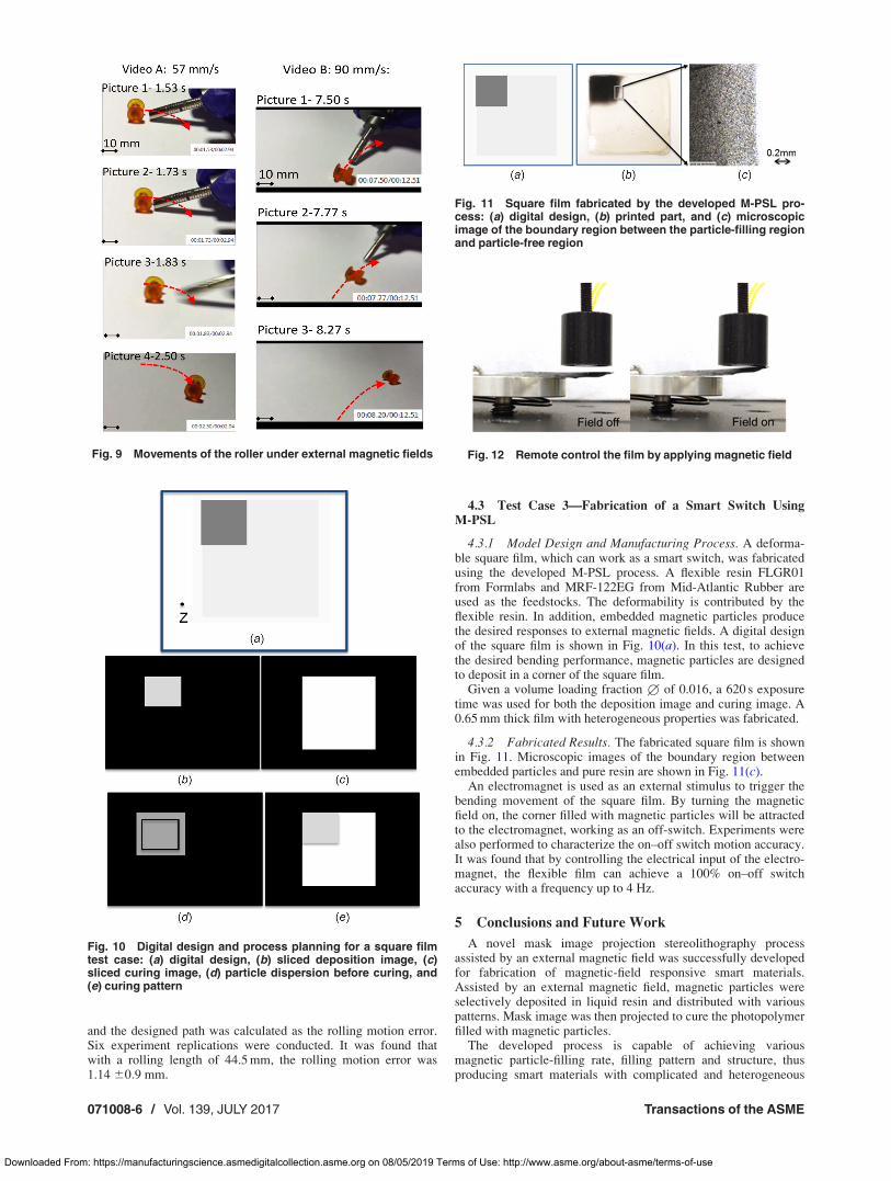
and the designed path was calculated as the rolling motion error.Six experiment replications were conducted. It was found thatwith a rolling length of 44.5 mm, the rolling motion error was1.14 60:9 mm.
4.3 Test Case 3—Fabrication of a Smart Switch UsingM-PSL
4.3.1 Model Design and Manufacturing Process. A deforma-ble square film, which can work as a smart switch, was fabricatedusing the developed M-PSL process. A flexible resin FLGR01from Formlabs and MRF-122EG from Mid-Atlantic Rubber areused as the feedstocks. The deformability is contributed by theflexible resin. In addition, embedded magnetic particles producethe desired responses to external magnetic fields. A digital designof the square film is shown in Fig. 10(a). In this test, to achievethe desired bending performance, magnetic particles are designedto deposit in a corner of the square film.
Given a volume loading fraction 1 of 0.016, a 620 s exposuretime was used for both the deposition image and curing image. A0.65 mm thick film with heterogeneous properties was fabricated.
4.3.2 Fabricated Results. The fabricated square film is shownin Fig. 11. Microscopic images of the boundary region betweenembedded particles and pure resin are shown in Fig. 11(c).
An electromagnet is used as an external stimulus to trigger thebending movement of the square film. By turning the magneticfield on, the corner filled with magnetic particles will be attractedto the electromagnet, working as an off-switch. Experiments werealso performed to characterize the on–off switch motion accuracy.It was found that by controlling the electrical input of the electro-magnet, the flexible film can achieve a 100% on–off switchaccuracy with a frequency up to 4 Hz.
5 Conclusions and Future Work
A novel mask image projection stereolithography processassisted by an external magnetic field was successfully developedfor fabrication of magnetic-field responsive smart materials.Assisted by an external magnetic field, magnetic particles wereselectively deposited in liquid resin and distributed with variouspatterns. Mask image was then projected to cure the photopolymerfilled with magnetic particles.
The developed process is capable of achieving variousmagnetic particle-filling rate, filling pattern and structure, thusproducing smart materials with complicated and heterogeneous
Fig. 9 Movements of the roller under external magnetic fields
Fig. 10 Digital design and process planning for a square filmtest case: (a) digital design, (b) sliced deposition image, (c)sliced curing image, (d) particle dispersion before curing, and(e) curing pattern
Fig. 11 Square film fabricated by the developed M-PSL pro-cess: (a) digital design, (b) printed part, and (c) microscopicimage of the boundary region between the particle-filling regionand particle-free region
Fig. 12 Remote control the film by applying magnetic field
071008-6 / Vol. 139, JULY 2017 Transactions of the ASME
Downloaded From: https://manufacturingscience.asmedigitalcollection.asme.org on 08/05/2019 Terms of Use: http://www.asme.org/about-asme/terms-of-use
functions. As a concept-of-proof, three test cases have been per-formed. The experimental results demonstrate the feasibility andeffectiveness of the proposed magnetic field-assisted projectionstereolithography (M-PSL) technology in production of smartmaterials.
Future work will include: (1) Investigate methods for control-ling the particle deposition more accurately; (2) Characterize therelationship between magnetic particle filling parameters, includ-ing filling rate, patterns, and orientations, on the macroscopic per-formance of the fabricated composite; and (3) Investigate the useof this technology in producing more complicated designs andsmart machines.
References[1] Filipcsei, G., Ildik�o, C., Andr�as, S., and Mikl�os, Z., 2007, “Magnetic
Field-Responsive Smart Polymer Composites,” Oligomers-PolymerComposites-Molecular Imprinting, Springer, Berlin, pp. 137–189.
[2] Pacchioni, G., 2013, “Smart Materials From Nanotechnology for GlobalChallenges,” J. Nanotechnol. Smart Mater., 1, p. 1.
[3] Armentano, I., Dottori, M., Fortunati, E., Mattioli, S., and Kenny, J. M., 2010,“Biodegradable Polymer Matrix Nanocomposites for Tissue Engineering: AReview,” Polym. Degrad. Stab., 95(11), pp. 2126–2146.
[4] Gandhi, M. V., and Thompson, B. D., 1992, Smart Materials and Structures,Springer Science & Business Media/Chapman & Hall, New York/London.
[5] Hoffman, A. S., 2013, “Stimuli-Responsive Polymers: Biomedical Applicationsand Challenges for Clinical Translation,” Adv. Drug Delivery Rev., 65(1),pp. 10–16.
[6] Hu, J., Meng, H., Li, G., and Ibekwe, S. I., 2012, “A Review of Stimuli-Responsive Polymers for Smart Textile Applications,” Smart Mater. Struct.,21(5), p. 053001.
[7] Hussain, F., Hojjati, M., Okamoto, M., and Gorga, R. E., 2006, “ReviewArticle: Polymer-Matrix Nanocomposites, Processing, Manufacturing, andApplication: An Overview,” J. Compos. Mater., 40(17), pp. 1511–1575.
[8] Ionov, L., 2013, “3D Microfabrication Using Stimuli-Responsive Self-FoldingPolymer Films,” Polym. Rev., 53(1), pp. 92–107.
[9] Meng, H., and Li, G., 2013, “A Review of Stimuli-Responsive Shape MemoryPolymer Composites,” Polymer, 54(9), pp. 2199–2221.
[10] Okano, T., ed., 1998, Biorelated Polymers and Gels: Controlled Release andApplications in Biomedical Engineering, Academic Press, Cambridge, MA.
[11] Reece, L., 2007, Smart Materials and Structures: New Research, NovaPublishers, New York.
[12] Kim, K. J., and Shahinpoor, M., 2003, “Ionic Polymer–Metal Composites—II:Manufacturing Techniques,” Smart Mater. Struct., 12(1), p. 65.
[13] Huang, S. H., Liu, P., Mokasdar, A., and Hou, L., 2013, “Additive Manufactur-ing and Its Societal Impact: A Literature Review,” Int. J. Adv. Manuf. Technol.,67(5–8), pp. 1191–1203.
[14] Khalil, S., Nam, J., and Sun, W., 2005, “Multi-Nozzle Deposition for Construc-tion of 3D Biopolymer Tissue Scaffolds,” Rapid Prototyping J., 11(1),pp. 9–17.
[15] Zhou, C., Chen, Y., Yang, Z. G., and Khoshnevis, B., 2011, “Development ofMulti-Material Mask-Image-Projection-Based Stereolithography for theFabrication of Digital Materials,” Solid Freeform Fabrication Symposium(SFF), Austin, TX, Aug. 8–10, pp. 65–80.
[16] Jackson, B., Wood, K., and Beaman, J., 2000, “Discrete Multi-Material Selec-tive Laser Sintering (M 2 SLS): Development for an Application in ComplexSand Casting Core Arrays,” Solid Freeform Fabrication, Austin, TX,pp. 176–182.
[17] Liew, C. L., Leong, K. F., Chua, C. K., and Du, Z., 2001, “Dual Material RapidPrototyping Techniques for the Development of Biomedical Devices—Part 1:Space Creation,” Int. J. Adv. Manuf. Technol., 18(10), pp. 717–723.
[18] Liew, C. L., Leong, K. F., Chua, C. K., and Du, Z., 2002, “Dual Material RapidPrototyping Techniques for the Development of Biomedical Devices—Part 2:Secondary Powder Deposition,” Int. J. Adv. Manuf. Technol., 19(9), pp. 679–687.
[19] Santosa, J., Jing, D., and Das, S., 2002, “Experimental and Numerical Study onthe Flow of Fine Powders From Small-Scale Hoppers Applied to SLS Multi-Material Deposition—Part I,” Solid Freeform Fabrication Symposium (SFF),Austin, TX, Aug. 5–7, pp. 620–627.
[20] Bartolo, P. J., and Gaspar, J., 2008, “Metal Filled Resin for StereolithographyMetal Part,” CIRP Ann.-Manuf. Technol., 57(1), pp. 235–238.
[21] Kumar, S., and Kruth, J. P., 2010, “Composites by Rapid Prototyping Tech-nology,” Mater. Des., 31(2), pp. 850–856.
[22] Wurm, G., Tomancok, B., Holl, K., and Trenkler, J., 2004, “Prospective Studyon Cranioplasty With Individual Carbon Fiber Reinforced Polymere (CFRP)Implants Produced by Means of Stereolithography,” Surg. Neurol., 62(6),pp. 510–521.
[23] Pan, Y., Zhou, C., Chen, Y., and Partanen, J., 2014, “Multitool and Multi-AxisComputer Numerically Controlled Accumulation for Fabricating ConformalFeatures on Curved Surfaces,” ASME J. Manuf. Sci. Eng., 136(3), p. 031007.
[24] B�artolo, P. J., ed., 2011, Stereolithography: Materials, Processes and Applica-tions, Springer Science & Business Media, Berlin.
[25] Pan, Y., and Chen, Y., 2015, “Smooth Surface Fabrication Based on ControlledMeniscus and Cure Depth in Microstereolithography,” J. Micro Nano-Manuf.,3(3), p. 031001.
[26] Pan, Y., Zhao, X., Zhou, C., and Chen, Y., 2012, “Smooth Surface Fabricationin Mask Projection Based Stereolithography,” J. Manuf. Process., 14(4),pp. 460–470.
[27] Pan, Y., Zhou, C., and Chen, Y., 2012, “A Fast Mask Projection Stereolithogra-phy Process for Fabricating Digital Models in Minutes,” ASME J. Manuf. Sci.Eng., 134(5), p. 051011.
[28] Tumbleston, J. R., Shirvanyants, D., Ermoshkin, N., Janusziewicz, R., Johnson,A. R., Kelly, D., Chen, K., Pinschmidt, R., Rolland, J. P., Ermoshkin, A., andSamulski, E. T., 2015, “Continuous Liquid Interface Production of 3D Objects,”Science, 347(6228), pp. 1349–1352.
[29] Mid-Atlantic, Inc., 2015, “MRF-122EG Magneto-Rheological Fluid,” Mid-Atlantic Rubber Co., Baltimore, MD, accessed Dec. 20, 2016, http://www.lordmrstore.com/lord-mr-products/mrf-122eg-magneto-rheological-fluid
Journal of Manufacturing Science and Engineering JULY 2017, Vol. 139 / 071008-7
Downloaded From: https://manufacturingscience.asmedigitalcollection.asme.org on 08/05/2019 Terms of Use: http://www.asme.org/about-asme/terms-of-use