Embed Size (px)
Citation preview
Physics 30 — Unit 2B
Magnetic Forces & Fields
(Revised October 2010)
PHYSICS 30 (Unit 2B) 1
Electromagnetism
• A flow of electric charge is called an electric current. Current
(I) is defined mathematically as
t
QI
∆
∆= .
• The SI unit of current is the Ampere (A = C/s).
• Hans Christian Oersted discovered that electric currents
deflected the needle of a magnetic compass. This phenomenon
is called electromagnetism.
• Magnetism refers to a force that acts between electric charges
only when the charges are in motion. This “magnetic force” is
in addition to the electric force that acts between charges even
when they are not moving.
• Some materials have magnetic properties. Materials that can be
permanently magnetized are called ferromagnetic. Iron and
nickel are two of the most common ferromagnetic materials. By
contrast, paramagnetic materials become magnetized when
another magnet is nearby, but return to being unmagnetized
when the nearby magnet is removed.
• As with gravitational and electric forces, physicists use the
concept of a field to understand how magnetic forces work.
Moving charges (i.e. electric currents) produce a magnetic field.
The magnetic field then exerts a magnetic force on other nearby
moving charges.
• The symbol for magnetic field is B�
and the SI unit is the Tesla
(T).
• Ampere’s Law states that the strength of a magnetic field is
directly proportional to the current that produces it; i.e. doubling
the current flowing through a wire will double the magnetic
field strength.
• A diagram of a magnetic field illustrates the direction that a
compass needle will point when placed at each position within
the field.
• As with electric and gravitational field diagrams, the strength of
the field corresponds to the density of field lines.
• A unique property of magnetic fields is that there are no points
of convergence or divergence: magnetic field lines always form
closed loops with no beginning or end!
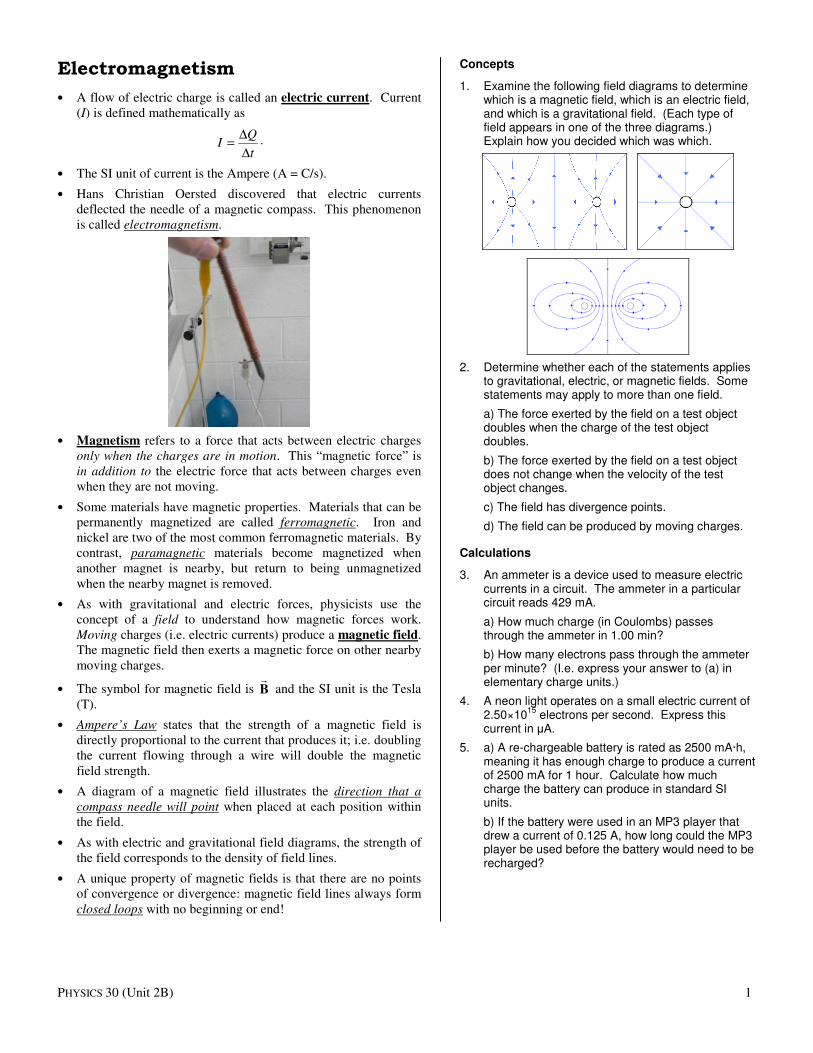
Concepts
1. Examine the following field diagrams to determine which is a magnetic field, which is an electric field, and which is a gravitational field. (Each type of field appears in one of the three diagrams.) Explain how you decided which was which.
2. Determine whether each of the statements applies to gravitational, electric, or magnetic fields. Some statements may apply to more than one field.
a) The force exerted by the field on a test object doubles when the charge of the test object doubles.
b) The force exerted by the field on a test object does not change when the velocity of the test object changes.
c) The field has divergence points.
d) The field can be produced by moving charges.
Calculations
3. An ammeter is a device used to measure electric currents in a circuit. The ammeter in a particular circuit reads 429 mA.
a) How much charge (in Coulombs) passes through the ammeter in 1.00 min?
b) How many electrons pass through the ammeter per minute? (I.e. express your answer to (a) in elementary charge units.)
4. A neon light operates on a small electric current of 2.50×10
15 electrons per second. Express this
current in µA.
5. a) A re-chargeable battery is rated as 2500 mA·h, meaning it has enough charge to produce a current of 2500 mA for 1 hour. Calculate how much charge the battery can produce in standard SI units.
b) If the battery were used in an MP3 player that drew a current of 0.125 A, how long could the MP3 player be used before the battery would need to be recharged?
PHYSICS 30 (Unit 2B) 2
Lab Activity: Measuring Magnetic Fields
While a compass needle is a simple and convenient way to detect a magnetic field and observe its direction, it has some limitations. Most compasses are designed to be held horizontally, and therefore cannot be used to tell if the magnetic field has a vertical component. Compasses don’t provide a simple way to quantitatively measure the strength of a magnetic field. Also, the compass needle’s magnetization may change over time (especially if the compass is exposed to strong magnetic fields) causing the compass to function improperly. In this activity, we will observe and measure magnetic fields using an electronic magnetic field sensor, which detects the field by how it affects the motion of electrons flowing through the sensor’s circuitry.
Calibration
1. Plug the magnetic field sensor into Channel 1 of a CBL. Turn the CBL on and press the [Mode] button. The word “Sampling” should begin flashing on the display. Press the [ChView] button until the units are displayed in Volts.
2. Move the sensor far away from any magnets or electrical currents. Set the switch on the sensor to the weak (0.3 mT) setting. Point the white dot at the tip of the sensor straight up. Observe the voltage on the CBL display. Now point the white dot straight down and observe the voltage again. Record the average of these two voltages as the calibration voltage for the weak field setting.
3. Repeat the previous step with the switch on the Strong (6.4 mT) setting. Record the calibration voltage for this setting.
Weak (0.3 mT)
Strong (6.4 mT)
Calibration Vc / Volts
Sensitivity s / (mT/V)
0.160 3.225
Activity 1: Earth’s Magnetic Field
1. a) Move the probe far away from any magnets and electric currents so that you can measure the Earth’s magnetic field. Set the amplifier switch to weak (0.3 mT). Hold the wand so that the sensor’s white dot is pointing horizontally. Rotate the sensor wand, keeping the white dot pointing in a horizontal direction, until you register a maximum voltage. Record this voltage.
b) The direction that the white dot is pointing when the output voltage is a maximum indicates the direction of the horizontal component of Earth’s magnetic field (Bx). Is the observed direction of Bx as expected? Explain.
c) Use the calibration data to convert your recorded voltage to a magnetic field strength with the formula Bx = s (V – Vc). The symbols Vc and s are the calibration voltage and the sensitivity of the field sensor.
d) Point the sensor’s white dot straight up, and then straight down. Which orientation gives a higher voltage reading? This is the direction of the vertical component of Earth’s magnetic field. Record the displayed voltage and calculate the vertical magnetic field using the same equation as above.
e) Convert the magnetic field vector to polar form.
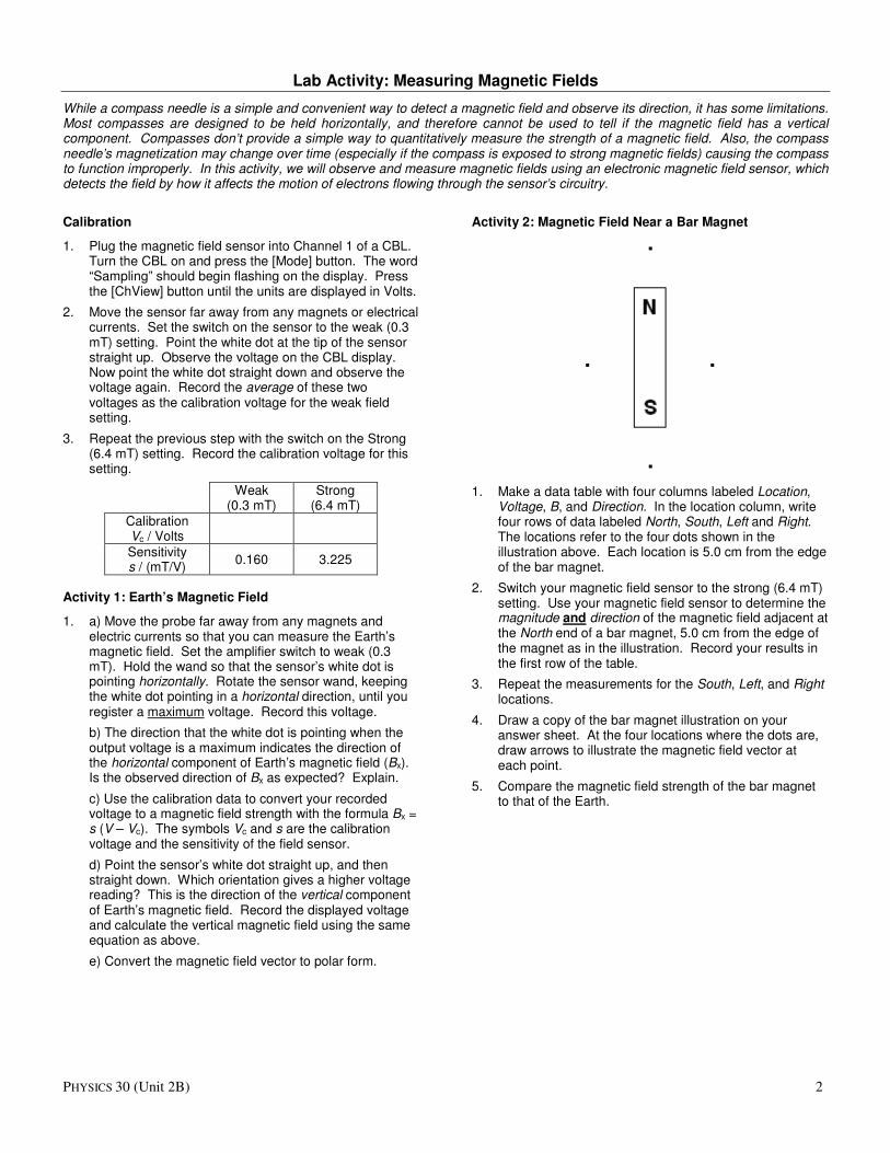
Activity 2: Magnetic Field Near a Bar Magnet
1. Make a data table with four columns labeled Location, Voltage, B, and Direction. In the location column, write four rows of data labeled North, South, Left and Right. The locations refer to the four dots shown in the illustration above. Each location is 5.0 cm from the edge of the bar magnet.
2. Switch your magnetic field sensor to the strong (6.4 mT) setting. Use your magnetic field sensor to determine the magnitude and direction of the magnetic field adjacent at the North end of a bar magnet, 5.0 cm from the edge of the magnet as in the illustration. Record your results in the first row of the table.
3. Repeat the measurements for the South, Left, and Right locations.
4. Draw a copy of the bar magnet illustration on your answer sheet. At the four locations where the dots are, draw arrows to illustrate the magnetic field vector at each point.
5. Compare the magnetic field strength of the bar magnet to that of the Earth.
Name:
Lab Activity: Measuring Magnetic Fields
While a compass needle is a simple and convenient way to detect a magnetic field and observe its direction, it has some limitations. Most compasses are designed to be held horizontally, and therefore cannot be used to tell if the magnetic field has a vertical component. Compasses don’t provide a simple way to quantitatively measure the strength of a magnetic field. Also, the compass needle’s magnetization may change over time (especially if the compass is exposed to strong magnetic fields) causing the compass to function improperly. In this activity, we will observe and measure magnetic fields using an electronic magnetic field sensor, which detects the field by how it affects the motion of electrons flowing through the sensor’s circuitry.
Activity 1: Earth’s Magnetic Field
1. Set the amplifier switch on the magnetic field sensor to the “Weak” (0.3 mT) setting. Connect the sensor to a CBL (Ch1). Load the Vernier Physics program onto your TI-83+ calculator and connect the CBL to the calculator. Run the program and set it up for one magnetic field sensor. Do a manual calibration and set the intercept to 0 and the slope to 1.
2. Set the program to Collect Data. Use the Monitor Input mode. Hold the sensor so that the white dot points in a horizontal direction. Slowly rotate the sensor through 360° with the white dot always horizontal. Make a note of the direction of the dot when the output of the sensor reaches its maximum value. Describe this direction.
3. Record the output voltages of the sensor with the white dot pointing toward the exact front and the exact back of the room. Calculate the “y” component of the Earth’s magnetic field by multiplying the difference between these voltages by 80 µT/V (the sensitivity of the probe using the “Weak” amplifier setting).
“Front” Voltage / V
“Back” Voltage / V By / µT
4. Record the output voltages of the sensor with the white dot pointing toward the exact right side and the exact left of the room. Calculate the “x” component of the Earth’s magnetic field by multiplying the difference between these voltages by 80 µT/V.
“Right” Voltage / V
“Left” Voltage / V
Bx / µT
5. Calculate the Earth’s horizontal magnetic field by applying the Pythagoras formula to the x and y components.
6. Does Earth’s magnetic field have a vertical component? Measure the magnetic field sensor output for the exact “up” and “down” directions. Use the same method as above to calculate the vertical (“z”) field component.
“Up” Voltage / V
“Down” Voltage / V
Bz / µT
7. Draw a vector diagram of Earth’s horizontal (#5) and vertical (#6) magnetic field components on graph paper. Calculate the magnitude and direction of the magnetic field vector. Show your calculations on the back of your graph paper.
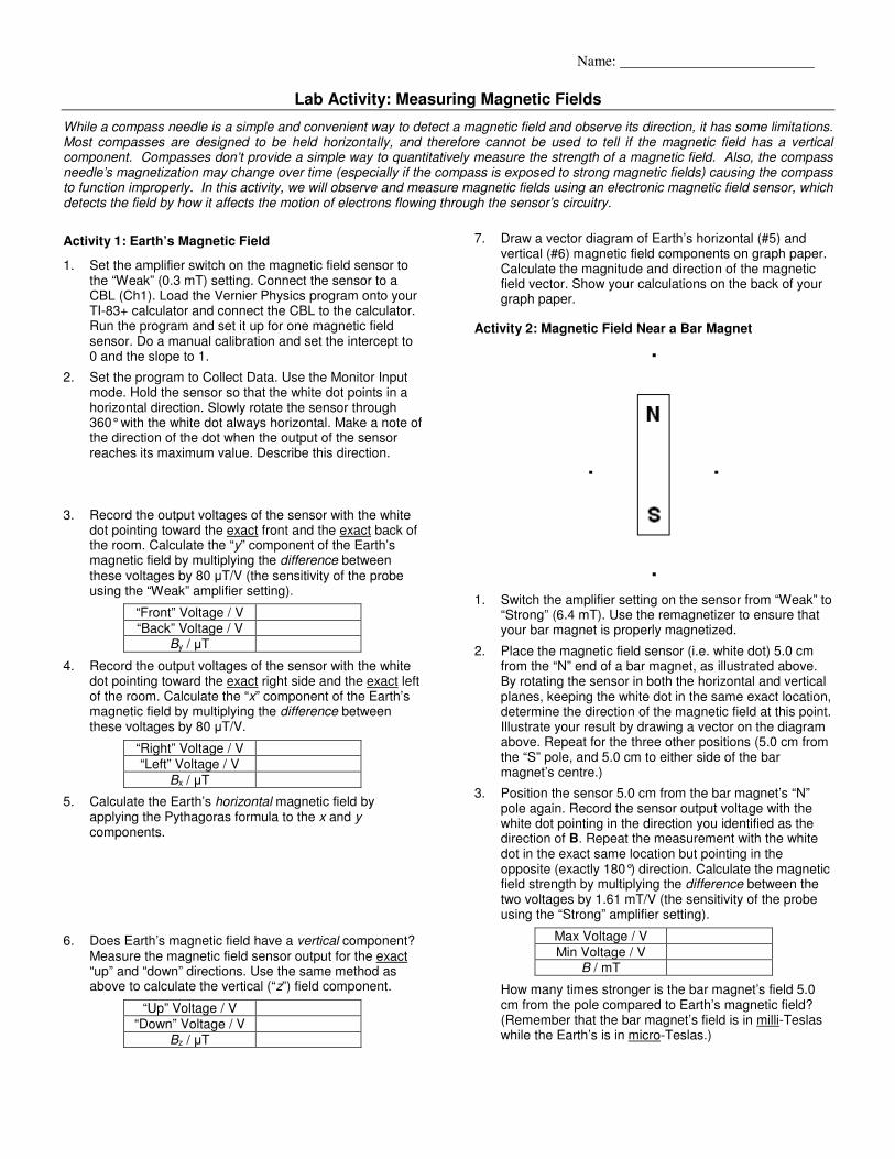
Activity 2: Magnetic Field Near a Bar Magnet
1. Switch the amplifier setting on the sensor from “Weak” to “Strong” (6.4 mT). Use the remagnetizer to ensure that your bar magnet is properly magnetized.
2. Place the magnetic field sensor (i.e. white dot) 5.0 cm from the “N” end of a bar magnet, as illustrated above. By rotating the sensor in both the horizontal and vertical planes, keeping the white dot in the same exact location, determine the direction of the magnetic field at this point. Illustrate your result by drawing a vector on the diagram above. Repeat for the three other positions (5.0 cm from the “S” pole, and 5.0 cm to either side of the bar magnet’s centre.)
3. Position the sensor 5.0 cm from the bar magnet’s “N” pole again. Record the sensor output voltage with the white dot pointing in the direction you identified as the direction of B. Repeat the measurement with the white dot in the exact same location but pointing in the opposite (exactly 180°) direction. Calculate the magnetic field strength by multiplying the difference between the two voltages by 1.61 mT/V (the sensitivity of the probe using the “Strong” amplifier setting).
Max Voltage / V
Min Voltage / V B / mT
How many times stronger is the bar magnet’s field 5.0 cm from the pole compared to Earth’s magnetic field? (Remember that the bar magnet’s field is in milli-Teslas while the Earth’s is in micro-Teslas.)
PHYSICS 30 (Unit 2B) 3
1st & 2
nd Hand Rules
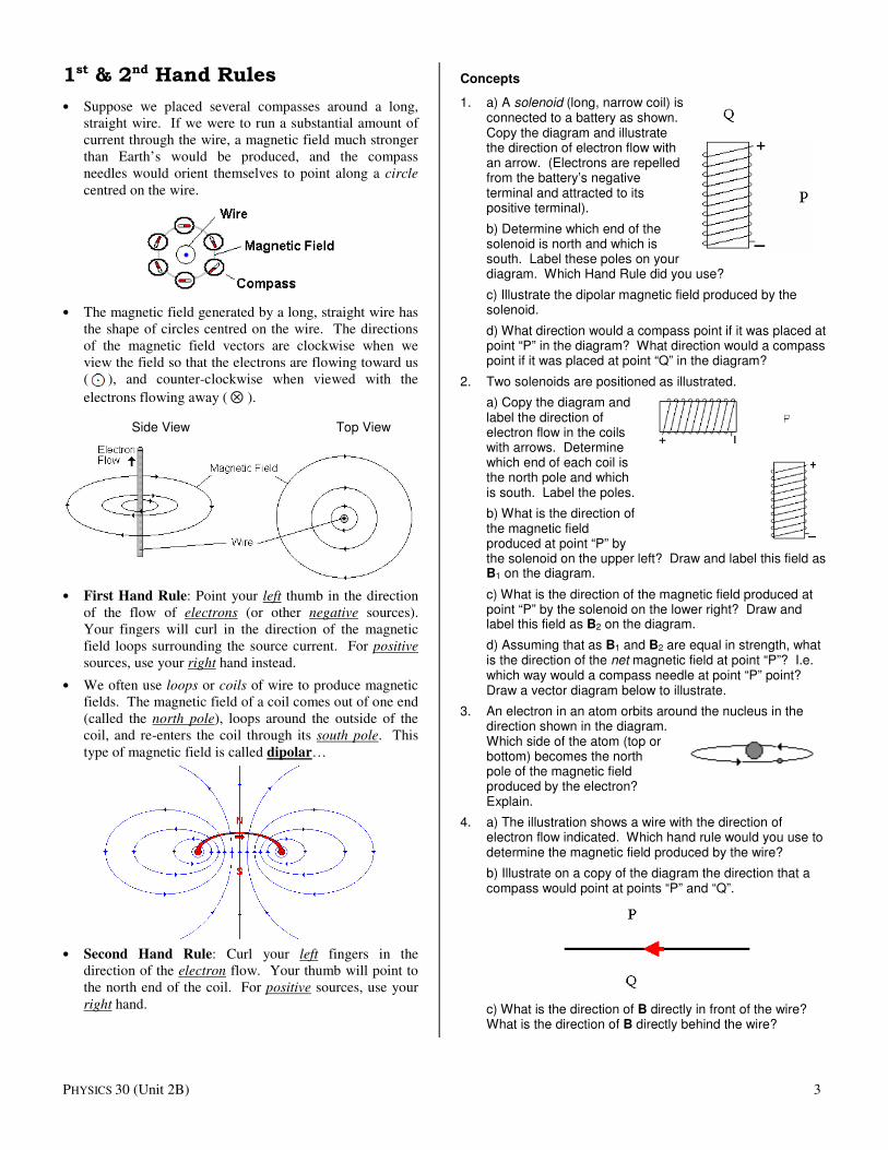
• Suppose we placed several compasses around a long,
straight wire. If we were to run a substantial amount of
current through the wire, a magnetic field much stronger
than Earth’s would be produced, and the compass
needles would orient themselves to point along a circle
centred on the wire.
• The magnetic field generated by a long, straight wire has
the shape of circles centred on the wire. The directions
of the magnetic field vectors are clockwise when we
view the field so that the electrons are flowing toward us
( ), and counter-clockwise when viewed with the
electrons flowing away ( ⊗ ).
Side View Top View
• First Hand Rule: Point your left thumb in the direction
of the flow of electrons (or other negative sources).
Your fingers will curl in the direction of the magnetic
field loops surrounding the source current. For positive
sources, use your right hand instead.
• We often use loops or coils of wire to produce magnetic
fields. The magnetic field of a coil comes out of one end
(called the north pole), loops around the outside of the
coil, and re-enters the coil through its south pole. This
type of magnetic field is called dipolar…
• Second Hand Rule: Curl your left fingers in the
direction of the electron flow. Your thumb will point to
the north end of the coil. For positive sources, use your
right hand.
Concepts
1. a) A solenoid (long, narrow coil) is connected to a battery as shown. Copy the diagram and illustrate the direction of electron flow with an arrow. (Electrons are repelled from the battery’s negative terminal and attracted to its positive terminal).
b) Determine which end of the solenoid is north and which is south. Label these poles on your diagram. Which Hand Rule did you use?
c) Illustrate the dipolar magnetic field produced by the solenoid.
d) What direction would a compass point if it was placed at point “P” in the diagram? What direction would a compass point if it was placed at point “Q” in the diagram?
2. Two solenoids are positioned as illustrated.
a) Copy the diagram and label the direction of electron flow in the coils with arrows. Determine which end of each coil is the north pole and which is south. Label the poles.
b) What is the direction of the magnetic field produced at point “P” by the solenoid on the upper left? Draw and label this field as B1 on the diagram.
c) What is the direction of the magnetic field produced at point “P” by the solenoid on the lower right? Draw and label this field as B2 on the diagram.
d) Assuming that as B1 and B2 are equal in strength, what is the direction of the net magnetic field at point “P”? I.e. which way would a compass needle at point “P” point? Draw a vector diagram below to illustrate.
3. An electron in an atom orbits around the nucleus in the direction shown in the diagram. Which side of the atom (top or bottom) becomes the north pole of the magnetic field produced by the electron? Explain.
4. a) The illustration shows a wire with the direction of electron flow indicated. Which hand rule would you use to determine the magnetic field produced by the wire?
b) Illustrate on a copy of the diagram the direction that a compass would point at points “P” and “Q”.
c) What is the direction of B directly in front of the wire? What is the direction of B directly behind the wire?
PHYSICS 30 (Unit 2B) 4
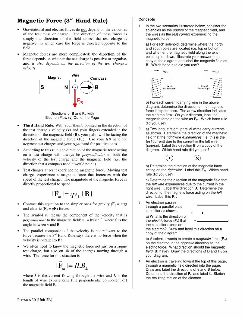
Magnetic Force (3rd Hand Rule)
• Gravitational and electric forces do not depend on the velocities
of the test mass or charge. The direction of these forces is
simply the direction of the field unless the test charge is
negative, in which case the force is directed opposite to the
field.
• Magnetic forces are more complicated: the direction of the
force depends on whether the test charge is positive or negative,
and it also depends on the direction of the test charge’s
velocity.
Directions of B and Fm with Electron Flow (v) Out of the Page
• Third Hand Rule: With your thumb pointed in the direction of
the test charge’s velocity (v) and your fingers extended in the
direction of the magnetic field (B), your palm will be facing the
direction of the magnetic force (Fm). Use your left hand for
negative test charges and your right hand for positive ones.
• According to this rule, the direction of the magnetic force acting
on a test charge will always be perpendicular to both the
velocity of the test charge and the magnetic field (i.e. the
direction that a compass needle would point.)
• Test charges at rest experience no magnetic force. Moving test
charges experience a magnetic force that increases with the
speed of the test charge. The magnitude of the magnetic force is
directly proportional to speed:
| | | |m qv⊥
=F B� �
• Contrast this equation to the simpler ones for gravity (Fg = mg)
and electric (Fe = qE) forces.
• The symbol v⊥ means the component of the velocity that is
perpendicular to the magnetic field: v⊥ = |v| sin θ, where θ is the
angle between v and B.
• The parallel component of the velocity is not relevant to the
force because the 3rd
Hand Rule says there is no force when the
velocity is parallel to B!
• We often need to know the magnetic force not just on a single
test charge, but also on all of the charges moving through a
wire. The force for this situation is
| |m ILB⊥
=F�
where I is the current flowing through the wire and L is the
length of wire experiencing (the perpendicular component of)
the magnetic field B.
Concepts
1. In the two scenarios illustrated below, consider the solenoids as the source of the magnetic field, and the wires as the test current experiencing the magnetic force.
a) For each solenoid, determine where the north and south poles are located (i.e. top or bottom), and whether the magnetic field along the axis points up or down. Illustrate your answer on a copy of the diagram and label the magnetic field as B. Which hand rule did you use?
b) For each current-carrying wire in the above diagram, determine the direction of the magnetic force it experiences. The arrow direction indicates the electron flow. On your diagram, label the magnetic force on the wire as Fm. Which hand rule did you use?
2. a) Two long, straight, parallel wires carry currents as shown. Determine the direction of the magnetic field that the right wire experiences (i.e. this is the test current) due to the current in the left wire (source). Label this direction B on a copy of the diagram. Which hand rule did you use?
b) Determine the direction of the magnetic force acting on the right wire. Label this Fm. Which hand rule did you use?
c) Determine the direction of the magnetic field that the left wire experiences due to the current in the right wire. Label this direction B. Determine the direction of the magnetic force acting on the left wire. Label this Fm.
3. An electron passes through a parallel plate capacitor as shown.
a) What is the direction of the electric force (Fe) that the capacitor exerts on the electron? Draw and label this direction on a copy of the diagram.
b) A scientist wants to create a magnetic force (Fm) on the electron in the opposite direction as the electric force. What direction should the magnetic field (B) have? Draw the directions of B and Fm on your diagram.
4. An electron is traveling toward the top of this page, through a magnetic field directed into the page. Draw and label the directions of v and B below. Determine the direction of Fm and label it. Sketch the resulting motion of the electron.
PHYSICS 30 (Unit 2B) 5
Calculations
5. A wire carrying 1.25 A of current experiences a force of 3.25 mN when held perpendicular to the magnetic field between the poles of a horseshoe magnet. If the length of wire within the magnetic field is 5.20 cm, what is the average magnetic field strength? Include a diagram with the directions of v, B and Fm labelled.
6. A wire with 720 mA of current (electron flow = east) passes through a magnetic field of 50.0 mT (down). A total length of 35.0 cm of wire is exposed to the magnetic field. Determine the total magnetic force (including direction) that the wire experiences. Include a diagram with the directions of v, B and Fm labelled.
Problems
7. An alpha particle (see formula sheet) moving with a speed of 9.20×10
4 m/s passes through a uniform
2.05 mT magnetic field and experiences a force of 3.50×10
–17 N. What angle does the particle’s velocity
make with the magnetic field?
8. � A wire experiences an upward magnetic force of 48.2 mN when held so that its current flows north. When the wire is turned so that its current flows east, the magnetic force is 60.5 mN downward. In what direction does the uniform, horizontal magnetic field point?
Lab Activity: Magnetic Forces & Fields
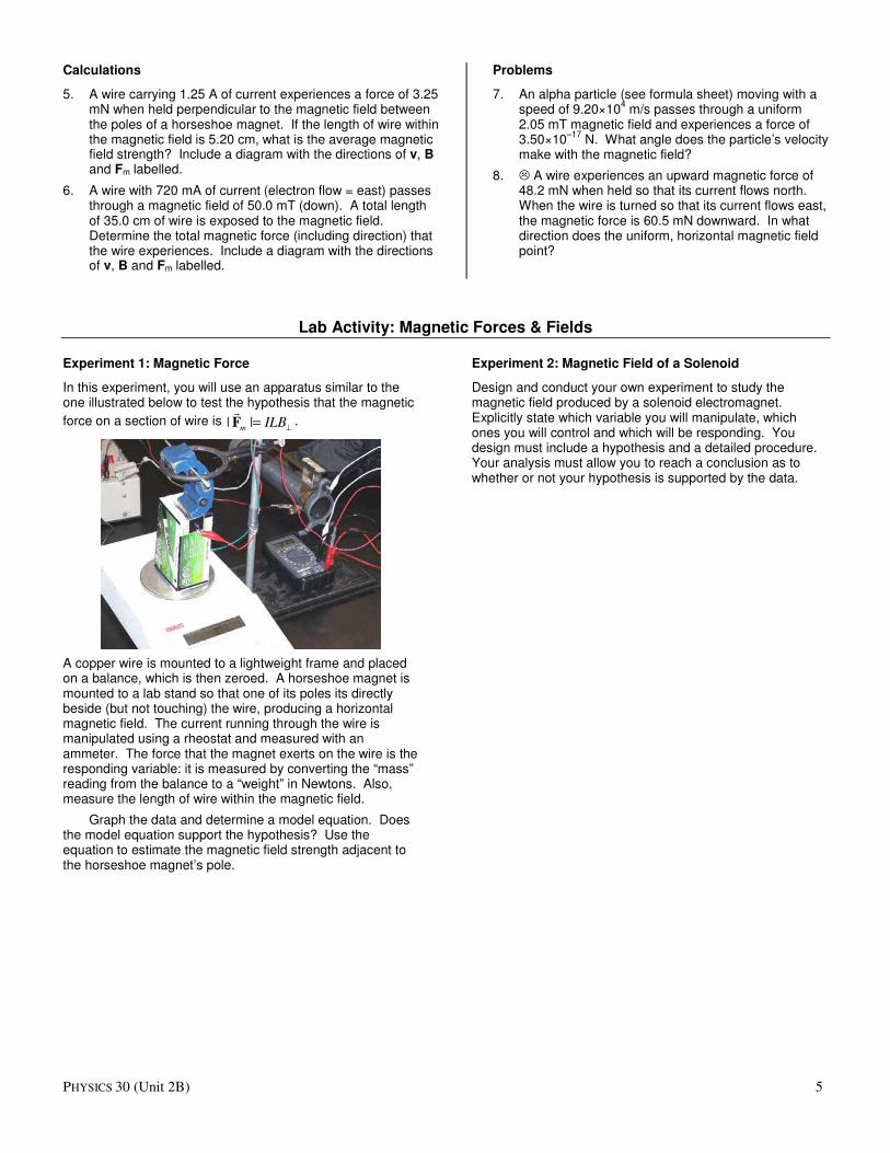
Experiment 1: Magnetic Force
In this experiment, you will use an apparatus similar to the one illustrated below to test the hypothesis that the magnetic
force on a section of wire is | |m ILB⊥
=F�
.
A copper wire is mounted to a lightweight frame and placed on a balance, which is then zeroed. A horseshoe magnet is mounted to a lab stand so that one of its poles its directly beside (but not touching) the wire, producing a horizontal magnetic field. The current running through the wire is manipulated using a rheostat and measured with an ammeter. The force that the magnet exerts on the wire is the responding variable: it is measured by converting the “mass” reading from the balance to a “weight” in Newtons. Also, measure the length of wire within the magnetic field.
Graph the data and determine a model equation. Does the model equation support the hypothesis? Use the equation to estimate the magnetic field strength adjacent to the horseshoe magnet’s pole.
Experiment 2: Magnetic Field of a Solenoid
Design and conduct your own experiment to study the magnetic field produced by a solenoid electromagnet. Explicitly state which variable you will manipulate, which ones you will control and which will be responding. You design must include a hypothesis and a detailed procedure. Your analysis must allow you to reach a conclusion as to whether or not your hypothesis is supported by the data.
PHYSICS 30 (Unit 2B) 6
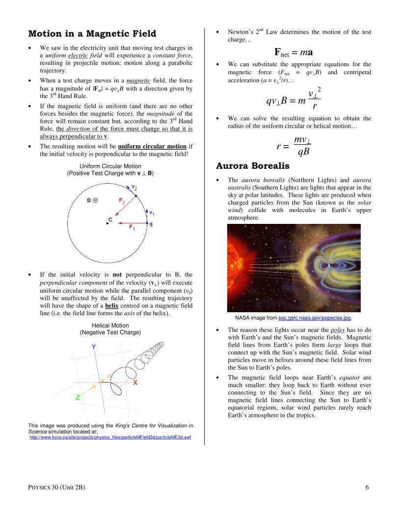
Motion in a Magnetic Field
• We saw in the electricity unit that moving test charges in
a uniform electric field will experience a constant force,
resulting in projectile motion: motion along a parabolic
trajectory.
• When a test charge moves in a magnetic field, the force
has a magnitude of |Fm| = qv⊥B with a direction given by
the 3rd
Hand Rule.
• If the magnetic field is uniform (and there are no other
forces besides the magnetic force), the magnitude of the
force will remain constant but, according to the 3rd
Hand
Rule, the direction of the force must change so that it is
always perpendicular to v.
• The resulting motion will be uniform circular motion if
the initial velocity is perpendicular to the magnetic field!
Uniform Circular Motion (Positive Test Charge with v ⊥ B)
• If the initial velocity is not perpendicular to B, the
perpendicular component of the velocity (v⊥) will execute
uniform circular motion while the parallel component (v||)
will be unaffected by the field. The resulting trajectory
will have the shape of a helix centred on a magnetic field
line (i.e. the field line forms the axis of the helix).
Helical Motion (Negative Test Charge)
This image was produced using the King’s Centre for Visualization in Science simulation located at: http://www.kcvs.ca/site/projects/physics_files/particleMField3d/particleME3d.swf
• Newton’s 2nd
Law determines the motion of the test
charge…
Fnet = ma • We can substitute the appropriate equations for the
magnetic force (Fnet = qv⊥B) and centripetal
acceleration (a = v⊥
2/r)…
qv⊥B = m v⊥
2
r
• We can solve the resulting equation to obtain the
radius of the uniform circular or helical motion…
r = mv⊥
qB
Aurora Borealis
• The aurora borealis (Northern Lights) and aurora
australis (Southern Lights) are lights that appear in the
sky at polar latitudes. These lights are produced when
charged particles from the Sun (known as the solar
wind) collide with molecules in Earth’s upper
atmosphere.
NASA image from sec.gsfc.nasa.gov/popscise.jpg.
• The reason these lights occur near the poles has to do
with Earth’s and the Sun’s magnetic fields. Magnetic
field lines from Earth’s poles form large loops that
connect up with the Sun’s magnetic field. Solar wind
particles move in helixes around these field lines from
the Sun to Earth’s poles.
• The magnetic field loops near Earth’s equator are
much smaller: they loop back to Earth without ever
connecting to the Sun’s field. Since they are no
magnetic field lines connecting the Sun to Earth’s
equatorial regions, solar wind particles rarely reach
Earth’s atmosphere in the tropics.
PHYSICS 30 (Unit 2B) 7
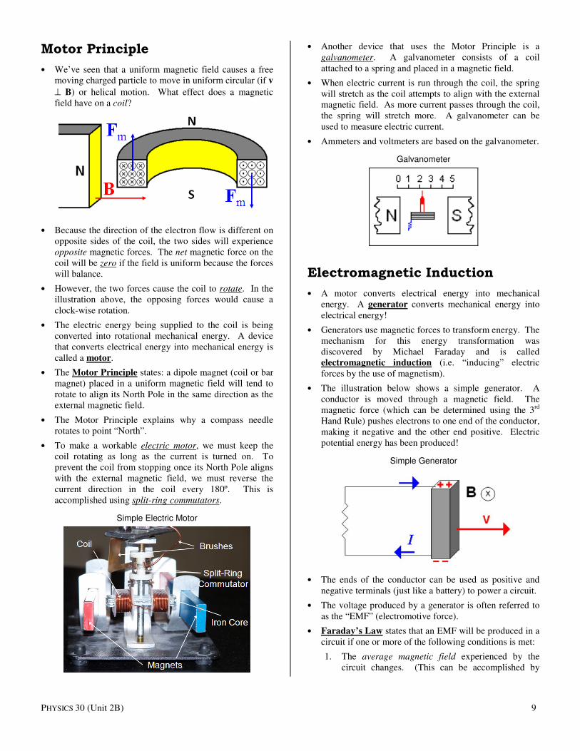
Cyclotron
• A particle accelerator is a device used to accelerate
subatomic particles (e.g. protons) to extremely high
speeds.
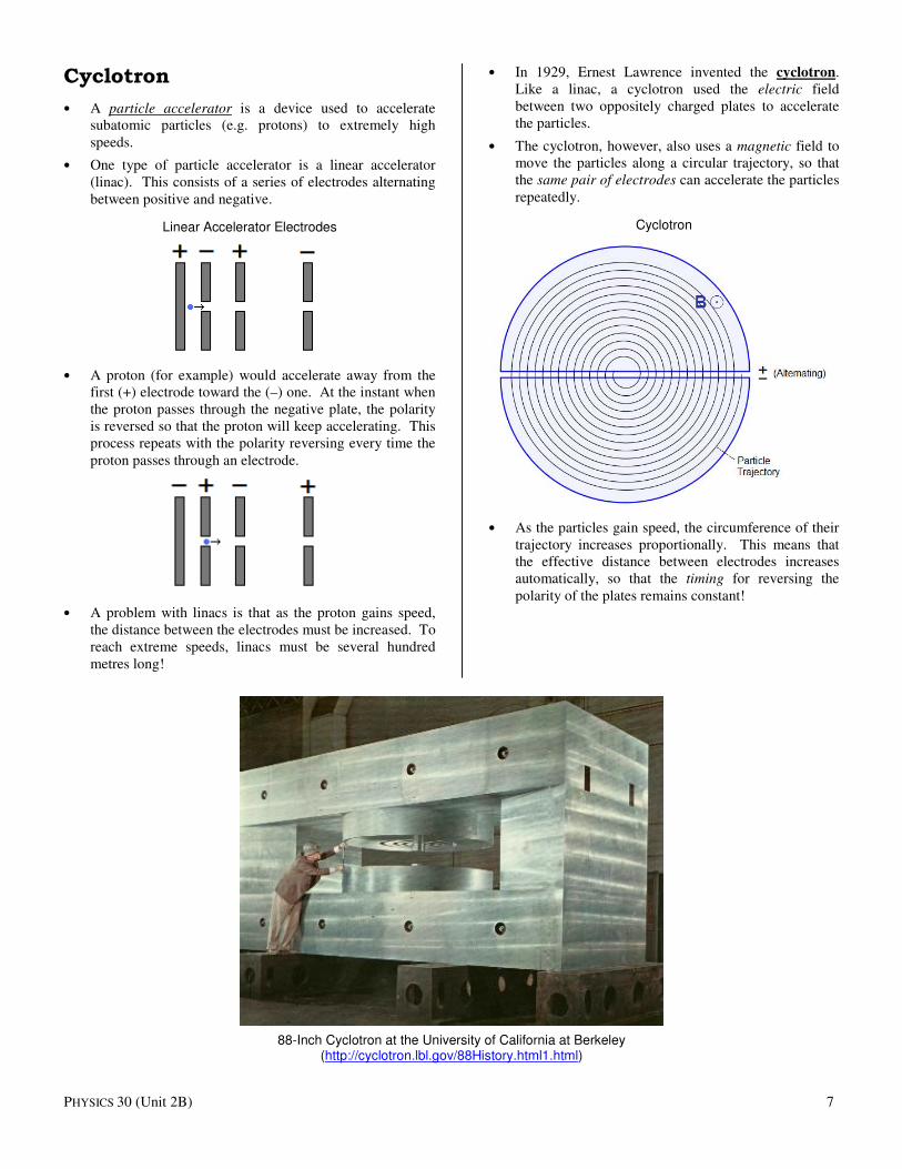
• One type of particle accelerator is a linear accelerator
(linac). This consists of a series of electrodes alternating
between positive and negative.
Linear Accelerator Electrodes
• A proton (for example) would accelerate away from the
first (+) electrode toward the (–) one. At the instant when
the proton passes through the negative plate, the polarity
is reversed so that the proton will keep accelerating. This
process repeats with the polarity reversing every time the
proton passes through an electrode.
• A problem with linacs is that as the proton gains speed,
the distance between the electrodes must be increased. To
reach extreme speeds, linacs must be several hundred
metres long!
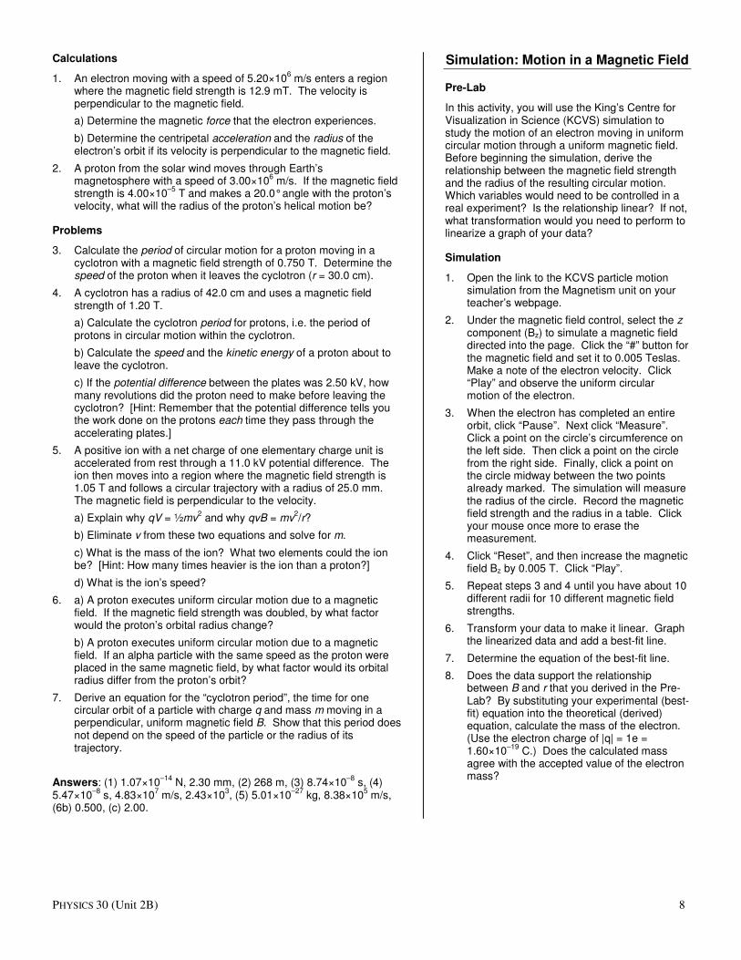
• In 1929, Ernest Lawrence invented the cyclotron.
Like a linac, a cyclotron used the electric field
between two oppositely charged plates to accelerate
the particles.
• The cyclotron, however, also uses a magnetic field to
move the particles along a circular trajectory, so that
the same pair of electrodes can accelerate the particles
repeatedly.
Cyclotron
• As the particles gain speed, the circumference of their
trajectory increases proportionally. This means that
the effective distance between electrodes increases
automatically, so that the timing for reversing the
polarity of the plates remains constant!
88-Inch Cyclotron at the University of California at Berkeley (http://cyclotron.lbl.gov/88History.html1.html)
PHYSICS 30 (Unit 2B) 8
Calculations
1. An electron moving with a speed of 5.20×10⁶ m/s enters a region
where the magnetic field strength is 12.9 mT. The velocity is perpendicular to the magnetic field.
a) Determine the magnetic force that the electron experiences.
b) Determine the centripetal acceleration and the radius of the electron’s orbit if its velocity is perpendicular to the magnetic field.
2. A proton from the solar wind moves through Earth’s magnetosphere with a speed of 3.00×10
6 m/s. If the magnetic field
strength is 4.00×10⁻⁵
T and makes a 20.0° angle with the proton’s velocity, what will the radius of the proton’s helical motion be?
Problems
3. Calculate the period of circular motion for a proton moving in a cyclotron with a magnetic field strength of 0.750 T. Determine the speed of the proton when it leaves the cyclotron (r = 30.0 cm).
4. A cyclotron has a radius of 42.0 cm and uses a magnetic field strength of 1.20 T.
a) Calculate the cyclotron period for protons, i.e. the period of protons in circular motion within the cyclotron.
b) Calculate the speed and the kinetic energy of a proton about to leave the cyclotron.
c) If the potential difference between the plates was 2.50 kV, how many revolutions did the proton need to make before leaving the cyclotron? [Hint: Remember that the potential difference tells you the work done on the protons each time they pass through the accelerating plates.]
5. A positive ion with a net charge of one elementary charge unit is accelerated from rest through a 11.0 kV potential difference. The ion then moves into a region where the magnetic field strength is 1.05 T and follows a circular trajectory with a radius of 25.0 mm. The magnetic field is perpendicular to the velocity.
a) Explain why qV = ½mv2 and why qvB = mv
2/r?
b) Eliminate v from these two equations and solve for m.
c) What is the mass of the ion? What two elements could the ion be? [Hint: How many times heavier is the ion than a proton?]
d) What is the ion’s speed?
6. a) A proton executes uniform circular motion due to a magnetic field. If the magnetic field strength was doubled, by what factor would the proton’s orbital radius change?
b) A proton executes uniform circular motion due to a magnetic field. If an alpha particle with the same speed as the proton were placed in the same magnetic field, by what factor would its orbital radius differ from the proton’s orbit?
7. Derive an equation for the “cyclotron period”, the time for one circular orbit of a particle with charge q and mass m moving in a perpendicular, uniform magnetic field B. Show that this period does not depend on the speed of the particle or the radius of its trajectory.
Answers: (1) 1.07×10⁻¹⁴
N, 2.30 mm, (2) 268 m, (3) 8.74×10⁻⁸
s, (4) 5.47×10
–8 s, 4.83×10
7 m/s, 2.43×10
3, (5) 5.01×10
–27 kg, 8.38×10
5 m/s,
(6b) 0.500, (c) 2.00.
Simulation: Motion in a Magnetic Field
Pre-Lab
In this activity, you will use the King’s Centre for Visualization in Science (KCVS) simulation to study the motion of an electron moving in uniform circular motion through a uniform magnetic field. Before beginning the simulation, derive the relationship between the magnetic field strength and the radius of the resulting circular motion. Which variables would need to be controlled in a real experiment? Is the relationship linear? If not, what transformation would you need to perform to linearize a graph of your data?
Simulation
1. Open the link to the KCVS particle motion simulation from the Magnetism unit on your teacher’s webpage.
2. Under the magnetic field control, select the z component (Bz) to simulate a magnetic field directed into the page. Click the “#” button for the magnetic field and set it to 0.005 Teslas. Make a note of the electron velocity. Click “Play” and observe the uniform circular motion of the electron.
3. When the electron has completed an entire orbit, click “Pause”. Next click “Measure”. Click a point on the circle’s circumference on the left side. Then click a point on the circle from the right side. Finally, click a point on the circle midway between the two points already marked. The simulation will measure the radius of the circle. Record the magnetic field strength and the radius in a table. Click your mouse once more to erase the measurement.
4. Click “Reset”, and then increase the magnetic field Bz by 0.005 T. Click “Play”.
5. Repeat steps 3 and 4 until you have about 10 different radii for 10 different magnetic field strengths.
6. Transform your data to make it linear. Graph the linearized data and add a best-fit line.
7. Determine the equation of the best-fit line.
8. Does the data support the relationship between B and r that you derived in the Pre-Lab? By substituting your experimental (best-fit) equation into the theoretical (derived) equation, calculate the mass of the electron. (Use the electron charge of |q| = 1e = 1.60×10
–19 C.) Does the calculated mass
agree with the accepted value of the electron mass?
PHYSICS 30 (Unit 2B) 9
Motor Principle
• We’ve seen that a uniform magnetic field causes a free
moving charged particle to move in uniform circular (if v
⊥ B) or helical motion. What effect does a magnetic
field have on a coil?
• Because the direction of the electron flow is different on
opposite sides of the coil, the two sides will experience
opposite magnetic forces. The net magnetic force on the
coil will be zero if the field is uniform because the forces
will balance.
• However, the two forces cause the coil to rotate. In the
illustration above, the opposing forces would cause a
clock-wise rotation.
• The electric energy being supplied to the coil is being
converted into rotational mechanical energy. A device
that converts electrical energy into mechanical energy is
called a motor.
• The Motor Principle states: a dipole magnet (coil or bar
magnet) placed in a uniform magnetic field will tend to
rotate to align its North Pole in the same direction as the
external magnetic field.
• The Motor Principle explains why a compass needle
rotates to point “North”.
• To make a workable electric motor, we must keep the
coil rotating as long as the current is turned on. To
prevent the coil from stopping once its North Pole aligns
with the external magnetic field, we must reverse the
current direction in the coil every 180º. This is
accomplished using split-ring commutators.
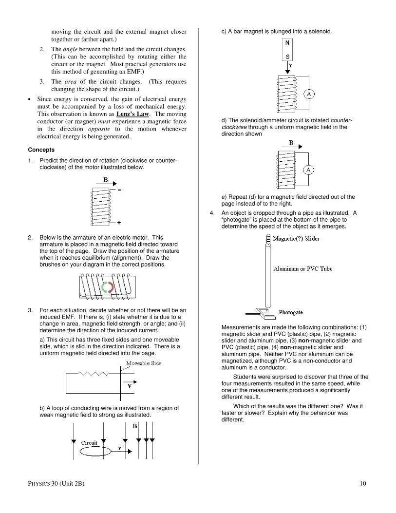
Simple Electric Motor
• Another device that uses the Motor Principle is a
galvanometer. A galvanometer consists of a coil
attached to a spring and placed in a magnetic field.
• When electric current is run through the coil, the spring
will stretch as the coil attempts to align with the external
magnetic field. As more current passes through the coil,
the spring will stretch more. A galvanometer can be
used to measure electric current.
• Ammeters and voltmeters are based on the galvanometer.
Galvanometer
Electromagnetic Induction
• A motor converts electrical energy into mechanical
energy. A generator converts mechanical energy into
electrical energy!
• Generators use magnetic forces to transform energy. The
mechanism for this energy transformation was
discovered by Michael Faraday and is called
electromagnetic induction (i.e. “inducing” electric
forces by the use of magnetism).
• The illustration below shows a simple generator. A
conductor is moved through a magnetic field. The
magnetic force (which can be determined using the 3rd
Hand Rule) pushes electrons to one end of the conductor,
making it negative and the other end positive. Electric
potential energy has been produced!
Simple Generator
• The ends of the conductor can be used as positive and
negative terminals (just like a battery) to power a circuit.
• The voltage produced by a generator is often referred to
as the “EMF” (electromotive force).
• Faraday’s Law states that an EMF will be produced in a
circuit if one or more of the following conditions is met:
1. The average magnetic field experienced by the
circuit changes. (This can be accomplished by
PHYSICS 30 (Unit 2B) 10
moving the circuit and the external magnet closer
together or farther apart.)
2. The angle between the field and the circuit changes.
(This can be accomplished by rotating either the
circuit or the magnet. Most practical generators use
this method of generating an EMF.)
3. The area of the circuit changes. (This requires
changing the shape of the circuit.)
• Since energy is conserved, the gain of electrical energy
must be accompanied by a loss of mechanical energy.
This observation is known as Lenz’s Law. The moving
conductor (or magnet) must experience a magnetic force
in the direction opposite to the motion whenever
electrical energy is being generated.
Concepts
1. Predict the direction of rotation (clockwise or counter-clockwise) of the motor illustrated below.
2. Below is the armature of an electric motor. This armature is placed in a magnetic field directed toward the top of the page. Draw the position of the armature
when it reaches equilibrium (alignment). Draw the brushes on your diagram in the correct positions.
3. For each situation, decide whether or not there will be an induced EMF. If there is, (i) state whether it is due to a change in area, magnetic field strength, or angle; and (ii) determine the direction of the induced current.
a) This circuit has three fixed sides and one moveable side, which is slid in the direction indicated. There is a
uniform magnetic field directed into the page.
b) A loop of conducting wire is moved from a region of
weak magnetic field to strong as illustrated.
c) A bar magnet is plunged into a solenoid.
d) The solenoid/ammeter circuit is rotated counter-clockwise through a uniform magnetic field in the
direction shown
e) Repeat (d) for a magnetic field directed out of the page instead of to the right.
4. An object is dropped through a pipe as illustrated. A “photogate” is placed at the bottom of the pipe to determine the speed of the object as it emerges.
Measurements are made the following combinations: (1) magnetic slider and PVC (plastic) pipe, (2) magnetic slider and aluminum pipe, (3) non-magnetic slider and PVC (plastic) pipe, (4) non-magnetic slider and
aluminum pipe. Neither PVC nor aluminum can be magnetized, although PVC is a non-conductor and aluminum is a conductor.
Students were surprised to discover that three of the four measurements resulted in the same speed, while one of the measurements produced a significantly different result.
Which of the results was the different one? Was it faster or slower? Explain why the behaviour was different.
PHYSICS 30 (Unit 2B) 11
Magnetism Review
• Magnetic fields are created by electric currents (moving
charges) and experienced as a magnetic force by other
moving charges.
• Magnetic field lines always form closed loops with no
convergence or divergence points. The direction of the
magnetic field vector (B) at any position indicates the
direction a compass needle placed there would point.
• For a long straight wire, the magnetic field lines are
circular loops centred on the wire. The direction of the
field is given by the 1st Hand Rule.
• For a coil, the magnetic field is dipolar: a straight line
on the axis, and non-circular loops surrounding the
edges of the coil off-axis. The direction of the field
lines is given by the 2nd
Hand Rule.
• The direction of the magnetic force (Fm) acting on a
moving charge is always perpendicular to both the field
(B) and the velocity of the test charge (v). The 3rd
Hand
Rule describes the relationship between the three
directions.
• The magnitude of the magnetic force is Fm = qvB⊥ for a
single charge q, and Fm = ILB⊥ for the current (I) in a
wire. The variable L represents the length of wire that is
experiencing the magnetic field. The subscript ⊥ stands
for sin θ (where θ is the angle between v and B) and can
be placed on either the B or the v in the formula.
• Uniform gravitational and electric fields produce a
uniform force, resulting in projectile motion (parabolic
trajectory). Because the direction of the magnetic force
must change to remain perpendicular to the velocity,
uniform magnetic fields cause free charges to move in
uniform circular motion when v ⊥ B and helical motion
when the directions are not perpendicular. This type of
motion is relevant to the Aurora Borealis and to a
particle accelerator known as a cyclotron.
• To solve circular or helical motion problems, we use
Newton’s 2nd
Law (F = ma), substituting the magnetic
force (Fm = qv⊥B) and the centripetal acceleration (a =
v⊥
2/r).
• The Motor Principle, derived from the 3rd
Hand Rule,
states that a coil or bar magnet placed in a uniform
magnetic field will experience magnetic forces that try
to rotate it so that its North Pole points in the same
direction as the external field.
• In a working motor, we use a split-ring commutator to
reverse the current in the coil every 180º so that the coil
will continue to rotate as long as it is supplied with
current. A galvanometer is made by attaching a spring
to a coil so that the stretch of the spring will enable us to
measure the current in the coil.
• The Generator Principle (aka Electromagnetic
Induction) describes the phenomenon of using magnetic
fields to produce electrical energy.
• Faraday’s Law states that an EMF (electromotive force,
which is really a voltage) will be produced in a circuit
whenever one (or more) of these three quantities
changes: the average magnetic field experienced by the
coil, the angle between the coil and the external
magnetic field, or the area of the coil.
• Lenz’s Law states that in a working generator, the
magnetic force must act in the direction opposite to the
direction in which the applied force moves the
generator. This is due to energy conservation: the gain
in electrical energy must be offset by a loss of
mechanical energy. Lenz’s Law can be used in
combination with the Hand Rules to determine the
direction of current flow induced in the generator.
Concepts
• Pearson Physics, p622, #5-7, 12, 14, 16, 18, 27, 29.
Calculations
• Pearson Physics, p622, #20, 21, 23, 28.
Problems
• Pearson Physics, p622, #22, 24.