Embed Size (px)
Citation preview
EVALUATION OF MAGNETIC,DIELECTRIC AND MECIlANICAL PROPERTIES
OF RUBBER FEKKITE COMPOSITES
Thesis submitted to the
COCHIN UNIVERSITY OF SCIENCE AND TECHNOLOGY
In partial fulfilment of the requirements
for the award of the degree of
DOCTOR OF PHILOSOPHY
By
M. A. SOLOMAN
DEPARTMENT OF POLYMER SCIENCE AND RUBBER TECHNOLOGY
COCHIN UNIVERSITY OF SCIENCE AND TECHNOLOGY
COCHIN - 682 022, INDIA
JULY 2002

tDetficateil to
My~Parents .

CERTIFICATE
This is to certify that the thesis entitled "Evaluation of Magnetic,
Dielectric and Mechanical Properties of Rubber Ferrite Composites" is
based on the bonafide research work carried out by Mr. M.A.Soloman under my
guidance, in the Department of Polymer Science and Rubber Technology, Cochin
University of Science and Technology, Cochin - 682 022, and no part of thework
reported in this thesis has been presented for the award of any degree from any
other institution.
Cochin-2219th July 2002
Dr. Philip KurianReaderDepartment of Polymer Scienceand Rubber TechnologyCochin University of Scienceand Technology

Declaration
I hereby declare that thework presented in this thesis entitled "Evaluation
of Magnetic, Dielectric and Mechanical Properties of Rubber Ferrite
Composites" is based on the original research work carried out by me under the
guidance and superoision of Dr. Philip Kurian, Reader, Department of Polymer
Science and Rubber Technology, Cochin University of Science and Technology,
Cochin-682 022 and no part of the work reported in this thesis has been presented
for the award ofany degree from anyother institution.
Cochin- 2219th July 2002 M. A. Soloman

ACKNOWLEDGEMENT
This thesis would not have been possible without the interaction and support
of many people. I have great pleasure to acknowledge them for their contributions.
Dr. Philip Kurian, Reader, Department of Polymer Science and Rubber
Technology, Cochin University of Science and Technology, Cochin, my supervising
teacher was the main source of encouragement and support for the completion of this
work. With great pleasure, I express my deep sense of gratitude for his inspiring
guidance and competent advice without which the successful completion of this work
would nothave been possible.
I am thankful to Dr. KE. George, Head of the Department of Polymer science
and Rubber Technology and Dr. A.P. Kuriakose, Emeritus profeesor andformer Head
of Department of Polymer science and Rubber Technology for providing me the
necessary facilities. With pleasure I thank all faculty members, non-teaching staffand
friends of the Department of Polymer science and Rubber Technology for their help
throughout the course of this work.
I express mywholehearted gratitude to Dr. M.R. Anantharaman, Department of
Physics, Cochin University of Science and Technology, for his constant advice and
encouragement, which helped me for the successful completion of this thesis. I am
thankful to ProJ. K P. Rajappan Nair, ProJ. M. Sabir and Dr. Elizabeth Mathai,
former Heads of Department ofPhysics, for providing methe necessary facilities.
It gives me immense pleasure to take this opportunity to express my sincere
thanks to Dr.P.A.Jay, Scientist, NCL, Pune, Dr.S. Venkatachalam, Sr. Scientist, VSSC,
Thiruvananthapuram, Dr.Jossit Kutian, Deputy Director andMr.Arjun Pillai of CFSC,
Manjeri, Dr. Seshadri, Mr. Mathew, and Mr. Vibin of Philips Carbon India Ltd. for
their help in completing this work.
Words are insufficient to express my gratitude to my colleagues and friends
Mrs. Prema. K H, Mr. Mathew George, Mr. Mohammed [amal, Mr. E.M. Mohammed
Mr. C. Joseph Mathai, Mr. Santhosh. D. Shenoy, Mr. S. Saraoanan, Mr. U. Sajeev,
Mrs. K. A. Malini, Miss. S Sindhu, Miss Sumpna S. Nair, Mrs. Asha Mary John,
Mr. Saji Augustine, Mr. S. Shaji, and Mr. P.A. Nelson for their support at various
stages of this work. Also I thank Dr. Cyriac Mathew and Dr. R. Sreelatha Kutty for
their help in the early stages ofmy work.
I take this opportunity to acknowledge with thanks the help received from the
Management, Principal andcolleagues ofSt. Albert's College, Ernakulam. I owe a deep
sense of gratitude to Prof. Mathew Pylee, former Principal of St. Albert's College,
Ernakulam, who inspired memuch.
I wish to thank the University Grants Commission for the award of the two
years of Teacher Fellowship for the completion of the research work.
At this moment I remember with looe and thanks, the inspiration, lone and the
blessings ofmy parents andother family members. Finally I thank the support and
inspiration I received from my wife JOVI andmy little son.
Abave all, I thank GodAlmighty forhisblessings
M. A. Soloman
Preface
Ceramic magnetic materials used in various devices have the inherent draw
back that they are not easily machinable to obtain complex shapes. Plastic magnets
and elastomer magnets, on the other hand have several advantages, as they are
flexible, easily machinable and mouldable. They are light in weight and low in
cost. Hence plastic magnets and rubber ferrite composites have the potential in
replacing the conventional ceramic type of magnetic materials for applications
where flexibility is an important criterion. Moreover, these composites are also
important because of their microwave absorbing properties. Recent studies have
indicated that the addition of fillers like carbon black on rubber ferrite composites
enhances the microwave absorbing properties of the composites. Hence, studies
pertaining to the incorporation of carbon black along with magnetic fillers in
elastomer matrixes assume significance.
The hard ferrites are an important class among the ferrite materials due to
their importance as permanent magnets and high density magnetic recording
media. Since their discovery by Philips in 1950's, the M-type hexaferrite have
continued to be of great interest for "applications such as permanent magnets,
plastoferrites, injection-moulded pieces, microwave devices and magnetic
recording media. This is because of their relatively high coercivity, excellent
chemical stability and corrosion resistance. Furthermore, their magnetic properties
can be modified for various applications by proper choice of the constituents and
appropriate preparative techniques.
In the present study the preparation and characterisation of rubber ferrite
composites (RFC) containing barium ferrite (BaF) and strontium ferrite (SrF) have
been dealt with. The incorporation of the hard ferrites into natural and nitrile rubber
was carried out according to a specific recipe for various loadings of magnetic
fillers. For this, the ferrite materials namely barium ferrite and strontium ferrite
having the general formula M06Fe20J have been prepared by the conventional
ceramic techniques. After characterisation they were incorporated into the natural
and nitrile rubber matrix by mechanical method. Carbon black was also

Preface
incorporated at different loading into the rubber ferrite composites to study its
effect on various properties. The cure characteristics, mechanical, dielectric and
magnetic properties of these composites were evaluated. The ac electrical
conductivity of both the ceramic ferrites and rubber ferrite composites were also
calculated using a simple relation. The results are correlated.
The results of the investigation on the 'Evaluation of Magnetic, Dielectric
and Mechanical Properties of Rubber Ferrite Composites' in this thesis are
classified into seven chapters.
Chapter 1 gives a general introduction on the natural and synthetic rubber.
Magnetic materials, their classification and applications are also dealt with in this
chapter. A brief introduction to ferrites, magnetoplumbite structure and rubber
ferrite composites are also provided in this chapter.
An outline about the equipments. -materials used and the experimental
techniques employed for the preparation and characterisation of samples are
included in Chapter 2. The instruments used and the procedures adopted for the
measurement of mechanical, dielectric and magnetic properties at various stages
are also cited in this chapter.
Chapter 3 deals with the preparation and characterisation of the ferrites and
its incorporation into rubber matrixes. Structural evaluations of the prepared BaF
and SrF samples were carried out using X-ray diffraction (XRD) method. These
samples were checked for their monophasic characteristics before they were
incorporated in to the matrix. RFCs were prepared by incorporating these
precharacterised powder samples at various loading into natural and nitrile rubber
according to a specific recipe. The preparation of RFCs containing carbon black is
also included in this chapter
The cure characteristics and mechanical properties of the RFCs are discussed
in Chapter 4. Cure characteristics of the RFCs were carried out using a Goettfert
Elastograph model 67.85. Vulcanisation of these samples was then done on an
electrically heated hydraulic press up to their respective cure times. The
mechanical properties of these prepared RFCs were found out using an Instron
Universal Testing Machine (UTM), model 4411 Test System.

Preface
The dielectric studies of these magnetic fillers and RFCs were carried out
using a dielectric cell and an impedance analyser, model: HP 4285A in the
frequency ranges from 100 KHz to 8 MHz and are presented in Chapter 5.
Magnetic properties of both ceramic fillers and RFCs wereevaluated and dealt
in Chapter 6. The correlation of the properties was carried out with a view to tailor
making materials with specific magnetic properties. The variation of coercivity,
saturation magnetisation and magnetic remanence for different filler loadings were
compared and correlated. Magnetic measurements of ceramic BaF, SrF and the
RFCs were carried out using vibrating sample magnetometer (VSM), model: 4500
(EG&G PARC).
Chapter 7 is the concluding chapter of the thesis. In this chapter, the
important observations and results are discussed and compared. Commercial and
technical importance of RFCs and its possible applications are discussed in this
chapter. The scope for further work is also dealt with in this chapter.
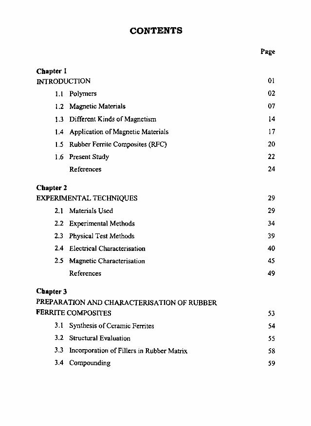
CONTENTS
Page
Chapter 1
INTRODUCTION 01
1.1 Polymers 02
1.2 Magnetic Materials 07
1.3 Different Kinds of Magnetism 14
1.4 Application ofMagnetic Materials 17
1.5 Rubber Ferrite Composites (RFC) 20
1.6 Present Study 22
References 24
Chapter 2
EXPERIMENTAL TECHNIQUES 29
2.1 Materials Used 29
2.2 Experimental Methods 34
2.3 Physical Test Methods 39
2.4 Electrical Characterisation 40
2.5 Magnetic Characterisation 45
References 49
Chapter 3
PREPARATION AND CHARACTERISAnON OF RUBBER
FERRITE COMPOSITES
3.1 Synthesis of Ceramic Ferrites
3.2 Structural Evaluation
3.3 Incorporation of Fillers in Rubber Matrix
3.4 Compounding
53
54
55
58
59

3.5 Determination of Cure Characteristics ofRFCs 61
3.6 Preparation ofTest Specimens 61
3.7 Conclusion 61
References 62
Chapter4
CURE CHARACTERISTICS AND MECHANICAL
PROPERTIES OF RUBBER FERRITE COMPOSITES 63
4.1 Introduction 63
4.2 Cure Characteristics 64
4.3 Mechanical Properties 73
4.3.1 Stress Strain Properties of Rubber Ferrite Composites 74
4.3.1.1 Natural Rubber based RFCs 74
4.3.1.2 Nitrile Rubber based RFCs 82
4.3.1.3 Abrasion Resistance 88
4.4 Conclusion 89
References 90
Chapter 5
DIELECTRIC PROPERTIES OF RUBBER FERRITE COMPOSITES 91
5.1 Introduction 91
5.2 Dielectric Measurements 92
5.2.1 Ceramic Samples 93
5.2.2 Dielectric Properties of Gum Natural Rubber Vulcanisate 96
5.2.3 Dielectric Properties of Gum Nitrile Rubber Vu1canisate 97
5.3 Dielectric Properties ofNR based RFCs 97
5.4 Dielectric Properties ofNBR based RFCs 123
5.5 AC Conductivity Studies 132
5.6 Conclusion 142
References 144

Chapter 6
MAGNETIC PROPERTIES OF RUBBER FERRITE COMPOSITES 147
6.1 Introduction 147
6.2 Magnetic Measurements 148
6.2.1 Ceramic Samples 148
6.2.2 Rubber Fenite Composites based on NR 150
6.2.3 Rubber Fenite Composites based on NBR 159
6.3 Tailoring of Magnetic Properties of RFCs 166
6.4 Conclusion 168
References 169
Chapter 7
SUMMARY AND CONCLUSION 170
7.1 Summary 171
7.2 Conclusion 174
7.3 Future Outlook 176
List of abbreviations and symbols 177
List of publications 180
Chapter1
INTRODUCTION
Rubber ferrite composites are magnetic polymer composites consisting of
ferrite fillers and natural/synthetic rubber matrix. These magnetic composites have
a variety of applications as flexible magnets, pressure / photo sensors and
microwave absorbers. One of the familiar applications of rubber magnets is the
refrigerator door seal. They are lightweight, soft, elastic, stable, flexible, easy to be
processed, energy saving and low cost.
Flexible magnetic composites can be prepared by embedding magnetic
fillers into polymer matrixes according to suitable recipes. The mouldability into
complex shapes is one of the advantages of these composite materials. Rubber
magnets thus produced by the incorporation of the magnetic materials into various
matrixes like natural and synthetic rubber have several advantages over the
conventional ceramic magnets, due to its flexible nature. Hence, they have the
POtential of replacing the conventional ceramic materials.
Polymers and magnetic materials play a very important role in our day to
day life. Both natural and synthetic polymers are truly indispensable to mankind.
The polymers, which include rubber, plastics and fibers, make life easier and more
COmfortable. They are used in the manufacture of textiles, building materials,
transportation, communication, packing materials, chairs, pipes, hoses, fancydecorative articles, toys etc.
Chapter 1
Magnetic materials are equally important and are widely used by man from
the very common machineries to the most sophisticated equipments. They are used
in instruments like television sets, telephones, refrigerators, washing machines,
vacuum cleaners, hearing aids, automobile parts, as permanent magnets in
computers, as magnetic sensors on credit cards and in theft control devices, in
magnetic recording media and various microwave absorbing devices. Magnetic
materials include metals, alloys and ceramics.
The permanent magnets play an important role in the science and technology
of the present day. Alnicos (AI, Ni & Co), barium ferrite and strontium ferrite
dominate the permanent magnet market. Of these barium ferrite and strontium
ferrite are frequently known as the "Ceramic Magnets". The rare earths have been
used in the new generation permanent magnets'. The discovery of Nd2Fel4B
magnets, in 1984, has ushered a new era for the rare earth-transition based
permanent magnets. Today's high-performance magnets are mostly made from
Nd2Fe t ..B.
1.1 POLYMERS
1.1.1 Natural Rubber
Natural rubber (NR) is obtained from the sap of a tree caned 'caoutchou' or
'weeping wood' and is botanicalty known as 'Hevea Brasiliensis', named after the
large forest tree, which is its outstanding source. The English term "Rubber" was
coined by Joseph priestly in 1770, since the material could erase pencil marks. The
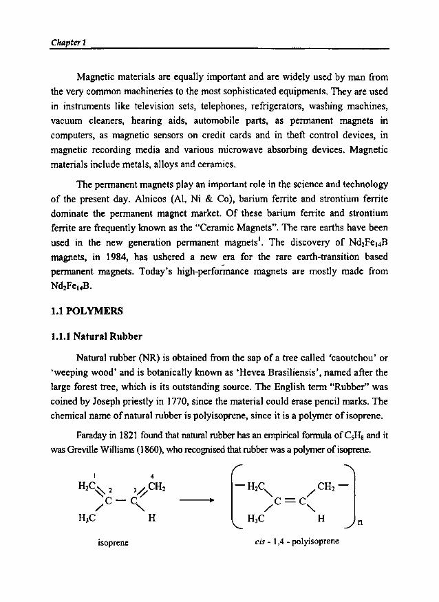
chemical name ofnatural rubber is polyisoprene, since it is a polymer of isoprene.
Faraday in 1821 found that natural rubber has an empirical formula ofCsHs and it
wasGrevil1e Wittiams(1860), who recognisedthat rubber was a polymerof isoprene.
isoprene cis - 1,4 - polyisoprene
n
Introduction
The polymer chains in natural rubber have a perfectly cis- l , 4 structure.
Hence the chemical name is eis-I, 4-polyisoprene2• The stereo regularity of the
natural rubber imparts a good regularity to the rubber chains, because of this the
natural rubber crystallises on stretching, resulting in high gum strength.
The raw natural rubber possesses considerable strength and appreciable
elasticity and resilience at room temperature. It is sensitive to hot and cold and
hence oxidises to a sticky product. For this reason rubbers have to be vulcanised
for achieving optimum properties. During the process of vulcanisation, cross
linking occurs between the long chain molecules to obtain a continuous network of
flexible, elastic chains. The three dimensional structure so produced restricts the
free mobility of the molecules and the product obtained have reduced tendency to
crystallise, improved elasticity, and substantially constant modulus and hardness
over a wide range of temperature. The number of crosslinks formed, also referred
to as degree of vulcanisation has an influence on the elastic and other properties of
the vulcanisate. Vulcanisation can be carried out by means of various chemical
reactions, depending on the chemical structure of the polymer. However, the most
common practice for unsaturated e1astomers such as natural rubber and the
synthetic polydienes involve the treatment with sulphur and its compound.
Vulcanisation with sulphur alone is a slow process and requires large amount
of sulphur, high temperatures and long heating periods. Hence accelerators are
used in combination with vulcanising agents to reduce the time and/or temperature
of vulcanisation. In certain cases accelerator activators and eo-activators are also
used. These form chemical complexes with the accelerators and increase the rate of
vulcanisation and improve the properties of the final vulcanisate.
The discovery of Hancock in 1824 that rubber could be masticated was of
greatest technical importance to the rubber industry. The addition of compounding
ingredients is greatly facilitated by this treatment, which is usually carried out on
two roll mills or in internal mixers or in continuous mixers. The process of
mastication is accompanied by a marked decrease in the molecular weight of the
rubber. When the mastication is complete, compounding ingredients are added, and
the rubber mix is prepared for vulcanisation. The details are cited elsewhere 3.

Chapter 1
For many applications, however, even the vulcanised rubbers do not exhibitsatisfactory tensile strength, modulus, stiffness, abrasion resistance and tear
resistance. These properties can be enhanced by the addition of certain fillers to the
rubber before vulcanisation. The fillers for rubber can be classified in two, inert
fillers and reinforcing fillers. Inert fillers like clay, whitings, talc etc make the
rubber mixture easier to handle before vulcanisation but have little effect on its
physical properties. Reinforcing fillers, however, improve the physical properties
of the vulcanised rubber. Carbon black is an outstanding reinforcing filler for both
natural and synthetic rubbers.
Rubbers that retain double bonds after vulcanisation, such as natural rubber,
styrene butadiene rubber and nitrile rubber, are sensitive to heat, light, and oxygen.
Unless protected with antioxidants (Maasen 1965), the rubbers age by an
autocatalytic process accompanied by an increase in oxygen content. As a result,
softening or embrittlement of rubber occurs indicating degradation. Many rubbersare sensitive to the attack by ozone, requiring protection by antiozonants (Cox
1965). Natural rubber is far more sensitive than most of the other elastomers toboth oxygen and ozone attack.
Rubber has certain unique properties, which makes it a useful material forproducts of commercial importance. In the vulcanised state it is elastic, and after
stretching it returns to its original shape and in the unvulcanised state it is plastic; i.e., it
flows under the effect ofheat or pressure. Rubber is a poor conductor of electricity andhence it is very valuable as an electrical insulator. Some of the applications include themanufacture of automobile tyres, mechanical goods, footwear, hoses, beltings,
adhesives and latex based products like gloves, foam rubber and thread.
1.1.2 Nitrile Rubber
Nitrile rubber, otherwise known by the generic name Buna-N or NBR, is a
special purpose synthetic rubber. It is a copolymer of butadiene and acrylonitrile.
The basic polymerisation reaction in the production of nitrile rubber is
CH2= CH-CH =CH2 + CH2 = CH
ICN
butadiene acrylonitrile copolymer unit

Introduction
Oil resistance is the most important property of nitrile rubber. NBR has good
resistance to oils, greases, petroleum hydrocarbons and other non-polar solvents.
Hence it is used in the manufacture of products like oil seals, a-rings, gaskets, fuel
and oil hoses, including high pressure hoses, for hydraulic and pneumatic
applications, friction covering, linings, containers, work boots, shoe soling and
heels, conveyor belts, in membranes, etc. The presence of the nitrile group
(C=N) on the polymer is responsible for this property. Nitrile rubbers are
sometimes blended with plastics to obtain useful products 4.
The commercially available nitrile rubbers differ from one another in three
aspects: acrylonitrile content, temperature employed for polymerisation, and
Mooney viscosity. However the acrylonitrile content is the one that has the most
profound affect on the properties of a vulcanised nitrile rubber, influencing its
resistance to oils and fuels.
The acrylonitrile (ACN) content varies usually from 20 - 50 % by weight and
accordingly NBR is classified in to three namely, low ACN content NBR with less
than 25%, medium with 25 - 35% and high content ACN NBR with 35 - 50%. The
oil resistance of the nitrile rubbers varies greatly with their composition. Increasing
the acrylonitrile content increases the oil resistance. For instance, when the ACN
content is 18%, the NBR has fair oil resistance and when the ACN content is 40%,
the polymer is extremely resistant to oil. This is because the incorporation of the
polar monomer acrylonitrile changes the polarity of the polymer. Most of the fuels
and lubricants are non polar and swell the non polar elastomer, such as NR, with a
resultant loss in properties. The amount of acrylonitrile affects several properties of
the elastomer. The properties like tensile strength, hardness, abrasion resistance, heat
resistance and gas impermeability increases with the increasing ACN content,
whereas other properties like resilience, low temperature flexibility, plasticiser
compatibility decreases with the increasing ACN content. Other properties affected
by monomer ratio are processability, cure rate, heat resistance and resistance to
permanent set. With increased ACN content processing is easier, cure rate is faster
and heat resistance better, but the resistance to permanent set decreases. Other
important characteristics, which can affect the properties of nitrile rubber, especially
the processing properties, are Mooney viscosity and gel content.
e
Chapter t
Basically nitrile rubbers are compounded much like natural rubber 5. The
compounding ingredients used are the same though they differ slightly in the
amount. Vulcanisation of nitrile rubber is usually accomplished with sulphur,
accelerator and zinc oxide and fatty acid as activator. In special cases peroxide may
also be used. Sulphur is less soluble in NBR than in NR and only small amounts
are used. But corresponding increases in the accelerators are required.
NBR shows no self-reinforcing effect, as there is no stress induced
crystallisation. Since it does not crystallise, reinforcing fillers are necessary to
obtain optimum tensile strength, tear strength and abrasion resistance. Carbon
black is the most widely used filler and the reinforcement is proportional to the
fineness of the black. Non black fillers used are various types of silica, calcium
carbonate, hard clay, talc and other inorganic fillers. Fine precipitated silica is most
reinforcing among the non black fillers. Semi-reinforcing fillers are also used for
obtaining suitable physical properties and jo bring down the raw material cost.
Plasticisers are used in almost all nitrile rubber compounds to improve
processability and low temperature flexibility. Generally used plasticisers are the
phthalate type esters.
Nitrile rubber requires age resistors in order to give longer service. Either the
amine or the hindered phenolic type antioxidants are generally used.
The important industrial applications of NBR include the manufacture of
cables for the petroleum, coal-mining and quarrying industries, transport,
shipbuilding, power distribution, domestic and miscellaneous applications't'. The
other fields that account for most of the uses of NBR are the automobile, aircraft,
oil, textile and printing industries.
It has already mentioned in this chapter that reinforcing fillers are required to
improve the properties of NBR. The present study involves the use of magnetic
fillers, namely barium ferrite and strontium ferrite, so as to obtain rubber magnets
or flexible magnets. High abrasion furnace black (HAF) is added as a reinforcing
filler along with ferrite fillers and its effect on different properties of the
vulcanisate are studied and are explained in subsequent chapters.

Introduction
1.2 MAGNETIC MATERIALS
Magnetic materials have wide range of applications, and these applications
impose certain requirements on the magnetic materials. Hence, the wide variety of
magnetic materials can be sharply divided into two groups, namely, magnetically
soft and magnetically hard8,9.
1.2.1 Soft Magnetic Materials
Soft magnetic materials have high permeability, low coercive force and
small hysteresis loss. They are easy to magnetise and demagnetise and have flux
multiplying power. Soft magnetic materials are used in applications requiring
frequent reversals of the direction of magnetisation.
Soft magnetic materials can be divided into four main groups, according to
their function. Heavy duty flux multipliers, light duty flux multipliers, square loop
materials, and microwave system components.
Heavy duty flux multipliers are used in the cores of transformers, generators,
and motors. The electrical steel, that form the cores of transformers, generators and
motors are subjected to alternating and rotating magnetic fields, and the
minimisation of the energy loss per cycle is a design objective. The electrical steel
is the cheapest magnetic material.
Light duty flux multipliers are the cores of small, special purpose transformers,
inductors etc used mainly in communications equipment. Soft ferrites and nickel-ironalloys fall in this class.
Square loop materials are used in computers and in magnetic amplifiers and
other saturable core devices. They include soft ferrites and nickel-iron alloys.
Microwave system components comprise soft ferrites and garnets. There are
various soft magnetic materials like Fe-Si or Fe-Ni alloys, ferrimagnetic oxides like
ferrites, Ferrites have the general formula M2tpe3+20 2'4 (where M2
+ is Ni2+, Fe2
+ etc.),
Soft magnetic materials are normally used for iron cores of transformers,
motors, and generators, where high permeability, low coercive force and smallhysteresis loss are required'",
Chaptnl
1.2.2 Hard Magnetic Materials
Hard magnetic materials have high coercivity, high remanence and large
hysteresis loss. They are difficult to magnetise and demagnetise. Hard magnetic
materials are used to produce permanent magnets11. The purpose of a permanent
magnet is to provide a magnetic field in a particular volume of space. A magnetic
field can be produced by current in a conductor or by poles in a magnet. For many
applications a permanent magnet is the better choice, since it provides a constant
field without the continuous expenditure of electric power and without the
generation of heat. A magnet is fundamentally an energy-storage device. This
energy is put into it when it is first magnetised and it remains in the magnet
indefinitely, if properly made and properly handled. Such magnets are called
'Permanent magnets' ..-
Hard magnetic materials are used as permanent magnets for various kinds of
electric meters, loudspeakers and in other apparatus for which high coercivity, high
remanence and large hysteresis loss are desirable.
Based on the composition and structural features, permanent magnetic
materials are classified into
1. Martensitic or quench hardened alloys.
2. Dispersion hardened alloys.
3. Work hardened alloys.
4. Order hardened or super lattice forming alloys.
5. Metallic powders, self bonded.
6. Metallic powders, bonded with a bonding agent
7. Ceramic powders, self bonded.
8. Ceramic powder, bonded with a bonding agent.
9. Miscellaneous, which possess some unusual features and not coming in the
above mentioned categories.
Hard magnetic materials include ferrites, alloy magnetic steels, permanent
magnet alloys, special alloys, carbon steels, magnetic steels, rare-earth based
Introduction
magnets, etc. The permanent magnets play a very important role in our day to day
life. Alnico (AI, Ni & Co), barium ferrite and strontium ferrite are the most widely
used permanent magnet materials. Recently, rare earth transition metal based
permanent magnets, especially Nd-Fe-B magnets having unique properties are used
in the modem technological devices",
1.2.3 Ferrites.
The field of magnetic oxides is one of the areas in magnetism, where
significant advances have been made since the beginning of the zo" century. Here
the development of ferrites and the advances made in this area are noteworthy.
Ferrites are a group of technologically important ferrimagnetic materials. The
advent of ferrites began with the search for magnetic materials of unusually high
resistivities to minimise eddy current losses. The term ferrites refers to all magnetic
oxides containing iron as the major metallic component 13. It is the systematic study
by Snoek" in 1946 that culminated in the introduction of magnetic ferrites having
technically and commercially viable properties. Research activities on ferrites in
the last five decades, has led to the development of these magnetic materials.
Ferrites are mixed metal oxides with iron (Ill) oxides as their main
components. They exhibit a substantial spontaneous magnetisation and phenomena
like magnetic saturation and hysteresis. Ferrites crystallise in three different crystal
structures, namely, spinels, garnets and magnetoplumbites,s-17.
Spine1 ferrites have a cubic structure with general formula MOFe20J. where
M is a divalent metal ion like Mn, Ni, Fe, Co, Mg etc. Garnets have a complex
cubic structure having a general formula LnJIIJFe20'2' where Ln'" ::: Y, Srn, Eu, Gd,
Tb, Dy, Ho, Er, Tm or Lu. The third type magnetoplumbite is having a hexagonal
structure with general formula M06Fe203, where M is a divalent metal such as Ba,
Sr and Pb. The most important in the group of magnetoplumbite is barium ferriteBa06Fe203.
Magnetically, ferrites are classified into two groups, namely, soft and hard'",
Further, depending on its symmetry, the magnetic ferrites fall mainly into two
groups, cubic and hexagonal's. Barium and strontium ferrites belong to the class of

Chapter 1
hexagonal ferrites. Both of these are hard ferrites as weU13.IS.17.19.23. They are
normally prepared using the ceramic technique24.34.
The ferrimagnetic materials have great commercial importance due to their
unique properties like large magnetisation values, high resistivity and low eddy
current losses. They have advantages such as applicability at higher frequency,
lower price and greater electrical resistance". The practical applications of ferrites
have been exploited by utilising these advantages.
Ferrites in general find extensive applications't'" in a number of devices like
inductor and transformer cores, antenna cores, magnetic amplifiers, deflection
yokes in television sets, hearing aids, computer peripherals, memory and switching
applications in digital computers and data processing circuits", modulators,
circulators, isolators, phase shifters, other high frequency devices and also for
various microwave applications'?' 4S-48. Other applications of ferrites involve the use
in temperature sensors, magnetostrictive decay lines, magnetic resonators, ferrite
filters", ferrite radiatorsso•s" ferrite power limiters and so on. They are usually
employed in the ceramic form. These ceramic magnets have the inherent drawback
that they are not easily machinable to obtain complex shapes.
1.2.3.1 Soft Ferrites
The ferrites, which are easy to magnetise and demagnetise, are termed as
soft ferrites. Soft ferrites have a cubic crystal structure. The general formula is
MOFe203. where M is a divalent metal ion like Mn, Ni, Fe, Mg etc. These ferrites
have saturation magnetisation (M,) value less than that of iron and its alloys and
have low dc permeability. So they are inferior to magnetic metals and alloys for
applications involving static or moderate-frequency fields. Non-magnetic zinc
ferrite is often added to increase the saturation magnetisation.
These ferrites have extremely high electrical resistivity with good magnetic
properties, so they can operate with virtually no eddy current loss at high
frequencies. This fact accounts for all the applications of soft ferrites.
The largest production of soft ferrites by weight is that of deflection yoke
rings" for picture tubes in television receivers. There are many other significant

Introduction
applications'O of soft ferrites such as recording heads, antenna rods, proximity
sensors, humidity sensors, interference suppression cores, etc.
1.2.3.2 Hard Ferrites
The ferrites, which are hard to magnetise and demagnetise, are termed as hard
ferrites. Hard ferrites have hexagonal crystal structure. The general formula is
M06Fe20], where M is a divalent metal ion like Ba, Sr and Pb. In the group of hard
ferrites, magnetoplumbites or M-type hexagonal ferrites (M06Fe20J) are widely
used in many technological applications due to their superior magnetic properties.
The most important among the hard ferrites is barium ferrite. It has a fairly
large crystal anisotropy (anisotropy constant, K = 3.3 X 10⁶ ergs I cm'), The Curie
point is 450°C. Barium ferrite was developed into a commercial magnet material in
1952 in Netherlands by the Philips Company, which called it ferroxdure. Some
American trade names are Indox, Ferrimag, etc. Strontium ferrite has almost
identical properties except that anisotropy constant is somewhat larger. In the
recent years, it has been replaced to some extent by strontium ferrite. Sometime the
general term 'hexaferrite' is used for both the materials.
Hexaferrites are widely used as permanent magnet materials" in applications
where a very high resistance to demagnetisation (high coercivity) is required and
the flux density does not need to be as high as in the metal magnetic materials.
Other important advantages are very low cost, lightweight, high chemical stability,
availability of the raw material and absence of eddy currents. One rapidly
increasing application of the hard ferrite involves its incorporation into rubber or
plastic matrixes thereby forming a versatile flexible magnet. Looking into the
industrial perspective, one can see that the total world production of hard ferrites is
almost the double that of the soft ferrites.
1.2.4 MagnetopIumbite structure
The hexagonal ferrites were discovered and investigated at the Philips
Research Laboratories". The determination of their structure by Braun" was the
1 1
Chapter 1
basis for understanding the crystallographic building principle and the magnetic
properties of these compounds. Of the several ferrimagnetic materials found with
the hexagonal structure, BaFe12019 (BaO.6FezOl)' often referred to, as barium
ferrite has the structure of naturally occurring mineral called Magnetoplumbite".
The term magnetoplumbite was coined' by a group of Swedish investigator",
Magnetoplumbite has the approximate formula, PbFeuMn3.sAlo.sTio.sOJ9' Its
structure was first described by Adelskod".
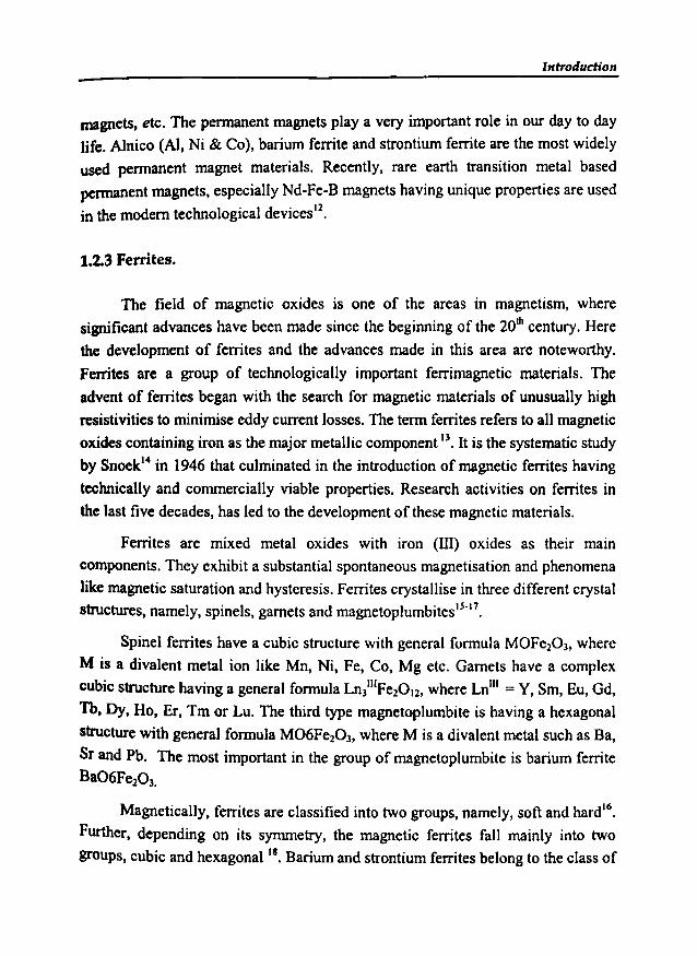
These classes of ferrites having composition M06Fe203 (M=Ba2+ I Sr+ I Pb2j ,
which is isostructural to mineral magnetoplumbite are commonly known as M-type
hexagonal ferrites'", Materials of this type are very strongly uniaxial with a high
value of K (anisotropy constant), and are used in making permanent magnets". The
magnetop1umbite structure can be visualised with help of figure 1.1. The atoms lie in
mirror planes containing the c-axis and in the figure; the atoms and symmetry
elements are shown for one such mirror plane. Atoms that do not lie on a three-fold
symmetry axis (the full vertical line) appear three times within a unit cell, in the same
plane perpendicular to the c-axis. Their other positions are readily obtained by
rotation of the figure about the three-fold axis through 120° and 240°.
In Figure 1.1, the 'blocks' S,R,S*, and R* are designated; the S-block has
the formula Fe60S and the R-block BaFe601l' Between Sand S*, and between R
and R· a 1800 rotation about the c-axis occurs. Thus the structure of the M-type
material may be written as SRS·R* or chemically 2(BaFeI20'9), i.e. two formula
units per unit cell.
Figure 1.1 depicts the unit cell of BaFeJ20J9. All atoms lie in mirror planes
containing the c-axis and atoms in one such plane are shown, together with the
blocks S, S·, Rand R* (after Braun 1957).
Introduction
l· x
00
[ 0-0-
0 • ironin 6vefold polition
0 0 0 ironin octahedral poJillon
~0 ironin lelnbedr.-lpoJlion
X
0 OOllY&etl
[0
~banum
0 - - - - lI'IUTor pline0 --c-axis.threefold rymmebyr x x centreoftymmelry
Fig 1.1 The unit cell of BaFeuOJ9
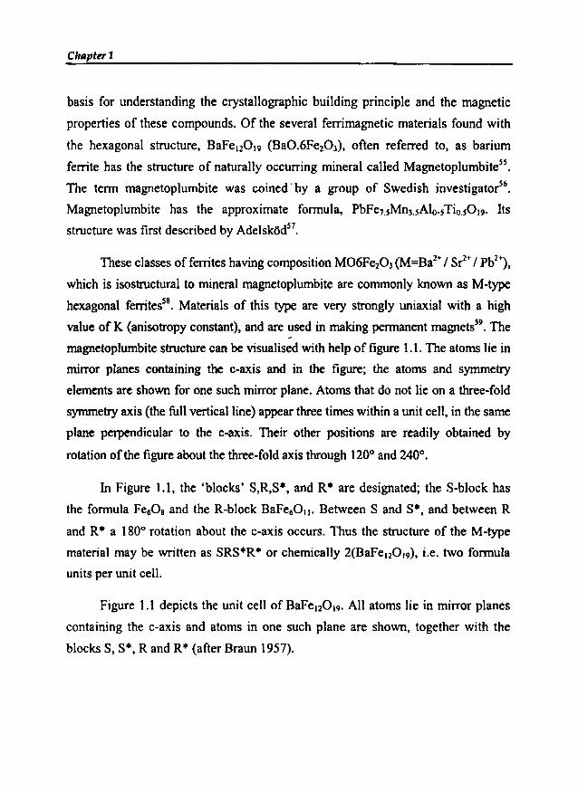
A third type of block, the T-block is shown in figure 1.2, where the
symbolism is that used in figure 1.1. The T-block consists of four oxygen layers
with an oxygen ion replaced by Ba2+ in each of the middle layers. The formula for
a T-block is thus Ba2FeaOJ4.
3+ 2+o Fe or M in octahedral position
3+ 2+o Fe or M in lelrahedralposition
o oxygen
~barium
o
x
o
oo
ooTblock
Fig 1.2 The T - block structure found in hexagonal iron oxides
Chapter 1
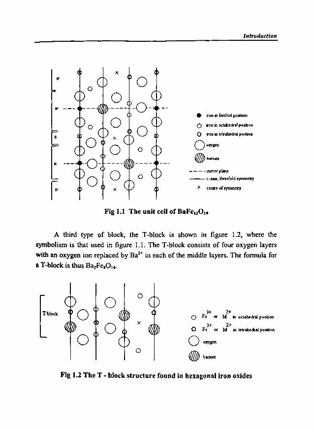
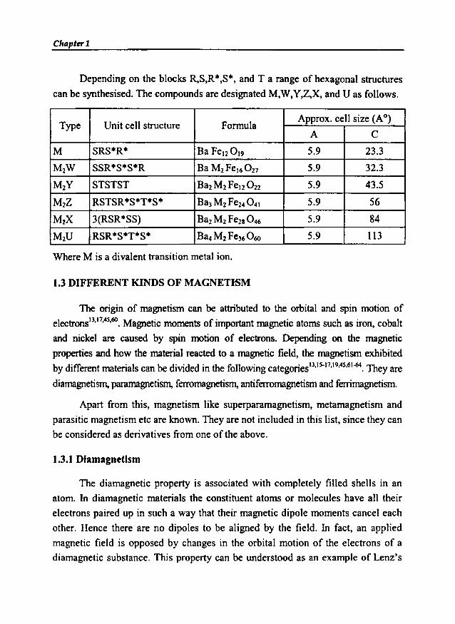
Depending on the blocks R,S,R·,S·, and T a range of hexagonal structures
can be synthesised. The compounds are designated M,W,Y,Z,X, and U as follows.
Type Unit cell structure FormulaApprox. cell size (A0)
A C
M SRS*R* Ba Fe12019 5.9 23.3
M1W SSR*S*S*R Ba M2Fel6027 5.9 32.3
M2Y STSTST Bal M1Fel20 22 5.9 43.5
M2Z RSTSR*S*T*S· Ba, M2 Fe24 0 41 5.9 56
MtX 3(RSR*SS) Ba2M2Fe28 0 46 5.9 84
M2U RSR*S*T*S· Ba4M2Fe36 0 60 5.9 113
Where M is a divalent transition metal ion.
1.3 DIFFERENT KINDS OF MAGNETISM
The origin of magnetism can be attributed to the orbital and spin motion of
electronsIJ.11.4s.60. Magnetic moments of important magnetic atoms such as iron, cobalt
and nickel are caused by spin motion of electrons. Depending on the magnetic
properties and how the material reacted to a magnetic field, the magnetism exhibited
by different materials can be divided in the following categories13,IS.17,19.4S,61-64. They are
diamagnetism, paramagnetism, ferromagnetism, antiferromagnetism and ferrimagnetism.
Apart from this, magnetism like superparamagnetism, metamagnetism and
parasitic magnetism etc are known. They are not included in this list, since they can
be considered as derivatives from one of the above.
1.3.1 Diamagnetism
The diamagnetic property is associated with completely filled shells in an
atom. In diamagnetic materials the constituent atoms or molecules have all their
electrons paired up in such a way that their magnetic dipole moments cancel each
other. Hence there are no dipoles to be aligned by the field. In fact, an applied
magnetic field is opposed by changes in the orbital motion of the electrons of a
diamagnetic substance. This property can be understood as an example of Lenz's
Introduction
law, which states that an applied magnetic field produces a field that opposes its
cause. The diamagnetic materials have the relative permeability J.lr < I and
susceptibility X is a small negative value. The negative value of diamagnetic
materials is in accordance with the Lenz's law. Super conductors are perfect
diamagnets with X=-1
There are various diamagnetic materials; the strongest among them are
metallic bismuth and organic molecules such as benzene. Other examples include
metals like Cd, Cu, Ag, Sn, and Zn.
1.3.2 Paramagnetism
Paramagnetic substances have intrinsic permanent magnetic moments. When
an external field is applied, they tend to align themselves parallel to the field,
thereby intensifying the lines of force in the direction of the applied field. This
result in an over all magnetic moment that adds to the magnetic field.
Paramagnetism is independent of the applied field but is temperature dependent.
For ideal paramagnetic materials, the relative permeability J.lr > I and
susceptibility X is small positive and varies inversely with the absolute temperature.
Paramagnets are governed by Curie's law, which states that X is proportional to
l/T; Tbeing the absolute temperature.
Paramagnetic materials usually contain transition metals or rare earth
materials that posses unpaired electrons.
1.3.3 Ferromagnetism
A ferromagnetic substance has a net magnetic moment even in the absence
of the external magnetic field. This is because of the strong interaction between the
magnetic moments of the individual atoms or electrons in the magnetic substance
that causes them to line up parallel to one another. When the many individual
magnetic dipole moments produced in a material are appreciable, there can be long
range interactions. This results in large scale areas ofmagnetism called domains. In
ferromagnetic materials, the dipoles within a domain are all aligned and the
domains tend to align with an applied field. The energy expended in reorienting the

Chapter 1
domains from the magnetised back to the demagnetised state manifests itself in a
fag in response, known as hysteresis.
For ferromagnetic materials, the relative permeability ~ > 1 and
susceptibility X is large positive and varies with the absolute temperature. They
obey the Curie - Weiss law,
X C where C ande are Curie Weiss constants.= (T-8)'
An important property of ferromagnets is the Curie temperature, named after
the French physicist Pierre Curie, who discovered it in 1895. Above the Curie
temperature ferromagnets become paramagnets, since there is sufficient thermal
energy to destroy the interaction between atoms that creates domains. i.e.
ferromagnetic materials, when heated, eventually lose their magnetic properties.
This loss becomes complete above the CUrie temperature. The Curie temperature of
metallic iron is about 770°C.
Ferromagnetism is exhibited mostly by metals and alloys. Iron, Cobalt and
Nickel are all examples of ferromagnetic materials. Chromium dioxide is another
material that exhibits ferromagnetism.
t .3.4 Anti ferromagnetism
Antiferromagnetism IS a weak magnetism, which is similar to
paramagnetism in the sense of exhibiting a small positive susceptibility. The
substances in which the magnetic moments interact in a way, such that it is
energetically favorable for them to line up antiparallel are called antiferromagnets.
The behavior of antiferromagnetic substances to an applied magnetic field
depends up on the temperature. At low temperatures, the arrangement of the atomic
dipoles is not affected, and the substance does not respond to an applied magnetic
field. When the temperature is increased, some atoms are loosened and align with
the magnetic field. This results in a weak magnetism in the substance.

Introduction
There is a temperature analogous to Curie temperature called the Neel
temperature, above which antiferromagnetic order disappears. Above the Neel
temperature the substance becomes paramagnetic. Most antiferromagnetics are
ionic compounds, namely, oxides, sulphides, chlorides and the like. MnO, Cr20 J.
MnS, NiCh etc are some examples of antiferromagnetic materials.
1.3.5Ferrimagnetism
The term 'Ferrimagnetism' was proposed by Neel in order to explain the
magnetism of ferrites. Ferrimagnets are a form of antiferromagnet in which the
opposing dipoles are not equal so they do not cancel out. Just like ferromagnetics,
fcrrimagnetic materials exhibit a substantial spontaneous magnetisation, which
makes them industrially important. Ferrimagnets are good insulators, making them
veryuseful in preventing energy losses due to eddy currents in transformers.
At a certain temperature, called the Curie point, the arrangement of the spins
become random, and the spontaneous magnetisation vanishes. Above this Curie
point, the substance exhibits paramagnetism. The most important ferrimagnetic
substances are ferrites and the naturally occurring mineral magnetite.
1.4 APPLICATION OF MAGNETIC MATERIALS
Man has used magnetic materials for thousands of years. Today they play an
important role and are widely spread in daily life applications. For instance, they
are found in numerous products such as home appliances, electronic products,
automobiles, communication and data processing devices and equipments. These
materials include metals, metal oxides, alloys, ionic compounds, ceramics andpolymers.
The most important use of magnets at home is in the electric motors. All
electric motors work on the principle of an electromagnet. These motors run the
pumps, fans, refrigerators, vacuum cleaners, washing machines, mixers etc.
AUdiotape and videotape players have electromagnets called heads that record and
read information on tapes covered with tiny magnetic particles. Magnets in speakers
Chapter 1
transform the signal into a sound by making the speakers vibrate. An electromagnet
called a deflection yoke in TV picture tubes helps form images on a screenlO,14.
Magnets are also used in certain modern switches and other electrical accessories.
An important engineering application of magnetic materials is as permanent
magnets I6•6S
• The earliest and for a long time the only; application of the permanent
magnet was in the compass needle. Today the application of the permanent magnet,
in industry, transportation, in the automobile, aircraft, shipbuilding, power
distribution etc form a long list. The magnets used in the industry include
electromagnetic powered devices such as crane, cutters, fax machines, computers
etc. They are also used in electric indicators, integrating and recording meters,
process variable sensors, transmitters, analysers and controllers, alarm monitoring
systems in control panels and so on. In transportation, systems that use
electromagnetic materials are trains, "tractors, subways, trolleys, monorails,
escalators, elevators, cycle dynamos etc. Scientists and engineers have developed
trains that use electromagnetism to float it above the track. They use the force of a
magnet to levitate the train. It eliminates friction so it has an advantage of higher
speeds over ordinary trains. In the automobile, magnets are used in the magneto
ignition system, parts in wipers, horns, starters, switches, induction motors, etc. In
the power sector, the major application of magnets is in the generators and
transformers. Generators in power plants rely on magnets like the ones found in
electric motors to produce electricity. Transformers are devices that use
electromagnetism to change high voltage electricity to low voltage electricity
needed in homes and industries.
The branch of magnetism finds lots of application in science and medicine.
The bending magnets are very powerful magnets that help control beams of atomic
particles, which are boosted into high speed devices called particle accelerators. An
important application of magnetism in medicine is magnetic resonance imaging
(MRI), The technique is used primarily in medical settings to produce high quality
images of the inside of the human body. MRI is based on the principles of nuclear
magnetic resonance (NMR), a spectroscopic technique used by scientists to obtain
microscopic, chemical and physical information about molecules. The principle of

Introduction
MRI is applicable in the human body because we are all filled with small biological
magnets, the most abundant and responsive of which is the nucleus of the hydrogen
atom, the proton. The principle of MRI takes advantage of the random distribution
of protons, which possess fundamental magnetic properties. Magnetic bottles are
created to hold plasmas, which is so hot they would melt any container made of
ordinary material, so they hold it in a magnetic field.
Magnetic materials are used at both radio and microwave frequencies. There
are numerous applications below microwave frequencies. Some of these are used
as cores in inductors, flyback transformers, magnetic memories and switching
devices. The memory and switching applications in digital computers and data
processing circuits involves the use of microsecond pulses for transmitting, storing,
and reading information expressed in a binary code. Other non-microwave
applications are transformers and tuned inductors. Applications at the microwave
frequencies include the use in making microwave devices such as waveguide
isolators, which can transmit in one direction but attenuate in the other. It is also
used in various polarization rotators, resonance isolators, modulators, phase
shifters, circulators and as microwave gyrators.
Composites magnetic materials find large variety of applications because of
their remarkable properties. They are used in magnetic recording media, color
imaging, magnetic memories for computers, magnetic fluids, magnetic
refrigeration, etc. Magnets based on rubber ferrite composites find applications in
many devices because of their easy mouldability, flexibility and microwave
absorbing properties.
Magnetic ceramics or ferrites are very well established groups of magnetic
materials. Research activity on ferrites in the last five decades, has led to
development of these magnetic materials. Magnetic ceramics participate in virtually
every area of application. Even though magnetic ceramics are very well established,
improvements and innovations continue to take place; many new and exciting
applications, theories and preparation technologies are currently under development.
Hence the study of ferrites and magnetic composites assumes significance.
Chapter 1
I.S RUBBER FERRITE COMPOSITES (RFC)
A composite can be defined as the material created when two or more
distinct components are combined". These composite materials, which comprise
two physically distinct phases - a soft material and a hard reinforcing material.
enjoy the conjoint properties of both the phases. If formulated and fabricated
properly, composites can offer a combination of properties and a diversity of
applications unattainable with metals. ceramics. or polymers alone. Thus
composites have exceptional and superior properties that surpass the performance
of the individual components. There are natural (e.g, wood. teeth, bone etc.) as well
as synthetic (e.g. alloys) composites. In polymers they include copolymers and
blends, reinforced plastics and material such as carbon black and non-black
reinforced rubber vulcanisate.
Polymer matrix composites are- often termed as advanced composite
materials. These are the commonly used advanced composites, which can be
fashioned into a variety of shapes and sizes. They provide great strength and
stiffness along with a resistance to corrosion.
Composite magnetic materials (composites with two or more phases where
at least one phase is magnetic) have the advantage that their physical properties can
be modified so as to tailor materials for various applications.
In magnetic polymer composites. both the magnetic filler and the polymer
matrix chosen affect processability and physical properties of the final product.
Hence the proper selection of fillers and the matrix is very important to tailor make
composites for various applications. The polymer must have appropriate physical
properties and reasonable stability. Also factors like percolation limits and nature
of the matrix namely saturation! unsaturation / polarity of the rubber all influences
the final properties of the composites. The macroscopic parameters of the
composites like modulus and tensile strength would be influenced by the
interaction between the filler and the matrix. The role of fillers in modifying the
properties of the composites is to be understood properly for developing RFCs with
the required properties for various applications. Thus a systematic study of these
composites would be very useful to design materials for specific applications.
1"traduction
Flexible rubber magnets and plastic magnets are usually made by mixing
ferrite with an appropriate polymer using suitable compounding ingredients
according to specific recipe9,67.68. Flexible magnets with appropriate magnetic
properties can be made by a judicious choice of magnetic fillers. The impregnation
of magnetic filler into the matrix not only imparts the magnetic properties but also
modifies the dielectric properties of the composites.
The incorporation of ferrite powders in natural or synthetic rubbers produce
flexible ferrites or rubber ferrite composites10,69·71• which has many novel
applications as magnets. For instance. the resistance to mutual demagnetisation is
as good as that of sintered isotropic ferrite. and the brittleness is replaced by
flexibility. Compared with alloy magnets the holding power is low. but it is
sufficient for many purposes. where cheapness and adaptability are more
important. Rubber ferrite composites (RFCs) can be synthesised by the
incorporation of ferrite powders in natural or synthetic rubber matrixes. Both the
soft and hard ferrites can be embedded in the polymer matrix. Soft ferrites like
nickel-zinc ferrite. manganese-zinc ferrite have been incorporated in the polymer
matrixes (both natural and synthetic) to produce RFCs72• The incorporation of hard
ferrites in the elastomer matrix can not only bring economy but also produce
flexible permanent magnets which find extensive applications':".
Rubber Ferrite Composites have enormous application potential in electrical
and. electronic industries in different forms. These involve the use in magnetic
memories for computers, magnetic fluids. magnetic refrigeration. magnetostrictive
transducers. color imaging and in many applications that can be achieved by ceramic
materials. The rubber ferrite composites are useful as microwave absorbing materials
due to its dielectric properties and design flexibility. Some of these materials are used
as electromagnetic wave absorbers in the VHF and UHF bands7s•76
• Thus they find
applications in the microwave and radar technology applications.
The addition of carbon black is known to reinforce the matrixes; moreover,
earlier studies have indicated that the addition of fillers like carbon black on rubber
ferrite composites enhances the microwave absorbing properties of the composites":".
Therefore. studies pertaining to the incorporation of carbon black along with
magnetic fillers in elastomer matrixes are interesting and assume significance.
Chapter 1
1.6 PRESENT STUDY
Composites can offer a combination of properties and a diversity of
applications unobtainable with the individual components. This is exploited in the
preparation of rubber ferrite composites. Here the useful properties of the polymer
matrix and the ferrite filler are advantageously used for the production of RFCs.
The matrix and the filler are chosen to obtain the optimum properties for specific
applications. The magnetic polymer composites have the advantage that their
physical properties can be modified so as to tailor make materials for various
applications.
In the present study the hexagonal hard ferrite, namely barium ferrite,
BaFe12019 (BaF) and strontium ferrite, SrFe12019 (SrF) have been prepared by the
conventional ceramic techniques and characterised by XRD. These pre
characterised magnetic filler are then incorporated into two different matrixes,
namely natural rubber (NR) and nitrile rubber (NBR) separately. The incorporation
is carried out according to a specific recipe and for various loadings of ferrite filler
and N330 (HAF) carbon black. The hard ferrites are selected, to produce flexible
permanent magnets. Possible value addition to the abundantly available natural
resource, natural rubber is also aimed at by undertaking this study. The nitrile
rubber is chosen considering its superior and special purpose applications. The
structural, magnetic, mechanical and electrical characterisation of these ceramic
filler as well RFC have been carried out and the results are correlated.
The main objectives of the present work can be summarised as follows:
~ Preparation ofbarium ferrite and strontium ferrite using ceramic technique.
~ Characterisation of the prepared ferrites using X-ray diffraction technique
(XRD).
~ The incorporation of these ferrites into elastomer matrix to produce rubber
ferrite composites (RFC).
~ Evaluation of the processability and mechanical properties of the RFCs.
??

Introduction
> Analysis of the dielectric properties of the ceramic BaF and SrF and RFCs
at various frequencies and temperatures
> Magnetic characterisation of the prepared fenite and RFCs using Vibration
Sample Magnetometer (VSM)
> Study the effect of loading of ferrite fillers on processing, mechanical,
dielectric and magnetic properties of RFCs.
> Study the effect of carbon black on the processing, mechanical, dielectric
and magnetic properties of RFCs.
> Correlation of properties.
Chapter 1
REFERENCES
1. Muller K.H, G. Krabbes, J. Fink, S. Grub. A. Kirchner,.G. Fuchs, L. Schultz, J.
Magn. Magn. Mater, 226.230 (2001) 1370-1376.
2. Maurice Morton, 'Rubber Technology', 3td edition, 1995, Van Nostrand
Reinhold Company, New York.
3. Fred W Billmeyer Jr, 'Textbook of Polymer Science', 4 fh edition, 1994, John
Wiley & Sons, Inc., New York.
4. Brydson 1. A, 'Plastic Materials', 5111 edition, 1989, Butterworth Scientific, London.
5. Werner Hofmann, 'Rubber Technology Handbook', 1989, Hanser Publishers,
Munich Vienna, New York.
6. Colin W. Evans, 'Developments in Rubber and Rubber Composites - 2', 1983,
Applied Science Publishers Ltd, London and New York.
7. Penn W. S, 'Synthetic Rubber Technology', Vol-l, 1960, Staples Printers Limited.
8. "Doug" DeMaw. M. F, 'Ferromagnetic-Core Design and Application Handbook',
1981, Prentice-Hall, Englewood Cliffs, New Jersey.
9. John Delmonte, 'Metal-Filled Plastics', Reinhold Publishing Corporation,
New York.
10. Snelling. E.C and A.D. Giles, 'Ferries for Inductors and Transformers',
Research Studies press Ltd, John Wiley & Sons Inc. New York.
11. Alex Goldman, 'Modem Ferrite Technology', 1990, Ferrite Technology worldwide,
Inc., Published by Van Nostrand Reinhold, 115 Fifth Avenue, New York.
12. Krishnamurty. Nand Ashok Kumar Sun, 'Rare Earths and Their Role in
Modern Life', 2001, Published by Indian Association for Radiation Protection,
BARC, Trombay, Mumbai.
13. Smit. J and H.PJ. Wijn, 'Ferrites', 1959, Philips Technical library.
14. Snoek, J.t. 'New Developments in Ferromagnetic Materials', 1947, Elsevier
Publishing Company, Inc., New York-Amsterdam.
IS. Cullity B.D, 'Introduction to Magnetic Materials', 1972, Addison- Wesley
Publishing Company, Inc., Philippines.

Introduction
16. Soshin Chikazumi and Stanley H.Charap: 'Physics of Magnetism', 3rd Edn,
1964, John Wiley & Sons, Inc., New York.
17. Murthy V.R.K and B. Viswanathan, 'Ferrite Materials', 1990, Science and
Technology, Narosa Publishing House.
18. Cullity. B.D, 'Elements of X-ray diffraction', 2nd Edn, 1978, Addison-Wesley
Publishing Company, Inc., Philippines.
19. Hadfield D, 'Permanent Magnets and Magnetism', 1962, John Wiley and sons,
Inc., London.
20. Hiroaki Nishio, Hitoshi Taguchi, Fumihiko Hirata and Taku Takeishi, IEEE,
Trans. Magn, 29, 6 (1993).
21. Xinyong Li, Gongxuan Lu, Shuben Li, 1. Mater. Sci. Lett.,lS (1996) 397-399.
22. Wartewig P, K. Melzer, M. Krause and R. Tellgren, J. Magn. Magn. Mater.,
140-144 (1995) 2101-2102.
23. Wang J. F, C. B. Ponton and I. R. Harris, J. Magn. Magn. Mater., 234 (2001)
233-240.
24. Benito. G, M. P. Morales, J. Reequena, V. Raposo, M. Vazquez, and 1. S. Moya,
J. Magn. Magn. Mater., 234 (2001) 65-72.
25. B. V. Bhise, M.B.Dangare, S.APatil, S.R.Sawant, J. Mater. Sci. Lett. 10 (1991) 922.
26. Sawadh. P. S, and Kulkami. D.K, Materials Chemistry and physics, 63 (2000)
170-173.
27. Ahmed. M. A, Phys. Stat. Sol. A 111 (1989) 567.
28. Valenzuela R, 'Magnetic Ceramics', 1994, Cambridge, Cambridge University Press.
29. Haneda. K, and Kojima. H, J. Amer. Ceram. Soc., 57 (1974) 68.
30. Sung-Soo Kim and Dae-Hee Han, IEEE Trans. Magn., 30, 6 (1994).
31. Daniels. J.M and Rosencwaig, Can.J.Phys. 48 (1970) 381.
32. Leung. L.K, Evans. BJ, and Morrish. AH, phys, Rev. B 8 (1973) 29.
33. PatH. AN, PatH. M.G, Patankar. K.K, Mathe. v.i, Mahajan. R.P and Patil. S. A,
Bull. Mater. Sci., 23, 5 (2000) 447-452.
34. Murthy. S.R, Bull. Mater. Sci., 24, 4 (2001) 379-383.
Chapter 1
35. Mitsuo Sugimoto, 1. Amer. eer. Soc., Sugimoto, 82, 2 (1999) 269- 280.
36. Ronald F. Soohoo, 'Theory and Applications of Ferrites', 1960, Engle wood
Cliffs, Prentice-Hall, Inc., New Jersey.
37. Kato, V. and Takei. T, 'Permanent oxide magnet and its characteristics', J.
Instn. Elect. Engrs, Japan, 53 (1933) 408.
38. Kawai. N, 'Formation of a solid solution between some ferrites', J. Soc. Chem.
Ind. Japan, 37 (1934) 392.
39. Snoek. J. L, 'Magnetic and electrical properties of the binary systems
MO.Fe20)·,3 (1936) 363, Physica, Amsterdam.
40. Owens. C.D, 'A survey of the properties and applications of ferrites below
microwave frequencies', Proc. Inst. Radio. Engrs., 44 (1956) 1234-1248.
41. Snelting. E. C, 'Ferrites for linear applications', Part 1, Properties. IEEE
Spectrum. 9, 1 (1972) 46-47.
42. Watanabe. H, Iida. Sand Sugimoto, 'Ferrites', Proceedings ofICF3 (1981) M.
Centre for Academic Publications, Japan.
43. Thomas. G, 'Advances in ferrites', VoU ibid.197 (1989).
44. Papian W.N, Proc. I.R.E., (1952) 475.
45. Benjamin Lax, Kenneth J Button, 'Microwave Ferrites and Ferrimagnetics',
1962. Mc Graw-Hill Book Co.
46. Bate and Alstad, IEEE Trans, Magn., 5 (1969) 823-839.
47. limura, Tsutomu, (Magn.Electron.Mater.Res.Lab; Hitachi Met.Ltd., Kumagaya,
Japan 360), Zairyo Kagaku, 27, 3 (1990) 179-187.
48. Shin. 1. Y and J. H. Oh, IEEE Trans. Magn., 29, 6 (1993) 3437-3439.
49. Nelson C.E, "Ferrite-Tunable Microwave Cavities and the Introduction of a
New Reflectionless, Tunable Microwave Filter," proc. I.R.E., 44 (1956) 1449.
50. Angelakos D.J and M.M. Korman, "Radiation from Ferrite-Filled Apertures".
Proc. I.R.E. (1956) 1463.
51. Tyras G and G. Held, "Radiation from a Rectangular waveguide Filled with
Ferrite", Trans. !.R.E. on Microwave Theory and Techniques. MTT-6, 3
(1958) 268.
Introduction
52. Barten, P.G,J. and Kaashoek, J. IEEE Trans. Consum. electron., CE-24, 3
(1978) 481-488.
53: van den Broek, C.A.M. and Stuijts, A.L. Ferroxdure. Philips Tech. Rev., 37, 7
(1977) 157-175.
54. Braun P. B, 'The crystal structures of a new group of ferromagnetic
compounds', Philips Res. Repts., 12 (1957) 491-545.
55. Jan Smit, 'Magnetic Properties of Material', 13,29 (1971) Inter University
Electronics series, McGraw~Hill Company.
56. AminoffG, Geol. Foren. Stockholm, Forth, 47 (1925) 283.
57. Adelskdd V, Arkiv Kemi. Mineral. Geol., 12A (1938) 1-9.
58. Standley K. J, 'Oxide Magnetic Materials', 2nd edition, 36 (1972) Clarendon
Press, Oxford.
59. Craik D. J and R. S. Tebble, 'Ferromagnetism and Ferromagnetic Domains',
1965, North-Holland Publishing Company, Amsterdam.
60. Daniel C. Mattis, The theory of Magnetism, 1965, Harper and Row Publishers
New York.
61. Crangle. J, The Magnetic Properties of Solids, 1977, Edward Arnold
Publishers Ltd.
62. KeerRV, Principlesof solid state physics, 1993,Willey EasternLtd.,New Delhi.
63. Ami E. Berkowitz and Eckart Kneller, Magnetism and Metallurgy, 1969,
Academic Press Inc.
64. Brailsford. F, Physical principles of magnetism, 1966,0 Van Nostrand Co. Ltd.
65. Holzbock. W. G, 'Instruments for measurements and control' 2nd edition,
1962, Van Nostrand Reinhold Company, New York.
66. Encyclopedia of Polymer Science and Engineering, Vol.3.
67. Katz R 8 and J. V. Milewski, 'Handbook of Reinforcement of Plastics', 1978,
Vannostrand Reinhold, New York.
68. Jozef Slama, Anna Gruskova, L'udovit Keszegh, Mojmir Kollar, IEEE Trans.
Magn., 30, 2 (1994) 1101-1103.

Chapter 1
69. Safari Ardi M, Dick Wand McQueen D.H, Plastic Rubber and Composites
Processing Applications, 24 (1995) 157-164.
70. Anantharaman M.R, S. Jagatheesan, S. Sindhu, K.A. Malini, C. N.
Chinnasamy, A. Narayansamy, P. Kurian and K. Vasudevan, Plastic Rubber
and Composites Processing Applications, 27, 2 (1998) 77-81.
71. Anantharaman M.R, S. Sindhu, S. Jagatheesan, K.A. Malini and Philip
Kurian, Journal ofPhysics D Applied Physics 32 (1999) 1801-1810.
72. Anantharaman. M.R, K.A.Malini, S.Sindhu, E.M. Mohammed,
S.K. Date, P.A.Joy and Philip Kurian, Bull. Mater. ScL, 24, 6, (2001)
623-631.
73. Praveen Singh & T.C. Goel, Indian 1. Pure and Appl Phys., 38 (2000) 213-219.
74. Anantharaman M. R, P. Kurian, B. Banerjee, E. M. Mohammed, and M.
George, Kautschuk Gummi Kunststoffe, Germany, 6,49 (1996) 424- 426.
75. Grunberger W, B. Springmann, M. Brusberg, M. Schmidt and R. Jahnke, J.
Magn. Magn. Mater., 101 (1991) 173-174.
76. Naito Y and K. Suetake, IEEE Trans. Micro Wave Theory and Tech., MTT
19,1 (1971) 65-72.
77. Mirtaheri S.A, J.Yin, H. Seki, T. Mizumoto and Y.Naito, Trans. IEICE, 72, 12
(1989) 1447-1452.
78. Dishovski N, A.Petkov, Iv. Nedkov and Iv.Razkazov: IEEE Trans Magn., 30,
2 (1994) 969-970.
79. Ganchev S.I, J. Bhartacharyya, S. Bakhtiari, N. Quaddoumi, D. Brabndenburg
and R.Zoughi, IEEE Trans. Microwave Theory and Tech., 42, 1 (1994) 18-24.
80. Kim S.S, S.B.Jo, K.I.Gueon, K.K.Choi, J.M.Kim and K.S.Chum: IEEE Trans.
Magn., 27, 6 (1991) 5462-5464.
81. Kwon H.J, J.Y. Shin and J.H.Oh: J. Appl. Phys., 75, 10 (1994) 6109-6111.
Chapter2
EXPERIMENTAL TECHNIQUES
The materials used and the experimental procedures adopted in the present
investigations are given in this chapter.
2.1. MATERIALS USED
2.1.1 Elastomers
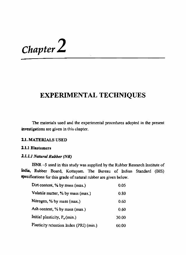
2.1.1.1 Natural Rubber (NR)
ISNR -5 used in this study was supplied by the Rubber Research Institute of
India, Rubber Board, Kottayam. The Bureau of Indian Standard (BIS)
specifications for this grade of natural rubber are given below.
Dirt content, % by mass (max.) 0.05
Volatile matter, % by mass (max.) 0.80
Nitrogen, % by mass (max.) 0.60
Ash content, % by mass (max.) 0.60
Initial plasticity, P, (min.) 30.00
Plasticity retention Index (PR!) (min.) 60.00
Chapter 2
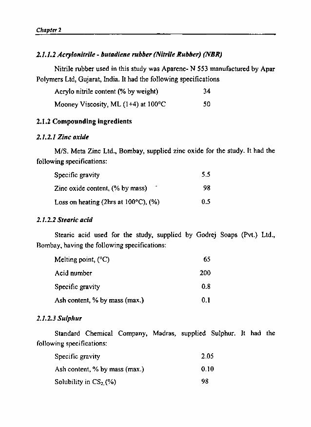
2.1.1.2 Acrylonitrile - butadiene rubber (Nitrile Rubber) (NBR)
Nitrile rubber used in this study was Aparene- N 553 manufactured by Apar
Polymers Ltd, Gujarat, India. It had the following specifications
Acrylo nitrile content (% by weight) 34
Mooney Viscosity, ML (1+4) at 100°C
2.1.2 Compounding ingredients
2.1.2.1 Zinc oxide
50
M/S. Meta Zinc Ltd., Bombay, supplied zinc oxide for the study. It had the
following specifications:
Specific gravity
Zinc oxide content, (% by mass)
Loss on heating (2hrs at 100°C), (%)
2.1.2.2 Stearic acid
5.5
98
0.5
Stearic acid used for the study, supplied by Godrej Soaps (Pvt.) Ltd.,
Bombay, having the following specifications:
Melting point, (0C)
Acid number
Specific gravity
Ash content, % by mass (max.)
2.1.2.3 Sulphur
65
200
0.8
0.1
Standard Chemical Company, Madras, supplied Sulphur. It had the
following specifications:
Specific gravity
Ash content, % by mass (max.)
Solubility in CS2•(%)
2.05
0.10
98

Experimental Techniques-2.1.2.4 Fillers
2.1.2.4. 1 Carbon black
High abrasion furnace black (HAF N-330) used in these experiments was
supplied by M/S. Philips Carbon Ltd., Cochin and had the following specification.
Appearance Black granules
OBP absorption, (eel 100 g)
Pour density, (glee)
Iodine number
Loss on heatinglhr (max) at 125°C, (%)
2.1.2.4.2 Barium Ferrite
102 ±5
0.39
82
2.5
Barium ferrite (BaF) prepared by the ceramic technique was used for the
preparation of RFCs.
2.1.2.4.3 Strontium Ferrite
Strontium ferrite (SrF) used for the preparation of RFCs was prepared by theceramic technique
2.1.2.5 Accelerator
2.1.2.5.1 N - Cylohexyl Bem.thiaul Sulphenamide (CBSj
The sample had the following specifications:
Ash content, % by mass (max.) 0.5
Moisture % by mass (max.) 0.5
Specific gravity 1.27
2.1.2.6 Plasticisers
2.1.2.6.1 Aromatic oil
Aromatic oil supplied by Hindustan Organic Chemicals having the followingspecifications was used for the study.
Chapter 2
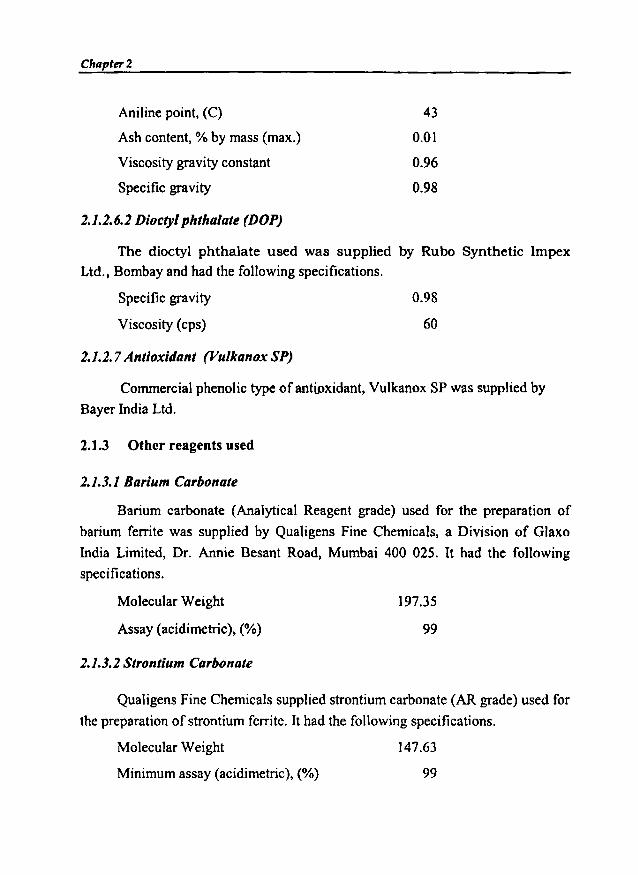
Aniline point, (C)
Ash content, % by mass (rnax.)
Viscosity gravity constant
Specific gravity
2.1.2.6.2 Dioctyl phthalate (DOP)
43
0.01
0.96
0.98
The dioctyl phthalate used was supplied by Rubo Synthetic Impex
Ltd.• Bombay and had the following specifications.
Specific gravity 0.98
Viscosity (cps)
2.1.2.7 Antioxidant (Vulkanox sPy
60
Commercial phenolic type ofantioxidant, Vulkanox SP was supplied by
Bayer India Ltd.
2.1.3 Other reagents used
2.1.3.1 Barium Carbonate
Barium carbonate (Analytical Reagent grade) used for the preparation of
barium ferrite was supplied by Qualigens Fine Chemicals, a Division of Glaxo
India Limited, Dr. Annie Besant Road, Mumbai 400 025. It had the following
specifications.
Molecular Weight
Assay (acidimetric), (%)
2.1.3.2 Strontium Carbonate
197.35
99
Qualigens Fine Chemicals supplied strontium carbonate (AR grade) used for
the preparation of strontium ferrite. It had the following specifications.
Molecular Weight
Minimum assay (acidimetric), (%)
147.63
99

Experimental Techniques
2.1.3.3Ferrous Sulphate
Qualigens Fine Chemicals supplied ferrous sulphate (AR grade) used for the
preparation of barium and strontium ferrite. It had the following specifications.
Molecular Weight 278.02
Minimum Assay (by Kmn04), (%)
2.1.3.4Oxalic acid
98
Oxalic acid used for the preparation of ferrous oxalate dihydrate was
supplied by Qualigens Fine Chemicals. It had the following specifications.
Molecular Weight 126.07
Assay (acidimetric), (%) 99.5
2.1.3.5Sulphuric acid
AR grade sulphuric acid used for the preparations was supplied by Qualigens
Fine Chemicals. It had the following specifications.
Molecular Weight
Assay (acidimetric), (%)
Wt. Per ml at 20oe, (g)
%.1.4 Solvents
2.1.4.1 Acetone
98.08
97-99
1.835
Acetone (AR grade) used for the preparations was supplied by Qualigens
Fine Chemicals. It had the following specifications.
Minimum assay by GLC, ( %) 99.5
Wt. Per ml at zo-c, (g)
Refractive index
0.789·0.791
1.35-1.36
Chllpter 2
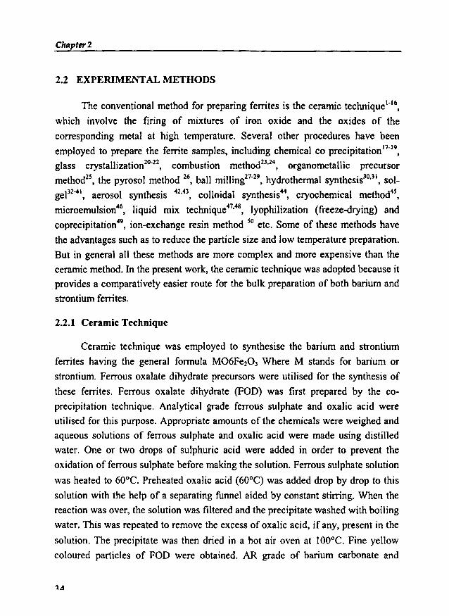
2.2 EXPERIMENTAL METHODS
The conventional method for preparing ferrites is the ceramic technique':",
which involve the firing of mixtures of iron oxide and the oxides of the
corresponding metal at high temperature. Several other procedures have been
employed to prepare the ferrite samples, including chemical eo precipitation":",
glass crystallization20-22, combustion method":", organometallic precursor
method", the pyrosol method 26, ball milling27.29, hydrothermal synthesis30.31, sol
gel32-4I, aerosol synthesis 42,43, colloidal synthesis", cryochemical method",
microernulsion", liquid mix technique47.48, lyophilization (freeze-drying) and
coprecipitation", ion-exchange resin method 50 etc. Some of these methods have
the advantages such as to reduce the particle size and low temperature preparation.
But in general all these methods are more complex and more expensive than the
ceramic method. In the present work, the ceramic technique was adopted because it
provides a comparatively easier route for the bulk preparation of both barium and
strontium ferrites.
2.2.1 Ceramic Technique
Ceramic technique was employed to synthesise the barium and strontium
ferrites having the general formula M06Fe203 Where M stands for barium or
strontium. Ferrous oxalate dihydrate precursors were utilised for the synthesis of
these ferrites. Ferrous oxalate dihydrate (FOD) was first prepared by the eo
precipitation technique. Analytical grade ferrous sulphate and oxalic acid were
utilised for this purpose. Appropriate amounts of the chemicals were weighed and
aqueous solutions of ferrous sulphate and oxalic acid were made using distilled
water. One or two drops of sulphuric acid were added in order to prevent the
oxidation of ferrous sulphate before making the solution. Ferrous sulphate solution
was heated to 60°C. Preheated oxalic acid (60°C) was added drop by drop to this
solution with the help of a separating funnel aided by constant stirring. When the
reaction was over, the solution was filtered and the precipitate washed with boiling
water. This was repeated to remove the excess of oxalic acid, if any, present in the
solution. The precipitate was then dried in a hot air oven at 100°C. Fine yellow
coloured particles of FOD were obtained. AR grade of barium carbonate and
1.11
Experimental Techniques-strontium carbonate were the other precursor materials employed for the
preparation ofbarium ferrite and strontium ferrite.
Pure a-Fe203' prepared by the decomposition of the freshly prepared ferrous
oxalate dihydrate was mixed with appropriate amounts of the AR grade barium
carbonate and strontium carbonate. A slurry was made by using AR grade acetone
in an agate mortar. They were homogenised thoroughly by mixing for a long time
and pre-sintered at 500°C for three hours in a furnace under ambient atmosphere.
The homogenisation and pre-sintering were carried out three time. The pre-sintered
powder sample of the BaF and SrF was then pressed in a hydraulic press into
cylindrical pellets by using a mould of die steel having a diameter of 12 mm. The
fmal sintering of the powder sample and the pellet in the furnace was carried out at
12000C for 24 hours. They were then cooled under ambient conditions and these
powders and pellets were used for further characterisation and studies. The
properties of the final product depend on the sintering temperature, time, cooling
rate and environment.
1.1.2 Structural Evaluation of Barium/Strontium Ferrite by X-Ray
Powder Diffraction
The X-ray powder diffraction technique was used to evaluate the various
structural parameters namely relative intensity 'IJIo', inter atomic spacing 'd', and
lattice parameter 'a'. The identification of the phase was also conducted by using
X-ray diffraction. The powder diffractograms of the samples were recorded by
employing Rigaku 0 Max -C, X-ray powder diffractometer using Cu Ka radiation
of wavelength (A) 1.54098 AO. From the XRD spectrum obtained '1/10', '28' and
'W values corresponding to each peaks were noted and the different parameters
were calculated by using the following relations. Inter atomic spacing was
calculated by utilising the relation SI·53
d= A2sin8
where 'A' is the wavelength of the X-ray radiation used.
(2.1)
(2.2)
Chapter 2
The particle size was calculated from the XRD data by using Schererformula, which is given by
D = 0.9 A.~ cosS
where 'P' is the full width half maximum of the intensity.
Surface area of the ceramic samples can be calculated by using the empirical relation
(2.3)
where 'D' is particle size in nm and 'p' is the density of the sample in g fcm354.
2.2.3 Mixing and processability study of the compounds using BrabenderPlasticorder
Brabender plasticorder has been widely used for measuring processability ofpolymer. This torque rheometer is essentially a device for measuring the torquegenerated due to the resistance of a material to mastication or flow underpreselected conditions of shear and temperature. The heart of the torque rhoemeteris a jacketed mixing chamber whose volume is approximately 40 cc for the model
used (PL 3S). Mixing and shearing of the material in the mixing chamber is done
by horizontal rotors with protrusions. The resistance put up by the test material
against rotating rotors in the mixing chamber is indicated with the help of a
dynamometer balance. The dynamometer is attached to a mechanical measuring
system, which records the torque. A de thyrister controlled drive is used for speed
control of the rotors (0 to 150 rpm). The temperature can be varied up to 300°C. A
thermocouple with a recorder is used for temperature measurements. Different
types of rotors can be employed depending upon the nature of the polymer used.
The rotors can be easily mounted using the simple fastening and coupling system.
The rubber was charged into the mixing chamber after setting the test conditions.
When the nerve of the rubber had disappeared. the compounding ingredients wereadded as per sequence given in ASTM D 3182 (1982). The final torque displayed
on the dial gauge was noted. The compound was discharged after completion of the
mixing. Mixing time and temperature were controlled during the process. Thehomogenisation of the compound was carried out using a two roll mill.
36
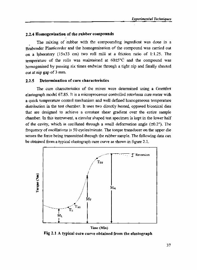
Experimental Techniques
2.2.4 Homogenisation of the rubber compounds
• The mixing of rubber with the compounding ingredient was done in a
Brabender Plasticorder and the homogenisation of the compound was carried out
on a laboratory (l5x33 cm) two roll mill at a friction ratio of I: 1.25. The
temperature of the rolls was maintained at 60±5°C and the compound was
homogenised by passing six times endwise through a tight nip and finally sheeted
out at nip gap of 3 mm.
2.2.5 Determination of cure characteristics
The cure characteristics of the mixes were determined using a Goettfert
elastograph model 67.85. It is a microprocessor controlled rotorlesss cure meter with
a quick temperature control mechanism and well defined homogeneous temperaturedistribution in the test chamber. It uses two directly heated, opposed biconical dies
that are designed to achieve a constant shear gradient over the entire samplechamber. In this instrument, a circular shaped test specimen is kept in the lower half
of the cavity, which is oscillated through a small deformation angle (±O.2°). Thefrequency of oscillations is 50 cycles/minute. The torque transducer on the upper die
senses the force being transmitted through the rubber sample. The following data canbe obtained from a typical e1astograph cure curve as shown in figure 2.1.
.1 Reversion
Time (Min)
Fig 2.1 A typical cure curve obtained from the elastograph
37
Chapter 2
(i) Minimum torque, ML
Torqoe obtained by mix after homogenising at the test temperature and
before the onset of cure.
(ii) Maximum torque, MH
Maximum torque recorded at the completion of cure.
(iii) Torque, MT
Torque at any given time T
(iv) Optimum Cure time, T90
This is the time taken for obtaining 90% of the maximum torque
(v) Scorch time, T IO
It is the time taken for two unit rise (0.02 Nm) above minimum torque (i.e.
about 10% vulcanization).
(vi) Induction time, T,
It is the time taken for one unit rise above minimum torque (i.e. about 5 %
vulcanization).
(vii) Cure rate index
Cure rate index is calculated from the following equation.
Cure rate index = 100 / T90- T 10
Where, T90 and T lo are the times corresponding to the optimum cure and
scorch respectively.
The elastograph microprocessor evaluates the vulcanisation curve and prints
out the data after each measurement.
2.2.6 Moulding of Test Specimens
The test specimens for determining the physical properties are prepared in
standard moulds by compression moulding on an electrically heated press having
45 x 45 cm platens at a pressure of 140 Kg cm-2 on the mould. The rubber
38
Experilnenta I Techniques
compounds are vulcanised up to their respective optimum cure time at 150°C.
Mouldings are cooled quickly in water at the end of the curing cycle and stored in a
cool and dark place for 24 hours and are used for subsequent physical tests. For
samples having thickness more than 6 mm (abrasion resistance, compression set
etc.) additional curing time based on the sample thickness is given to obtain
satisfactory moulding.
2.3 PHYSICAL TEST METHODS
2.3.1 Stress Strain Properties
Tensile properties of the vulcanisate are determined as per ASTM 0 412
(1980) using dumb-be11 specimens on an Instron Universal Testing Machine,
Model 4411 Test System. All tests are carried out at 28±2°C. Dumbbell specimens
for the tests are punched out from the compression moulded sheets along the mill
grain direction using a standard die. The thickness of the narrow portion is
measured by bench thickness gauge. The sample is held between the two grips on
the UTM, the upper grip of which is fixed. The rate of separation of the power
actuated lower grip is fixed at 500 mmlmin. The tensile strength, elongation at
break and modulus at different elongations are recorded and evaluated after each
measurement by the microprocessor.
2.3.2 Abrasion resistance
The abrasion resistance of the samples is determined using a DIN abrader
(DIN 53516). Cylindrical samples of 15 mm diameter and 20 mm length is kept on
a rotating sample holder and 10 N load was applied. Initially a pre run is given for
the sample and its weight taken. The weight after the final run is also noted. The
difference in weight is the weight loss on abrasion. It is expressed as the volume of
the test piece abraded by its travel through 42 m on a standard abrasive surface.
The volume loss on abrasion was calculated as follows:
V ==M1/p
Where V == volume loss, L\M == mass loss, and p == density of the sample.
Abrasion resistance is the reciprocal of volume loss on abrasion.

Chapter 2
2.3.3 Hardness
Hardness IS defined as the resistance of a material to deformation,
particularly permanent deformation, indentation or scratching. Durometer hardness
tester is used for measuring the relative hardness of soft materials. It is based on the
penetration of specified indenter forced into the material under specified
conditions. It consists of a pressure foot, an indenter and a dial gauge. The indenter
is spring loaded and the point of the indenter protrudes through the opening in the
base. There are several instruments used to measure the hardness of soft sponge up
to ebonite type material. The most commonly used are Durometers Type A and
Type D. The basic difference between the two types is the shape and dimension of
the indenter. The hardness numbers derived from either scale are just numbers
without any units. Type A Durometer is used for measuring the hardness of
relatively soft materials and Type D Durometer is used for measuring the hardness
of harder material. The hardness measured using Type A Durometer is expressed in
a unit called 'Shore A' and that measured using Type D is called 'Shore D'. On
shore A scale 0 would be soft and 100 hard S4-S8.
The hardness (Shore A) of the moulded samples were tested by using Zwick
3114 hardness tester in accordance with ASTM D 2240 - 86. The tests were
carried out on a mechanically unstressed sample of 12 mm diameter and minimum
6 mm thickness. The test is conducted by first placing the specimen on a hard, flat
surface and the pressure foot of the instrument is pressed onto the specimen. A load
of 12.5N was applied and after ensuring firm contact with the specimen. the
readings were taken after 10 seconds of indentation.
2.4 ELECTRICAL CHARACTERISATION
2.4.1 Dielectric Constant
The investigation of the dielectric properties helps us in understanding the
nature and structure of the materials. An accurate measurement of these properties
will provide valuable information about the electrical behaviour of the materials
and its usefulness for various applications. This helps to improve the design and
quality of the existing devices. Hence an exact knowledge of the dielectric
Experimental Techniques-properties of a material is a prerequisite for many technological applications.
Information on dielectric properties is also very useful for improving the
microwave absorbing properties of the ferrites. The most important among the
dielectric properties is the dielectric constant or permittivity. The permittivity is
defined as the ratio of the field strength in vacuum to that in the material for same
distribution of charges. Dielectric constant is dependent on parameters like
frequency, temperature, orientation, composition, pressure and molecular structure
of the material. Applications in the microwave processing of food, rubber, plastics
and ceramics would benefit from the knowledge of dielectric properties.
An electrical conductor charged with a quantity of electricity q at a potential
V is said to have a capacity C=qN. The capacity of a simple parallel plate
capacitor is given by
E Ac=d
(2.4)
where A is the area of the parallel plates, d is the separation between the
plates and e is the ratio of dielectric constant of the medium between the plates to
thatof free space.
This equation is exploited in evaluating the dielectric constant of the ceramic
barium and strontium ferrites and rubber ferrite composites containing BaF/SrF in
natural and nitrile rubber.
The dielectric properties of the ceramic samples and the RFCs were studied
using a dielectric cell and an impedance analyser (Model: HP 4285A) in the
fRquency range 100KHz to 8 MHz. A dielectric cell was fabricated for this
purpose. Figure 2.2 shows a schematic diagram of the fabricated dielectric cell.
BaF and SrF samples. prepared by ceramic technique were made in the form
of pelIets having diameter of 12mm diameter. These were then loaded onto the
spring loaded sample holder assembly. The capacitance values at different
frequencies ranging from 100 KHz to 8 MHz were noted. The dielectric constantwas calculated using the formula
c ~ & 0'& r .Ad
(2.5)

Chapter 2
where A is the area of the sample pieces used and d their thickness. £0 and er are the
dielectric constant of air and the sample respectively and C is the capacitance
value.
The dielectric constants were evaluated for RFCs containing different
loadings of the BaF and SrF, both with and without carbon black in NR and NBR
matrix. For this disc shaped samples having diameter 12 mm were punched out
from the rubber sheet. The dielectric cell is provided with provisions for heating
and the measurements were carried out from 303K to 393K for all samples.
Dielectric phenomenon arises from the interactions of the electric field with
different charged species such as electrons, protons, ions and also the electron
shells and nuclei which constitute the dielectric material. In any dielectric material
there will be some power loss because of the work done to overcome the frictional
damping forces encountered by the dipoles during their rotations.
When an ac sinusoidal voltage source is placed across the capacitor, the resulting
current will be made of a charging current and a loss current that is related to the
dielectric permittivity. Here we have considered only in the relative permittivity
(Er) of the material and the loss (tan 0). Permittivity describes the interaction of a
material with an electric field. The relative permittivity is given by Er = El EO' The
complex relative permittivity is given by
o EO El - jellEr = - = -----''---
Eo Eo(2.6)
Where 'Eo' is the permittivity of free space, which is 8.854 x 10⁻¹² Flm in SI
units. The real part of dielectric permittivity (El) is a measure of how much energy
from an external electric field is stored in a material. The imaginary part of the
dielectric permittivity (Er " ) is called the loss factor. It is a measure of the energy
dissipation or heat generation in the material when an external electric field is
applied. The loss current will be always in phase with the applied voltage. But the
charging current will be always out of phase and in ideal case the phase change
will be 90°. If loss current 'IL ' and charging current 'le' makes angles 'a' and '0'
respectively with the total current 'h' passing through the capacitor, the dielectric
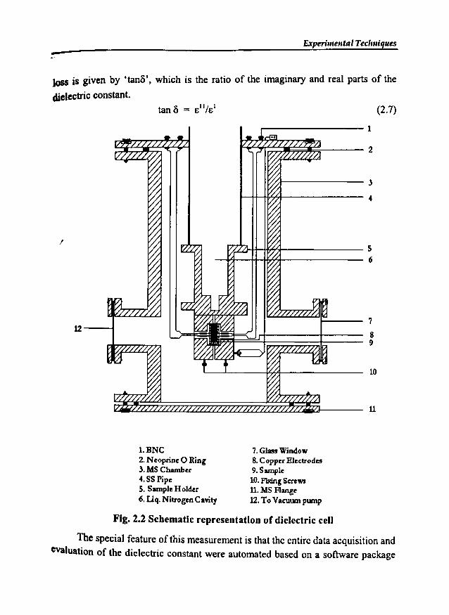
Experimental Tecl",iques-losS is given by 'tand', which is the ratio of the imaginary and real parts of the
dielectric constant.(2.7)
I
12---1
.-----------1
;+-------- 3
t-t+--t¥:nt--------4
'LL.'1-+l-+fh<:>!-------s--w--+t-~nt_-------6
7
89
10
u
1.HNC2. Neopnne 0 Ring3.MSChamber4.55 Pipe5. Sunph: Holder6. Liq. Nitrogen Cavity
7. Glass Window8.Copper Electrodes9. Sunple
10. Fbdnl Screws11. MSFlange12. To Vacuum pump
Fig. 2.2 Schematic representation of dielectric cell
The special feature of this measurement is that the entire data acquisition andevaluation of the dielectric constant were automated based on a software package
Chapter 2
developed and modified by us. This was done with the help of a base packagesupplied by National Instruments called 'LabVIEW', which in turn is based on G
Programming. LabVIEW is a programming language for data acquisition, analysis,simulation or computer control of instruments, techniques or processes. LabVIEW
is an acronym for Laboratory Virtual Instrument Engineering Workbench and is anobject oriented language and its style, syntax and data flow is different fromconventional linear programming languages. Appropriate modifications wereincorporated in the software so as to enable the data acquisition automatic and
visual observation of the graphs on the computer screen. The characteristic feature
of this automatic data acquisition is that it has been possible to acquire 20,000 datapoints or more in a matter of 5 to 10 minutes. By using the modified package the
data can be plotted and analysed.
2.4.2 AC conductivity measurements
The ac electrical conductivity of both the ceramic and rubber ferritecomposites was evaluated by calculating the ac conductivity values using dielectricparameters. The dielectric studies of both ceramic and rubber ferrite compositeswere carried out using a dielectric cell and an impedance analyzer (Model: HP4285A). Disc shaped samples were used to find out the dielectric constant. Thecapacitance and dielectric loss in the frequency range 100KHz - 8MHz were found
out. Dielectric constant or relative permittivity was calculated using the formula
C.dE =- (2.8)
r Eo.A
where d is the thickness of the sample, C the capacitance and A the area of cross
section of the sample. Er is the relative permittivity of the material which is a
dimensionless quantity. The ac conductivity of these samples were then evaluatedusing the relation
<Jac = 2nf tand Eo Er (2.9 )
where f is the frequency of the applied field and tan8 is the loss factor. The
principle and the theory underlying the evaluation of <Jac from dielectricmeasurements are based on a treatment dealt by Goswamy 64. The measured values
of Er and tanf from the dielectric measurements for both ceramic and RFCs wereused for the calculation of the ae conductivity.

Experimental Techniques
2.5 MAGNETIC CHARACTERIZATION
The magnetic characterization of both the ceramic BaF/SrF and rubber
ferrite composites (RFC) were carried out using a Vibrating Sample
Magnetometer.
2.5.1 Vibrating Sample Magnetometry
Instrument used for the magnetic measurements is a Vibrating Sample
Magnetometer (VSM), model: 4500 (EG&G PARC). A simplified block diagram is
given in figure 2.3 and the VSM set up used for the study is given in figure 2.4.
Magnetic properties of the rubber ferrite composites for different loadings of the
magnetic filler with and without carbon black were carried out. Parameters like
Saturation magnetisation (Mj), Magnetic remanence or Retentivity (M,) and
Coercivity (He) were evaluated from the hysteresis loops obtained at room
temperature.
Programming IMagnometerFunction Model 4500Generator
BipolarMagnet
~ ~Power Supply
Model 4500Phase SensitiveElectronics
L...------l Hall ProbeGaussmeter
Fig. 2.3 Block diagram of VSM setup
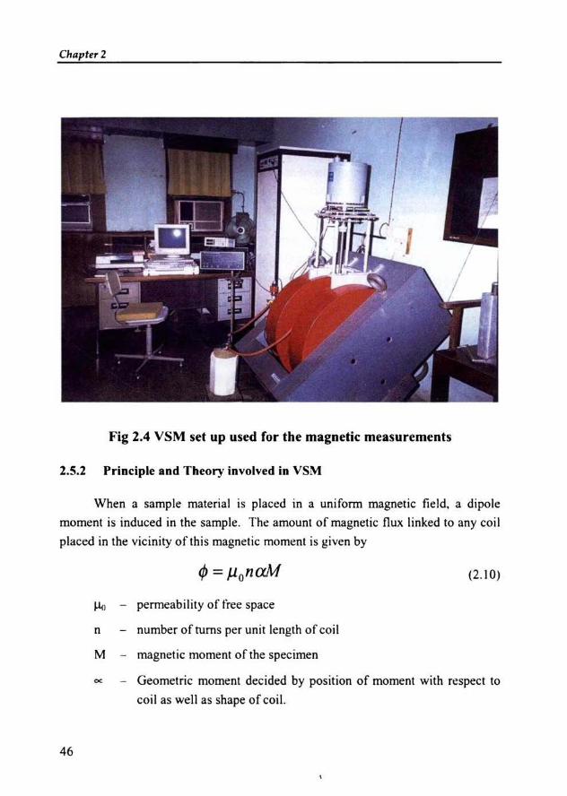
Chaptrr 2
Fig 2.4 VSM set up used for the magnetic measurements
2.5.2 Principle and T heory involved in VSM
When a sample materia l is placed in a uniform magnetic field, a dipole
moment is induced in the sample. The amount of magnetic flux linked to any coi l
placed in the vicinity of this magnetic moment is given by
(2.10)
~ - permeability of free space
n - number ofrums per unit length of coil
M - magnetic moment of the specimen
cc _ Geomet ric moment decided by position of moment with respect to
coil as well as shape of coil.
46
Anhannonic oscillator of the type Z = Zo + A exp(jo.>t)
Experimental Techniques
(2.11)
induces an emf in the stationary detection coil. The induced emf is given by
d4». aa joltV = --= - Jo.>J.lonMA(-)e
dt Oz(2.12)
If amplitude of vibration (A), frequency and Ba are constant over theOz
sample zone then induced voltage is proportional to the magnetic moment of the
sample. This is the basic idea behind VSM 59-63.
When the magnetic material is placed in a uniform magnetic field, a dipole
moment is induced which is proportional to the susceptibility of the sample and the
applied field. If the sample is made to undergo sinusoidal motion, an electrical
signal can as well be induced in suitably located stationary pick up coils. This
signal, which is at the vibration frequency, is proportional to the magnetic moment
and vibration amplitude. This means of producing an electrical signal related to the
magnetic properties of a sample material is the basic principle used in the design of
a VSM to measure the magnetic properties.
In model PARC 4500 VSM the material under study is contained in a sample
holder, which is centered in the region between the poles of a laboratory
electromagnet. A slender vertical sample rod connects the sample holder with a
transducer assembly located above the magnet. The transducer converts a sinusoidal
ac drive signal in to a sinusoidal vertical vibration of the sample rod and the sample
is thus made to undergo a sinusoidal motion in a uniform magnetic field. Coils
mounted on the poles of the magnet pick up the signal resulting from the sample
motion. This ac signal at the vibrating frequency is proportional to the magnitude of
the moment induced in the sample. However it is also proportional to the vibration
amplitude and frequency. A servo system maintains constancy in the drive amplitude
and frequency so that the output accurately tracks the moment level without
degradation due to variation in the amplitude and frequency of vibration.
The servo technique uses a vibrating capacitor located beneath the
transducer to generate an ac control signal that varies solely with the vibration
47
Chapter 2
amplitude and frequency. The signal, which is at the vibration frequency, is fed
back to the oscillator where it is compared with the drive signal so as to maintain
constant drive output. It is also phase adjusted and routed to the signal demodulator
where it functions as the reference drive signal. The signal originating from the
sample in the pick up coils is then buffered, amplified and applied to the
demodulator. There it is synchronously demodulated with respect to the reference
signal derived from the moving capacitor assembly. The resulting de output is an
analog signal, which depends only on the magnitude of the magnetic moment, and
not influenced by the amplitude and frequency drifts.
The system is provided with facilities for low temperature measurements as
well for the thennomagnetisation measurements. That is, the variation of saturation
magnetisation with temperature can be studied by using this system.
Experimental Teclmique«-IlEFERENCES
1 B.V. Bluse, M.B. Dangare, S.A.Patil,SRSawant, 1. Mater. Sci. Lett. 10 (1991) 922.
2 Sawadh. P. S, and Kulkami. D.K, Materials Chemistry and physics. 63 (2000)
170-173.
3 Ahmed. M.A, Phys. Stat. Sol. A 111 (1989) 567.
4 Valenzuela R, 'Magnetic Ceramics'; Cambridge, Cambridge University
Press, 1994.
, Swallow. D, and Jordan. A. K, 'The fabrication of ferrites', Proc. Br. Ceram.
Soc.,2 (1964) 1-17.
6 Stuijts. A. L, 'Microstructural considerations in ferromagnetic ceramics', Proc.
3n1 Int. Mater. Symp. on Ceramic Microstructures, Univ. Calif. Berkeley, (1966).
7 Heck. C, and Weber. J, 'How firing atmospheres influence ferrite properties',
Ceramic Ind., (1961), 77, part 1,5, 75; part 2, 6, 66.
8 Jackson. H, 'Kilns for the manufacture of ferrites', Proc. Br. Ceram. Soc., 2,
(1964) 43-53.
9 Stijntjes, T. G. W, Presented at ICF4, Advances in Ceramics 16 (1985) 493.
10 Haneda. K, and Kojima. H, J. Amer. Ceram. Soc. 57, (1974) 68.
11 Benito. G, M.P. Morales, J. Reequena, V.Raposo, M.Vazquez, and 1.S. Moya,
J. Magn. Magn. Mater., 234 (2001) 65-72.
12 Sung-Soo Kim and Dae-Hee Han, IEEE Trans.Magn., 30,6 (1994).
13 Daniels. J.M and Rosencwaig, Can.J.Phys. 48 (1970) 381.
14 Leung. L.K, Evans. BJ, and Morrish. A.H, phys. Rev. B 8 (1973) 29.
IS PatH. A.N, Pati)o M.G. Patankar. K.K, Mathe. V.L, Mahajan. R.P and Pati)o S.A,
Bull. Mater. Sci., 23, 5 (2000) 447-452.
16 Murthy. S.R, Bull. Mater. Sci., 24,4 (2001) 379-383.
17 Haneda. K, Miyakana. C, and Kojima. C, J. Amer. Ceram. Soc. 57 (1974) 354.
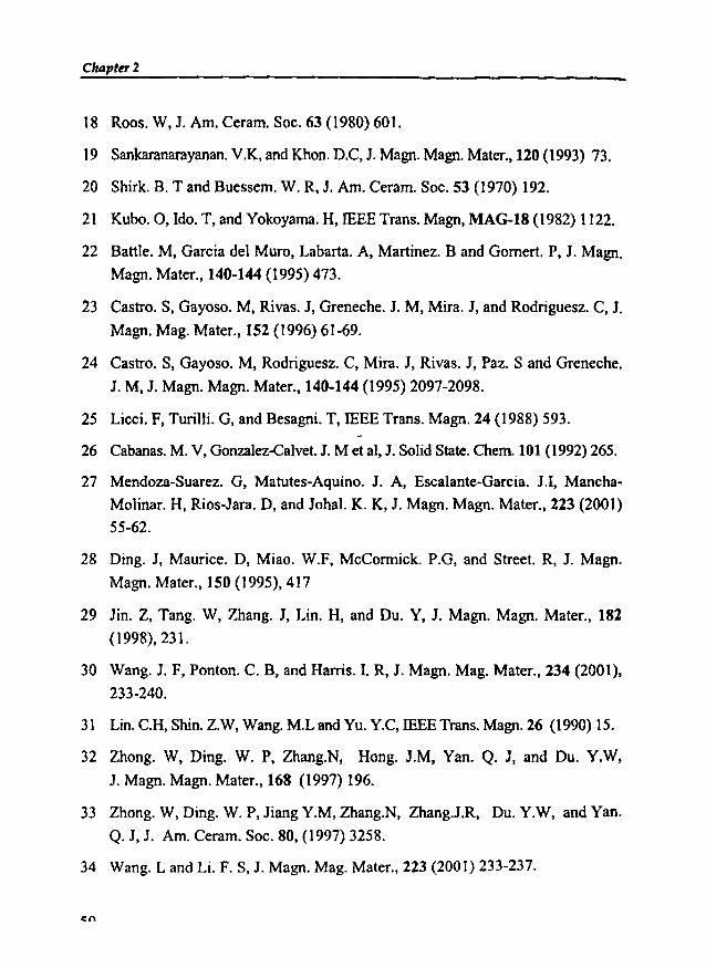
Chapter 2
18 Roos. W, J. Am. Ceram. Soc. 63 (1980) 601.
19 Sankaranarayanan. V.K, and Khon. D.C, J. Magn. Magn. Mater., 120 (1993) 73.
20 Shirk. B. T and Buessem. W. R, 1. Am. Ceram. Soc. 53 (1970) 192.
21 Kubo. 0, Ido. T, and Yokoyama. H, IEEE Trans. Magn, MAG-18 (1982) 1122.
22 Battle. M, Garcia del Muro, Labarta. A, Martinez. Band Gomert. P, J. Magn.
Magn. Mater., 140-144 (1995) 473.
23 Castro. S, Gayoso. M, Rivas. J, Greneche. J. M, Mira. J, and Rodriguesz. C, J.Magn. Mag. Mater., 152 (1996) 61-69.
24 Castro. S, Gayoso. M, Rodriguesz. C, Mira. J, Rivas, J, Paz. Sand Greneche.
1. M, 1. Magn. Magn. Mater., 140·144 (1995) 2097-2098.
25 Licci. F, Turilli. G, and Besagni. T, IEEE Trans. Magn. 24 (1988) 593.
26 Cabanas. M. V, Gonzalez-Calvet. 1. M et aI, J. Solid State. Chem. 101 (1992) 265.
27 Mendoza-Suarez, G, Matutes-Aquino. J. A, Escalante-Garcia. J.I, Mancha
Molinar. H, Rios-Jara, D, and Johal. K. K, J. Magn. Magn. Mater., 223 (2001)
55-62.
28 Ding. J, Maurice. D, Miao. W.F, McCorrnick. P.G, and Street. R, J. Magn.
Magn. Mater., 150 (1995),417
29 Jin. Z, Tang. W, Zhang. J, Lin. H, and Du. Y, 1. Magn. Magn. Mater., 182
(1998), 231.
30 Wang. J. F, Ponton. C. B, and Hams.!. R, J. Magn. Mag. Mater., 234 (2001),
233-240.
31 Lin. C.H, Shin. Z.W, Wang. M.L and Vu. YC, IEEE Trans. Magn. 26 (1990) 15.
32 Zhong. W, Ding. W. P, Zhang.N, Hong. J.M, Van. Q. J, and Du. Y.W,
1. Magn. Magn. Mater., 168 (1997) 196.
33 Zhong. W, Ding. W. P, Jiang Y.M, Zhang.N, Zhang.J.R, Du. Y.W, and Yan.
Q. J, J. Am. Ceram. Soc. 80, (1997) 3258.
34 Wang. Land Li. F. S, J. Magn. Mag. Mater., 223 (2001) 233-237.
cn
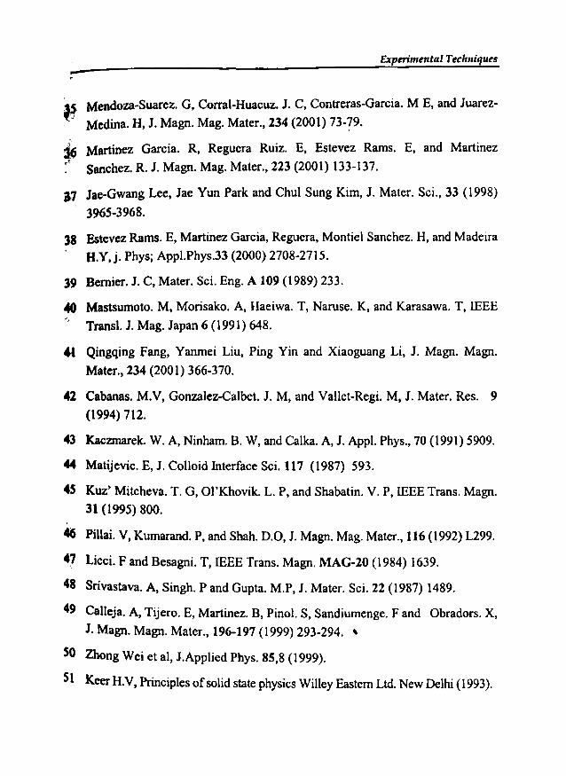
Experimental Techniques-.,~ Mendoza~Suarez. G, Corral-Huacuz. J. C, Contreras-Garcia. M E, and Juarez-
Medina. H, J. Magn. Mag. Mater., 234 (2001) 73-79.
~ Martinez Garcia. R, Reguera Ruiz. E, Estevez Rams. E, and Martinez
<' Sanchez. R. J. Magn. Mag, Mater., 223 (2001) 133-137.
17 Jae-Gwang Lee, Jae Yun Park and Chul Sung Kim, J. Mater. Sci., 33 (1998)
396S~3968.
38 Estevez Rams. E, Martinez Garcia, Reguera, Montie1 Sanchez. H, and Madeira
H.Y,j. Phys; Appl.Phys.33 (2000) 2708-2715.
39 Bernier. J. C, Mater. Sci. Eng. A 109 (1989) 233.
40 Mastsumoto. M, Morisako. A, Haeiwa. T, Naruse. K, and Karasawa. T,IEEE
Transl. J. Mag. Japan 6 (1991) 648.
~t Qingqing Fang, Yanmei Liu, Ping Yin and Xiaoguang Li, J. Magn. Magn.
Mater., 234 (2001) 366-370.
42 Cabanas. M.V, Gonzalez-Calbet, J. M, and Vallet-Regi. M, J. Mater. Res. 9
(1994) 712.
43 Kaczmarek, W. A, Ninham, B. W, and Calka. A, J. Appl. Phys., 70 (1991) 5909.
44 Matijevic. E, J. Colloid Interface Sci. 117 (1987) 593.
45 Kuz' Mitcheva. T. G, OI'Khovik. L. P, and Shabatin. V. P, IEEE Trans. Magn.
31 (1995) 800.
46 Pillai. V, Kumarand. P, and Shah. 0.0, J. Magn. Mag. Mater., 116 (1992) L299.
47 Licci. F and Besagni. T, IEEE Trans. Magn. MAG-20 (1984) 1639.
48 Srivastava. A, Singh. P and Gupta. M.P, J. Mater. Sci, 22 (1987) 1489.
49 CalIeja. A, Tijero. E, Martinez. B, Pinol. S, Sandiumenge. F and Obradors. X,
J. Magn. Magn. Mater., 196-197 (1999) 293-294. ~
SO Zhong Wei et al, J.Applied Phys. 85,8 (1999).
SI Keer H.V, Principles ofsolid state physics Willey Eastern Ltd. New Delhi (1993).

Chapter 2
52 Cullity. B.D, 'Elements of X-ray diffraction', (Philippines, Addison-Wesley
Publishing Company, Inc.) 2ndEdn. (1978).
53 Charles Kittel, Introduction to Solid State Physics, 1997, John WHey and Sons,
New York.
54 Blow C.M. and C. Hepburn, 'Rubber Technology and Manufacture', 2nd
edition, (1985), Butterworths Publishers, London.
55 Vishu Shah, handbook of plastic testing technology, John Wiley and Sons Inc,
USA 1998.
56 AlIen W, Natural Rubber and the Synthetics, 1972, Granada Publishing Ltd.
57 Steven Blow. Hand book of Rubber Technology, 1998, Galgotia Publishing
Pvt. Ltd.
58 Charles A Harper, Handbook of Plastic, Elastomers and Composites, 2nd
edition, McGraw Hill Inc.1992.
59 Brailsford. F, Physical principles ofmagnetism, 1966, D Van Nostrand Co. Ltd.
60 Haberey. F and H.J.P. Wijn, Phys. Stat. Sol. (a) 26 (1968) 231.
61 Krishnan R.V. and A. Banerjee, Rev. Sci. Instrum., 70, I (1999) 85.
62 Simon Foner, Rev. Sci. Instrum. 30, 7 (1959) 548-557.
63 Joseph A. Pesch, Rev. Sci. Instrum, 54,4 (1983) 480.
64 Goswami A, Thin Film Fundamentals, (1996) New age international
Publishers Ltd., New Delhi.
52

~hapter3-
PREPARATION AND CHARACTERISATIONOF RUBBER FERRITE COMPOSITES
This chapter deals with the preparation and characterisation of barium and
atrontium ferrite and its incorporation into the rubber matrixes to prepare rubber
ferrite composites (RFC). The details of the characterisations carried out by
employing various analytical tools at appropriate stages are depicted in the form of
• flowchart as shown in figure 3.1.
ac conductivity Tensile & Hardness
Fig 3.1 Flow chart for the preparation and characterisation of RFC
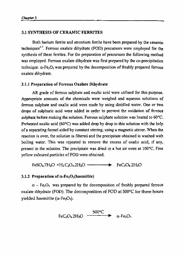
Chllpter3
3.1 SYNTHESIS OF CERAMIC FERRITES
Both barium ferrite and strontium ferrite have been prepared by the ceramic
techniques'", Ferrous oxalate dihydrate (FOD) precursors were employed for the
synthesis of these ferrites. For the preparation of precursors the following method
was employed. Ferrous oxalate dihydrate was first prepared by the eo-precipitation
technique. a-Fe203 was prepared by the decomposition of freshly prepared ferrous
oxalate dihydrate.
3.1.1 Preparation of Ferrous Oxalate Dihydrate
AR grade of ferrous sulphate and oxalic acid were utilised for this purpose.
Appropriate amounts of the chemicals were weighed and aqueous solutions of
ferrous sulphate and oxalic acid were made by using distilled water. One or two
drops of sulphuric acid were added in order to prevent the oxidation of ferrous
sulphate before making the solution. Ferrous sulphate solution was heated to 60°C.
Preheated oxalic acid (60°C) was added drop by drop to this solution with the help
of a separating funnel aided by constant stirring, using a magnetic stirrer. When the
reaction is over, the solution is filtered and the precipitate obtained is washed with
boiling water. This was repeated to remove the excess of oxalic acid, if any,
present in the solution. The precipitate was dried in a hot air oven at 100°C. Fine
yellow coloured particles ofFOD were obtained.
3.1.2 Preparation of a-FezOJ(haemitite)
a - Fe203 was prepared by the decomposition of freshly prepared ferrous
oxalate dihydrate (FOD). The decomposition of FOD at 500°C for three hours
yielded haemitite (a-Fe20 3).

Preparation andCharacterisation of RFCs
;J.l.3 Preparation of Barium and Strontium Ferrites
Appropriate amounts of the AR grade barium carbonate and strontium
carbonate and a-Fe203 were taken and a slurry was made using AR grade acetone.
This mixture was thoroughly mixed using an agate mortar. The mixing was
oontinued for one hour to produce a homogeneous mixture of fine particles. After
drying, this homogeneous mixture was pre-sintered at around 500°C for six hours
iD a muffle furnace. The pre-fired samples were again mixed to ensure
homogeneity and again pre-fired at the same temperature. The pre-sintered powder
IlU'Ilple of the BaF and SrF were then pressed in a hydraulic press into cylindrical
peIlets by using a mould of die steel having a diameter of 12 nun. Final sintering of
the pre-sintered powder sample and the pellet were done at 1200°C by keeping it
inside the furnace for 24 hours. They were then cooled under ambient conditions.
.The final sintered samples were again grinded in an agate mortar for one hour to
ensure homogeneity. These finely ground powder and pellets were used for the
characterisation and for the preparation of RFCs. The properties of the final
product depend on the sintering temperature, time, cooling rate and environment.
BaC03+ 6 Fe203
srC03 + 6 FeZ03
3.1 STRUCTURAL EVALUATION
-----.~ BaFel2 0 19 + CO2
-----.~ SrFel2019 + CO2
The barium ferrite and strontium ferrite powder prepared by the ceramic
technique were analysed by x-ray powder diffraction (XRD) technique using X-ray
difftactometer (Rigaku Dmax-C) with Cu K, (A. = 1.5405 A0).The details are cited in
chapter 2. From the X ray powder diffractograms recorded for BaF and SrF,
parameters namely, inter atomic spacing (d), relative intensity (IJIQ x 100), and
particle size (D) were determined. The evaluation of the structural parameters
indicated that the compounds were monophasic without any detectable impurities
and were crystalline in nature. The XRD spectra of these ferrites are shown in figures3.2 and 3.3.

Chapter 3
1500,..--------------------------,
656055so4035302520oL-_J..-_.1....-._..L-_....L....._-J-_...l-_--..L.._---...J..._~-~
15
29
Fig 3.2 XRD spectrum of barium ferrite
6560555045
2940353025
O\.-_~__.l_.._ __L__...l..__ __L__...L__ __L__...L__ ___I._ __.J
20 70
1600,.--------------------------.
Fig 3.3 XRD spectrum of strontium ferrite
The interatomic spacing and their relative intensities matched well with that of
the reported values in the literatures'". The XRD data are given in tables 3.1 and 3.2.
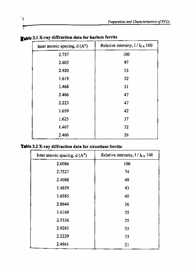
Preparation and Characterisation of RFCs
Inter atomic spacing, d (A0) Relative intensity, l/ 10 x 100
2.757 100
2.605 97
2.920 55
1.619 52
1.468 51
2.406 47
2.223 47
1.659 42
1.625 37
1.467 32
2.460 29
fl)ble 3.1 X-ray diffraction data for barium ferrite
Table 3.2 X-ray diffraction data for strontium ferrite
Inter atomic spacing, d (A0) Relative intensity, I / Io x 100
2.6086 100
2.7527 74
2.4088 49
1.4659 43
1.6585 40
2.8644 36
1.6169 35
2.5336 35
2.9285 33
2.2229 33
2.4961 31

Chaptn' 3
The particle size of the prepared ceramic sample depends very much on the
preparation methods and sintering conditions. Since the particle size and surface
area are inversely proportional, the increase in particle size, naturally decrease the
surface area and vice-versa. The average particle size was calculated from the
x-ray spectra using the Debye Scherrer formula (eqn.2.2) The average particle size
of BaF lie in the range 60-70 nm and had a surface area of 20-25 m2/g, whereas
that of SrF is in the range 25-35 nm with the surface area of around 50 m2/g.
However, it is to be noted here that the particle size 'D' determined by the
Debye Scherrer formula represents only the average distribution of the particles and
hence the surface area calculated by the formula s = 6000 m2/g is only indicative,Dp
unlike that obtained from technique like BET (Branauer, Emmett and Teller).
3.3 INCORPORATION OF FILLERS IN RUBBER MATRIX.
The barium and strontium ferrites thus prepared and characterised were then
incorporated in natural rubber and nitrile rubber matrix according to the recipe
cited in table 3.3 and 3.4 respectively. Compounds were prepared for various
loadings of BaF and SrF, ranging from 40 to 120 phr in steps of20.
Table 3.3 Recipe used for compounding of natural rubber with barium andstrontium ferrite
IngredientsWeight in grams
AO BO CO DO EO FO
Natural rubber 100.0 100.0 100.0 100.0 100.0 100.0
Zinc oxide 5.0 5.0 5.0 5.0 5.0 5.0
Stearic acid 1.5 1.5 1.5 1.5 1.5 1.5
Sulphur 2.5 2.5 2.5 2.5 2.5 2.5
CBS 0.8 0.8 0.8 0.8 0.8 0.8
Antioxidant (SP) 1.0 1.0 1.0 1.0 1.0 1.0
BaF/SrF 0 40 60 80 100 120
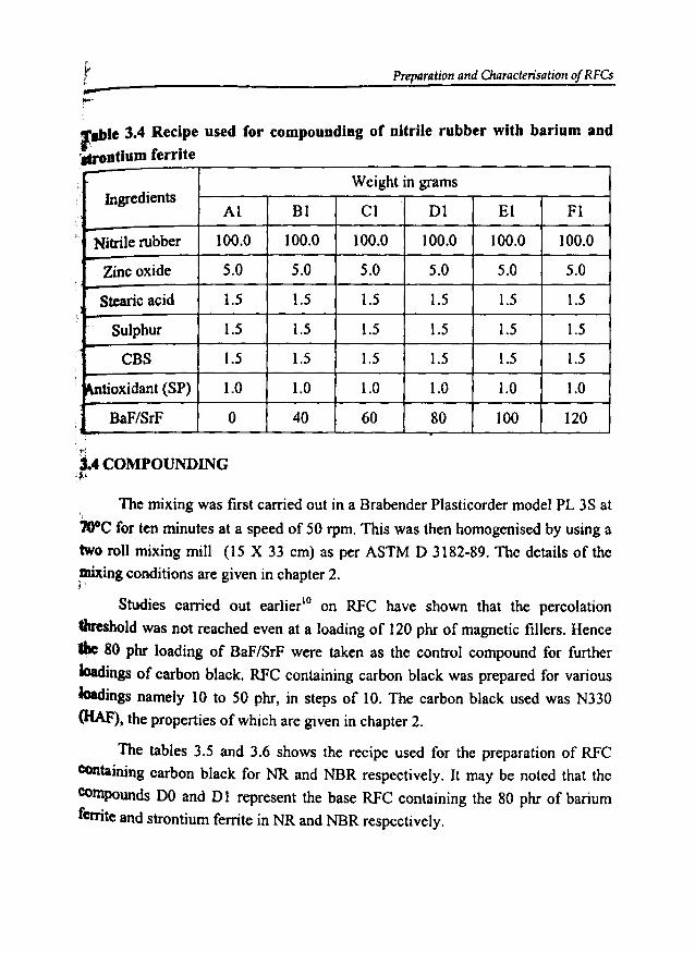
Preparation and Characterisation of RFCs-....,_le 3.4 Recipe used for compounding of nitrile rubber with barium and
·strontium ferrite
Weight in gramsf Ingredients
Al B1 Cl D1 El Fl,
Nitrilerubber 100.0 100.0 100.0 100.0 100.0 100.0
Zinc oxide 5.0 5.0 5.0 5.0 5.0 5.0
Stearic acid 1.5 1.5 1.5 1.5 1.5 1.5
Sulphur 1.5 1.5 1.5 1.5 1.5 1.5
CBS 1.5 1.5 1.5 1.5 1.5 1.5
~tioxidant (SP) 1.0 1.0 1.0 1.0 1.0 1.0
BaF/SrF 0 40 60 80 100 120
't'~
.3.4 COMPOUNDINGf··
The mixing was first carried out in a Brabender Plasticorder model PL 3S at
700C for ten minutes at a speed of 50 rpm. This was then homogenised by using a
two roll mixing mill (15 X 33 cm) as per ASTM D 3182-89. The details of the
,mixing conditions are given in chapter 2., '
Studies carried out earlier'? on RFC have shown that the percolation
threshold was not reached even at a loading of 120 phr of magnetic fillers. Hence
Ibc 80 phr loading of BaF/SrF were taken as the control compound for further
Joadings of carbon black. RFC containing carbon black was prepared for various
Ioadings namely 10 to 50 phr, in steps of 10. The carbon black used was N330
(HAF), the properties of which are given in chapter 2.
The tables 3.5 and 3.6 shows the recipe used for the preparation of RFC
containing carbon black for NR and NBR respectively. It may be noted that the
compounds DO and 01 represent the base RFC containing the 80 phr of barium
ferrite and strontium ferrite in NR and NBR respectively.
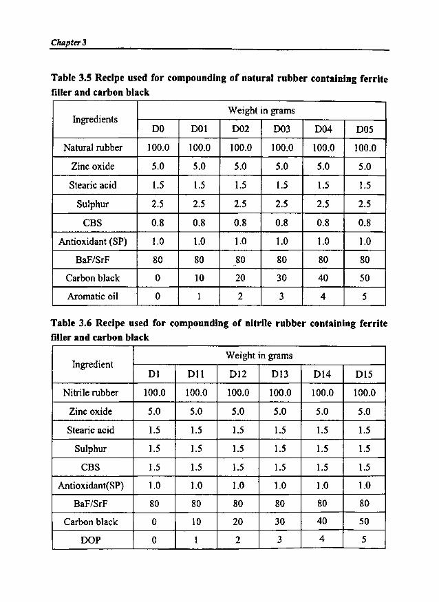
Chapt~3
Table 3.5 Recipe used for compounding of natural rubber containing ferritefiller and carbon black
IngredientsWeight in grams
DO DOl D02 D03 D04 DOS
Natural rubber 100.0 100.0 100.0 100.0 100.0 100.0
Zinc oxide 5.0 5.0 5.0 5.0 5.0 5.0
Stearic acid 1.5 1.5 1.5 1.5 1.5 1.5
Sulphur 2.5 2.5 2.5 2.5 2.5 2.5
CBS 0.8 0.8 0.8 0.8 0.8 0.8
Antioxidant (SP) 1.0 1.0 1.0 1.0 1.0 1.0
BaF/SrF 80 80 80 80 80 80
Carbon black 0 10 20 30 40 50
Aromatic oil 0 1 2 3 4 5
Table 3.6 Recipe used for compounding of nitrile rubber containing ferritefiller and carbon black
IngredientWeight in grams
Dl Dll D12 D13 D14 D15
Nitrile rubber 100.0 100.0 100.0 100.0 100.0 100.0
Zinc oxide 5.0 5.0 5.0 5.0 5.0 5.0
Stearic acid 1.5 1.5 1.5 1.5 1.5 1.5
Sulphur 1.5 1.5 1.5 1.5 1.5 1.5
CBS 1.5 1.5 1.5 1.5 1.5 1.5
Antioxidant(SP) 1.0 1.0 1.0 1.0 1.0 1.0
BaF/SrF 80 80 80 80 80 80
Carbon black 0 10 20 30 40 50
DOP 0 1 2 3 4 5
Preparation and Characterisation of RFCs
3.5 DETERMINATION OF CURE CHARACTERISTICS OF RUBBER
FERRITE COMPOSITES
After the mixing and homogenisation, the compound was matured for a
period of 24 hours. Cure characteristics of the rubber compounds were estimated
using Goettfert elastograph model 67.85. The cure characteristics namely scorch
time, optimum cure time, cure rate index, minimum torque and maximum torque
were determined from the cure graph. The details of the measurement and the
results/discussion are cited in chapter 2 and 4 respectively.
3.6 PREPARATION OF TEST SPECIMENS
The cure time required for each RFC samples was determined from the
respective cure curves. The compounds were then vulcanised at 150°C on an
electrically heated laboratory hydraulic press up to their respective cure times to
make sheets of the sample. The entire test was carried out according to the ASTM
standards. The details are described in chapter 2.
3.7 CONCLUSION
Hexagonal hard ferrites namely barium ferrite and strontium ferrites were
prepared by the ceramic techniques. They were then characterised by using the X
Ray Diffraction technique. Rubber ferrite composites (RFCs) containing various
loadings ofBaF and SrF were synthesised by the incorporation of these ferrites into
both natural rubber and nitrile rubber matrix. The carbon black filled RFCs were
prepared by incorporating varying amount of carbon black into RFC containing an
optimum quantity of ferrite. This method of preparation can be adopted for the
synthesis ofRFCs intended for microwave applications.
Chapter 3
REFERENCES
1. Benito. G, Morales. M. P, Requena. J. Raposo. V, Vazquez. M, and Moya. J.S,
J. Magn. Mag. Mater., 234 (2001),65-72.
2. H.P. Steier, J.Requena, J.S.Moya, J. Mater. Res. 14 (1999) 3647.
3. Shintaro Hayashi, Proceedings of the Intemational Conference, Japan,(1970)
542-544.
4. H. Taguchi, Recent improvements of ferrite magnets, J. Phys. N France, 7
CI-299, (1997).
5. Sung-Soo Kim and Dae-HeeHan,IEEETrans.on Magn.,30, 6 (1994)4554-4556.
6. D.C. Khan, M. Misra, Bull. Mater. Sci. 7 (1985) 253.
7. K. Ishino, Y. Narumiya, Cerm. Bull. .66(1987) 1469.
8. Joint Committeeon Powder Diffractionand Standards - ICDDC. 39-1433, 1990.
9. Joint Committeeon Powder Diffractionand Standards - ICDD C. 33-1340, 1990.
10. K.A. Malini, E.M. Mohammed, S. Sindhu, P.A. Joy, S.K Date, S.D. Kulkami,
P. Kurian, and M.R. Anantharaman, J. Magn. Sci., 36 (2001) 5551-5557.

Chapter 4
CURE CHARACTERISTICS AND MECHANICALPROPERTIES OF
RUBBER FERRITE COMPOSITES
4.1 INTRODUCTION
Rubber ferrite composites, as mentioned earlier are composite materials with
ferrite fillers as one of the constituents and natural or synthetic rubber as the base
mamx'". In these composites both the magnetic filler and the polymer matrix chosen
affect the processability and other physical properties ofthe final product. In tailoring
composites for various applications it is necessary to select the proper filler and
polymer matrix. The physical and chemical properties of the magnetic composites
will possibly be influenced by the interactions with the filler and the matrix.
The knowledge of cure characteristics throws light on the processability of the
composites. Information regarding particle size and surface area of the filler are also
valuable tools in explaining the surface activity with respect to the components present
in the polymer matrix. The processability and other physical properties of the final
product depend not only on the filler properties but also on factors like percolation limit
or nature of the matrix, like saturation! unsaturation I polarity of the rubber.
It is important to study the processability of the polymers since the final
vulcanised product is to be prepared by moulding. Thus it is necessary to evaluate
the cure parameters. The cure parameters namely the maximum torque, minimum
torque, scorch time and cure time were evaluated. The variation in the cure
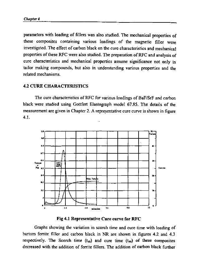
Chapter 4
parameters with loading of fillers was also studied. The mechanical properties of
these composites containing various loadings of the magnetic filler were
investigated. The effect of carbon black on the cure characteristics and mechanical
properties of these RFC were also studied. The preparation of RFC and analysis of
cure characteristics and mechanical properties assume significance not only in
tailor making compounds, but also in understanding various properties and the
related mechanisms.
4.2 CURE CHARACTERISTICS
The cure characteristics of RFC for various loadings of BaF/SrF and carbon
black were studied using Gottfert Elastograph model 67.85. The details of the
measurement are given in Chapter 2. A representative cure curve is shown in figure
4.1.
JO
10
10
114.1 minus" U1.4
tot
1
Il
c....
::~
~... T""l'
t\I 1/ \I" ILJ "r--
oo
cu
o.
1.1
..
Fig 4.1 Representative Cure curve for RFC
Graphs showing the variation in scorch time and cure time with loading of
barium ferrite filler and carbon black in NR are shown in figures 4.2 and 4.3
respectively. The Scorch time (tlO) and cure time (~) of these composites
decreased with the addition of ferrite fillers. The addition of carbon black further

Cure characteristics andmechanical properties of RFCs-reduced both the scorch time and cure time. The scorch time decreased with the
filler loading because the heat of mixing increased as the filler loading increased.
The optimum cure time also decreased with the addition of fillers. The addition of
carbon black further decreased the time of cure.
Load;n, of ca,bon black(ph')
60so)02010oS+-_----.JL-_---l..__-L__..L-_~I..__ _l
10 ,00 110 lOO
Loadin. of Baf (pi,,)
Fig 4.2 Variation in scorch time with loading of barium
ferrite filler and carbon black in NR
loadi •• of cllbon black(ph,)
60so.0)02010o9+-_----.J__---l..__-L__....L...-__.l....-_---j
....... Bar-+- With carbon black
20 60 10 100 120 .40
loadi., of Bar (piu)
Fig 4.3 Variation in cure time with loading of barium
ferrite filler and carbon black in NR

Chapter 4
Similar behaviour was observed with the strontium ferrite filler, with and
without carbon black in NR (Fig 4.4 and 4.5).
Loadin& of carbon black (phr)
60501010o
5 L----L----'-----<'---;:::======~
I1.~ )...1
20 60 so 100 120 140
UliIdinSofSr1' (phr)
Fig 4.4 Variation in scorch time with loading of strontium
ferrite filler and carbon black in NR
Loadins of carbon black (phr)
II 7;;
1.li 6...~ 5
10 20 lO so
--- SrI'__ withCorbon Black
140110100so604020
J~----,----r--~---r---r---r--~
o
LolldinSof SrI' (phr)
Fig 4.5 Variation in cure time with loading of strontium
ferrite filler and carbon black in NR
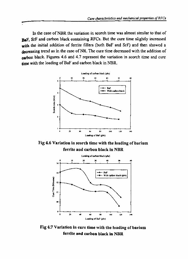
Cure characteristics and mechanical properties of RFCs-In the case ofNBR the variation in scorch time was almost similar to that of
BaF, SrF and carbon black containing RFCs. But the cure time slightly increasedwith the initial addition of ferrite fillers (both BaF and SrF) and then showed adecreasing trend as in the case ofNR. The cure time decreased with the addition of
carbon black. Figures 4.6 and 4.7 represent the variation in scorch time and curetime with the loading of BaF and carbon black in NBR.
Loading or .arbon black (phr)
10 )0 '" SlI 60
--- BaI'-- Wil!l .arbon bl•• k
20 10 IUO IW ''''LDlding orBaI' (phr)
Fig 4.6 Variation in scorch time with the loading of barium
ferrite and carbon black In NBRLolldingofcut>on block (pIIr)
10...)01010o16 t------'"----'---'-------"----'----{
n
i.S 11
~
J... 11
j
'0
~BaF
__ Willl cllbon block (phr)
20 10 100 120 140
Loadin. of BaF (pIu)
Fig 4.7 Variation in cure time with the loading of barium
ferrite and carbon black in NBR
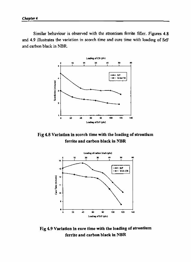
Chapter 4
Similar behaviour is observed with the strontium ferrite filler. Figures 4.8
and 4.9 illustrates the variation in scorch time and cure time with loading of SrF
and carbon black in NBR.
Loadi.. or CB (ph,)
eo4030IDo5 +-_---l...__..l.-_----'-__....l.-_---"__-1
1!.. 3.!i
j
20 40 eo eo lOO
LolIdin.or S,F (phr)
120 140
Fig 4.8 Variation in scorch time with the loading of strontium
ferrite and carbon black in NBR
Loadin. orcarbonblack(pIu)
13
~ 12
.5
.§
.~ 11~
~ 10
10 20 30 eo
1:10lOOeoeo40
e +--~----,--____r--...--..___-.,...._--Io 140
Loadin. or Sri' (phr)
Fig 4.9 Variation in cure time with the loading of strontium
ferrite and carbon black in NOR
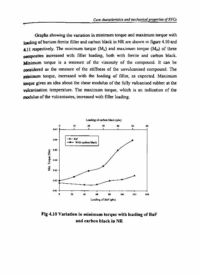
CUte characteristics and mechanical properties of RFCs-Graphs showing the variation in minimum torque and maximum torque with
loading of barium ferrite filler and carbon black in NR are shown in figure4.10 and
4.11 respectively. The minimum torque (Md and maximum torque (MH) of these
composites increased with filler loading, both with ferrite and carbon black.
Minimum torque is a measure of the viscosity of the compound. It can be
considered as the measure of the stiffness of the unvulcanised compound. The
minimum torque, increased with the loading of filler, as expected. Maximum
torque gives an idea about the shear modulus of the fully vulcanised rubber at the
wlcanisation temperature. The maximum torque, which is an indication of the
modulus of the vu1canisates, increased with filler loading.
Loading of carbon black (phr)
6040302010o0.07 +-__.l....-__L-_---..J'--_--l__--l__---l
0.06
E o.os~l!!!' 004
.£J<G 003
0.02
--6- BIf
-- With cubon black
0.01 +-----r--..------r--..------r--..------jo 20 40 60 80 100 120 140
Loading of BaF (phr)
Fig 4.10 Variation in minimum torque with loading of BaF
and carbon black in NR
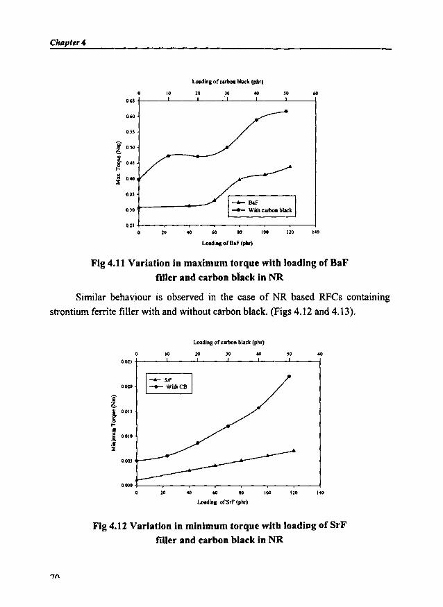
Chllpter4
Loadingof oarboR bl""k (phr)
6050lO2010o0.65 +-__.1-__L.-_.....-.J__-..l.__--I.__-l
0.60
0.55
l 050
i 0.•5I-
~ 0.0:l
0.l5
O.lO
•• 01201006020
0.25 +----.---..----.---..----.---......---lo
Loadingof BaF (phr)
Fig 4.11 Variation in maximum torque with loading of BaFfiller and carbon black in NR
Similar behaviour is observed in the case of NR based RFCs containing
strontium ferrite filler with and without carbon black. (Figs 4.12 and 4.13).
Loadingof oarbonblaok(phr)
6050lO20.0o0.025 +-__-'--__-'--__-'--__-'--__-'--_--4
0020
i~~ O.OIJ
!.1 0010.S::t
0.005
'.0120100106020
0.000 i----..--.....----.---.---.----~-~
o
Loading ofSrF (phr)
Fig 4.12 Variation in minimum torque with loading of SrFfiller and carbon black in NR
'7n
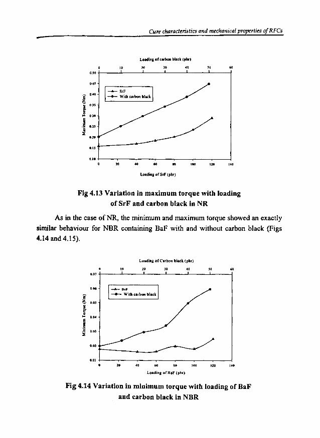
Cure characteristics and mechanical properties of RFCs-Loldina of ....boa bl••k (ph.,
601040lO2010oO.!O +-__..L-__-'-__--L.__~_____l.___f
0.40
l., 0.35
~~ 0.30
.1 0.2!
i0.20
O.!!
140\l01001040100.10 +----..----.---...---_--.-----.------l
o
Loadina of S.f (ph.)
Fig 4.13 Variation in maximum torque with loadingof SrF and carbon black in NR
As in the case ofNR, the minimum and maximum torque showed an exactly
similar behaviour for NBR containing BaF with and without carbon black (Figs4.14 and 4.15).
Fig 4.14 Variation in minimum torque with loading of BaF
and carbon black in NBR

Chapter 4
Fig 4.15 Variation in maximum torque with loading of BaF
and carbon black in NBR
The minimum and maximum torque obtained for the RFC containingstrontium ferrite in NBR, with and without carbon black is shown in figures 4.16and 4.17 respectively. As in the case of RFCs containing BaF both with and
without carbon black, the strontium ferrite filled RFCs also showed an increasingtrend in torque values with the incorporation of the ferrite filler and carbon black.
Loading os CB(phI)
eo40JO2010o0.011 t------'---'----'---L-------'----l
0.021-_------
0.08
0.07
i2:. 005~
! 0.05
9:J 0.04
003
~SIF
-+- Willlc.rnon black
14012010080eo40200.01 +----.----,.--.-----.----T--r---!
oLoading of Srf (phr)
Fig 4.16 Variation in minimum torque with loading of SrF
and carbon black in NBR
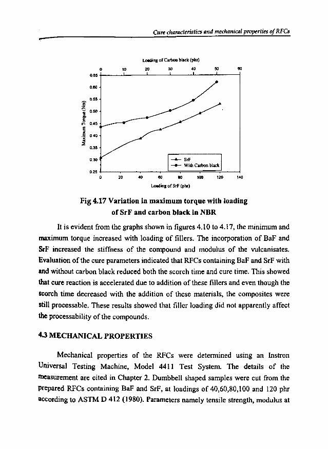
Curecharacteristics and mechanical properties of RFCs
10
u.linl of Carllonblack(phr)
20 30 40 50
0.80
0.55Ezj 050
! 0.45
.1 0.40
~0.3S
0.30 --- SrF-- WilhCarbonblack
140120lOO8080200.2S +----r---...----.-......!::::==;===;==~'---__l
oLoadinl of SrF (phr)
Fig 4.17 Variation in maximum torque with loading
orSrF and carbon black in NBR
It is evident from the graphs shown in figures 4.10 to 4.17, the minimum and
maximum torque increased with loading of fillers. The incorporation of BaF and
SrF increased the stiffness of the compound and modulus of the vu1canisates.
Evaluation of the cure parameters indicated that RFCs containing BaF and SrF with
and without carbon black reduced both the scorch time and cure time. This showed
that cure reaction is accelerated due to addition of these fillers and even though the
scorch time decreased with the addition of these materials, the composites were
still processable. These results showed that filler loading did not apparently affect
the processability of the compounds.
4.3 MECHANICAL PROPERTIES
Mechanical properties of the RFCs were determined using an Instron
Universal Testing Machine, Model 4411 Test System. The details of the
measurement are cited in Chapter 2. Dumbbell shaped samples were cut from the
prepared RFCs containing BaF and SrF, at loadings of 40,60,80,100 and 120 phr
according to ASTM D 412 (1980). Parameters namely tensile strength, modulus at
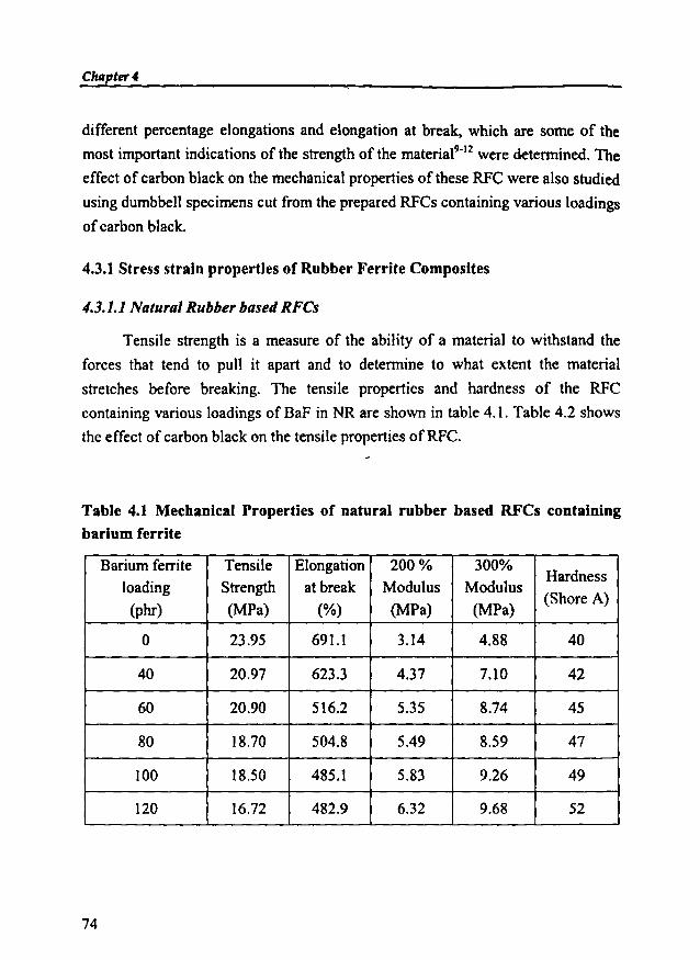
Ch4pter4
different percentage elongations and elongation at break, which are some of the
most important indications of the strength of the materia19-J2 were determined, The
effect of carbon black on the mechanical properties of these RFC were also studied
using dumbbell specimens cut from the prepared RFCs containing various loadings
of carbon black.
4.3.1 Stress strain properties of Rubber Ferrite Composites
4.3.1.1 Natural Rubber based RFCs
Tensile strength is a measure of the ability of a material to withstand the
forces that tend to pull it apart and to determine to what extent the material
stretches before breaking. The tensile properties and hardness of the RFC
containing various loadings of BaF in NR are shown in table 4.1. Table 4.2 shows
the effect of carbon black on the tensile properties ofRFC.
Table 4.1 Mechanical Properties of natural rubber based RFCs containingbarium ferrite
Barium ferrite Tensile Elongation 200% 300%Hardness
loading Strength at break Modulus Modulus(Shore A)
(phr) (MPa) (%) (MPa) (MPa)
0 23.95 691.1 3.14 4.88 40
40 20.97 623.3 4.37 7.10 42
60 20.90 516.2 5.35 8.74 45
80 18.70 504.8 5.49 8.59 47
100 18.50 485.1 5.83 9.26 49
120 16.72 482.9 6.32 9.68 52
74
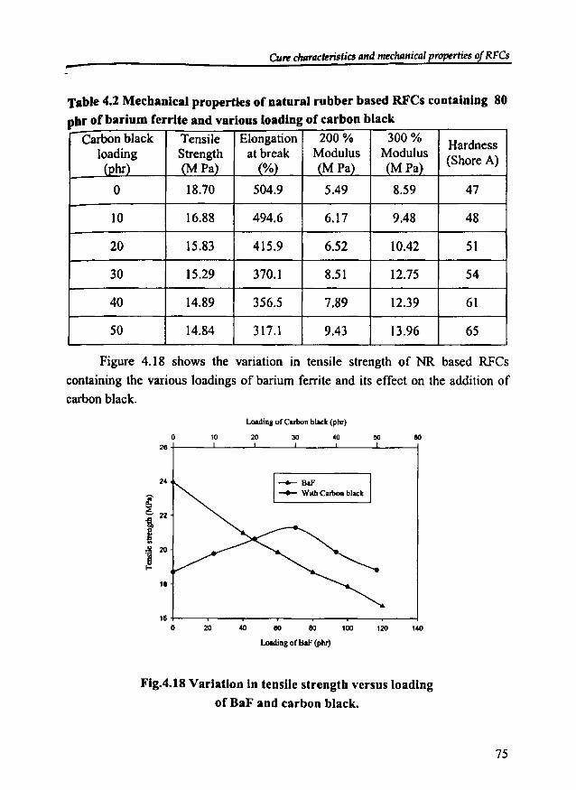
CUr'r duJracteristics andmeclumical properties of RFCs-
Carbon black Tensile Elongation 200% 300% Hardnessloading Strength at break Modulus Modulus (Shore A)
(phr) (MPa) (%) (M Pa) (MPa)
0 18.70 504.9 5.49 8.59 47
10 16.88 494.6 6.17 9.48 48
20 15.83 415.9 6.52 10.42 51
30 15.29 370.1 8.51 12.75 54
40 14.89 356.5 7.89 12.39 61
50 14.84 317.1 9.43 13.96 65
Table 4.2 Mechanical properties of natural rubber based RFCs containing 80pbr of barium ferrite and various loading of carbon black
Figure 4.18 shows the variation in tensile strength of NR based RFCs
containing the various loadings of barium ferrite and its effect on the addition of
carbon black.
Loadinl ofCubon black(phr)
eo302010o26 +------L----'-------''-----'---~-____l
24
11
--- Ba!'__ WithCarbon black
140120100eoeo402016 +-----,--.........----,--,..---"""T"""---r-~
o
1.-ling of BaF (phr)
Fig.4.tH Variation In tensile strength versus loading
of BaF and carbon black.
75

Chapter 4
The variation in tensile strength of NR based RFC containing the various
loading of strontium ferrite and its effect on the addition of carbon black is shown
in figure 4.19.
Loading ofcarbon black (phr)
60so40JO2010o26 +----'-----'-----1..-----'---'"-----1
24
22
~ 20
tt 18....J 16
14
12
~SrF
-- WilhCarbon black
101012010080604020
10+---..---..---~--~-__._---.----I
o
Loading of SrF (phr)
Fig 4.19 Variation in tensile strength versus loadingof SrF and carbon black.
In both the cases the tensile strength decreased with the addition of ferrites.
This is due to the poor interfacial adhesion between the ferrite filler and natural
rubber. Filler reduces the effective cross section of the matrix in the RFC. This
leads to an increase in internal stress, at any given external loading, compared to
that of the unfilled rubber matrix. Stress concentration caused by the filler also
contributes to internal stress. Micro plastic deformation occurs around the filler
particles, which facilitate damage of the material at lower external load, as
compared to the unfilled material". As a consequence of the differential thermal
expansion coefficient, thermally induced internal stresses also occur around the
filler particles. This contributes to an increase of the dewetting stress.
.."
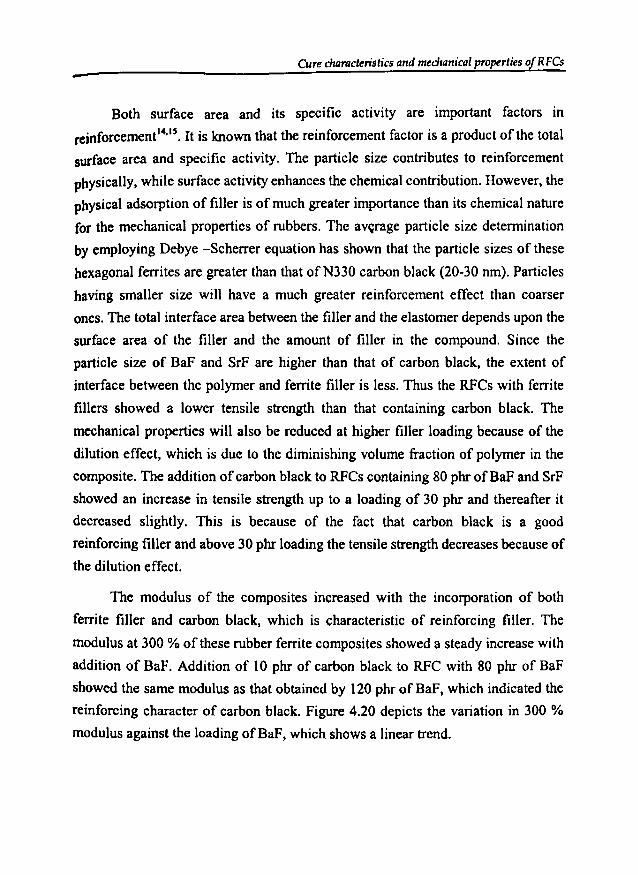
Curecharacteristics and mechanical properties 0 RFCs
Both surface area and its specific activity are important factors in
reinforcement I4•1S
• It is known that the reinforcement factor is a product of the total
surface area and specific activity. The particle size contributes to reinforcement
physically, while surface activity enhances the chemical contribution. However, the
physical adsorption of filler is of much greater importance than its chemical nature
for the mechanical properties of rubbers. The average particle size determination
by employing Debye -Scherrer equation has shown that the particle sizes of these
hexagonal ferrites are greater than that ofN330 carbon black (20-30 nm). Particles
having smaller size will have a much greater reinforcement effect than coarser
ones. The total interface area between the filler and the elastomer depends upon the
surface area of the filler and the amount of filler in the compound. Since the
particle size of BaF and SrF are higher than that of carbon black, the extent of
interface between the polymer and ferrite filler is less. Thus the RFCs with ferrite
fillers showed a lower tensile strength than that containing carbon black. The
mechanical properties will also be reduced at higher filler loading because of the
dilution effect, which is due to the diminishing volume fraction of polymer in the
composite. The addition of carbon black to RFCs containing 80 phr ofBaF and SrF
showed an increase in tensile strength up to a loading of 30 phr and thereafter it
decreased slightly. This is because of the fact that carbon black is a good
reinforcing filler and above 30 phr loading the tensile strength decreases because of
the dilution effect.
The modulus of the composites increased with the incorporation of both
ferrite filler and carbon black, which is characteristic of reinforcing filler. The
modulus at 300 % of these rubber ferrite composites showed a steady increase with
addition of BaF. Addition of 10 phr of carbon black to RFC with 80 phr of BaF
showed the same modulus as that obtained by 120 phr of BaF, which indicated the
reinforcing character of carbon black. Figure 4.20 depicts the variation in 300 %
modulus against the loading of BaF, which shows a linear trend.

Chapter 4
Loadingof carbonblack(phr)
60'040302010o15 r;:::::====~--L__--L-__L....--I
13
'i 12
6 11
11 10
i 9
~ 8g...
11
5
• BaF• WithCarbonblack
140120100604020
4 -j----r----,---r--.,.----,------,r---;o
Loadingof BaF(phr)
Fig 4.20 Variation in modulus at'300 % elongation againstthe loading of BaF and carbon black
The mechanical properties of the RFC containing various loadings of SrF in
natural rubber are shown in table 4.3. Table 4.4 shows the effect of carbon black on
the mechanical properties of RFC.
Table 4.3 Mechanical properties of natural rubber based RFCs containing
strontium ferrite
Strontium ferrite Tensile Elongation 200% 300%Hardness
loading strength at break Modulus Modulus(Shore A)
(phr) (MPa) (%) (MPa) (MPa)
0 23.95 691.2 3.14 4.88 40
40 13.82 687.9 1.29 5.30 44
60 12.75 615.8 1.67 5.90 47
80 12.49 606.7 1.94 6.10 50
100 10.97 506 2.76 7.09 55
120 10.88 496 2.78 8.05 58
78
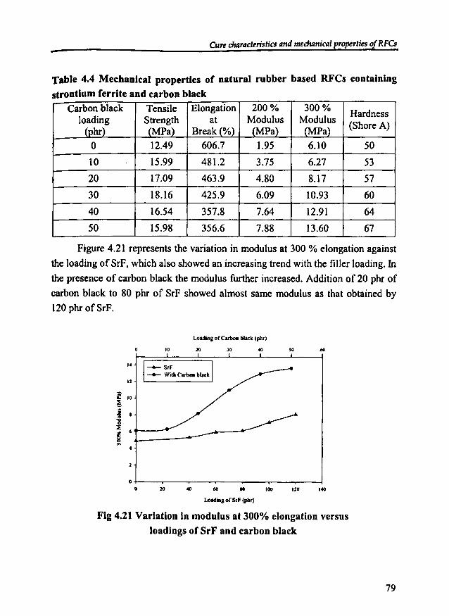
Cure dutracteristics andmeclumical properties of RFCs
Table 4.4 Mechanical properties of natural rubber based RFCs containing
strontium ferrite and carbon blackCarbon black Tensile Elongation 200% 300%
Hardnessloading Strength at Modulus Modulus
(Shore A)(phr) (MPa) Break(%) (MPa) (MPa)
0 12.49 606.7 1.95 6.10 50
10 15.99 481.2 3.75 6.27 53
20 17.09 463.9 4.80 8.17 57
30 18.16 425.9 6.09 10.93 60
40 16.54 357.8 7.64 12.91 64
50 15.98 356.6 7.88 13.60 67
Figure 4.21 represents the variation in modulus at 300 % elongation against
the loading ofSrF, which also showed an increasing trend with the filler loading. In
the presence of carbon black the modulus further increased. Addition of 20 phr of
carbon black to 80 phr of SrF showed almost same modulus as that obtained by
120 phr of SrF.
Loading ofCorbon black (phr)
10 20 lO so 60
f 10
~! .~ 'P---
...
.4
u
-A- StF
-- With Corbon bl••k
'40120'006020
o+--..........----.-----r-----,..---.,-----,-----1o
Loading ofSrF (pbr)
Fig 4.21 Variation in modulus at 300% elongation versusloadings of SrF and carbon black
79
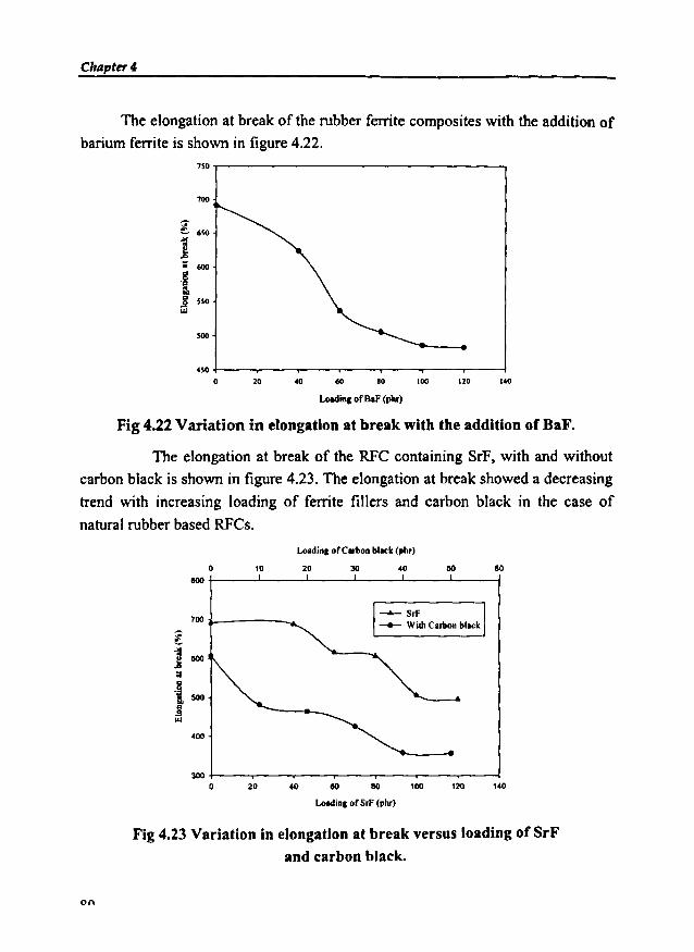
Chapter 4
The elongation at break of the rubber ferrite composites with the addition of
barium ferrite is shown in figure 4.22.750,....------------------,
1201001020
.50 +----.---..-----.---.-----.---.-----1o
700
l 6JO
];; 600
.§a.~ 550
Loading of OaF (phr)
Fig 4.22 Variation in elongation at break with the addition of BaF.
The elongation at break of the RFC containing SrF, with and without
carbon black is shown in figure 4.23. The elongation at break showed a decreasing
trend with increasing loading of ferrite fillers and carbon black in the case of
natural rubber based RFCs.
Loadins of Carbon bllck (ph,)
30
--- S,F-- WilhCarbon bllck
IlO
140120100IlO
20
40
10
20
0eoo
700
l-':l
IlOO...B118"i 500
".9III
400
3000
LoadinS of SrF (phr)
Fig 4.23 Variation in elongation at break versus loading of SrFand carbon black.
o{\
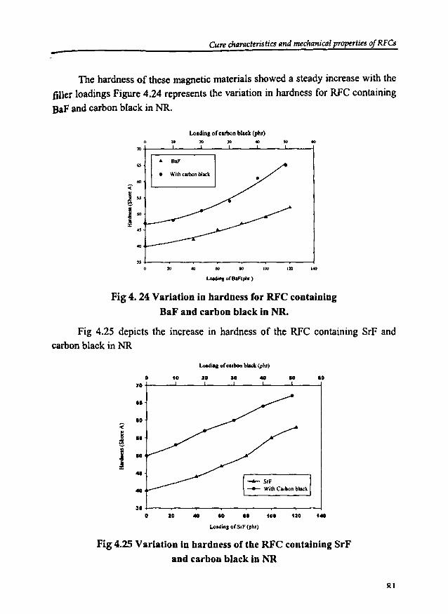
Curecharacteristics and mechanical properties 0 RFCs
The hardness of these magnetic materials showed a steady increase with the
filler loadings Figure 4.24 represents the variation in hardness for RFC containing
BaP and carbon black in NR.
..Loadinl or carbonblack (phr)10 10 )0 40o.,.+--_---'-__...L-_--Jl.-_~__..L__ __l
.. BaF
• Wilh<a,bon block..
.,
..,...20""10so20
n+---..---..----,--~-_._-_._-__.j
o
Loadin. of BaF(phr )
Fig 4. 24 Variation in hardness for RFC containing
BaF and carbon black in NR.
Fig 4.25 depicts the increase in hardness of the RFC containing SrF andcarbon black in NR
Loldia, or carbon!>lICk (phr)
-A- Srf-- With C.rbon black
a70..I.
:(; ..~e I.~
41
40
al0
to
ID
2. ID
I. 100
10
120
la
140
Loldinll orS,F (ph,)
Fig 4.25 Variation in hardness of the RFC containing SrFand carbon black in NR
Sl.1

Chapter 4
Addition of20 phr carbon black to the RFC with 80 phr offerrite filler showed
an equivalent hardness to that containing 120 phr of BaF or SrF. This indicated that
the carbon black is enhancing the hardness of the composites, which is on expected
lines. Even after the addition of 50 phr of carbon black to RFCs containing 80 phr of
ferrite filler, they found to be flexible and serviceable. This property can be exploited
to make flexible magnets suitable for various applications.
4.3.1.2 Nitrile rubber based RFCs
The mechanical properties of the RFC containing various loadings of BaF in
nitrile rubber are shown in table 4.5. Table 4.6 shows the effect of carbon black on
the tensile properties of RFC. Figure 4.26 shows the variation in tensile strength of
RFC with the loading ofbarium ferrite and carbon black.
Table 4.5 Mechanical Properties of nitrile rubber based RFCs containing
barium ferrite
Barium ferrite Tensile Elongation 200% 300%Hardness
loading strength at break Modulus Modulus(Shore A)
(phr) (MPa) (%) (MPa) (MPa)
0 2.13 465.9 1.74 2.09 55
40 2.93 456.0 1.78 2.10 58
60 3.12 445.0 1.79 2.11 62
80 3.29 439.9 1.83 2.14 6S
100 3.44 394.0 1.87 2.14 67
120 3.26 304.7 1.90 2.24 69
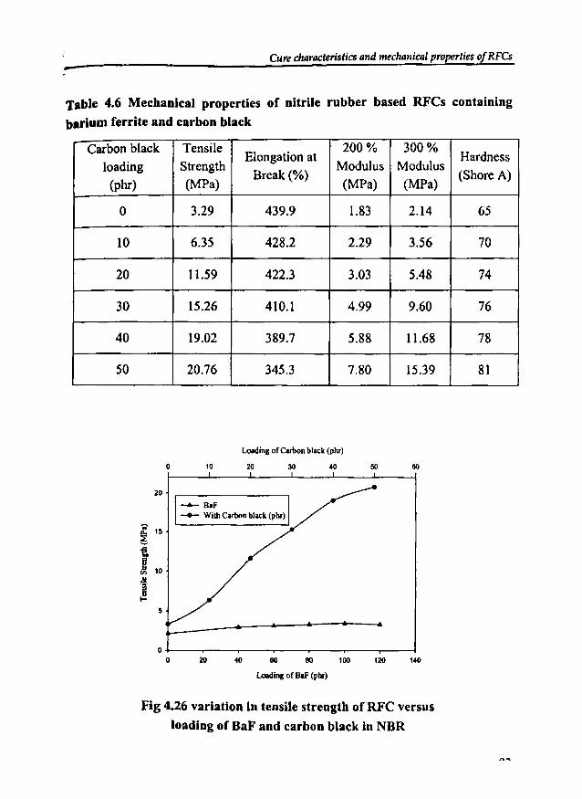
Cure c1ulracteristics and mechanical properties of RFCs-Table 4.6 Mechanical properties of nitrile rubber based RFCs containing
barium ferrite and carbon black
Carbon black TensileElongation at
200% 300%Hardness
loading Strength Modulus ModulusBreak(%) (Shore A)
(phr) (MPa) (MPa) (MPa)
0 3.29 439.9 1.83 2.14 65
10 6.35 428.2 2.29 3.56 70
20 11.59 422.3 3.03 5.48 74
30 15.26 410.1 4.99 9.60 76
40 19.02 389.7 5.88 11.68 78
50 20.76 345.3 7.80 15.39 81
Loacling of Carbon black (phr)
0 10 20 30 40 50 60
20
~ 15
i.R 10.!!.~
...5
00 20 40 60 eo 100 120 140
Loacling of DaF(phr)
Fig 4.26 variation In tensile strength of RFC versus
loading of BaF and carbon black in NBR
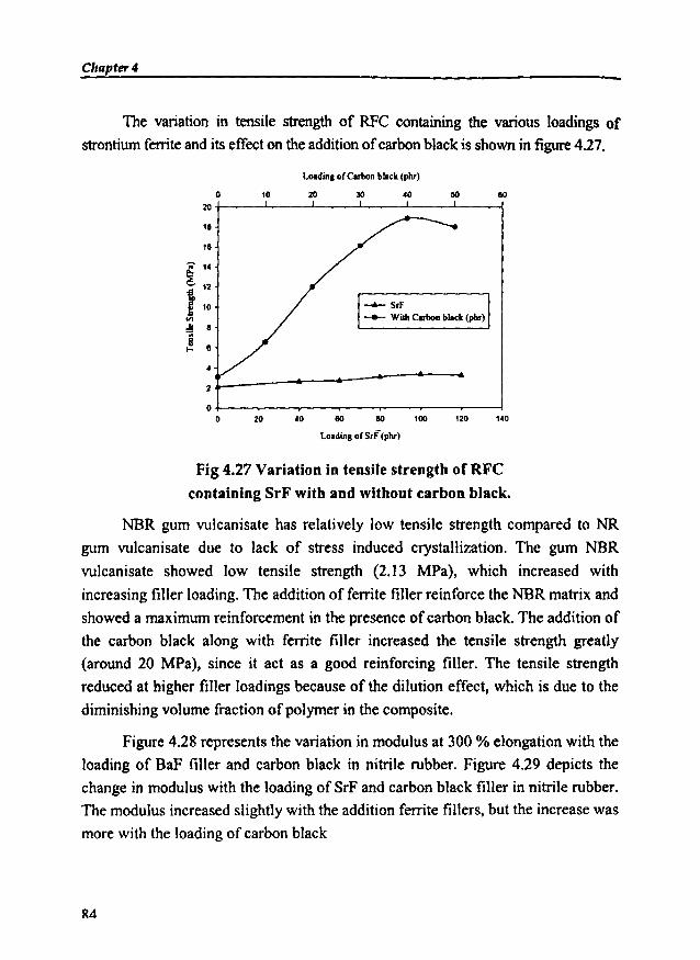
Chapter 4
The variation in tensile strength of RFC containing the various loadings of
strontiumferriteand its effect on the addition ofcarbon black is shown in figure 4.27.
L...dinll orCltbon black (ph<)
co2010o20+-----'----'-----''----'-----'----1
11
2
--+- S,F__ Wilh Cltbon black (ph,)
lCO'20'00eoco20o~--,--~-___._--..__-_r_--T""----l
otOldinS or s,i'(ph<)
Fig 4.27 Variation in tensile strength ofRFC
containing SrF with and without carbon black.
NBR gum vulcanisate has relatively low tensile strength compared to NR
gum vulcanisate due to lack of stress induced crystallization. The gum NBR
vulcanisate showed low tensile strength (2.13 MPa), which increased with
increasing filler loading. The addition of ferrite filler reinforce the NBR matrix and
showed a maximum reinforcement in the presence of carbon black. The addition of
the carbon black along with ferrite filler increased the tensile strength greatly
(around 20 MPa), since it act as a good reinforcing filler. The tensile strength
reduced at higher filler loadings because of the dilution effect, which is due to the
diminishing volume fraction ofpolymer in the composite.
Figure 4.28 represents the variation in modulus at 300 % elongation with the
loading of BaF filler and carbon black in nitrile rubber. Figure 4.29 depicts the
change in modulus with the loading of SrF and carbon black filler in nitrile rubber.
The modulus increased slightly with the addition ferrite fillers, but the increase was
more with the loading of carbon black
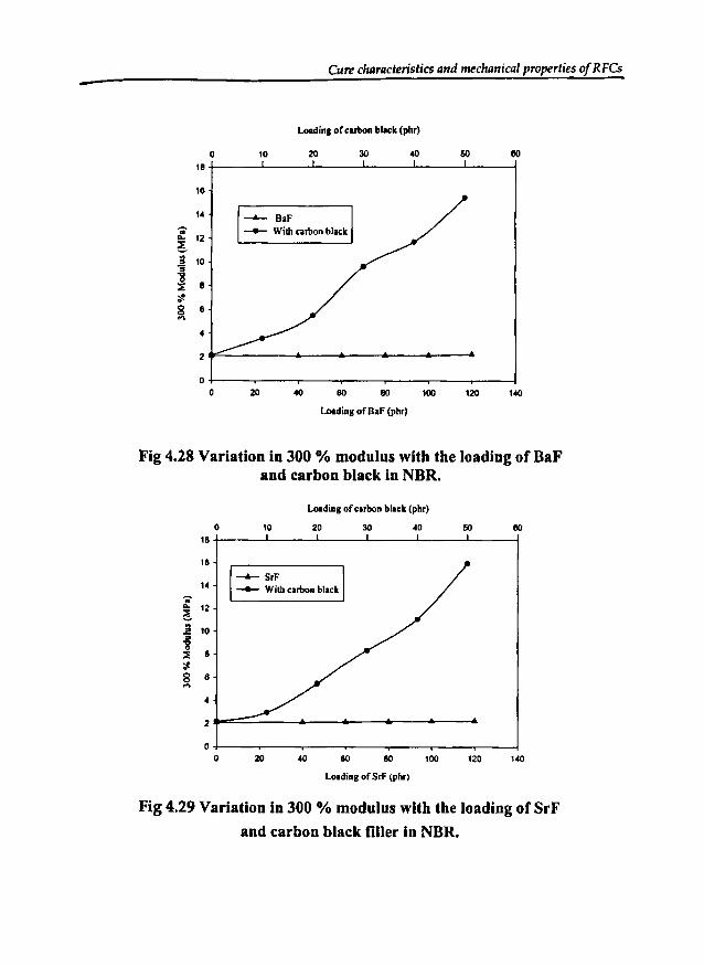
--Cure cluJracteristics and mechanical properties of RFCs
Loading ofcarbon bl..,k (phr)
0 10 20 30 40 60 eo18
16
14~ BaF... -- Wilh carbon black
ll- 126jg 10'3-g
8::E~g 6....
4
2
00 20 40 eo 80 100 120 140
Loading of OaF (phr)
Fig 4.28 Variation in 300 % modulus with the loading of BaFand carbon black In NBR.
loading of carbon black (phr)
0 10 20 30 4D 50 eo18
16
~SrF14
-- Wilh carbon black...ll- 12!
j 10
::E 8
~
8 6....4
2
00 20 40 50 eo 100 120 140
loading ofSrF (phr)
Fig 4.29 Variation in 300 % modulus with the loading of SrF
and carbon black filler in NBR.
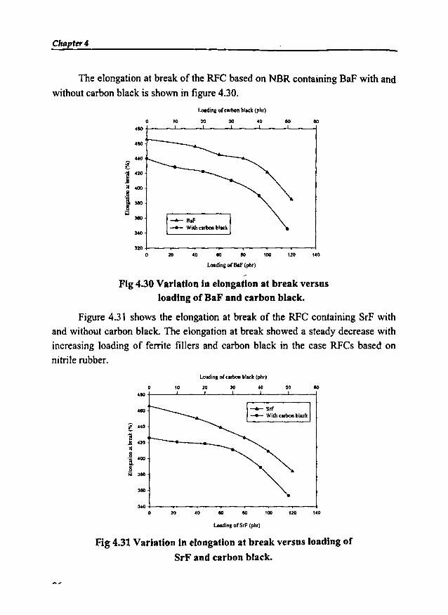
C1uJpter4
The elongation at break of the RFC based on NBR containing BaF with and
without carbon black is shown in figure 4.30.
Looding of cubon block (ph,)
eo5040302010o480 +-_--'-__-'- '----_--L-__-'-_~
41\0
-- Raf-- With mbon bll<k
340
140120100eo4020
320 ~-...,.....-__._-____.--,._-_,_-_._-__lo
Loadin& of8IF (ph,)
Fig 4.30 Variation in elongation at break versusloading of BaF and carbon black.
Figure 4.31 shows the elongation at break of the RFC containing SrF with
and without carbon black. The elongation at break showed a steady decrease with
increasing loading of ferrite fillers and carbon black in the case RFCs based on
nitrile rubber.
Loldinl of CII,bon black (ph,)
8040302010o480 t----'----'-------!---.1.----i
480
! 410
] 420r-----__...g 400
j_ 380
3110
"'--S,F__ Wilh tllbon bla<k
140.2010080eo4020340 +--~-_._-_...--.__-_.__-~-~
o
Loldi_. of S,F (ph,)
Fig 4.31 Variation In elongation at break versus loading of
SrF and carbon black.
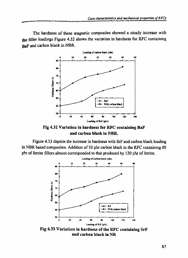
Curecharacteristics and mechanical properties of RFCs-The hardness of these magnetic composites showed a steady increase with
the filler loadings Figure 4.32 shows the variation in hardness for RFC containing
BaF and carbon black in NBR.
LoadilIlIohllllon black (phr)
50302010oM+-----'--~---'------'--~-__l
80
75
<j 70~
12040 80 lIO 100
loadinll ofBaF (ph,)
2050 +----r---.---.-----.---.------..----I
o
Fig 4.32 Variation in hardness for RFC containing UaFand carbon black in NUR.
Figure 4.33 depicts the increase in hardness with SrF and carbon black loading
in NBR based composites. Addition of 10 phr carbon black to the RFC containing 80
phr of ferrite fillers almost corresponded to that produced by 120 phr of ferrite.Loading orcllllon black (ph,)
80503010olIIit-----J.--....J.---"------'----'--------j
-6- S,f__ Wi!hcubon black
10080205O+---,-.----r----,---.----.----.--~
oLoading orS,f (ph,)
Fig 4.33 Variation in hardness of the RFC containing SrFand carbon black in NR
87
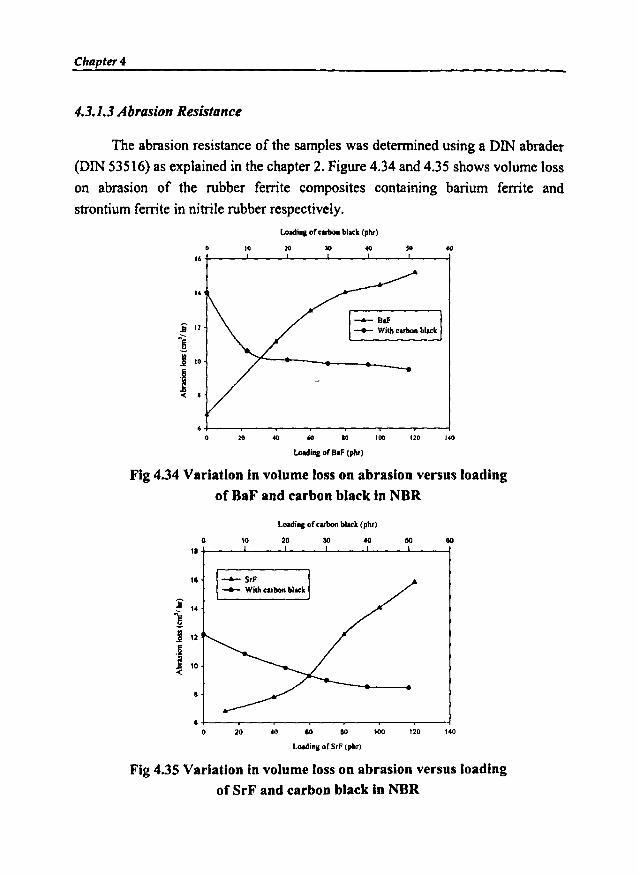
Chapter 4
4.3.1.3 AbrasionResistance
The abrasion resistance of the samples was determined using a DIN abrader
(DIN 53516) as explained in the chapter 2. Figure 4.34 and 4.35 shows volume loss
on abrasion of the rubber ferrite composites containing barium ferrite and
strontium ferrite in nitrile rubber respectively.
Loadin. of .arbon black (phr)
60'01010o16t-----'-----'---L..---.L----'-----j
.i 11
1j 10
j-e •
-.-- DoF__ Wilh.atbon black
1401201006020
6+--~-_._-___.--...__-~-~---i
o
Loadine of D.F (pM)
Fig 4.34 Variation in volume loss on abrasion versus loadingof BaF and carbon black in NBR
Loadin. of ."bon bl.ck (ph,)
80
140120100
40
8080
2010
11
olat----'---'---..L----'---'-----j
Loading of SrF (phrl
Fig 4.35 Variation in volume loss on abrasion versus loadingof SrF and carbon black in NBR

CurecharacteristiCS and mechanical properties of RFCs
The abrasion loss showed an increasing trend with the loading of ferrite
fillers whereas in the case of rubber ferrite composites' containing various loading
of carbon black it was less. This is because the particle size of carbon black is finer
than that of ferrite fillers. Thus it is possible to produce flexible magnets for
various applications, which requires high abrasion resistance by the incorporation
of different loading ofcarbon black.
4.4 CONCLUSION
The studies on cure characteristics of rubber ferrite composites indicated that
the addition of magnetic fillers reduces both the scorch time and cure time. The
minimum and maximum torque values increased with the increasing loading of
ferrite filler and carbon black. Even though the scorch time decreased and the
torque values increased with the addition of these fillers, the processability of these
composites were not affected. The mechanical properties of the rubber ferrite
composites can be enhanced by the incorporation of appropriate amount of ferrite
filler and carbon black. The evaluation of cure characteristics and mechanical
properties revealed that the processability and flexibility of the matrix was not
much affected even up to a loading of 120 phr of ferrite fillers.
Chapter 4
REFERENCES
1. Safari Ardi M, Dick Wand McQueen D.H, Plastic Rubber and Composites
Processing Applications, 24 (1995) 157-164.
2. Anantharaman M. R, S. Jagatheesan, S. Sindhu, K. A. Malini, C. N. Chinnasamy,
A. Narayansamy, P. Kurian and K. Vasudevan, Plastic Rubber and Composites
Processing Applications, 27, 2, (1998) 77-81.
3. Anantharaman M.R, S. Sindhu, S. Jagatheesan, K.A. Malini and Philip Kurian,
Journal ofPhysics D Applied Physics 32 (1999) 1801·1810.
4. Mohammed E.M et al, Materials Research Bulletin 37 (2002) 753-768.
5. Katz H. Sand J. V. Milewski, 'Handbook of Reinforcement of Plastics',
1978, Vannostrand Reinhold, New York.
6. Praveen Singh & T.e. Goel: Indian 1.!\Jre and AppI Phys., 38 (2000) 213-219.
7. Anantharaman M. R, P. Kurian, B. Banerjee, E. M. Mohammed, and M.
George, Kautschuk Gummi Kunststoffe, (Germany), 49, 6/96, 424- 426.
8. Ananthararnan M. R, K.A. Malini, S. Sindhu, E.M. Mohammed, S.K Date, S.D.
Kulkarni, P.A. Joy, and Philip Kurian, Bull. Mater. Sci., 24,6 (200 I) 623-631.
9. Steven Blow. Handbook ofRubber Technology, Galgotia Publishing Pvt. Ltd. 1998.
10. Allen. W, Natural Rubber and the Synthetics, Granada Publishing Ltd. 1972.
11. Vishu Shah, Handbook of plastic testing technology, John Wiley and sons
Inc., USA 1998.
12. Charles A Harper, Handbook of Plastic, Elastomers and Composites (2nd
Edition) McGraw Hi11 Inc. 1992.
13. VolIenberg. P, D.Heikens and H.C.B.Laden: Polymer Composites, 9 (1988) 382.
14. Blow C.M. and C.Hepbum, 'Rubber Technology and Manufacture', 2nd
edition, (1985), Butterworths Publishers, London
15. Roberts. A.D, Natural Rubber Science and Technology, 1998, Oxford
University Press, New York 556.
90

ChapterS
DIELECTRIC PROPERTIES OF RUBBERFERRITE COMPOSITES
5.1 INTRODUCflON
Rubber ferrite composites are composite magnetic materials, which have the
unique advantage of being modified so as to tailor make materials for specific
applications. Generally composites can offer a combination of properties and a
diversity of applications to produce materials that surpasses the performance of the
individual components. Thus the composites can be designed to exploit the best
properties of the constituents. Rubber ferrite composites prepared by incorporating
ferrites in rubber matrixes are increasingly being used as microwave absorbers and
in other devices where flexibility and mouldability is an important criterion. RFC
utilises this property of the polymer matrix along with the dielectric properties of
the magnetic fillers to obtain a combination of predetermined dielectric and
mechanical properties required for definite applications. The dielectric and
mechanical properties can be enhanced by the addition of required amount of
carbon black. Dielectric measurements on materials provide valuable informationabout the matrix filler interaction, dispersion of filler and percolation threshold 1.3,
which are important designing parameters for application such as electromagnetic
wave absorbers, EM! shielding materials 4.S and many electronic applications 6-10.
It has been known that the dielectric properties of polycrystalline materials
are influenced by factors like preparative techniques, cation distribution, grain size,
<)1

Chapter 5
the ratio of Fe3+IFe2
+ ions, ac conductivity and sintering temperature 11.12. The
dielectric properties of ceramic ferrite samples are also influenced by various
factors like method of preparation, sintering conditions, ionic charge, chemical
composition and grain size. The dependence of these factors on the dielectric
properties of ceramic fillers will have a profound influence on the overall physical
properties of the composites 13,14. When ferrites are fired at higher temperature it is
possible that films of high resistivity over the constituent grains are formed. Such
materials in which the individual grains are separated either by air gaps or by low
conducting layers behave as a heterogeneous dielectric material.
The evaluation of dielectric, structural and magnetic properties of the ceramic
BaF, SrF and RFCs are important since the interrelationship of the properties of the
filler and the matrix will help in the design ofdevices for various applications.
RFCs containing BaF and SrF in natural and nitrile rubber matrix were
prepared and their dielectric properties were evaluated. The ceramic ferrite samples
were prepared by conventional solid-state reactions. Their incorporation in natural
and nitrile rubbermatrix was achieved according to a specific recipe. The details of
preparation are cited in chapter 3. The variation in dielectric constant with
frequency for the ceramic ferrite and RFCs were studied. The effect of loading of
ferrite fillers and temperature on the dielectric constant of the composites was also
studied and the results were correlated in this chapter.
The effect of carbon black on the dielectric properties of the rubber ferrite
composites containing 80 phr of ferrite filler was also studied.
5.2 DIELECTRIC MEASUREMENTS
The dielectric constants of both ceramic and composite samples were
evaluated using a dielectric cell and an impedance analyser (Model: HP 4285A).
The dielectric measurements were carried out at different frequencies ranging from
100 KHz to 8 MHz. This was repeated for different temperatures ranging from
303K to 393K.
0")

Dielectric Properties of RFCs-5.2.1 Ceramic samples
The dielectric constant of BaP and SrF samples were determined using an
experimental set up as described in chapter 2. The samples were made in the form of
pellets using a hydraulic press by exerting a pressure of 9 tons. These circular disc
pellets having a diameter of IOmm was loaded into the dielectric cell. The lead and
fringe capacitance was eliminated by a method described by Ramasastry and
Syamasundara Rao IS. The capacitances at 303K were measured in the frequency range
100KHz to 8 MHz. This was repeated at different temperatures of313K, 333K, 353K,
373K, and 393K. The dielectric constant, Er was calculated using the formula
C = EO Er AId (5.1)
Where A is area ofsample piece used, d is the thickness of the sample, Er is the
dielectric constant of the medium and Eo is the dielectric constant of air and C is the
observed capacitance of the sample. Dielectric constants at various temperatures and
frequencies were also determined. Knowledge of dielectric properties of the ceramic
samples at various frequencies and temperatures was considered as a prerequisite,
since the same material has to be incorporated in the rubber matrix.
5.2.1.1 Effect of'frequency on dielectric properties
In ferrite materials, very high dielectric constant at very low frequencies,
have been reported by various researchers 16-20. The reported values for dielectric
constant of ceramic samples show that the dielectric constant fall from a dc value
of several thousands to the normal values of the order of tens for a frequency of
around 100 KHz. These results have been explained by Koops phenomenological
theory and Maxwell-Wagner interfacial polarization 16,21.
The dielectric constants of the ceramic samples of BaF and SrF versus
frequency were plotted at different temperatures and are shown in figures 5.1 and
5.2. A decrease in dielectric constant with increase of frequency was observed in
this case also. This decrease was rapid at lower frequencies (up to 2MHz) and
slower at higher frequencies. The dielectric constant measurements were made up
to a maximum frequency of 8 MHz. The variation pattern remained the same for
both BaF and SrF. The dielectric constant ofBaF decreased from 25.85 at 100 KHz

ChapterS
to 7.92 at 8 MHz whereas that of SrF decreased from 21.5 t09.26 in the samefrequency range.
~o
35
30~13g 25Uu.~ 20
~__ lO3K
-- 313K15~l33K
-- 3S3K10 __ 373K
-- 393K5
5.0 5.5 11.0
Log frequency(Hz)-
Ceramic Bal'
11.5 7.0
Fig 5.1 Dielectric constant (e) of ceramic BaF versus log frequency (Hz)at different temperatures
211
24 Ceramic SrF
22
~ 20
g18
U
" -- 303K'§ 111-- 313K'ii
is 14__ 33lK__ 353K
12__ 373K
__ 393K
10
85.0 55 8.0 11.5 7.0
Log frequency(Hz)
Fig 5.2 Dielectric constant (E) of ceramic SrF versus log frequency (Hz)
at different temperatures.
The observed decrease in dielectric constant with increase in frequency can
be explained using Koop's phenomenological theory of dispersion 21, which is
based on Maxwell Wagner theory of interfacial polarization. It is assumed that the

Dielectric Properties of RFCs
-dielectric structure of ferrites is formed in two layers, namely, the well conducting
pins and poorly conducting grain boundaries. At very low frequencies the oxide
grain boundaries are more active and this contributes to the very high dielectric
constant at low frequencies. A general relation of the following form explains the
variation ofdielectric constant with frequency.
ell =( r -rl)(el x (0) (5.2)
where &1 and ell are the real and imaginary part of the dielectric constant, rand r l
are the ac and de conductivities respectively, and 00 is the angular frequency which
is equal to 2nf, where f is frequency of the applied field.
5.2.1.2 Effect oftemperature on dielectric properties
The effect of temperature on the dielectric constant for the ceramic samples
was studied in the temperature ranging from 303K to 393K. At this temperature
range the permittivity value ofBaF increased from 25.85 to 33.76 at 1KHzand that
of SRF increased from 21.50 to 24.90. The variation in dielectric constant with
temperature for ceramic BaF and SrF are shown in figures 5.1 and 5.2 respectively.
It was observed that the dielectric constant of ceramic samples increased with
increase of temperature. In dielectrics, the dielectric constant increases with
temperature because of the increase in ionic polarization". The high dielectric
constants at low frequencies and high temperatures can be explained by the
presence of permanent dipole moments indicating a small effective charge
separation. Such a small separation must be due to asymmetry in the fields
experienced by either oxygen or metallic ions. In most cases, the atoms or
molecules in the samples cannot orient themselves at low temperature region.
When temperature rises the orientation of these dipoles is facilitated and this
increases the dielectric polarization. But at very high temperature the chaotic
thermal oscillations of molecules are intensified and the degree of orderliness of
their orientation is diminished and thus the permittivity passes through a maximum
value. In the present study the maximum temperature of measurement was only
393K and no decrease in dielectric constant was observed. Higher temperatures
were not considered in these experiments, since the upper service temperature
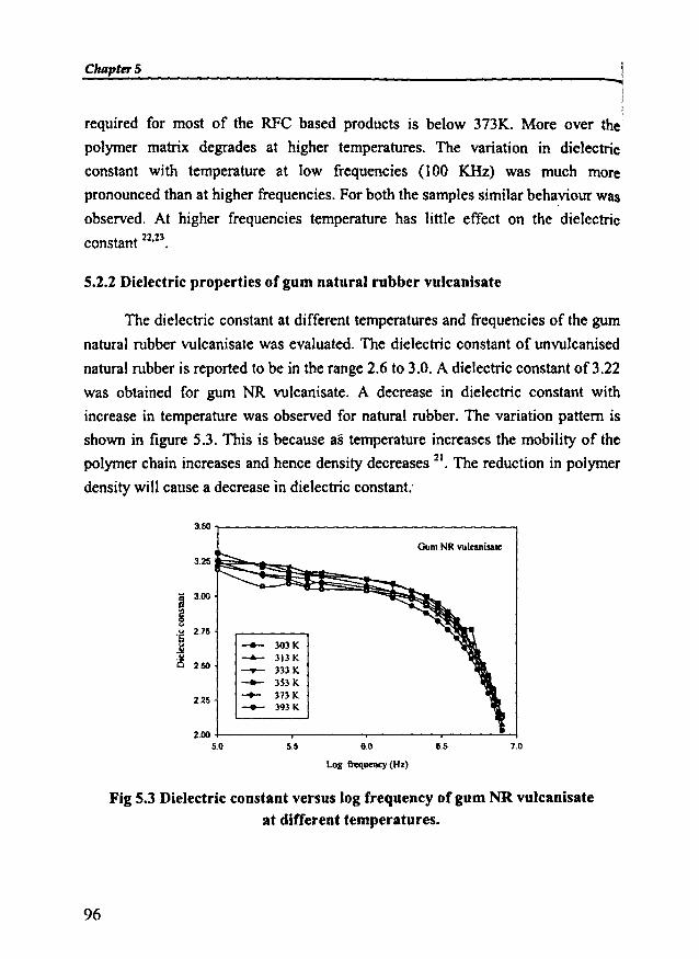
ChapterS ....
required for most of the RFC based products is below 373K. More over the
polymer matrix degrades at higher temperatures. The variation in dielectric
constant with temperature at low frequencies (100 KHz) was much more
pronounced than at higher frequencies. For both the samples similar behaviour was
observed. At higher frequencies temperature has little effect on the dielectricconstant 22.23.
5.2.2 Dielectric properties of gum natural rubber vulcanisate
The dielectric constant at different temperatures and frequencies of the gum
natural rubber vulcanisate was evaluated. The dielectric constant of unvulcanised
natural rubber is reported to be in the range 2.6 to 3.0. A dielectric constant of3.22
was obtained for gum NR vulcanisate. A decrease in dielectric constant with
increase in temperature was observed for natural rubber. The variation pattern is
shown in figure 5.3. This is because as temperature increases the mobility of the
polymer chain increases and hence density decreases 21. The reduction in polymer
density will cause a decrease in dielectric constant:
3.50
3.25
a 3.00
g...... 2.75'Sjuis 2.50
2.25
2.005.0
-- lOlK--6-- 113 K-.- 3l3K-- lSl K-- 17l K-- 191 K
55 6.0
Log frequency(Hz)
GumNR vulcanisale
6.5 7.0
Fig 5.3 Dielectric constant versus log frequency of gum NR vulcanisateat different temperatures.
96
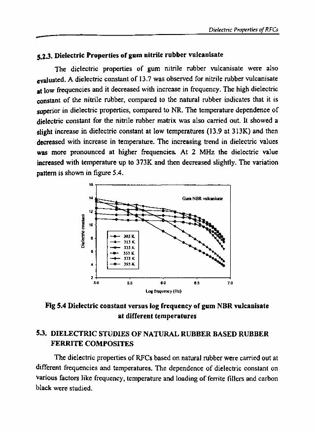
Dielectric Properties of RFCs-5.2.3. Dielectric Properties of gum nitrile rubber vulcanisate
The dielectric properties of gum nitrile rubber vulcanisate were also
evaluated. A dielectric constant of 13.7 was observed for nitrile rubber vulcanisate
at low frequencies and it decreased with increase in frequency. The high dielectric
constant of the nitrile rubber, compared to the natural rubber indicates that it is
superior in dielectric properties, compared to NR. The temperature dependence of
dielectric constant for the nitrile rubber matrix was also carried out. It showed a
slight increase in dielectric constant at low temperatures (13.9 at 313K) and then
decreased with increase in temperature. The increasing trend in dielectric values
was more pronounced at higher frequencies. At 2 MHz the dielectric value
increased with temperature up to 373K and then decreased slightly. The variation
pattern is shown in figure 5.4.
18,-----------------,
-- 303K~ 313K__ 333K
--- 3S3 K__ 373K
-- 393K4
8
14r:S~~;:s~::;;::::~:=::",,~ Gum NORwlcanisate
7.08.58.0
Log l'rcqumcy (Hz)
5.52 +----...,......-----.-----,....----l
5.0
Fig 5.4 Dielectric constant versus log frequency of gum NBR vulcanisate
at different temperatures
5.3. DIELECTRIC STUDIES OF NATURAL RUBBER BASED RUBBERFERRITE COMPOSITES
The dielectric properties of RFCs based on natural rubber were carried out at
different frequencies and temperatures. The dependence of dielectric constant on
various factors like frequency, temperature and loading of ferrite fillers and carbonblack were studied.

Chapter 5
5.3.1 Rubber Ferrite Composites containing barium ferrite
The RFCs containing BaF in natural rubber was prepared as cited in chapter
3. The dielectric properties of these RFCs and the effect of the addition of carbon
black were studied in detail.
5.3.1.1 Effect offrequency on dielectric properties ofRFC
The dielectric properties of natural rubber based RFCs with change in
frequency at different temperatures were carried out in detail. Almost similar
behaviour as that of the ceramic component present in the matrix was obtained in
the case of RFCs. The absolute values of the dielectric constant of the composites
were found to be greater than that of the gum NR vulcanisate, but less than that of
the ceramic BaF. It can be seen that the dielectric constant decreased with
frequency for composites containing different loadings of BaF. This behaviour is in
accordance with the Maxwell Wagner theory of interfacial polarization. Figures
5.5a to 5.5e shows the variation in dielectric constant of RFC with frequency at
different temperatures.
5.0
4.5
~4.0
l'J0u
'S 3.5
~ __ 30JK
"Q 3.0 .-.- 313K......- 333K__ 3S3K
2.5 -+- 373K__ 393K
2.05.0 5.5 6.0
Log ~uency (Hz)
40phr OaF
6.5 7.0
Fig S.Sa Dielectric constant versus log frequency of NR based RFCcontaining 40 phr BaF at different temperatures
9R
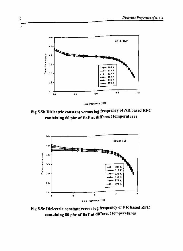
-Dielectric Properties of RFCs
60 phr BaF
5.0
4.5
;; 4.01320uu 3.5..6uJ/..i:'5 3.0
2.5
2.05.0 5.5
__ 303 K
-...- 313 K__ 333 K__ 3S3K
........ 3731<.___ 393 K
6.0
Log frequency (Hz)
6.5 7.0
Fig 5.5b Dielectric constant versus log frequency of NR based RFCcontaining 60 phr of BaF at different temperatures
5.0
4.5
;; 4.0S...,0uu 3.5S.....:iCl 3.0
2.5
2.05 6
sephr BaF
_303K___ 31) K
.........- 333 K_)53K_ 37JK
_393K
6
Log rrequency (Hz)
7
Fig 5.5c Dielectric constant versus log frequency of NR based RFCcontaining 80 phr of BaF at different temperatures

Chapter 5
50
4.5
;; 4.0l!....0uu 3.5'Su..~ 30
2.5
2.05.0 5.5 60
Log frequency (Hz)
-303K-..- 313 K-.- 333 K-353K_313K-393K
6.5 1.0
Fig S.Sd Dielectric constant versus I~g frequency of NR based RFCcontaining 100 phr of BaF at different temperatures
60
5.5 120phr OaF
5.0
~ 4.5rlQU
4.0u'S __ lOlKJ! 3.5 -4- 31lK6 ......- 333K
30__ lS3K__ l7lK
2.5__ 193K
2.050 5.5 6.0 6.5 1.0
Log frequency (Hz)
Fig S.5e Dielectric Constant versus log frequency of NR based RFCcontaining 120 phr of BaF at different temperatures
100
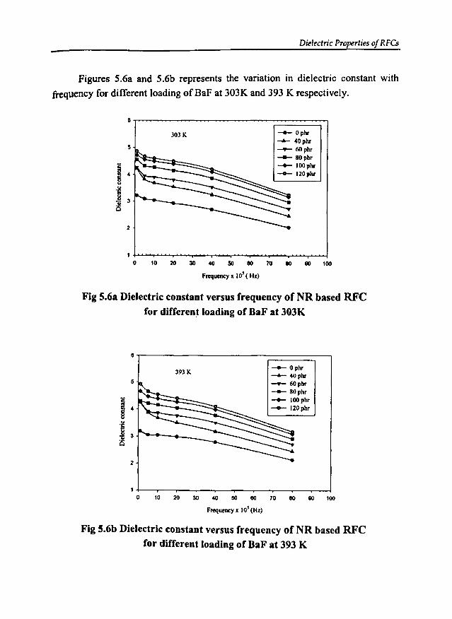
Dielectric Properties of RFCs
Figures 5.6a and 5.6b represents the variation in dielectric constant with
frequency for different loading ofBaF at 303K and 393 K respectively.
8
303K__ Ophr
""""- 40phr5 ~ 60phr
-- 80pbr
I 4
__ IOOphr
-- 120pbr<>
'6"il 3is
2
10 10 20 30 40 50 80 70 80 80 100
fmjucney x 10' ( Hz)
Fig 5.6a Dielectric constant versus frequency of NR based RFC
for different loading of naF at 303K
8
393 K -- Ophr~ 40phr
5 ~ 60phr
-- 80phr
I 4
__ IOOpbr__ J20phr
<>'§"il 3is
2
10 10 20 30 40 50 80 70 80 80 100
Fmjucncy x J0' (Hz)
Fig 5.6b Dielectric constant versus frequency of NR based RFC
for different loading of Baf' at 393 K
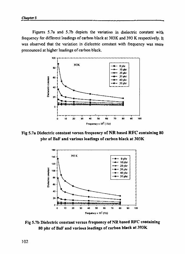
ChRpter5
Figures 5.7a and 5.7b depicts the variation in dielectric constant with
frequency for different loadings of carbon black at 303K and 393 K respectively. Itwas observed that the variation in dielectric constant with frequency was more
pronounced at higher loadings of carbon black.
100
80-+- Ophr-..- IOphr-.- 20phr
j 80 -- 30phr
~-+- 40phr
0 __ SOphruu 40os1!uis 20
0
o W 20 ~ ~ 00 80 ro 80 00 ~
Frequency x 10' (Hz)
Fig 5.7a Dielectric constant versus frequency ofNR based RFC containing 80
phr of BaF and various loadings of carbon black at 303K
160
140
120
8 100
§u eo'tiu eoCl
40
20
00
393 K-+- Ophr-..- IOphr-.- 20phr
-- 30phr__ 40phr
- SOphr
W 20 ~ ~ 60 80 ro eo 00 ~
Frequency x 10' (Hz)
Fig 5.7b Dielectric constant versus frequency ofNR based RFC containing80 phr of BaF and various loadings of carbon black at 393K
102
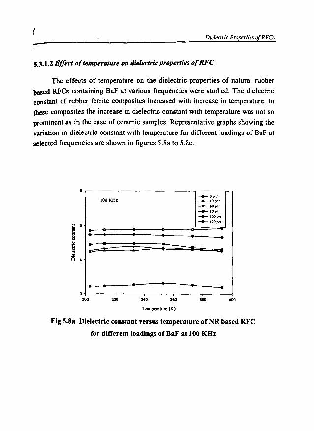
Dielectric Properties of RFCs-5.3.1.2 Effect oftemperature on dielectric properties ofRFC
The effects of temperature on the dielectric properties of natural rubber
based RFCs containing BaF at various frequencies were studied. The dielectric
constant of rubber ferrite composites increased with increase in temperature. Inthese composites the increase in dielectric constant with temperature was not so
prominent as in the case of ceramic samples. Representative graphs showing the
variation in dielectric constant with temperature for different loadings of BaF at
selected frequencies are shown in figures 5.8a to 5.8c.
__ Ophr
100KHz -- ~Oph,......- 60 ph,__ 80"",
......... IOOph'__ 120ph,
• • • • • •;; : : : -. •
• • • •• •
8
3
300 320 340 360 400
Temperature (K)
Fig 5.8a Dielectric constant versus temperature of NR based RFC
for different loadings of BaF at 100 KHz
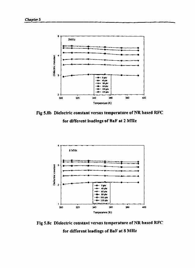
Chapter 5
2MHz
: : : : : :• • • • • •" " " , .. .... .. .. .. ... ..... -+- Opllr
........ 40plr__ 60phr
__ IOplv
-+- IOOpllr-0- 120pIv
j ~
.~;;is 3
2300 320 ~o
Temperature (K)
380
Fig 5.8b Dielectric constant versus temperature of NR based RFC
for different loadings -ofBaF at 2 MHz
8MHz
I • • • • I• • • • • •" " " " "
,... .. .. .. .. .... __ ophr
........ 40phr__ 60"'"__ IOphr
-+- lOOpllr-o-I20pllr
1300 320 ~o 380 380
Tempcnlture (K)
Fig 5.8c Dielectric constant versus temperature of NR based RFC
for different loadings of BaF at 8 MHz
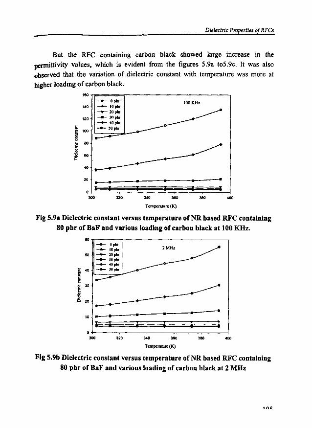
Dielectric Properties of RFCs-But the RFC containing carbon black showed large increase in the
permittivity values, which is evident from the figures 5.9a t05.9c. It was alsoobserved that the variation of dielectric constant with temperature was more at
higher loading ofcarbon black.
I••
100KHz
•
380
Temperature(K)
180
-- Ophr140 -- IOph.
-1'- 20 ph.
120__ JOph.__ 4Oph.
i 100 -- 50phr
u 80'Sj
~80
40
20 • ••I I I
0300 320 340
Fig 5.9a Dielectric constant versus temperature of NR based RFC containing80 phr of BaF and various loading of carbon black at 100 KIIz.
400380
•
80 -- Opllr--- 10 pIl.50
__ 20phr
__ 30"".__ 4OpIl,
-= 40 __ SO"".8;I0uu 30.~
0;is 20
• • •10 •I I i •0
300 320 340 380
Temperature(K)
Fig 5.9b Dielectric constant versus temperature of NR based RFC containing
80 phr of BaF and various loading of carbon black at 2 MHz
,ne.
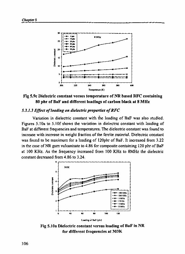
ChapterS
3Orr====;-------------.,__ 0'"__ 10 .....
25 __ 20pb<__ 30pIIr
~olOpIIr
)20 ~ lOpIIr
j 15
is 10
• • • • • ....
340320o+----~--_.__--_.__--""T'""""-____j
300
Tempo,,"'.e(K)
Fig 5.9c Dielectric constant versus temperature of NR based RFC containing80 phr of BaF and different loadings of carbon black at 8 MOz
5.3.1.3 Effect ofloading on dielectric properties ofRFC
Variation in dielectric constant with the loading of BaF was also studied.Figures 5.10a to S.IOf shows the variation in dielectric constant with loading ofBaF at different frequencies and temperatures. The dielectric constant was found toincrease with increase in weight fraction of the ferrite material. Dielectric constantwas found to be maximum for a loading of 120phr of BaF. It increased from 3.22in the case ofNR gum vulcanisate to 4.86 for composite containing 120 phr ofBaFat 100 KHz. As the frequency increased from 100 KHz to 8MHz the dielectricconstant decreased from 4.86 to 3.24.
)OlK
__ 100KHz
-...0.- $OOKH.__ ."'H.__ 2KH.__ 4MH.__ IMH.
120'0000401 t--......-----..---..----.----==::;:==~
o
LOIldinl of B.F (pb,)
Fig 5.10a Dielectric constant versus loading of BaF in NRfor different frequencies at 303K
106

- Dielectric Properties of RFCs
8r---------------------,313 K
5
2
o 20 40 80 80 lOO
lOllding of B.f (phr)
__ 100KHz
-- SooKHz___ I MHz__ 2MHz__ 4MHz__ 8MHz
120 140
Fig 5.10b Dielectric constant versus loading of BaF in NR
for different frequencles at 313K
8.,----------------------.333K
2
o 20 40 60 80 100
__ 100KHz
-- 500K.Hz___ 1101Hz__ 2101Hz
........ 4101Hz__ 1101Hz
120 140
loadin. ofBaF (phr)
Fig 5.10c Dielectric constant versus loading of BaF in NR
for different frequencies at 333K
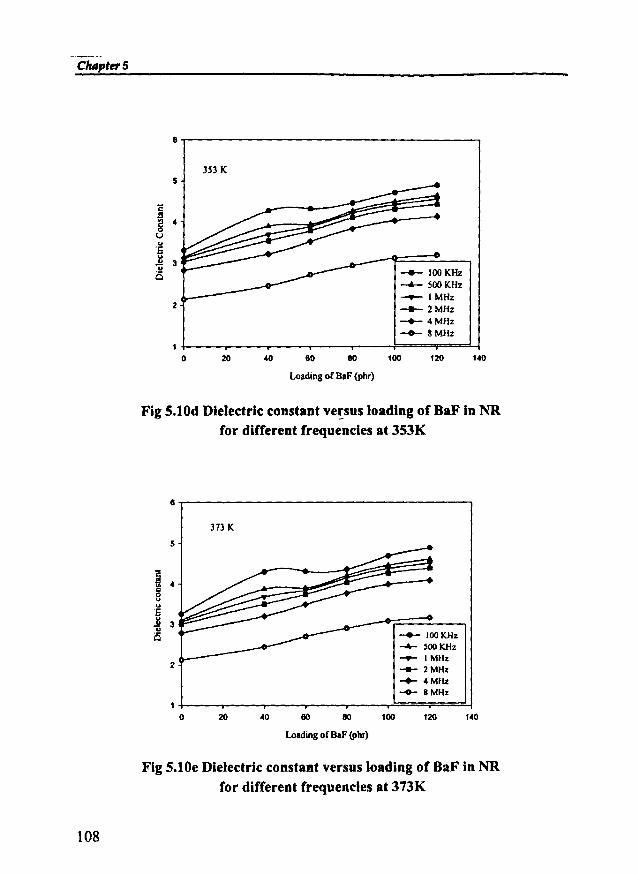
Clurpter5
6,..----------------------,
353 K5
2
-+- 100KHz-..- 500KHz___ I MHz__ 2MHz
-+- 4MHz__ 8MHz
o 20 40 80 80 100 120 140
Loadingof OaF(phr)
Fig 5.10d Dielectric constant ve!sus loading of BaF in NRfor different frequencies at 353K
6.,---------------------.,373 K
2
__ 100KHz
-4- ~ooKHz__ IMHz
...- 2MHz-+- 4MHz__ BMHz
40 80 80 100 120 140
108
LoadingofBaF (phr)
Fig 5.10e Dielectric constant versus loading of BaF in NRfor different frequencies at 373K
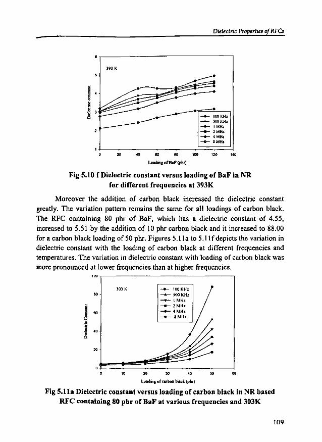
Dielectric Properties of RFCs-8
393 K
5
i 4
8.~
] J
~ -.- 100KHz-4- 500KHz-.- I MH.
2 ____ 2 MHz
-.- 4 MHz__ 8MHz
I0 20 40 eo eo 100 120 140
laldinll ofBaF (pIIr)
Fig 5.10 f Dielectric constant versus loading of BaF in NRfor different frequencies at 393K
Moreover the addition of carbon black increased the dielectric constantgreatly. The variation pattern remains the same for all loadings of carbon black.The RFC containing 80 phr of BaF, which has a dielectric constant of 4.55,increased to 5.51 by the addition of 10 phr carbon black and it increased to 88.00for a carbon black loading of 50 phr. Figures 5.11a to 5.11f depicts the variation indielectric constant with the loading of carbon black at different frequencies andtemperatures. The variation in dielectric constant with loading of carbon black wasmore pronounced at lower frequencies than at higher frequencies.
__ 100KHz
-- SooKHz____ l MHz__ 2MHz___ 4MHz___ 8 MHz
100
eo
i~ 1IO
U-,j 40.l!0
20
0
0
303 K
10 20 :lO 40 50
Loadinllofcllboa black (phr)
Fig 5.118 Dielectric constant versus loading of carbon black in NR basedRFC containing 80 pbr of BaF at various frequencies and 303K
109
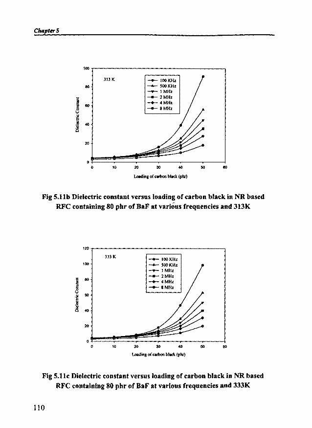
ChapterS
100
313 K -- 100KHz80 -4-- 500KHz
__ IMHz
j -- 2MHz-+- 4MHzg 80-- 8MHzu
u·S
~ .0
is
20
00 10 20 30 .0 50 80
u.dins of carbonblack (piu)
Fig S.llb Dielectric constant versus loading of carbon black in NR basedRFC containing 80 phr of naF at various frequencies and 313K
120
333 K-- 100KHz
100 -4-- 500KHz__ IMHz
§__ 2MHz
80 -+- 4MHz~ -- SMHz0ou 80·S11..is .0
20
00 10 20 30 .0 50 80
u.dins of carbonblack (phr)
Fig S.llc Dielectric constant versus loading of carbon black in NR basedRFC containing 80 phr of naF at various frequencies and 333K
110

- Dielectric Properties of RFCs
120
353 K -- 100KHz100 --- SooKHz
____ I MHz
8-- 2MHzeo __ 4MHz
~ -- 8MHzu eo"fiuis 40
20
00 10 20 30 40 50 eo
Lo.ding of cubon black (phr)
Fig 5.11d Dielectric constant versus loading of carbon black in NR basedRFC containing 80 phr of BaF at various frequencies and 353K
140
-- 100KHz120 373 K --- 500KHz____ I MHz
100 __ 2MHz
8 __ 4MHz
~ 80 -- 8MHzuu.~ eo~
40
20
00 10 20 30 40 50 eo
Loadingof carbonblack (phr)
Fig 5.11e Dielectric constant versus loading of carbon black in NR basedRFC containing 80 phr of BaF at various frequencies and 373K
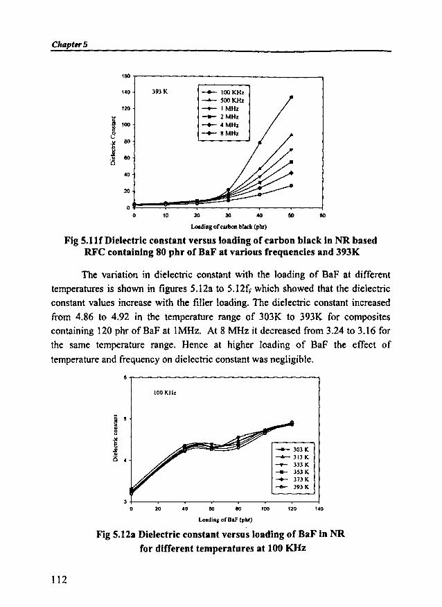
ChapterS
180 .----------- ---,
140
120
j lOO
~'S 80
~is 80
40
20
393 K
10 20
-- 100KHz-- 500KHz___ I MHz__ 2MHz__ 4MHz
-- 8MHz
30 40 50 80
Loadingof carbonblack (pIli")
Fig 5.11( Dielectric constant versus loading of carbon black in NR basedRFC containing 80 phr of BaF at various frequencies and 393K
The variation in dielectric constant with the loading of BaF at different
temperatures is shown in figures 5.12a to 5.12f, which showed that the dielectricconstant values increase with the filler loading. The dielectric constant increased
from 4.86 to 4.92 in the temperature range of 303K to 393K for compositescontaining 120 phr of BaF at IMHz. At 8 MHz it decreased from 3.24 to 3.16 forthe same temperature range. Hence at higher loading of BaF the effect of
temperature and frequency on dielectric constant was negligible.
&..---------------------,100 KH.
-- 303K--- 313 K___ 333 K
__ 353 K__ 373 K
......... 393 K
140120100&04020J+---,---.---~-~--......_-___._----l
o
Lo.dins ofBal' (ph.)
Fig 5.12a Dielectric constant versus loading of BaF in NRfor different temperatures at 100 KHz
112

Dielectric Properties of RFCs
8-r-------------------,
500 KHz
-- 303K--..- 313 K___ 333K__ 353K
--+- 373K__ 393K
20 40 80 80 100 120 140
Loading of BaF(phr)
Fig 5.12b Dielectric constant versus loading of BaF in NRfor different temperatures at 500 KHz
5..----------------------,
20 40
--+- 303 K'-"-JI3K__ 333K
--- 353 K--+- 373 K
-- 393K
80 80 100 120 140
Loading of BaF(phr)
Fig S.12c Dielectric constant versus loading of BaF in NRfor different temperatures at 1 MHz
113
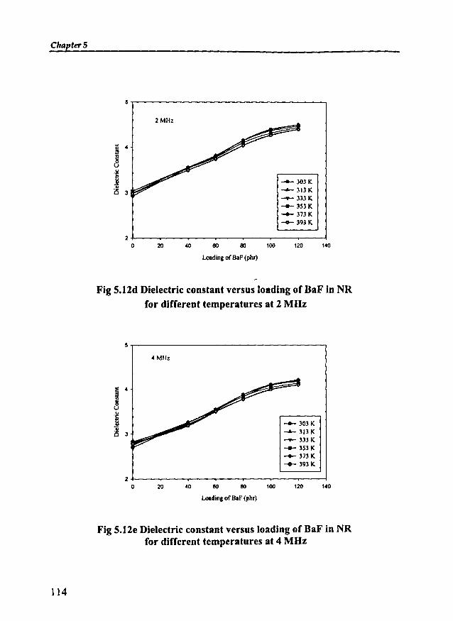
Chapter 5
2 MHz
;; 4l!
~...'S
~ -- 303 K
is 3 -- 313 K__ 333K
---- 353 K-+- 373 K
-- 393K
20 20 40 80 80 100 120 140
Loading of BaF(phr)
Fig 5.12d Dielectric constant versus loading of BaF in NRfor different temperatures at 2 MHz
5-r--------------------,4 MHz
20 40
-- 303K--313K__ 333K
...... 353K-+- 373 K...... 393K
60 80 100 120 140
Loadingof B.F (phr)
114
Fig S.12e Dielectric constant versus loading of BaF in NRfor different temperatures at 4 MHz
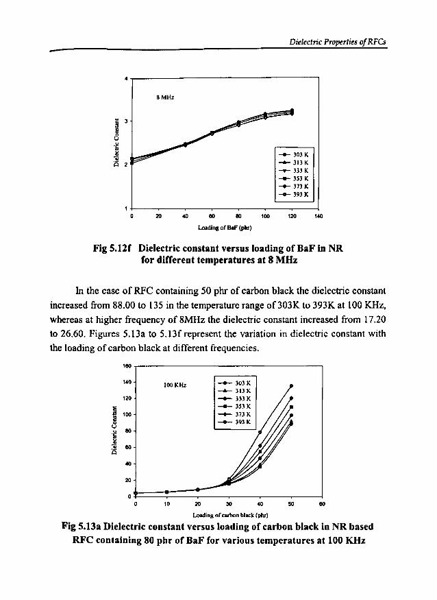
Dielectric Properties of RFCs-4..-------------------,
SMHz
-- 303K........ 313K__ 333 K
---- 3S3 K__ 373K__ 393K
20 40 80 80 100 120 140
Loading of OaF (phr)
Fig 5.l2f Dielectric constant versus loading of BaF in NRfor different temperatures at 8 MHz
In the case of RFC containing 50 phr of carbon black the dielectric constant
increased from 88.00 to 135 in the temperature range of303K to 393K at 100 KHz,
whereas at higher frequency of 8MHz the dielectric constant increased from 17.20
to 26.60. Figures 5.13a to 5.13frepresent the variation in dielectric constant with
the loading of carbon black at different frequencies.
100 KHz -- 303 K-- 313K__ 333K
-- 3S3K__ 373K__ 393K
180
140
120
fj 100a0uu 80.~
'ii 80C
40
20
00 10 20 30 40 50 80
Loadinll of carbon black (phr)
Fig 5.13a Dielectric constant versus loading of carbon black in NR basedRFC containing 80 pbr ofBaF for various temperatures at 100 KHz
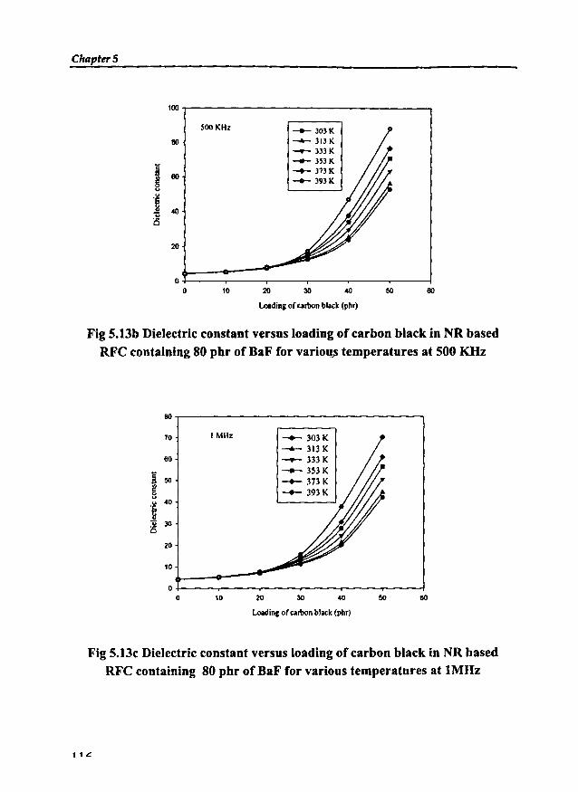
ChRpter5
100
500 KHz --+- 303K80 -- 313K
-.- 333K
a__ 3HK
60--+-313K
g --+-3931(..'fi .a1lis
20
00 10 20 30 .a 50 80
LoIdingor carbonblack(phr)
Fig 5.13b Dielectric constant versus loading of carbon black in NR basedRFC containing 80 pbr of BaF for vario~ temperatures at 500 KHz
I MHz -+- 303 K--....- 313 K__ 333K
-- 353K-- 373K-+- 393 K
80
70
60
~ 50
§.~
40
1l 30is
20
10
00 10 20 30 40
loading of carbonblack(phr)
50 80
Fig 5.13c Dielectric constant versus loading of carbon black in NR basedRFC containing 80 pbr of BaF for various temperatures at IMHz
1 1 I:.
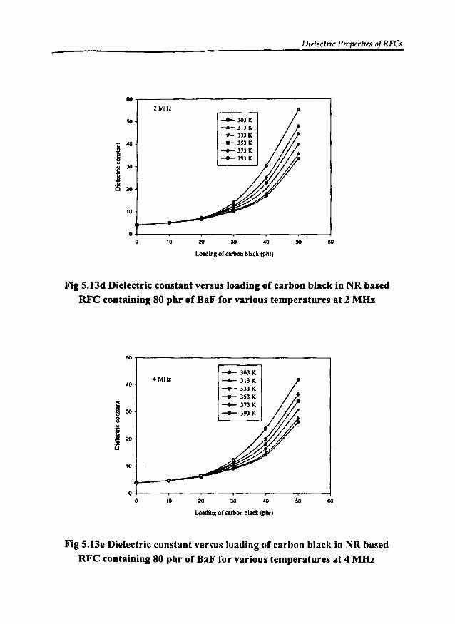
- Dielectric Properties of RFCs
110
2 MH~
50__ 303K
-4- 313 K-.- H3K
~40
___ 3S3K__ 373K
a __ 393 K0u
'S 30
~is 20
10
00 10 20 30 .0 50 110
lolldinll ofcubon black (phr)
Fig 5.13d Dielectric constant versus loading of carbon black in NR basedRFC containing 80 phr of BaF for various temperatures at 2 MIIz
50
--4- 303K4MHz ......... 313 K.0
..........- 333 K
......... 3S3K
I ~373K
30 --+- 393 K
,~20
~
10
00 10 20 30 .0 110
Loading ofcubon black (phr)
Fig S.13e Dielectric constant versus loading of carbon black in NR basedRFC containing 80 pbr of BaF for various temperatures at 4 MIIz
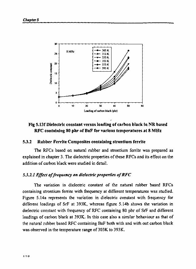
Chapter 5
30
8MHz -- 303K25 -- 313K
__ 333K
-- 3S3K
I20 __ 373K
-- 393K
.~15
~is 10
5
00 10 20 30 40 50 60
Loadingof carbonblack(phr)
Fig S.13f Dielectric constant versus loading of carbon black in NR basedRFC containing 80 phr of BaF for various temperatures at 8 MHz
5.3.2 Rubber Ferrite Composites containing strontium ferrite
The RFCs based on natural rubber and strontium ferrite was prepared as
explained in chapter 3. The dielectric properties of these RFCs and its effect on the
addition ofcarbon black were studied in detail.
5.3.2.1 Effect offrequency on dielectric properties ofRFC
The variation in dielectric constant of the natural rubber based RFCs
containing strontium ferrite with frequency at different temperatures was studied.
Figure 5.14a represents the variation in dielectric constant with frequency for
different loadings of SrF at 393K, whereas figure 5.14b shows the variation in
dielectric constant with frequency of RFC containing 80 phr of SrF and different
loadings of carbon black at 393K. In this case also a similar behaviour as that of
the natural rubber based RFC containing BaF both with and with out carbon black
was observed in the temperature range of 303K to 393K.
110
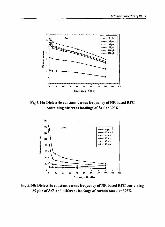
Dielectric Properties of RFCs
11
393 K -- Ophr8
~ 40phr.....- 60phr
-- 80phr
~__ l00phr
8 __ 120phra0uu 5'~
~ 4
3
2
0 10 20 30 40 50 80 10 80 110 100
Frequency ~ 10' (Hz)
Fig 5.14a Dielectric constant versus frequency ofNR based RFCcontaining different loadings of SrF at 393K
180
140
120
I 100
uu eo'6],li 600
40
20
00
393 K __ Ophr
~ 10phr
-- 20phr-- 30phr__ 40phr
-- 50phr
10 20 30 40 50 80 10 80 90 100
Frequency x 10' (Hz)
Fig 5.14b Dielectric constant versus frequency of NR based RFC containing80 phr of SrF and different loadings of carbon black at 393K.
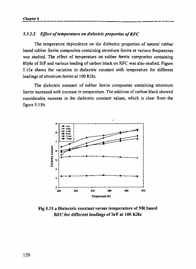
ClrapterS
5.3.2.2 Effect oftemperature on dielectricproperties ofRFC
The temperature dependence on the dielectric properties of natural rubber
based rubber ferrite composites containing strontium ferrite at various frequencies
was studied. The effect of temperature on rubber ferrite composites containing
80phr of SrF and various loading of carbon black on RFC was also studied. Figure
5.l5a shows the variation in dielectric constant with temperature for different
loadings of strontium ferrite at 100 KHz.
The dielectric constant of rubber ferrite composites containing strontium
ferrite increased with increase in temperature. The addition of carbon black showed
considerable increase in the dielectric constant values, which is clear from the
figure 5.1Sb.
9"lf""""""--~-------------""
....
..•••• •4
3
8
7~'----~
400380340320
2 +-----r---,...-----,-----,,..-----j
300
T~ture(K)
Fig 5.15 a Dielectric constant versus temperature of NR basedRFC for different loadings of SrF at 100 KHz
120
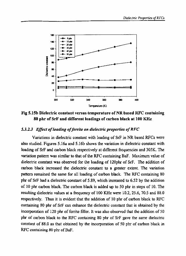
Dielectric Properties of RFCs
1eo
140
120
i100
eo
"i eo
! 40
20
I I I • • I0
300 320 340 360 3lIO
T~(K)
Fig S.lSb Dielectric constant versus temperature of NR based RFC containing80 phr of SrF and different loadings of carbon black at 100 KHz
5.3.2.3 Effect ofloading offerrite on dielectric properties ofRFC
Variations in dielectric constant with loading of SrF in NR based RFCs were
also studied. Figures 5.16a and 5.16b shows the variation in dielectric constant with
loading of SrF and carbon black respectively at different frequencies and 303K. The
variation pattern was similar to that of the RFC containing BaF. Maximum value of
dielectric constant was observed for the loading of 120phr of SrF. The addition of
carbon black increased the dielectric constant to a greater extent The variation
pattern remained the same for all loading of carbon black. The RFC containing 80
phr of SrF had a dielectric constant of 5.89, which increased to 6.52 by the addition
of 10 phr carbon black. The carbon black is added up to 50 phr in steps of 10. The
resulting dielectric values at a frequency of lOO KHz were 10.2,25.6, 70.5 and 88.0
respectively. Thus it is evident that the addition of 10 phr of carbon black to RFC
containing 80 phr of SrF can enhance the dielectric constant that is obtained by the
incorporation of 120 phr of ferrite filler. It was also observed that the addition of 50
phr of carbon black to the RFC containing 80 phr of SrF gave the same dielectric
constant of 88.0 as that obtained by the incorporation of 50 phr of carbon black in
RFC containing 80 phr ofBaF.
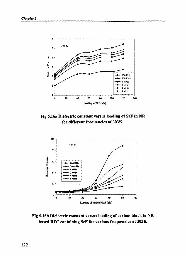
ChApterS
Fig 5.16a Dielectric constant versus loading of SrF in NRfor different frequencies at JOJK.
100
303 K
80
ig 80 __ 100KHzU
--- 500KHz"'6 -..- I MHz
~ 40__ 2MHz
'0 __ .cMHz__ 8MHz
20
00 10 20 30 40 50 80
loadina ofcllbon black (phr)
Fig 5.16b Dielectric constant versus loading of carbon black in NRbased RFC containing SrF for various frequencies at JOJK
122
- Dielectric Properties of RFCs
The variation in dielectric constant with the loading ofSrF and carbon black at
different temperatures indicated that the permittivity values increased with the filler
loading. The dielectric constant increased from 6.45 at 303K to 8.22 at 393K for 120
phr loading of SrF at a frequency of 100 KHz. At 8 MHz the value increased from
3.71 to 4.62. The dielectric constant increased from 88.00 at 303K to 135 at 393K
with the addition of SO phr carbon black to RFC containing 80 phr of SrF at 100
KHz, whereas at a frequency of 8MHz the value increased from 17.7 to 19.60.
5.4 DIELECTRIC STUDIES OF NITRILE RUBBER BASED RUBBERFERRITE COMPOSITES
The dielectric properties of nitrile rubber based RFCs were carried out at
different frequencies and temperatures. The effect ofdielectric constant on various
parameters such as frequency, temperature and loading of ferrite fillers and carbonblack were studied.
5.4.1 Nitrile rubber based RFCs containing barium ferrite
The rubber ferrite composites containing BaF in NBR was prepared as
explained in chapter 3. The effect of the incorporation of carbon black on the
dielectric properties of RFes was also studied in detail.
5.4.1.1 Frequency dependence on dielectric constant ofRFCs
The dielectric behaViour ofNBR based RFCs containing BaF with change in
frequency at different temperatures was studied. Figure 5.17a represent the
variation in dielectric constant with frequency for different loadings of BaF in NBR
at 393K. The absolute values of the dielectric constant of the composites were
found to be greater than that of the gum NBR vulcanisates but less than that of the
ceramic component. The dielectric constant decreased with increasing frequency
for composites containing different loadings of BaF, which is in accordance with
the Maxwell Wagner theory of interfacial polarization. Almost a similar behaviour
as that of the RFCs containing BaF in NR was obtained in this case also.
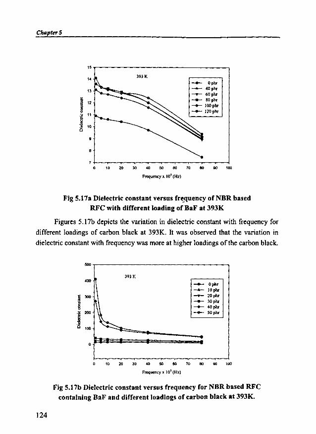
ChapterS
15,------------------,14
13
9
8
393K
-- Opllr-- 40phr........- 60phr--+- 80phr__ IOOpllr
__ 120pllr
1+-~--r--.,.____.,..___._-_r_-.____._-"""T'"""__l
o ID 20 30 4D 50 80 10 80 BD 100
Frequency x 10' (Hz)
Fig 5.17a Dielectric constant versus frequency of NBR basedRFC with different loading of BaF at 393K
Figures 5.17b depicts the variation in dielectric constant with frequency for
different loadings of carbon black at 393K. It was observed that the variation in
dielectric constant with frequency was more at higher loadings of the carbon black.
50D
393K400
I 300
s'! 200
~uQ 100
0
__ Ophr
-- IOpllr........- 20pllr--+- 30phr__ 40pllr__ SOpht
.....
o m 20 30 ~ 50 80 ro 80 9D ~
Frequency x 10' (Hz)
Fig 5.17b Dielectric constant versus frequency for NBR based RFCcontaining BaF and different loadings of carbon black at 393K.
124
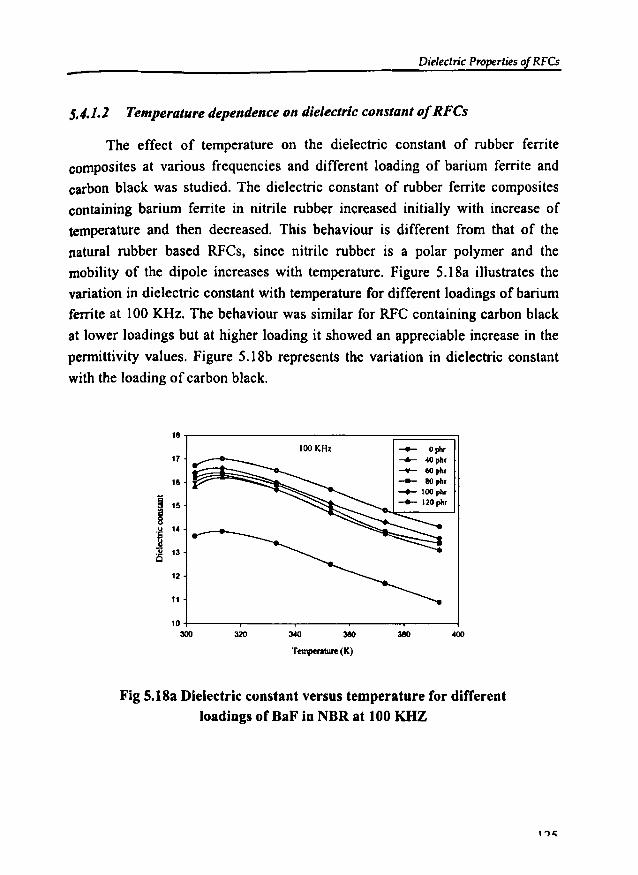
Dielectric Properties of RFCs
5.4.1.2 Temperature dependence on dielectric constant ofRFCs
The effect of temperature on the dielectric constant of rubber ferrite
composites at various frequencies and different loading of barium ferrite and
carbon black was studied. The dielectric constant of rubber ferrite composites
containing barium ferrite in nitrile rubber increased initially with increase of
temperature and then decreased. This behaviour is different from that of the
natural rubber based RFCs. since nitrile rubber is a polar polymer and the
mobility of the dipole increases with temperature. Figure 5.18a illustrates the
variation in dielectric constant with temperature for different loadings of barium
ferrite at 100 KHz. The behaviour was similar for RFC containing carbon black
at lower loadings but at higher loading it showed an appreciable increase in the
permittivity values. Figure 5.l8b represents the variation in dielectric constant
with the loading ofcarbon black.
18
17
18
j 15gu
"S I.Jl., 13is
12
11
10300 320 380
Tempentl1re (K)
Fig 5.18a Dielectric constant versus temperature for differentloadlngs of BaF In NBR at 100 KHZ

ChapterS
100KHz
400
i3eO
Temperalllre (K)
!lOO
4SO -- ophr.......- 10 phr
400 ___ 20phr
3SO__ 30phr
i__ 40phr
300__ SOphr
§o~
2SO
~200
ISO
100
SO
I I i0
300 320 340
Fig 5.l8b Dlelectrle constant versus temperature of NBR based RFCscontaining BaF and different loadlngs of carbon black at 100 KHZ
5.4.1.3 Dependence ofBaF loading on dielectric constant ofRFCs
Variations in dielectric constant with the loading of barium ferrite andcarbon black were also studied. Figure 5.19a shows the variation in dielectricconstant with loading of BaF at different frequencies. The dielectric constant wasfound to increase with the addition of the ferrite filler. As expected the maximumvalue of dielectric constant was observed for a loading of 120phr of BaF.Dielectric constant increased from 13.7 for NBR gum vulcanisate to 16.7 with 120phr of BaF at 303K and a frequency of 100 KHz.
__ 100KHz 303 K
-+- SooKHz__ IMHz__ 2MHz__ 4MHz
-- .MHz
.----...-..-- -A...-
~
....
30
28
28
2422
I ~:IS 18
01 14
- 12is 10
8
8
42
oo 20 40 eo 80 100 120
Loading of BaF (phr)
Fig 5.19a Dielectrlc constant versus loading of BaF in NBRfor different frequencies at 303K
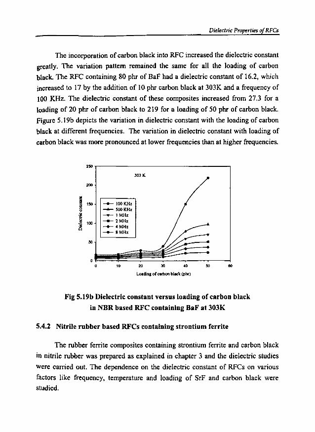
Dielectric Properties of RFCs
The incorporation of carbon black into RFC increased the dielectric constant
greatly. The variation pattern remained the same for all the loading of carbon
black. The RFC containing 80 phr of BaF had a dielectric constant of 16.2, which
increased to 17 by the addition of 10 phr carbon black at 303K and a frequency of
100 KHz. The dielectric constant of these composites increased from 27.3 for a
loading of 20 phr of carbon black to 219 for a loading of 50 phr of carbon black.
Figure 5.19b depicts the variation in dielectric constant with the loading of carbon
black at different frequencies. The variation in dielectric constant with loading of
carbon black was more pronounced at lower frequencies than at higher frequencies.
250
303 K
200
~il 150 -+- 100KHzu -- 500KHz
'S -.- 1 MHzl:l 100 --- 2 MHzUis -+- 4 MHz
-+-IMHz
50
00 10 20 30 40 50 eo
Loadinsof carboo bIllet (phf)
Fig 5.19b Dielectric constant versus loading of carbon black
in NBR based RFC containing BaF at 303K
5.4.2 Nitrile rubber based RFCs containing strontium ferrite
The rubber ferrite composites containing strontium ferrite and carbon black
in nitrile rubber was prepared as explained in chapter 3 and the dielectric studies
were carried out. The dependence on the dielectric constant of RFCs on various
factors like frequency, temperature and loading of SrF and carbon black were
studied.

ChapterS
5.4.2.1 Frequency dependence on dielectric constant ofRFCs
The variation in dielectric constant of NBR based RFCs containing
strontium ferrite with frequency at different temperatures was studied. It can be
seen that the dielectric constant decreased with frequency for different loadings of
SrF. The absolute values of the dielectric constant of the composites were found to
be in between that of the gum NBR vulcanisate and the ceramic SrF. Figure 5.20a
represent the variation in dielectric constant with frequency for different loadings
of strontium ferrite at 393 K. This behaviour was similar to that of the NBR based
RFCs containing BaF.
18~----------------,
16
8
393K __ Ophr
-- 40phr-.- 60phr__ 80phr
___ lOOphr
__ 120pbr
1008040 80
Frequencp 10' (Hz)
208..----.-----..---.----....-----4
o
Fig 5.20a Dielectric constant versus frequency for various
loadings of SrF In NBR at 393K.
Figure 5.20b represent the variation in dielectric constant with frequency for
different loadings of SrF at 393K. For higher loadings of SrF the decrease in
dielectric constant was more pronounced at lower frequency range than at higher
frequency range.
128
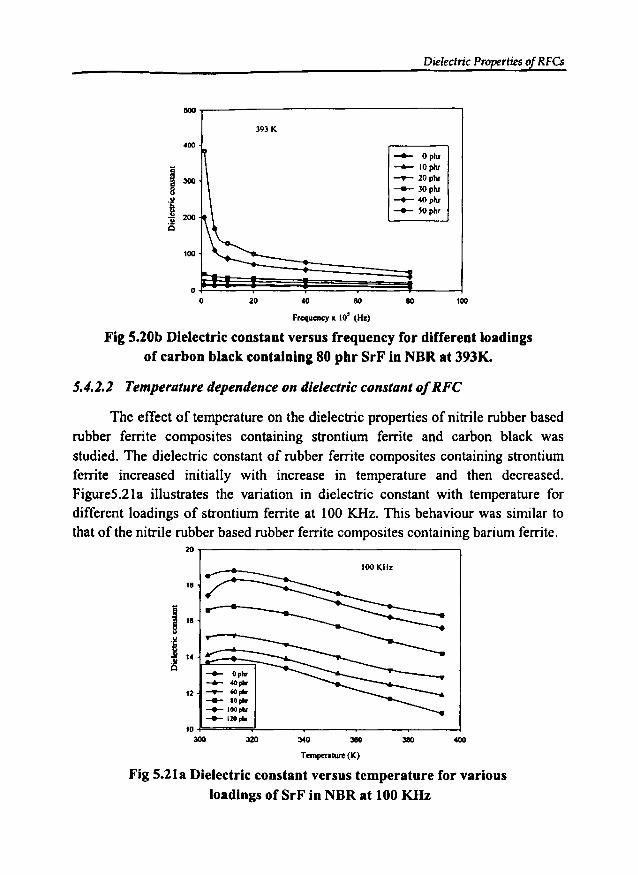
Dielectric Properties of RFCs
393 K
!lOO
400
I 300
j200
.1/Cl
100
00 20 40 eo
Frequency ~ 10' (Hz)
-- Oplu-- 10phr__ 20 piu___ 30 piu__ 40 piu__ SOphr
eo 100
Fig 5.20b Dielectric constant versus frequency for different loadingsof carbon black containing 80 phr SrF in NBR at 393K.
5.4.2.2 Temperature dependence on dielectric constant ofRFC
The effect of temperature on the dielectric properties of nitrile rubber basedrubber ferrite composites containing strontium ferrite and carbon black wasstudied. The dielectric constant of rubber ferrite composites containing strontiumferrite increased initially with increase in temperature and then decreased.Figure5.21a illustrates the variation in dielectric constant with temperature fordifferent loadings of strontium ferrite at 100 KHz. This behaviour was similar tothat of the nitrile rubber based rubber ferrite composites containing barium ferrite.
20..-------------------,
18
__ Gphr
-..... oIOpIor12 __ 60""
__ 10plor__ IOOplor
__ 120....
40038034032010 F==",.L------.------,,----....----l
300
Temper.cure (K)
Fig 5.21a Dielectric constant versus temperature for variousloadings of SrF in NBR at 100 KHz

CIulpttT5
The addition of carbon black caused appreciable increase in the dielectric
constant. Figure 5.21b represents the variation in dielectric constant with
temperature for various loading of carbon black. It was observed that the increase
in dielectric constant with temperature was more at higher loadings of the carbon
black.
400
350
300
B 250
§.. 200"§U 150is
100
50
0300
100KHz
•I
320
•1
•1
380
TemperalUre (K)
-- Ophr--- IOphr___ 20phr__ 30phr
-+- 40phr-- ~Ophr
•I
380
•I
400
Fig S.21b Dielectric constant versus temperature for NBR based RFCs
containing 80 phr SrF and various Joadings of carbon black.
5.4.2.3 Dependence ofSrF loading on dielectric constant ofRFC
Studies on the variation in dielectric constant with the addition of strontium
ferrite were also carried out. It was observed that the dielectric constant increases
with increase of volume fraction of the ferrite material. Dielectric constant was
maximum for a loading of l20phr of strontium ferrite. At 303K the dielectric
constant of the nitrile rubber gum vulcanisate increased from 13.7 to 18.5 for a
loading of 120 phr of SrF at 100 KHz. The dielectric constant of these rubber
ferrite composites decreased as the frequency increases. Figure 5.22a shows the
variation in dielectric constant with loading of strontium ferrite for different
frequencies at 303K.
130
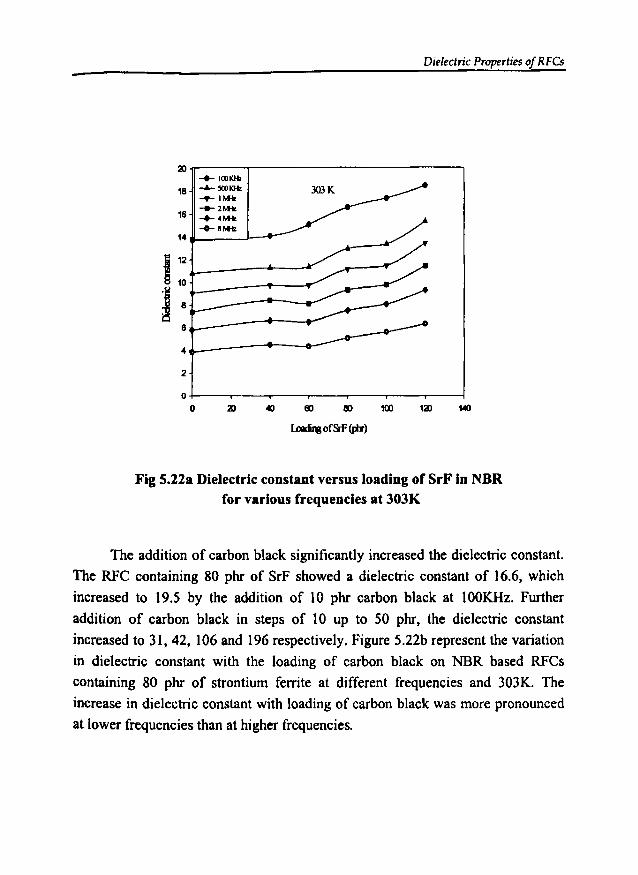
Dielectric Properties of RFCs-
21.....---....,--------------,...... 100KHz
18 ~5(l)KHz
-<r- I""'__ 2Mk
16 -+- 4Mk
-+- BMk14 ......__J--.--
112 L----.---..
f8 1- - - - -+----- -.-4L_---o----4~
2
14012110040o +-----.--........,.--,------.--........,.--,---~
o
Fig 5.22a Dielectric constant versus loading of SrF in NBRfor various frequencies at 303K
The addition of carbon black significantly increased the dielectric constant.
The RFC containing 80 phr of SrF showed a dielectric constant of t6.6, which
increased to 19.5 by the addition of 10 phr carbon black at 100KHz. Further
addition of carbon black in steps of 10 up to 50 phr, the dielectric constant
increased to 31, 42, 106 and 196 respectively. Figure 5.22b represent the variation
in dielectric constant with the loading of carbon black on NBR based RFCs
containing 80 phr of strontium ferrite at different frequencies and 303K. The
increase in dielectric constant with loading of carbon black was more pronounced
at lower frequencies than at higher frequencies.
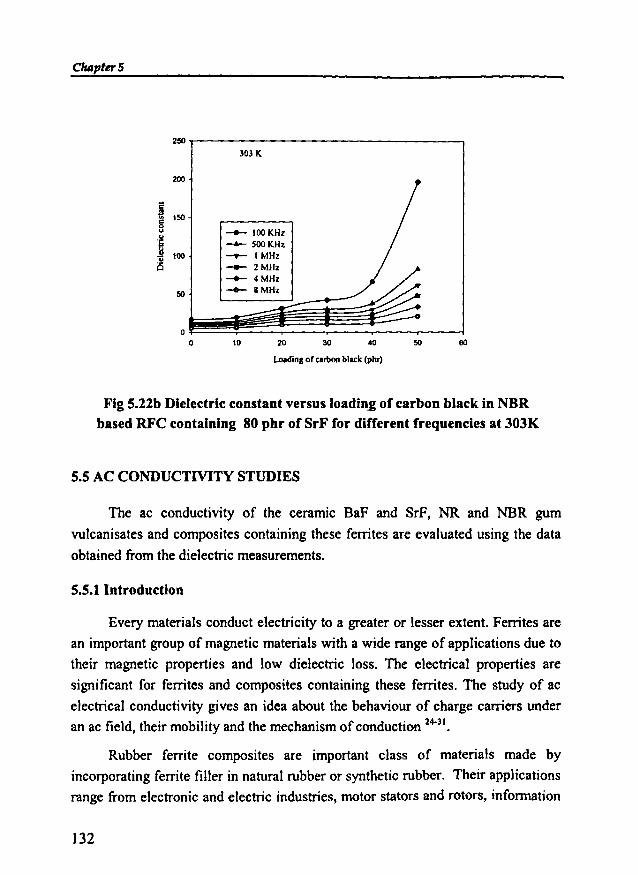
C1uI1'ter5
2SO
303 K
200
j150g... __ 100KHz...
"ti -A- 500KHz.. 100 -..- I MHzis __ 2MHz
~ 4MHz
SO --- 8MHz
00 10 20 30 .0 50 60
Loadingor carbonblack (piu")
Fig 5.22b Dielectric constant versus loadin-i of carbon black in NBRbased RFC containing 80 phr of SrF for different frequencies at 303K
5.5 AC CONDUCTIVITY STUDIES
The ac conductivity of the ceramic BaF and SrF, NR and NBR gum
vulcanisates and composites containing these ferrites are evaluated using the data
obtained from the dielectric measurements.
5.5.1 Introduction
Every materials conduct electricity to a greater or lesser extent. Ferrites are
an important group of magnetic materials with a wide range of applications due to
their magnetic properties and low dielectric loss. The electrical properties are
significant for ferrites and composites containing these ferrites. The study of ac
electrical conductivity gives an idea about the behaviour of charge carriers underan ac field, their mobility and the mechanism of conduction 24-31.
Rubber ferrite composites are important class of materials made by
incorporating ferrite filler in natural rubber or synthetic rubber. Their applications
range from electronic and electric industries, motor stators and rotors, information
132

Dielectric Properties ofRFCs
technology, printing and decoration. The size, shape and magnetisation pattern can
be designed according to user's need. Though literature on the ac conductivity of
ceramic ferrite fillers exists, data on rubber ferrite composites are rather scarce.
RFCs are essentially dielectric materials and their electrical properties are very
important from the application point of view. Hence studies on ac conductivity on
RFC and the correlation with that of the corresponding fillers assumes significance.
It was reported that the electron hopping between Fe2+ and Fe3+ is
responsible for conduction in ferrites. The conductivity studies on ferrites carried
out by various researchers proved its semiconducting behaviour and also proved
the dependence of electrical conductivity on preparation condition, sintering time,
temperature and the types of impurities 32.37.
The evaluation of ac electrical conductivity of ceramic BaF and SrF, NR and
NBRgum vulcanisate, as well as the rubber ferrite composites was calculated using
the data obtained from the dielectric measurements as explained in chapter 2.
Their dielectric constant and dielectric loss were evaluated by parallel plate
capacitor method by using a dielectric cell and an Impedance analyzer (HP
4285A). The acquisition of tanf values from dielectric permittivity measurements
and subsequent evaluation of ac conductivity have been made automatic.
From the dielectric loss and dielectric constant, ac conductivity of these
samples were evaluated using the relation
crac = 21tf tanf Eo Er (5.3)
where f is the frequency of the applied field, Eo is the absolute permittivity, Er
is the relative permittivity and tano is the loss factor.
AC conductivity of the ceramic samples, NR and NBR gum vulcanisates and
RFCs were evaluated in the frequency range from 100KHz to 8MHz. The
measurements were done at different temperatures of 303, 313, 333, 353,373 and
393K. The RFCs studied were based on NR containing various loading of SrF and
carbon black.
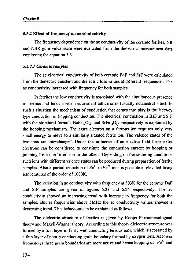
ChapterS
5.5.2 Effed of frequency on ac conductivity
The frequency dependence on the ac conductivity of the ceramic ferrites, NR
and NBR gum vulcanisate were evaluated from the dielectric measurement data
employing the equation 5.3.
5.5.2.1 Ceramic samples
The ac electrical conductivity of both ceramic BaF and SrF were calculated
from the dielectric constant and dielectric loss values at different frequencies. The
ac conductivity increased with frequency for both samples.
In ferrites the low conductivity is associated with the simultaneous presence
of ferrous and ferric ions on equivalent lattice sites (usually octahedral sites). Insuch a situation the mechanism of conduction that comes into play is the Verwey
type conduction or hopping conduction. The electrical conduction in BaF and SrF
with the structural formula BaFelZOl9 and SrFel20lJ respectively is explained by
the hopping mechanism. The extra electron on a ferrous ion requires only very
small energy to move to a similarly situated ferric ion. The valence states of the
two ions are interchanged. Under the influence of an electric field these extra
electrons can be considered to constitute the conduction current by hopping or
jumping from one 'iron' ion to the other. Depending on the sintering conditions
such ions with different valence states can be produced during preparation of ferrite
samples. Also a partial reduction of Fe3+ to Fez
+ ions is possible at elevated firing
temperatures of the order of 1000K.
The variation in ac conductivity with frequency at 303K for the ceramic BaF
and SrF samples are given in figures 5.23 and 5.24 respectively. The ac
conductivity showed an increasing trend with increase in frequency for both the
samples. But at frequencies above 5MHz the ac conductivity values showed a
decreasing trend. This behaviour can be explained as follows.
The dielectric structure of ferrites is given by Koops Phenomenological
theory and Maxell-Wagner theory. According to this theory dielectric structure was
formed by a first layer of fairly well conducting ferrous ions, which is separated by
a thin layer of poorly conducting grain boundary formed by oxygen ions. At lower
frequencies these grain boundaries are more active and hence hopping of FeZ'" and
134
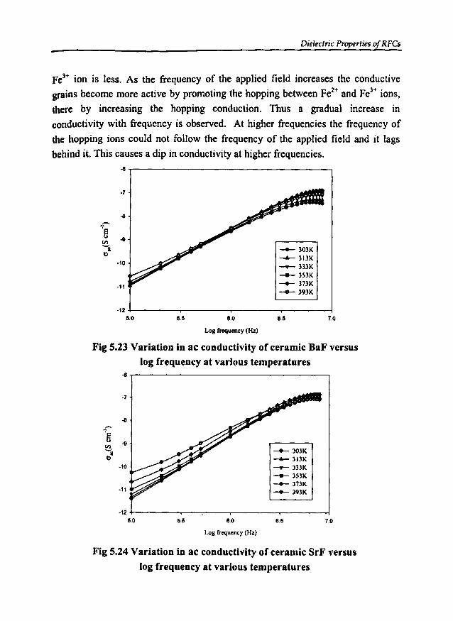
Dielectric Properties of RFCs
Fe3+ ion is less. As the frequency of the applied field increases the conductive
grains become more active by promoting the hopping between Fe2+ and Fe3+ ions,
there by increasing the hopping conduction. Thus a gradual increase in
conductivity with frequency is observed. At higher frequencies the frequency of
the hopping ions could not follow the frequency of the applied field and it lags
behind it. This causes a dip in conductivity at higher frequencies.-e
·7
...f"'e -ll
~ ___ 303Ktl .......- 313K
·10 ......... 333K
-- 3S3K-11
___ 373K
-Cl- 393K
-125.0 5.5 8.0 8.5 7.0
Loll frequency(Hz)
Fig 5.23 Variation in ac conductivity of ceramic BaF versus
log frequency at various temperatures-e
-7
-e-r--fi
-llCIl
~ -- 303K-..- 313K
-10 ~333K
-- 3S3K___ 373K-11 __ 393K
-125.0 6.5 60 6.6 7.0
Loll frequency (Hz)
Fig 5.24 Variation in ac conductivity of ceramic SrF versus
log frequency at various temperatures
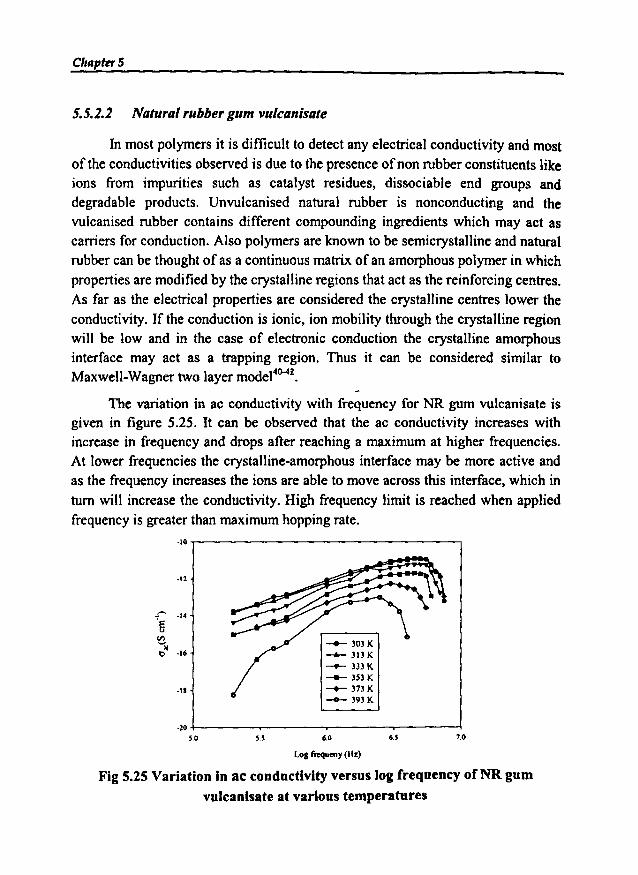
ChapterS
5.5.2.2 Natural rubbergum vulcanisate
In most polymers it is difficult to detect any electrical conductivity and mostof the conductivities observed is due to the presence ofnon rubber constituents likeions from impurities such as catalyst residues, dissociable end groups anddegradable products. Unvulcanised natural rubber is nonconducting and thevulcanised rubber contains different compounding ingredients which may act ascarriers for conduction. Also polymers are known to be semicrystalline and naturalrubber can be thought of as a continuous matrix of an amorphous polymer in whichproperties are modified by the crystalline regions that act as the reinforcing centres.As far as the electrical properties are considered the crystalline centres lower theconductivity. If the conduction is ionic, ion mobility through the crystalline regionwill be low and in the case of electronic conduction the crystalline amorphousinterface may act as a trapping region. Thus it can be considered similar toMaxwell-Wagner two layer model4
ll-4i .
The variation in ac conductivity with frequency for NR gum vulcanisate isgiven in figure 5.25. It can be observed that the ac conductivity increases withincrease in frequency and drops after reaching a maximum at higher frequencies.At lower frequencies the crystalline-amorphous interface may be more active andas the frequency increases the ions are able to move across this interface. which inturn will increase the conductivity. High frequency limit is reached when appliedfrequency is greater than maximum hopping rate.
-10
-12
.-. -14
fi~~
·16e
-11
-20
SO S.S
__ 303K
-..- 31) K-.- 333 K
-- 3S3K__ 373K__ 393K
6.0 6.S 7.0
LOll frcqucny (Hz)
Fig 5.25 Variation in ac conductivity versus log frequency of NR gumvulcanisate at various temperatures

Dielectric Properties of RFCs
5.5.2.3 Nitrile rubber gum vulcanisate
The ac conductivity of the NBR gum vu1canisate has been obtained from the
dielectric measurements. The variation in ac conductivity with frequency for NBR
gum vulcanisate is given in figure 5.26. It can be observed that the ac conductivity
increases with increase in frequency and drops after reaching a maximum at higher
frequencies, especially at high temperatures.
~
·7 -- 303K--...- 313 K
.a -.- 333 K
-- 3S3K
.g__ 373K
~
-- 393Ka ·10v.l
'lib -11
-12
-13
·1~
5.0 5.5 8.0 8.6 7.0
Log frequency (Hz)
Fig 5.26 Variation in ac conductivity versus log frequency ofNBR gumvulcanisate at various temperatures
5.5.3 AC conductivity studies of NR based rubber ferrite composites
Using the data obtained from the dielectric measurements, the ac conductivity
of the NR based RFCs containing 40,60,80,100 and 120 phr ofSrF were calculated.
The effect of carbon black on the ac conductivity of RFCs containing 80 phr of SrF
and 10, 20,30,40 and 50 phr of carbon black was also studied.
5.5.3.1 Frequency dependence on AC conductivity ofRFCs
The ac conductivity of the NR based RFC containing SrF was done at
different temperatures and frequencies. The RFCs also showed the same trend as
that of the ceramic ferrites. The figure 5.27 depicts a representative graph showing
the variation in ac conductivity versus log frequency of the RFCs.
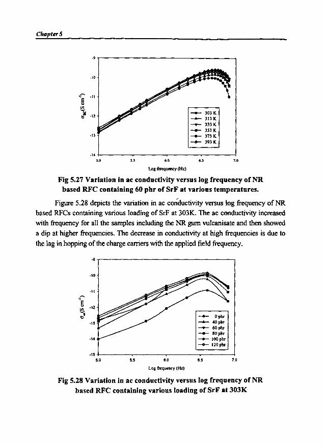
Chtlpter5
-9 r-------------------,
-10
·13
-- JOJK-- JI3K__ 333K
-- 3S3K-+- 371K
-- 393K
7.06.~60~.~
·14 ~---"'T'""""---_r_---~------l~.O
LoI fJRquency (Hz)
Fig 5.27 Variation in ae conductivity versus log frequency of NRbased RFC containing 60 phr of SrF at various temperatures.
Figure 5.28 depicts the variation in ac conductivity versus log frequency of NR
based RFCs containing various loading of SrF at 303K. The ac conductivity increased
with frequency for all the samples including the NR gum vulcanisate and then showed
a dip at higher frequencies. The decrease in conductivity at high frequencies is due to
the lag in hopping of the charge carriers with the applied field frequency.
·9
·10
-11
-rfi ·12(I)
..."Me -- Ophr
·13 -- 40phr__ 60pbr__ 80pbr
·14 -+- IOOphr__ 120pbr
·155.0 5.5 6.0 6.5 7.0
LoS frequency(Hz)
Fig 5.28 Variation in ac conductivity versus log frequency ofNRbased RFC containing various loading of SrF at 303K

Dielectric Properties of RFCs
Since the incorporation of carbon black is found to enhance the micro waveabsorbing properties, the NR based RFCs containing 80 phr of SrF and various
loading of carbon black were prepared and the ac conductivity was studied. Figure
5.29 shows the variation in ac conductivity of these RFCs with frequency for various
loading of carbon black. The ac conductivity increased with increasing frequency
and showed a slight dip at higher frequencies. More over the ac conductivities
increased with the loading of carbon black. This is because carbon black acts assemiconducting materials.
.. ..------------------,
-12
-.- Oplo~IOplr__ lOp.__ :lOplr
-.- 40plr-.- lOp•
11•14 +----------....-------===~-~
5
Fig 5.29 Variation in ac conductivity with log frequency of NR basedRFC containing 80 phr of SrF and various loading of carbon black.
5.5.3.2 Temperature dependence on AC conductivity ofRFCs
The temperature dependence on the NR based RFC containing 40,60, 80,
100 and 120 phr of SrF was evaluated at a frequency of IMHz. The figure 5.30
depicts a representative graph showing the variation in ac conductivity of RFCs
with temperature.
The ac conductivity of the RFCs showed a slight increase with increase in
temperature. This is due to increase in hopping between Fe2+ and Fe]+- ions at
higher temperatures. In the case of NR gum vulcanisate a decrease in conductivity
is noticed due to its nonconductive nature.
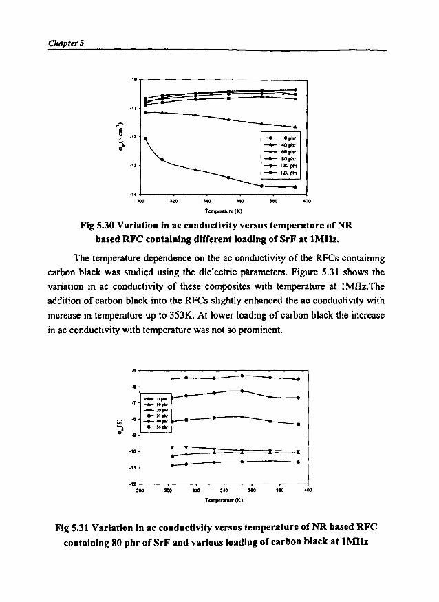
ChapterS
:140
.....__ Ophr
-...... 40pIu__ 60phr__ 10plu__ IOOplu
__ 120phr
I!
-----~--~·'0
12!== I·11 •
--"'e-'2f/l..
D
.'3
.,.:100 UO
Tcmperahl'" (K)
Fig 5.30 Variation in ae conductivity versus temperature ofNRbased RFC containing different loading of SrF at 1MHz.
The temperature dependence on the ac conductivity of the RFCs containing
carbon black was studied using the dielectric parameters. Figure 5.31 shows the
variation in ac conductivity of these composites with temperature at IMHz.The
addition of carbon black into the RFCs slightly enhanced the ac conductivity with
increase in temperature up to 353K. At lower loading of carbon black the increase
in ac conductivity with temperature was not so prominent.
• • • •• ....~
~-.... Gpl'lr-..- l0pt....-11lP"r..... »pIII'
'-"P"r ......... "'pIII' -
: : I I I I
• • • •.. •
·5
..·7
r;;- ....D ..
-ie
·,t
-'22110 :100 3:10 :wo
T.mpo....... (K)
380 400
Fig 5.31 Variation in ac conductivity versus temperature ofNR based RFC
containing 80 phr of SrF and various loading of carbon black at 1MHz
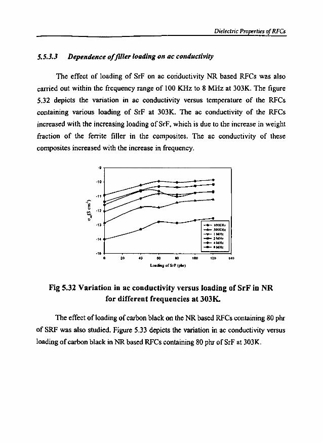
Dielectric Properties of RFCs
5.5.3.3 Dependence offiller loading on ac conductivity
The effect of loading of SrF on ac conductivity NR based RFCs was also
carried out within the frequency range of 100 KHz to 8 MHz at 303K. The figure
5.32 depicts the variation in ac conductivity versus temperature of the RFCs
containing various loading of SrF at 303K. The ac conductivity of the RFCs
increased with the increasing loading of SrF, which is due to the increase in weight
fraction of the ferrite filler in the composites. The ac conductivity of these
composites increased with the increase in frequency.
·e
-10
-11.-.
"'I:" ·12Cl)
;~
·13
-IC
-150
___ 100KHz__ 500KHz
...-IMIlI_JMHI__ cMIlI__ I Mill
20 co eo 10 lOO 120 lCO
Loodina of SrP (phr,
Fig 5.32 Variation in ac conductivity versus loading of SrF in NRfor different frequencies at 303K..
The effect of loading of carbon black on the NR based RFCs containing 80 phr
ofSRF was also studied. Figure 5.33 depicts the variation in ac conductivity versus
loading of carbon black in NR based RFCs containing 80 phr of SrF at 303K.
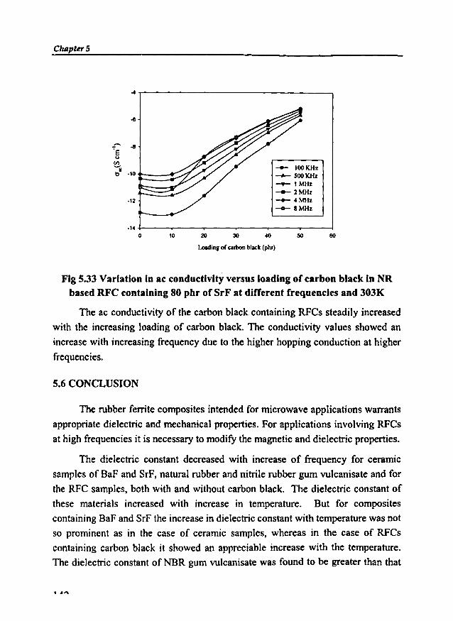
Chtlpter5
... -y-------------------,
..... -8'S..CI:l
11·10"·12
·140 10 20 30
-- 100KHz~ 500KHz-.- I MHz-- 2MHz__ 4MHz
-0- BMHz
50
Loadingof cubon black(phr)
Fig 5.33 Variation in ac conductivity versus loading of carbon black in NRbased RFC containing 80 phr of SrF at different frequencies and 303K
The ac conductivity of the carbon black containing RFCs steadily increased
with the increasing loading of carbon black. The conductivity values showed an
increa,se with increasing frequency due to the higher hopping conduction at higher
frequencies.
5.6 CONCLUSION
The rubber ferrite composites intended for microwave applications warrants
appropriate dielectric and mechanical properties. For applications involving RFCs
at high frequencies it is necessary to modify the magnetic and dielectric properties.
The dielectric constant decreased with increase of frequency for ceramic
samples of BaF and SrF, natural rubber and nitrile rubber gum vulcanisate and for
the RFC samples, both with and without carbon black. The dielectric constant of
these materials increased with increase in temperature. But for composites
containing BaF and SrF the increase in dielectric constant with temperature was not
so prominent as in the case of ceramic samples, whereas in the case of RFCs
containing carbon black it showed an appreciable increase with the temperature.
The dielectric constant of NBR gum vulcanisate was found to be greater than that
......

Dielectric Properties of RFCs
of NR gum vulcanisate, which indicated that that NBR is superior in dielectric
properties compared to NR.
The additionoffenite fillersto both naturaland nitrilerubber increased thedielectric
constant. It was observed that the dielectric constant increases with increase in
volume fraction of the ferrite material. Maximum value of dielectric constant was
observed for a loading of 120phr of ferrite filler. The incorporationof carbon black
into these RFCs increased the dielectric constant values to a greater extent. The dielectric
constant increased substantially even with addition of 10 phr of carbon black into RFCs
containing 80 phr of ferrite fillers. The RFCs containing BaF/SrF in NBR along with
carbon black is superior when compared to RFCs based on NR for dielectricapplications
The ac conductivity increased with frequency for ceramic samples, NR and
NBR gum vulcanisates and rubber ferrite composites containing SrF with and
without carbon black. For the ceramic BaF and SrF the ac conductivity were found
to be almost the same. NBR gum vulcanisate showed high ac conductivity than that
of NR gum vulcanisate. The ac conductivity of the RFCs increased with the
increasing loading of SrF. In the case of carbon black containing RFCs the ac
conductivity steadily increased with the increasing loading of carbon black.
Thus addition of ferrite fillers and appropriate loading of carbon black into
natural and nitrile rubber matrix can modify the dielectric property of the
composites. Microwave absorbers with optimum dielectric and mechanical
properties can be prepared by incorporating BaF and SrF, along with suitable
loading of carbon black in both natural and nitrile rubber matrix.

ChapterS
REFERENCES
1. Safari. A.M, W.Dick, D.H.McQueen, Plastics Rubber and Composites
Processing Appl. 24 (1995) 157.
2. Slama. JR. Vicen, P. Krivosik, A. Grusova, R. Dosoudil, J. Magn. and Magn.
Mater. 196/197 (1999) 359.
3. Arcos. 0, R. Valenzeula, M. Vazquez, M. Vallet-Regi, J. Solid State Chem.
141 (1998) 10.
4. Gigbi. Z. and L.Jilken, J. Magn. Magn. Mater. 37 (1983) 267.
5. Saini D.R, A.V. Sheony and V.M. Nadkami, J. Appl. Polym. Sci. 29 (1983)
4123.
6. Kuar B K, Singh P K, Kishan P, Kumar N, Rao S L N, Prabhat K Singh,
Srivastava G P, J. Appl. Phys. 63 (8) (1988) 3780-3782.
7. El Hiti M A, J. Mag. and Mag. Mat. 164 (1996) 187-196.
8. Josyulu 0 and Sobhanadri J, Phys. Status Solid i(a) 59 (1980) 323.
9. Ahmed M A, El Hiti M A, Mosaad M. M and Attia S M, J. Magn. Magn
Mater. 146 (1995) 84.
10. Murthy V R K and Sobhanadri J, Phys. Status Solid i(a) 36 (1976) 133.
11. Reddy P V and Rao T S, J. Less. Common. Met. 86 (1982) 255.
12. Charles Phelps Smyth, Dielectric Behaviour and Structure, Mc Graw-Hill
Book Company, Inc., 1955.
13. M.R. Anantharaman, S. Sindhu, S. Jagatheesan, K.A. Malini and Philip
Kurian, Journal of Physics D Applied Physics 32 (1999) 1801-1810.
14. M. R. Anantharaman, K.A. Malini, S. Sindhu, E.M. Mohammed,
S.K Date, S.D. Kulkarni, P.A. Joy, and Philip Kurian, Bull. Mater. Sci., 24,6,
(2001) 623-631.
15. Ramasastry C and Syamasundara Rao. Y, J. Phys. E: ScL Instrum.12 (1979)
1023-4.
Dielectric Properties of RFCs
16. Standley K. J, 'Oxide Magnetic Materials'. 2nd edition, (1972), 36, Clarendon
Press, Oxford.
17. Charles Phelps Smyth, Dielectric Behaviour and Structure, Mc Graw-Hill
Book Company, Inc., 1955.
18. M.A. Abdeen, die. Beh. In NZF, J ofMMM,192, (1999) 121-129.
19. V.P. Miroshkin, Ya. P. Panova and V.V. Passynkov, Phys. Stat. So1.(a) 66,
779 (1981).
20. S.A. Mazen M.H. Abdallah, M.A EIghandoor and H.A Hashem, Phys. Stat.
Sol. (a) 144, (1994) 461.
21. C.G. Koops, Phys. Rev. 83 (1951) p 121-124.
22. Tareev B 1979 Physics of Dielectric Materials (Mir Publishers) Moscow.
23. Frank E Karasz 1972 Dielectric Properties of Polymers (Plenum Press) New
York.
24. lP. Suchet, ElectricalConductionIn Solid Materials,PergamonPress, 1975.
25. Andrej Znidarsie and Miha Drofenik J. Ame. Ceram. Soc. 82 (1999) 359.
26. Ahmed M.A and Elhiti M.A, Journal de Physique ill S (1995) 775-781.
27. Abdeen A.M, J. Magn. Magn. Mater. 192 (1999) 121-129.
28. Pal M, Brahma P and Chakravorty D, J. Phys. Soc. Jap, 63, 9 (1994) 3356
3360.
29. Brockman F.G and White R.P, J. Amer. Ceram. Soc. S4 (1971) 183
30. Abdeen A.M, J. Magn. Magn. Mater. 18S (1998) 199 - 206.
31. Elhiti M.A, J. Magn. Magn. Mater. 164 (1996) 187 -196.
32. C. Prakash, J.S. Bijal, P. Kishan, J. Less- common Met. 106 (1985) 243
33. AB. Naik, J.J. Powar, Ind. J. Pure Appl. Phys. 239 (1985) 436.
34. R. Satyanarayana, S.R. Murthy, Crystal Res. Technol. 20 (1985) 701.
35. S. Jankowski, J. Amer. Ceram. Soc., 71 (1988) C-176.
36. P.V. Reddy, R. Satyanarayana, T.S. Rao, Phys. S13t. Sol. (a) 78 (1983) 109
ChapterS
37. F. Haberey, H.J.P.Wijn, Phys. Stat. Sol. (a) 26 (1968) 231.
38. D.A. Seanor (edt.) Electrical properties of Polymers, Academic press New
York, 1982.
39. Ya. M. Paushkin, T.P. Vishnyakova, A.F. Lunin, S.A. Nizova, Organic Polymeric
Semiconductors, Keter Publishing House Jerusalem Ltd, 1974.
40. James M. Margolis, (Edt), Conductive Polymers and Plastic, Chapman and
Hall, New York, 1989.
146
Chapter 6
MAGNETIC PROPERTIES OF RUBBERFERRITE COMPOSITES
6.1 INTRODUCTION
It is well known that polycrystalline ferrite ceramic powders can be
incorporated in various elastomer matrixes to produce rubber ferrite composites 1.7,
The incorporation of these ferrite powders can be carried out both in natural and
synthetic rubber matrix to produce flexible magnets. They have the special
advantage of easy processability into complex shapes, which is not possible with
conventional ceramic materials. The impregnation of magnetic fillers in the
polymer matrixes can, not only bring economy but also imparts magnetic
properties to the matrix. They also modify the dielectric and mechanical properties
of the composites 8.9. These flexible elastomer magnets find extensive applications
in microwave absorbers and other devices, where flexibility and mouldability are
important criteria. For applications involving microwave absorption it is essential
that the materials warrant an appropriate permittivity and a desirable magnetic
property 8.13. This can be achieved in single step by synthesising rubber ferrite
composites.
Rubber ferrite composites can be synthesised by the incorporation of ferrite
powders in natural or synthetic rubber matrixes. Both the soft and hard ferrites can be
embedded in the rubber matrix. It has been reported that flexible magnets with
appropriate magnetic properties can be made by judicious choice of soft ferrites like
Chapter 6
nickel zinc ferrite and manganese zinc ferrite in both natural and butyl rubber
matrix":", The incorporation of hard ferrites in the elastomer matrix can produce
flexible permanent magnets, which find widespread applications. The preparation of
RFCs and evaluation of various properties such as magnetic, dielectric and
mechanical assumes significance not only in tailor making composites but also in
understanding the fundamental aspects that govern these properties. The results of
investigation on the magnetic properties of ceramic barium ferrite and strontium
ferrite and RFCs containing these ferrites are discussed in this chapter.
Hard ferrites namely barium ferrite and strontium ferrite have been prepared
using ceramic processing techniques. The details are described in chapter 3. These
hexagonal ferrites were then incorporated in natural rubber and nitrile rubber matrix
at different loadings according to a specific recipe as cited in chapter 3. The RFCs
containing various loading of carbon black were also prepared. Magnetic properties
were evaluated for BaF, SrF and rubber ferrite composites with and without carbon
black. From the magnetic data obtained for the ceramic fillers and RFCs, the
variation in magnetic properties with loading of ferrite filler and carbon black were
studied. A general relationship connecting the magnetic property of the ceramic filler
and the composites were correlated using equation 6.1. The validity of the equation
was then checked using observed data and the calculated values of magnetisation.
6.2 MAGNETIC MEASUREMENTS
Magnetic measurements of the ceramic barium ferrite, strontium ferrite and
rubber ferrite composites with and without carbon black were carried out using
Vibrating Sample Magnetometer (VSM) model:4500 (EG&G PARC) at room
temperature, as explained in chapter2. The hysteresis loop parameters namely
saturation magnetisation (Ms), magnetic remanence or retentivity (Mr) and
coercivity (Hc) were evaluated.
6.2.1 Ceramic samples.
Magnetic properties of the ceramic barium ferrite and strontium ferrite were
evaluated at room temperature (303K). Figures 6.1 and 6.2 shows the hysteresis
loop for the ceramic barium ferrite and strontium ferrite respectively.

Magnetic Properties of RFCs
-15000 -10000
60
10000 15000
H in Oersted
Fig 6.1 Hysteresis loop of ceramic BaF
The hysteresis loop parameters of the ceramic ferrites have confirmed the
magnetic character. The saturation magnetisation (Ms) and coercivity (He) of BaF
is slightly higher than that ofthe SrF, whereas the magnetic remanence (Mr) ofBaFis slightly lower than that of SrF. The measured values of saturation magnetisation
of these ceramic ferrites matched well with that of the reported values.
·15000 -10000
60
10000 15000
H in Oersted
Fig 6.2 Hysteresis loop of ceramic SrF
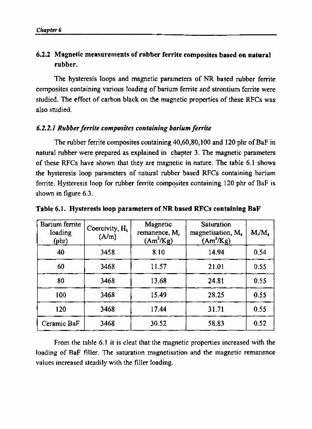
Chapter 6
6.2.2 Magnetic measurements of rubber ferrite composites based on naturalrubber.
The hysteresis loops and magnetic parameters of NR based rubber ferrite
composites containing various loading of barium ferrite and strontium ferrite were
studied. The effect of carbon black on the magnetic properties of these RFCs was
also studied.
6.2.1.1 Rubberferrite composites containing barium ferrite
The rubber ferrite composites containing 40,60,80, t00 and t20 phr ofBaF in
natural rubber were prepared as explained in chapter 3. The magnetic parameters
of these RFCs have shown that they are magnetic in nature. The table 6.1 shows
the hysteresis loop parameters of natural rubber based RFCs containing barium
ferrite. Hysteresis loop for rubber ferrite composites containing 120 phr of BaF is
shown in figure 6.3.
Table 6.1. Hysteresis loop parameters of NR based RFCs containing BaF
Barium ferriteCoercivity, He
Magnetic Saturationloading remanence, M, magnetisation, M, Mr'Ms
(phr) (Nm)(Am2/Kg) (Am2/Kg)
40 3458 8.10 14.94 0.54
60 3468 11.57 21.01 0.55
80 3468 13.68 24.81 0.55
100 3468 15.49 28.25 0.55
120 3468 17.44 31.71 0.55
Ceramic BaF 3468 30.52 58.83 0.52
From the table 6.1 it is cleat that the magnetic properties increased with the
loading of BaF filler. The saturation magnetisation and the magnetic remanence
values increased steadily with the filler loading.

MagneticProperties of RFCs
H in Oersted
-15000 ·10000
·30
10000 15000
-40
Fig 6.3 Hysteresis loop of natural rubber based RFCcontaining 120 phr of BaF
The variation in magnetic remanence with loading of BaF in NR based RFCs
is shown in figure 6.4. It increased with the loading of ferrite filler.
18.,---------------------,
~ 16
--
140120100806020
6+-----..,,.-----"'T-----r---,---..,......----..,,.----lo
Loadingof BaF(phr)
Fig 6.4 Variation in magnetic remanence versusloading of BaF in NR

Chapter 6
The variation in coercivity with loading of BaF in natural rubber is shown in
figure 6.5. It showed almost same value as that of the ceramic component. It is
reported that the coercivity of ceramic samples mainly depend on parameters like
sintering conditions and particle size 2,16. The slight variations in coercivity
between the ceramic and composites can occur due to the particle size reduction
that takes place during compounding and mixing. However this variation is
negligible. From this observation it can be concluded that loading of BaF has no
effect on coercivity of RFCs.
~l\OO
3575
lS'O
E$ H2'
"::t:i- lSOO
:E
~l4'S
~4S0
l42'
Hoo0 20
•
40
•
60
•
80
•
100
•
120 140
Lollding of OaF (phr)
Fig 6.5 Variation in coercivity with loading ofBaF in natural rubber
6.2.2.2 Effect ofcarbon black on the magnetic properties ofRFC containing
barium ferrite
Carbon black was incorporated into NR based RFC containing 80 phr of BaF
and its magnetic properties were evaluated. The table 6.2 shows the hysteresis loop
parameters of these rubber ferrite composites. It indicated that the saturation
magnetisation and the magnetic remanence decreased with increase in the loading of
carbon black. The decrease in the magnetic properties with the incorporation of
carbon black is due to the reduction in the weight fraction of the magnetic component
in the RFCs. However the coercivity values did not show much variation with the
addition ofcarbon black.
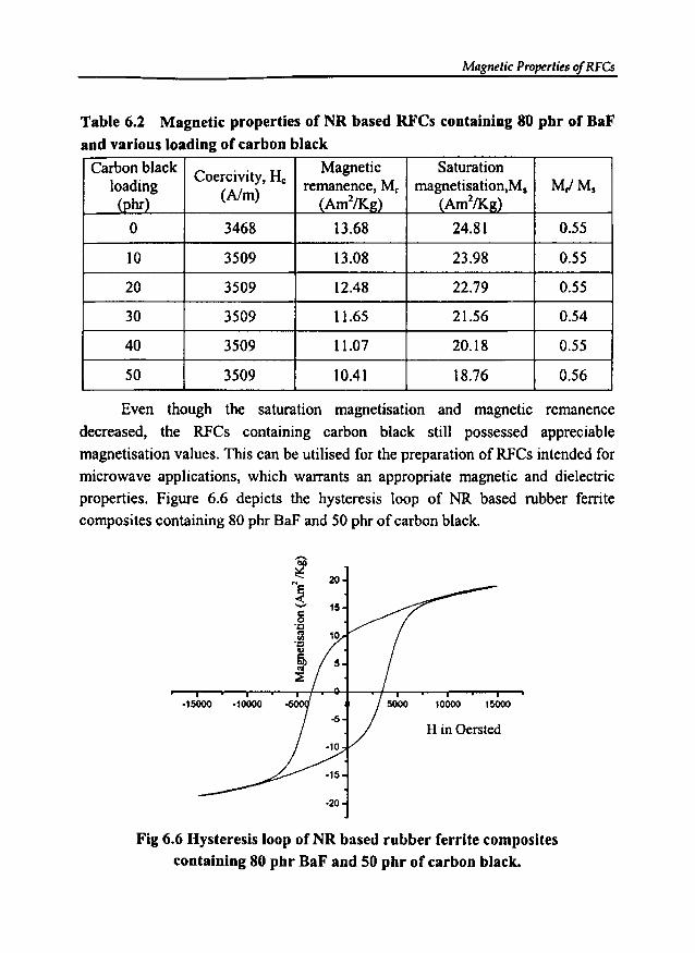
Magnetic Properties of RFCs
Table 6.2 Magnetic properties of NR based RFCs containing 80 phr of BaFand various loading of carbon black
Carbon blackCoercivity, He Magnetic Saturation
loading remanence, M, magnetisation.M, M/Ms(phr) (Nm)
(Am21K.~) (Am21K.~)
0 3468 13.68 24.81 0.55
10 3509 13.08 23.98 0.55
20 3509 12.48 22.79 0.55
30 3509 11.65 21.56 0.54
40 3509 11.07 20.18 0.55
50 3509 10.41 18.76 0.56
Even though the saturation magnetisation and magnetic remanence
decreased, the RFCs containing carbon black still possessed appreciable
magnetisation values. This can be utilised for the preparation of RFCs intended for
microwave applications, which warrants an appropriate magnetic and dielectric
properties. Figure 6.6 depicts the hysteresis loop of NR based rubber ferrite
composites containing 80 phr BaF and 50 phr of carbon black.
·15000 ·10000
20
·20
10000 15000
H in Oersted
Fig 6.6 Hysteresis loop of NR based rubber ferrite compositescontaining 80 phr BaF and 50 phr of carbon black.
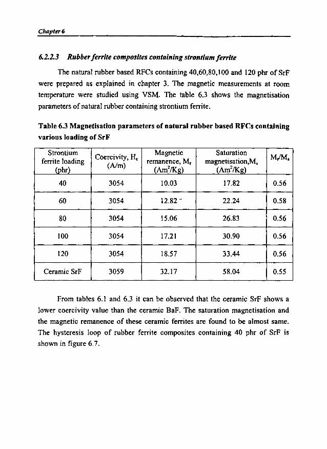
Chapter 6
6.2.2.3 Rubber ferrite composites containing strontium ferrite
The natural rubber based RFCs containing 40,60,80,100 and 120 phr of SrF
were prepared as explained in chapter 3. The magnetic measurements at room
temperature were studied using VSM. The table 6.3 shows the magnetisation
parameters of natural rubber containing strontium ferrite.
Table 6.3 Magnetisation parameters of natural rubber based RFCs containing
various loading of SrF
StrontiumCoercivity, He Magnetic Saturation
MIMsferrite loading rernanence, M, magnetisation.M,(phr)
(Nm)(Am21K~) (Am21K~)
40 3054 10.03 17.82 0.56
60 3054 12.82 - 22.24 0.58
80 3054 15.06 26.83 0.56
100 3054 17.21 30.90 0.56
120 3054 18.57 33.44 0.56
Ceramic SrF 3059 32.17 58.04 0.55
From tables 6.1 and 6.3 it can be observed that the ceramic SrF shows a
lower coercivity value than the ceramic BaF. The saturation magnetisation and
the magnetic remanence of these ceramic ferrites are found to be almost same.
The hysteresis loop of rubber ferrite composites containing 40 phr of SrF is
shown in figure 6.7.

Magnetic Properties of RFCs
......~ 20N~
15'-'
8'&:~'ij
~::E
-15000 -rooee ioooe 15000
H in Oersted
Fig 6.7 Hysteresis loop of NR based rubber ferrite
composites containing 40 phr of SrF
The table 6.3 shows that the magnetic properties of these composites increase
with the loading of SrF filler. The saturation magnetisation and the magnetic
remanence values increased steadily with the loading of SrF. The variation of M, and
M, for different loading ofSrF is shown in figures 6.8 and 6.9 respectively.
36
00N~ 32
~~.: 28
:t 24~..,8
j 20
18
0 20 40 60 80 100 120 140
Loading of SrF (phr)
Fig 6.8 Variation in saturation magnetisation withloading of SrF in NR based RFCs

Chapter 6
20.,--------------------,
~ 18:.:
! 16
::{
~ 14
I.~ 12
i~ 10
1401201008040208f---,--...,.....--..------.-----,----,,.------l
o
Loading of Srf (phr)
Fig 6.9 Variation in magnetic remanence with
loading of SrF in NR based RFCs
The coercivity values of the RFCs containing SrF also showed a similar
behaviour as that of the ceramic component. The variation in coercivity of NR
based RFCs with loading of SrF is shown in fig. 6.10.
3058.0
30555
! 30550
u:c
:t 3054.5
~ 3054.0U
3053.5
3053.00 20
•
40
•
60
•
80
•
100
•
120 140
loading of SrF (phr)
Fig 6.10 Variation in coercivity with loading ofSrF
in natural rubber based RFCs
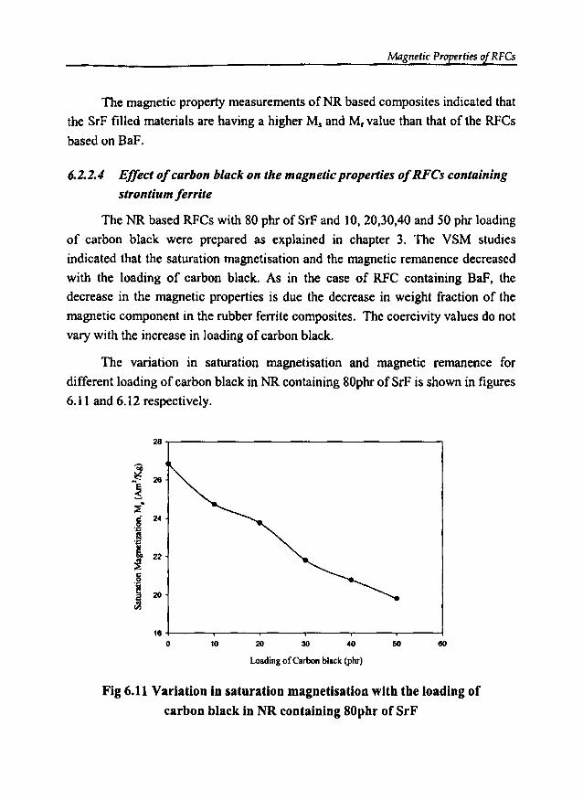
Magnetic Properties of RFCs
The magnetic property measurements ofNR based composites indicated that
the SrF filled materials are having a higher M, and M, value than that of the RFCs
based on BaF.
6.2.2.4 Effect ofcarbon black on the magnetic properties ofRFCs containing
strontium ferrite
The NR based RFCs with 80 phr of SrF and 10, 20,30,40 and 50 phr loading
of carbon black were prepared as explained in chapter 3. The VSM studies
indicated that the saturation magnetisation and the magnetic remanence decreased
with the loading of carbon black. As in the case of RFC containing BaF, the
decrease in the magnetic properties is due the decrease in weight fraction of the
magnetic component in the rubber ferrite composites. The coercivity values do not
vary with the increase in loading of carbon black.
The variation in saturation magnetisation and magnetic remanence for
different loading of carbon black in NR containing 80phr of SrF is shown in figures
6.11 and 6.12 respectively.
28
'Oil..~: 26
!~.
C 240
'D
.~
~ 22~c
'I 20
'"18
0 10 20 30 40 50 60
Loading of Carbon black(phr)
Fig 6.11 Variation in saturation magnetisation with the loading of
carbon black in NR containing 80pbr of SrF

CluJpter6
18T"""'-------------------,
80504030201010 -f-----.----.---....---....---""T"""----I
o
Loading ofcarbon black (phr)
Fig 6.12 Variation in magnetic remaqence with the loading of
carbon black in NR containing 80phr of SrF
Figure 6.13 shows the hysteresis loop ofNR based rubber ferrite composites
containing 80 phr ofSrF and 50 phr of carbon black.
-15000 ·10000
20
10000 15000
H in Oersted
Fig 6.13 Hysteresis loop of NR based RFCs containing80 phr SrF and SO phr of carbon black
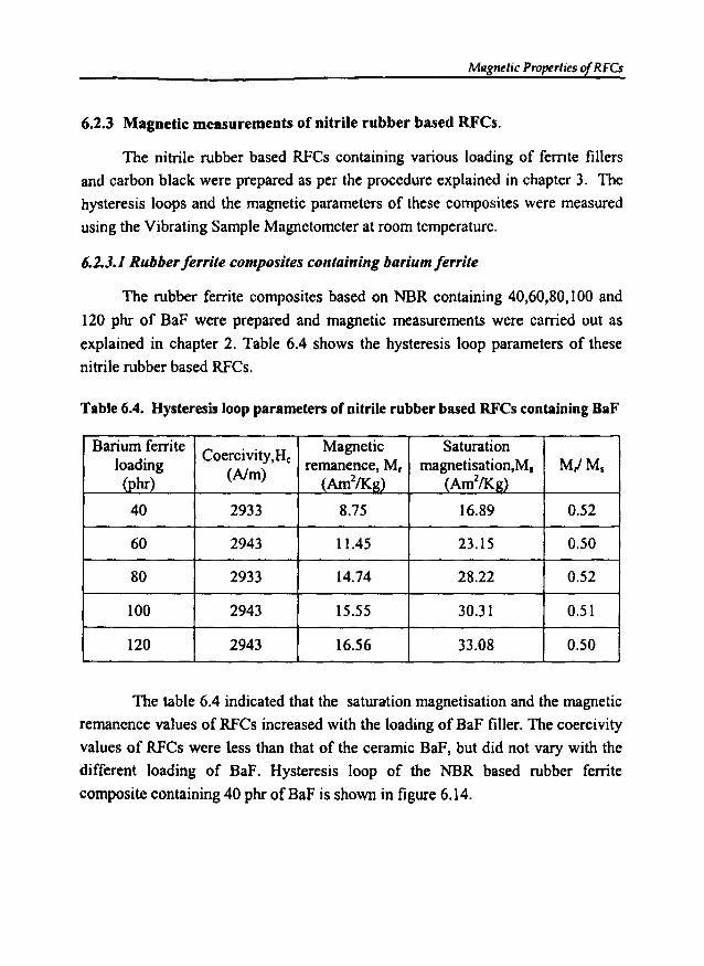
Magnetic Properties of RfCs
6.2.3 Magnetic measurements of nitrile rubber based RFCs.
The nitrile rubber based RFCs containing various loading of ferrite fillers
and carbon black were prepared as per the procedure explained in chapter 3. The
hysteresis loops and the magnetic parameters of these composites were measured
using the Vibrating Sample Magnetometer at room temperature.
6.2.3.1 Rubberferrite composites containing barium ferrite
The rubber ferrite composites based on NBR containing 40,60,80, I00 and
120 phr of BaF were prepared and magnetic measurements were carried out as
explained in chapter 2. Table 6.4 shows the hysteresis loop parameters of these
nitrile rubber based RFCs.
Table 6.4. Hysteresis loop parameters of nitrile rubber based RFCs containing BaF
Barium ferrite Coercivity.H, Magnetic Saturationloading remanence, M, magnetisation,M, M,IMs
(phr)(Nm)
(Am2/K2) (Am2/Kg)
40 2933 8.75 16.89 0.52
60 2943 llA5 23.15 0.50
80 2933 14.74 28.22 0.52
100 2943 15.55 30.31 0.51
120 2943 16.56 33.08 0.50
The table 6.4 indicated that the saturation magnetisation and the magnetic
remanence values of RFCs increased with the loading of BaF filler. The coercivity
values of RFCs were less than that of the ceramic BaF, but did not vary with the
different loading of BaF. Hysteresis loop of the NBR based rubber ferrite
composite containing 40 phr ofBaF is shown in figure 6.14.
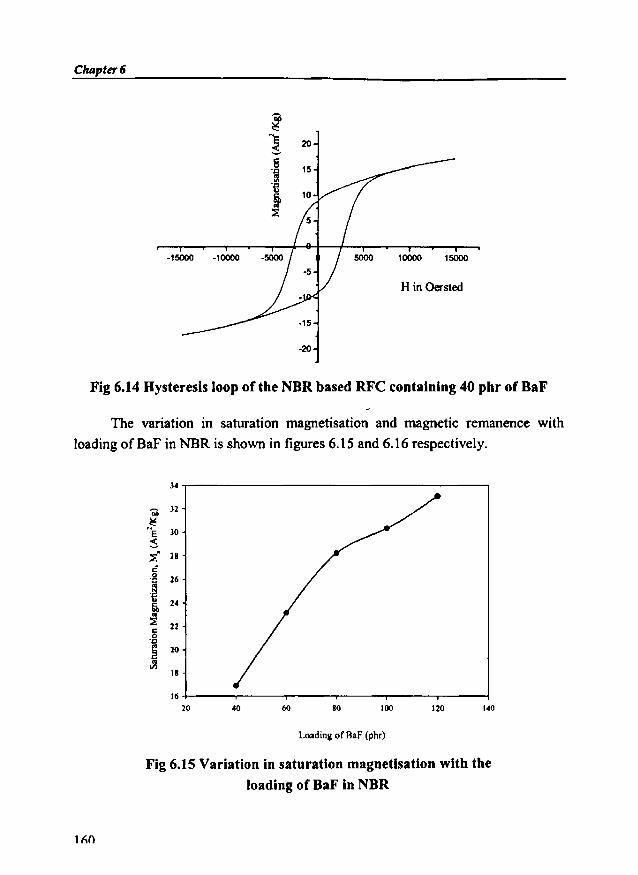
ChApter 6
-15000 -10000
20
15
10000 15000
H in Oersted
·15
-20
Fig 6.14 Hysteresis loop of the NBR based RFC containing 40 phr of BaF
The variation in saturation magnetisation and magnetic remanence with
loading ofBaF in NBR is shown in figures 6.15 and 6.16 respectively.
34 -r----------------------,
18
140
16 .j----r---~--___r--__..,.---.___---1
20
Loading of BaF (phr)
Fig 6.15 Variation in saturation magnetisation with the
loading of BaF in NBR
11\0
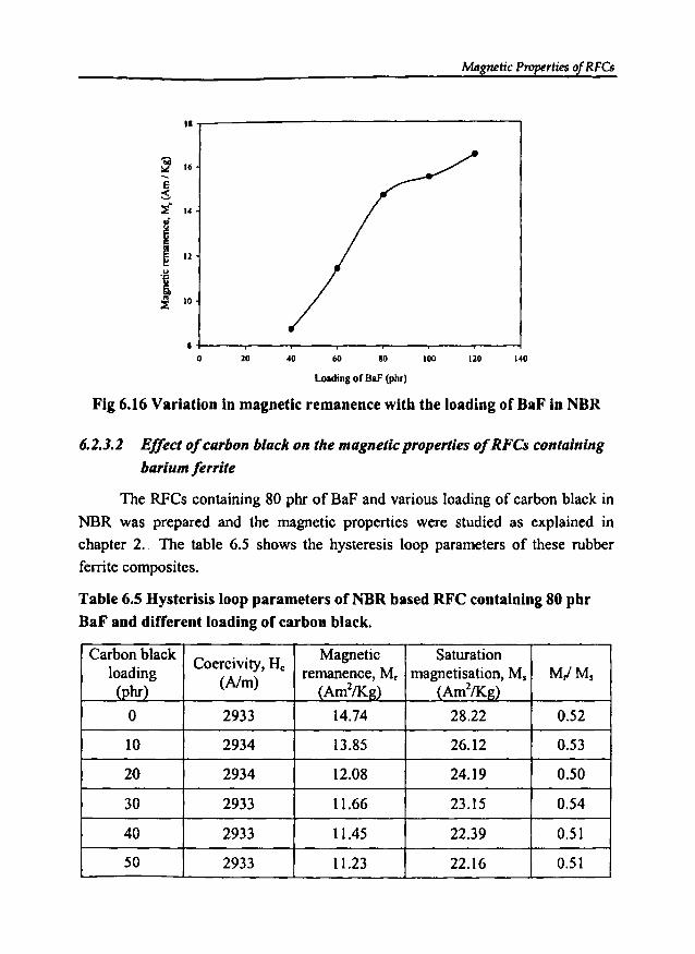
Magnetic Properties ofRFCs
18.,..------------------,
~ 16-Es'::f 14
i~ 12
.~
~:i 10
14012010080604020
8 +---..----r----r---~-_r_-____,----l
o
loading of OaF(phr)
Fig 6.16 Variation in magnetic remanence with the loading of BaF in NBR
6.2.3.2 Effect ofcarbon black on the magneticproperties ofRFCs containing
barium ferrite
The RFCs containing 80 phr of BaF and various loading of carbon black in
NBR was prepared and the magnetic properties were studied as explained in
chapter 2. The table 6.5 shows the hysteresis loop parameters of these rubber
ferrite composites.
Table 6.5 Hysterisis loop parameters of NBR based RFC containing 80 phr
BaF and different loading of carbon black.
Carbon blackCoercivity, He Magnetic Saturation
loading remanence, Mr magnetisation, Ms M,IMs(phr) (Nm) (Am2fKg) (Am2/Kg)
0 2933 14.74 28.22 0.52
10 2934 13.85 26.12 0.53
20 2934 12.08 24.19 0.50
30 2933 11.66 23.15 0.54
40 2933 11.45 22.39 0.51
50 2933 11.23 22.16 0.51
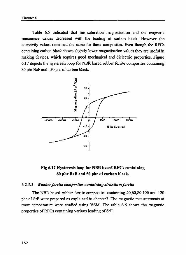
Chapter 6
Table 6.5 indicated that the saturation magnetisation and the magnetic
remanence values decreased with the loading of carbon black. However the
coercivity values remained the same for these composites. Even though the RFCs
containing carbon black shows slightly lower magnetisation values they are useful in
making devices, which requires good mechanical and dielectric properties. Figure
6.17 depicts the hysteresis loop for NBR based rubber ferrite composites containing
80 phr BaF and 50 phr ofcarbon black.
-IS000 ·10000
:10
20
10000 1SOOO
H inOented
·:10
Fig 6.17 Hysteresis loop for NBR based RFCs containing
80 phr BaF and 50 phr of carbon black.
6.2.3.3 Rubber ferrite composites containing strontium ferrite
The NBR based rubber ferrite composites containing 40,60,80,100 and 120
phr of SrF were prepared as explained in chapter3. The magnetic measurements at
room temperature were studied using VSM. The table 6.6 shows the magnetic
properties ofRFCs containing various loading ofSrF.
1f\?
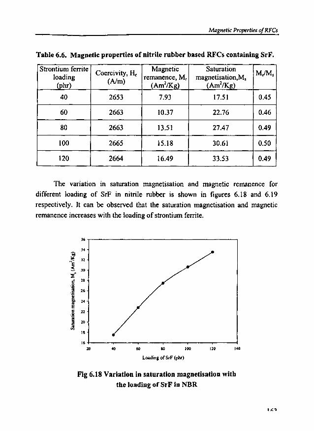
Magnetic Properties of RFCs
Table 6.6. Magnetic properties of nitrile rubber based RFCs containing SrF.
Strontium ferriteCoercivity, He Magnetic Saturation
MlMsloading remanence, M, magnetisation,M,(phr)
(AIm) (Am1/Kg) (Am1/Kg)
40 2653 7.93 17.51 0.45
60 2663 10.37 22.76 0.46
80 2663 13.51 27.47 0.49
100 2665 15.18 30.61 0.50
120 2664 16.49 33.53 0.49
The variation in saturation magnetisation and magnetic remanence for
different loading of SrF in nitrile rubber is shown in figures 6.18 and 6.19
respectively. It can be observed that the saturation magnetisation and magnetic
remanence increases with the loading of strontium ferrite.
J6-r--------------------,bil~ 32~e
~ 30
~:<! 28.g11 26'C
~ 24E.§ 22
S 20
'" III
140120100so60
16+---..----...----,.------.--"'"""T----l20
Loading of SrF (piu)
Fig 6.18 Variation in saturation magnetisation with
the loading of SrF in NBR
11::'1

CIulpter6
18T""""--------------------,
14012010080604020
6-f---.-----.---..........--,..-----,---""T"""'"-----to
Loading ofSrF (phr)
Fig 6.19 Variation in magnetic remanence with theloading of SrF in NBR based RFCs
6.1.3.4 Effect ofcarbon black on the magnetic properties ofREes containing
strontium ferrite
The rubber ferrite composites containing 10,20,30,40 and 50 phr loading of
carbon black along with 80 phr of strontium ferrite in nitrile rubber were prepared
as explained in chapter 3. The VSM studies indicated that the saturation
magnetisation and the magnetic remenance values decreased with the loading of
carbon black, which can be explained by the decrease in the weight fraction of the
ferrite material in the composites. The coercivity values remained constant for the
increase in loading of carbon black. The table 6.7 shows the hysteresis loop
parameters of nitrile rubber containing strontium ferrite and various loading of
carbon black. From tables 6.1 to 6.7, it can be observed that the MMs values of
the rubber ferrite composites both with and without carbon black remains almost
the same as that of the ceramic ferrites.
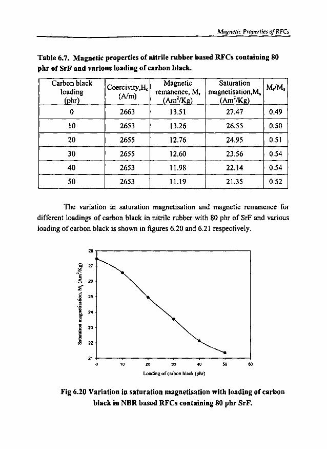
Magnetic Properties of RFCs
Table 6.7. Magnetic properties of nitrile rubber based RFCs containing 80pbr of SrF and various loading of carbon black.
Carbon blackCoercivity.H,
Magnetic SaturationMMsloading remanence, M, magnetisation.M,
(phr) (Nm)(Am2/K g) (Am2/Kg)
0 2663 13.51 27.47 0.49
10 2653 13.26 26.55 0.50
20 2655 12.76 24.95 0.51
30 2655 12.60 23.56 0.54
40 2653 11.98 22.14 0.54
50 2653 11.19 21.35 0.52
The variation in saturation magnetisation and magnetic remanence for
different loadings of carbon black in nitrile rubber with 80 phr of SrF and various
loading of carbon black is shown in figures 6.20 and 6.21 respectively.
28
... zr
1 28
~-
C 250'f:IX'ij
24tc
23.S!
I 22
210 10 20 30 40 50 60
Loadingor carbon black (phr)
Fig 6.20 Variation in saturation magnetisation witb loading of carbon
black in NBR based RFCs containing 80 pbr SrF.
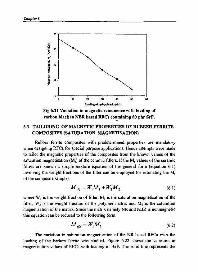
Chapt" 6
14 -r------------------,
60504030201010 ~--r__-_____.--__._--__,__--__.__---l
oLoadingof carbonblack(phr)
Fig 6.21 Variation in magnetic remanence with loading of
carbon black in NBR based RFCs containing 80 phr SrF.
6.3 TAILORING OF MAGNETIC PROPERTIES OF RUBBER FERRITECOMPOSITES (SATURATION MAGNETISATION)
Rubber ferrite composites with predetermined properties are mandatorywhen designing RFCs for special purpose applications. Hence attempts were madeto tailor the magnetic properties of the composites from the known values of thesaturation magnetisation (Ms) of the ceramic fillers. If the M, values of the ceramicfillers are known a simple mixture equation of the general form (equation 6.1)involving the weight fractions of the filler can be employed for estimating the M,of the composite samples.
(6.1)
where W, is the weight fraction of filler, M, is the saturation magnetisation of thefiller, W2 is the weight fraction of the polymer matrix and M2 is the saturationmagnetisation of the matrix. Since the matrix namely NR and NBR is nonmagneticthis equation can be reduced to the following form
(6.2)
The variation in saturation magnetisation of the NR based RFCs with theloading of the barium ferrite was studied. Figure 6.22 shows the variation inmagnetisation values of RFCs with loading of BaF. The solid line represents the
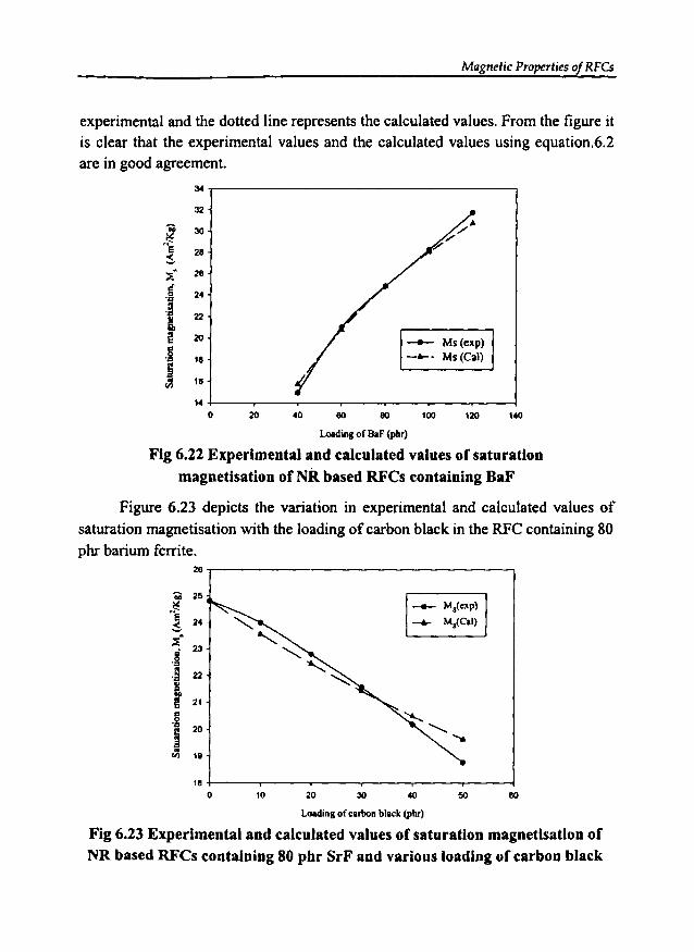
Magnetic Properties of RFCs
experimental and the dotted line represents the calculated values. From the figure itis clear that the experimental values and the calculated values using equation.6.2are in good agreement.
140120100
- Ms(exp)- .... Ms(CaJ)
eoeo4020
:w
32
N~30
28~
":i." 28
of0 24'Q
.;22t 20
.g 18
i~ 18
140
Loadingof BaF(piu)
Fig 6.22 Experimental and calculated values of saturationmagnetisation of NR based RFCs containing BaF
Figure 6.23 depicts the variation in experimental and calculated values ofsaturation magnetisation with the loading of carbon black in the RFC containing 80phr barium ferrite.
28 ~------------------,
eo504030201018 +---~--.-------,.-------,.----,.---l
oLoading of carbonblack(pm)
Fig 6.23 Experimental and calculated values of saturation magnetisation ofNR based RFCs containing 80 phr SrF and various loading of carbon black
Chapter 6
As expected the values decreased due to the decrease in the weight fraction
of the magnetic component. The saturation magnetisation of RFCs containing
different loading of carbon black was calculated by employing equation 6.2
considering carbon black as non magnetic filler. These were then compared with
the experimental values. From the figure it was found that that the experimental
values agreed well with the calculated values
6.4 CONCLUSION
Rubber ferrite composites containing barium ferrite and strontium ferrite in
natural rubber and nitrile rubber matrix were prepared. Magnetic parameters of the
ceramic ferrites as well as that of the RFCs were studied. Study of the magnetic
properties indicated the formation of elastomer magnets with suitable saturation
magnetisation and magnetic remanence. The saturation magnetisation and the
magnetic remanence increased with increase in the loading of barium ferrite and
strontium ferrite. The coercivity of the RFCs remained almost same as that of the
ceramic component. The effect of carbon black on the magnetic properties of these
RFCs was also studied. The magnetic measurements indicated that the saturation
magnetisation and the magnetic remanence decreased with the loading of carbon
black. However the coercivity was not affected with increasing loading of carbon
black. From the magnetic property studies of both natural and nitrile rubber based
RFCs containing barium ferrite and strontium ferrite, it can be observed that the
matrix material does not have significant effect on saturation magnetisation and
magnetic remanence.
By synthesising RFCs, we have the exceptional advantage of modifying
saturation magnetisation and magnetic remanence according to the requirement.
Hence the desired magnetic property can be imparted by appropriate loading of
ferrite fillers. The calculated values tally well with the experimental values of the
saturation magnetisation, which indicate that it is possible to modify materials with
a definite magnetisation value by appropriate loading of barium ferrite and
strontium ferrite filler in both the NR and NBR matrix. Hence the relationship
connecting the magnetisation (Ms) of RFC with the magnetisation of the respective
fillers can be employed to tailor magnetic properties
Magnetic Properties of RFCs
REFERENCES
1. Hadfield D, 'Permanent Magnets and Magnetism', John Wiley and sons, Inc.
London 1962.
2. Cullity RD, 'Introduction to Magnetic Materials', 1972, Philippines, Addison
Wesley Publishing Company, Inc.
3. Safari Ardi M, Dick W and McQueen D.H, Plastic Rubber and Composites
Processing Applications, 24 (1995) 157-164.
4. Anantharaman M. R, S. Jagatheesan, S. Sindhu, K. A. Malini, C. N. Chinnasamy,
A. Narayansamy, P. Kurian and K. Vasudevan, Plastic Rubber and Composites
Processing Applications, 27, 2 (1998) 77-81.
5. Anantharaman M.R, S. Sindhu, S. Jagatheesan, K.A. Malini and Philip Kurian,
Journal of Physics D Applied Physics 32 (1999) 1801-1810.
6. Praveen Singh & T.e. Goel: Indian J. Pure and Appl Phys.,38 (2000) 213-219.
7. Anantharaman M. R, P. Kurian, B. Banerjee, E. M. Mohammed, and
M. George, Kautschuk Gununi Kunststoffe, (Germany), 49, 6/96, 424- 426.
8. Jozef Slama, Anna Gruskova, L'udovit Keszegh, Mojmir Kollar: IEEE Trans.
Mag., 3D, 2 (1994) 1101-1103.
9. Osawa. Z, K. Kawaguehi, M. Iwata, H.Harada, J.Mater. Sei.23 (1988) 2637-44.
10. Mitsuo Sugimoto, Journal ofAmerican Ceramic Society. 82,2 (1999) 269- 279.
11. H. Takei, H. Tokumasu, H. Rikukawa and I. Sasaki, IEEE Trans. Mag. Vol
MAJ 23 (1987) 3080-3082.
12. A.M. Sankpal, S.S. Suryavanshi, S.V. Kakatbar, G.G. Tengshe, R.S. Patil,
N.D. Chaudhari, S.R. Sawant, 1. Mag. Magn. Mater. 186 (1998) 349-356.
13. T. Nakamura, T. Tsutaoka, K. Hatekeyama, J. Mag. Mag. Mater. 138 (1994)
319- 328.
14. K.A. Malini, E.M. Mohammed, S. Sindhu, P.A. Joy, S.K. Date, S.D. Kulkami,
P. Kurian and M.R. Anantharaman, J. Mater. Sci.36 (2001),5551-5557.
15. Anantharaman. M.R, K.A. Malini, S.Sindhu, E.M. Mohammed, S.K. Date,
P.A. Joy and Philip Kurian, Bull. Mater. Sci., 24, 6, (2001) 623-631.
16. Smit. J and H.PJ. Wijn, 'Ferrites', 1959, Phi lips Technical library.
Chapter 7
SUMMARY AND CONCLUSION
This concluding chapter provides a glimpse of the conclusions drawn from
the work carried out on the subject of rubber ferrite composites and the scope for
the future work on rubber ferrite composites (RFC).
Composites play a major role in the science and technology of the present
day. The magnetic polymer composites especially rubber ferrite composites is one
of the many composite materials in which the scientist and engineers are interested
and find scope for possible exploitation of commercial applications. Here attempts
have been made to prepare magnetic rubber composites. Ferrites are ferrimagnetic
materials and come under a group of technologically important magnetic materials,
which has received the greatest attention and cannot be easily replaced by any
other magnetic materials as they are stable, economical and possess a wide range
of applications. Brittleness of the ceramic magnetic materials is one of the
difficulties faced in the application point of view. Here the magnetic composites
can play a very crucial role. Rubber ferrite composites are magnetic polymer
composites made of ferrite fillers and natural or synthetic rubber matrix. This
rubber ferrite composite has the advantage of easy fabrication into complex shapes.
Flexibility with the required mechanical strength is another hallmark of these
composites. These composites can be used as potential microwave absorbers in a
wide range of frequencies due to its dielectric properties, low cost, lightweight and
Chapter 7
design flexibility. Therefore, preparation and characterisation ofRFCs is important
and assumes significance
7.1 SUMMARY
The main focus of this study was to synthesise, characterise and investigate
the magnetic, dielectric and mechanical properties of rubber ferrite composites
based on natural rubber (NR) and nitrile rubber (NBR). Hard ferrites namely
barium ferrite (BaF) and strontium ferrite (SrF) in the monophasic form were
prepared and characterised. These precharacterised magnetic fillers are then
incorporated into two different matrixes, natural and nitrile rubber separately, to
produce rubber ferrite composites. The hard ferrites are selected, to produce
flexible permanent magnets. The natural rubber is chosen as one of the polymer
matrixes because of its easy availability and low cost, whereas the nitrile rubber is
selected as the other matrix material considering its superior properties and special
purpose application.
The thesis consists of seven chapters, where the Chapter 1 gives a general
introduction to the polymers, rubber ferrite composites, magnetic materials, their
classification, applications and the main objectives of the thesis. Chapter 2 presents
a general discussion of the materials used and the experimental techniques employed
for the preparation and characterisation of the samples. Chapter 3 to 6 gives the
details of the findings of the work carried out on RFCs. The present chapter gives the
summary and conclusions of the findings described in each chapter.
Chapter 3 described the preparation and characterisation of the ferrites and
its incorporation into rubber matrixes to produce the rubber ferrite composites.
Hexagonal hard ferrites namely barium ferrite and strontium ferrites were prepared
by the ceramic techniques. Structural evaluations of the prepared BaF and SrF
samples were carried out using X-ray diffraction (XRD) method. These samples
were checked for their monophasic characteristics before they were incorporated in
to the rubber matrixes. RFCs were prepared by incorporating these
precharacterised powder samples into NR and NBR matrixes for various loadings
according to a specific recipe. The addition of carbon black is known to reinforce
the rubber matrix; moreover studies have indicated that the addition of fillers like

Summary and Conclusion
carbon black on rubber ferrite composites enhances the microwave absorbing
properties of the composites. Hence the carbon black filled RFCs were prepared by
incorporating varying amount of carbon black into RFC containing an optimum
quantity of ferrite.
The Cure Characteristics and mechanical properties of the of rubber ferrite
composites are discussed in Chapter 4. Evaluation of the cure characteristics
indicated that RFCs containing barium ferrite and strontium ferrite with and
without carbon black reduces both the scorch time and cure time, whereas the
minimum and maximum torque values increases with the addition of these
materials. The studies also revealed that the processability of the composites is not
much affected even up to a loading of 120 phr of ferrite fillers.
Evaluation of the mechanical properties has shown that the addition of
magnetic fillers improves the modulus and hardness but slightly reduces the
elongation at break. The addition of the ferrites into the natural rubber matrix
reduced the tensile strength slightly, because of the inhibition in stress induced
crystallization of the NR matrix. But in the case of NBR, the addition of ferrites
increases the tensile strength, since it reinforces the NBR matrix. The tensile
strength reduced at higher loading of the ferrite filler due to the dilution effect.
The incorporation of carbon black to both natural and nitrile rubber
increased the tensile strength significantly, since it is a good reinforcing filler. The
studies also indicated that the percolation threshold was not reached for a
maximum loading of 120 phr of the filler. Hence after attaining the required
magnetic property, if the percolation limit is not reached, the mechanical properties
of RFCs can be enhanced by the addition of appropriate amount of carbon black
The dielectric properties of the rubber ferrite composites both with and
without carbon black are evaluated and discussed in Chapter 5. RFCs intended for
microwave applications necessitates an appropriate permeability and permittivity.
Hence it is essential to modify the magnetic and dielectric properties. The study of
dielectric constant indicated that it decreased with increase of frequency for
ceramic samples (BaF and SrF), gum vulcanisates (NR and NBR) and the rubber
ferrite composites containing these ferrites both with and without carbon black.
The temperature dependence on dielectric constant was also studied and it was
Chapter7
observed that composites were stable up to a maximum temperature of 393K with
no visible sign of degradation. The dielectric constant of these materials increased
with increasing temperature. But in RFC containing BaF and SrF, the increase in
dielectric constant with increase in temperature was not so prominent as in the case
of ceramic samples. The carbon black containing RFCs showed a large increase in
dielectric constant with temperature.
The dielectric constant ofNBR has been found to be greater than that ofNR.,
which indicates that NBR is superior in dielectric properties compared to NR. The
addition of the ferrite fillers to both natural and nitrile rubber increased the
dielectric constants. The absolute values of the dielectric constant of the
composites are found to be greater than that of the gum vulcanisates, but less than
that of the ceramic component. It was observed that the dielectric constant
increases with increase of volume fraction of the ferrite material. Dielectric
constant was found to be maximum for a loading of 120phr. The incorporation of
carbon black into these RFCs increased the dielectric constants to a greater extent.
In all the cases the dielectric constants increased to a higher value even with the
addition of 10 phr of carbon black. Maximum dielectric constant was obtained for a
loading of 50phr of carbon black. Moreover the RFCs containing BaF/SrF in nitrile
rubber along with carbon black is superior when compared to RFCs based on natural
rubber fordielectric applications
The ac conductivity of the ceramic samples, gum vulcanisates and rubber
ferrite composites containing SrF with and without carbon black was estimated using
the data obtained from the dielectric measurements. The ac conductivity increased
with frequency for these materials. NBR gum vulcanisate showed high ac
conductivity than that of NR gum vulcanisate. The ac conductivity of the RFCs
increased with the increasing loading of SrF. For carbon black containing RFCs the
ac conductivity steadily increased with the increasing loading ofcarbon black.
Magnetic properties of both ceramic fillers and RFCs are evaluated and dealt
in Chapter 6. The studies of the magnetic properties indicated the formation of
elastomer magnets with appropriate value of saturation magnetisation (M.) and
magnetic remanence (M), The saturation magnetisation and the magnetic remanence
increase with the increase in the loading of both barium ferrite and strontium ferrite.
Summary and Conclusion
The coercivity of these magnetic composites remains almost the same as that of the
ceramic ferrite filler. The magnetic properties of the carbon black containing RFCs
indicated that the saturation magnetization and the magnetic remanence values
decreases with the loading of carbon black. However the coercivity <H<) values
remains constant with the increase in loading ofcarbon black.
The desired saturation magnetisation and magnetic remanence can be
imparted by the appropriate loading of ferrite fillers in the rubber matrix. The
saturation magnetisation of RFCs can be calculated using the empirical relationship
M rfc = W.M I + W2M2' connecting the saturation magnetisation of the RFCs
(Mrfc ) with the magnetisation of the respective fillers. The calculated values of the
saturation magnetisation agree well with that of the measured values. Hence it is
possible to modify these composite materials so as to have a suitable magnetisation
value by the appropriate loading of ferrite filler in both the natural and nitrile
rubber matrix.
The investigations revealed that the rubber ferrite composites with the
required dielectric and magnetic properties can be obtained by the incorporation of
ferrite fillers into the rubber matrix, without compromising much on the
processability and mechanical properties.
List of abbreviations and symbols are given at the end of the thesis and
references at the end of each chapter.
7.2 CONCLUSION
The following conclusions are derived from this work.
)00 Hard ferrites namely barium ferrite and Strontium ferrite were prepared by
the ceramic method.
» These ferrites were characterised usmg the X-ray powder diffraction
technique (XRD).
» Rubber ferrite composites were synthesised by the incorporation of these
ferrites into both natural and nitrile rubber.
''''A

Chapter 7
» The carbon black filled RFCs were prepared by incorporating varying
amount of carbon black into the RFC containing an optimum quantity of
ferrite.
» The processability of RFCs was not much affected by the filler
incorporation.
» The mechanical properties of the RFCs were enhanced by the
incorporation of both ferrite filler and carbon black.
» The dielectric constant decreased with frequency for the ceramic ferrites
and the composites containing different loadings ofBaF and SrF.
» The dielectric constant of RFCs increased with the increasing loading of
ferrite fillers
» The dielectric constant of the ceramic samples and RFCs increased with
increasing temperature.
» Addition of carbon black into RFCs increased the dielectric constant sharply.
» The dielectric constants were studied up to 393K and it was found that the
composites were stable with no visible sign of degradation.
» The ac conductivity of ceramic ferrites and rubber ferrite composites
containing SrF with and without carbon black increased with increasing
frequency.
» Addition of ferrite fillers impartedmagneticproperty to the rubber matrixes.
» The saturation magnetisation and the magnetic remanence increased
withincrease in theloading ofbarium ferrite andstrontium ferrite.
» RFCs can be designed with suitable magnetisation values by the appropriate
loading of ferrite filler in both the natural and nitrile rubber matrix.
1"'1C
Summary and Conclusion
7.3 FUTURE OUTLOOK
The study of ferrites and rubber ferrite composites is an area, which requires
extensive research in the coming years. The techniques like sol-gel, cryochemical,
microemulsion, liquid mix and lyophilization can produce ferrites of finer particle
size at a lower temperature. Incorporation of these ferrites into different matrixes
can lead to the development of magnetic composites with special properties. Some
of the areas where more detailed studies required are:
~ Embedding of magnetic fillers into Nylon matrix and evaluation of the
mechanical, dielectric and magnetic properties is an area having enormous
potential.
~ Permeability is a determining factor as far as the microwave absorbing
properties are concemed. Investigations on the determination of
permeability could be undertaken as an extension of the present work.
~ Further, scope also exists for incorporating barium and strontium ferrites in
matrixes like butyl rubber, polystyrene, polyurethane, polyester etc.
~ Morphological studies using optical microscope and scanning electron
microscopy can be used to assess the dispersion of the fillers.
~ In the present investigation the dielectric studies were limited in the mid
frequency range up to 8MHz. Scope exist to carry out further
measurements using network analyser and evaluate the bandwidth of
absorption.
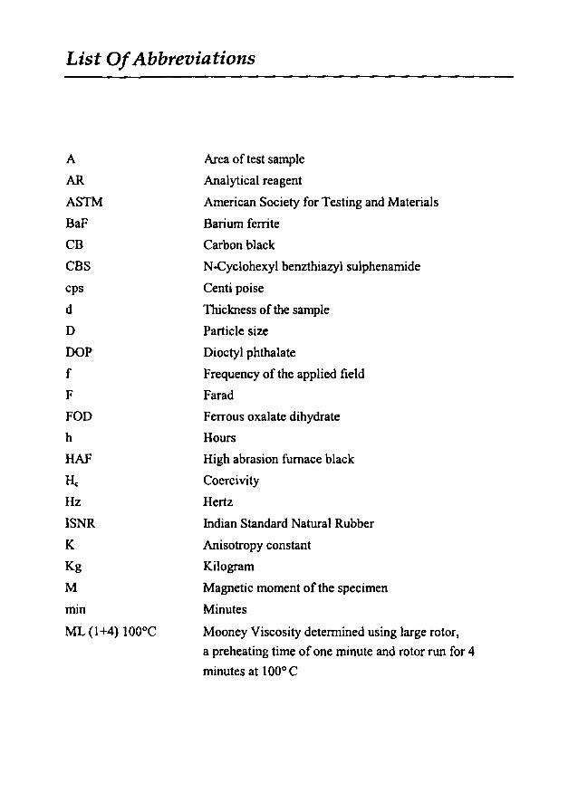
List OfAbbreviations
A
AR
ASTM
BaF
CB
cascps
d
D
DOP
f
F
FOD
h
HAF
He
Hz
ISNR
K
Kg
M
min
ML (1+4) 100°C
Area of test sample
Analytical reagent
American Society for Testing and Materials
Barium ferrite
Carbon black
N-Cyclohexyl benzthiazyl sulphenamide
Centi poise
Thickness of the sample
Particle size
Dioctyl phthalate
Frequency of the applied field
Farad
Ferrous oxalate dihydrate
Hours
High abrasion furnace black
Coercivity
Hertz
Indian Standard Natural Rubber
Anisotropy constant
Kilogram
Magnetic moment of the specimen
Minutes
Mooney Viscosity determined using large rotor,
a preheating time of one minute and rotor run for 4
minutes at 100° C

List ofAbbreviations
mm MilIimeter
MPa Mega Pascal
Mr Magnetic remanence or retentivity
Ms Saturation magnetisation
n Number of turns per unit length of coil
NBR Acrylonitrile butadiene rubber
nm Nano meter
Nm Newton meter
NR Natural rubber
Phr Parts per hundred rubber
RFC Rubber ferrite composite J
rpm Revolutions per minute
S Siemens
SrF Strontium ferrite
~o Optimum cure time
tlo Scorch time
ts Induction time
T Absolute temperature
UHF Ultra high frequency
UTM Universal testing machine
V Volume loss
VHF Very high frequency
VSM Vibrating sample magnetometer
XRD X-ray powder diffraction
ZnO Zinc Oxide
List o[Symbols
~
X.
Cand 9
P
M1
cc
E
tan 0
Relative permeability
Susceptibility
Curie Weiss constants.
Wavelength of the X-ray radiation
Full width half maximum of the intensity
Density of the sample
Mass loss
Magnetic flux
Permeability of free space
Geometric moment decided by position of
moment with respect to coil as well as shape of coil.
Dielectric constant
Relative permittivity
Permittivity of free space
Real part of dielectric permittivity
Imaginary part of the dielectric permittivity
Dielectric loss
ac conductivity
Angular frequency'
List ofPublications
1. M.A. Sotoman, M.R.Anantharaman and Philip Kurian, Processability and
Mechanical Properties of Rubber Ferrite Composites. National Seminar on
Current Trends in Macromolecular Chemistry and Technology- MACROSEM
2000, St. Albert's College, Ernakulam, August 23-25 (2000).
2. M.A.Soloman, M.R.Anantharaman and Philip Kurian, Dielectric Properties
of Rubber Ferrite Composites with and without Carbon Black. Proce.13lh
Kerala State Science Congress, KILA, Thrissur, January 29-31 (2001).
3. M.A.Soloman, P.A.Joy, M.R.Anantharaman and Philip Kurian,
Processability and Magnetic Properties of Rubber Ferrite Composites
containing Barium Ferrite, International Journal of Polymeric Materials.
(In press).
4. M.A.Soloman, M.R.Anantharaman and Philip Kurian, Dielectric and
Mechanical Properties of Rubber Ferrite Composites containing Barium
Ferrite, Progress in Rubber and Plastics Technology. (Accepted for
publication).
5. M.A.Soloman, M.R.Anantharaman and Philip Kurian, Effect of Carbon
Black on the Mechanical and Dielectric Properties of Rubber Ferrite
Composites containing Barium Ferrite, Plastics Rubber and Composites.
(Communicated).
6. M.A.Soloman, M.R.Anantharaman and Philip Kurian, Dielectric and
Processing Properties of Rubber Ferrite Composites containing Strontium
Ferrite, Journal of Elastomers and Plastics. (Communicated).
7. M.A.Soloman, P.AJoy, M.R.Anantharaman and Philip Kurian, Magnetic and
Mechanical Properties of Rubber Ferrite Composites containing Strontium
Ferrite, European Polymer Journal. (Communicated).


![A comparison study of polymer/cobalt ferrite nano ... and Ataie / Vol.48, No.2, December 2015 60 attention in the past few years [1, 2]. Particularly, polymer/magnetic ferrite nano-composites](https://img.pdfslide.net/doc/110x75/5aabb2e17f8b9a2e088c2943/a-comparison-study-of-polymercobalt-ferrite-nano-and-ataie-vol48-no2.jpg)