Embed Size (px)
Citation preview
NOTE: Please read all
instructions carefully before using this product
Table of Contents
Safety Notice
Hardware Pack
Assembly Instruction
Parts List
Warranty
Ordering Parts
Model NS-40501E
Retain This Manual for Reference
151104
ASSEMBLY &
OWNER'S MANUAL
Magnetic-Resistance Elliptical Exerciser
NS-40501E
IMPEX® INC.
2801 S. Towne Ave, Pomona, CA 91766 Tel: (800) 999-8899 Fax: (626) 961-9966
www.impex-fitness.com [email protected]
© IMPEX INC. www.impex-fitness.com 1
TABLE OF CONTENTS
BEFORE YOU BEGIN...................................................................................…. 1 IMPORTANT SAFETY NOTICES..................................................................…. 2
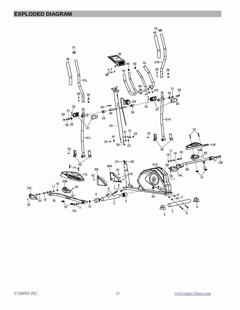
WARNING LABEL PLACEMENT………………………………………………….. 3 HARDWARE PACK …………………………………………………………………. 4 ASSEMBLY INSTRUCTIONS........................................................................…. 7 EXPLODED DIAGRAM………………………………………………………………. 15 PARTS LIST...................................................................................................…. 17
CARE, MAINTENANCE, AND STORAGE…………………………………………. 19 OPERATING NOTES………………………………………………………………… 19 COMPUTER…………………………………………………………………………… 20 EXERCISE GUIDELINES……………………………………………………………. 21
WARRANTY.................................................................................................……. 23 ORDERING PARTS.....................................................................................……. 23
BEFORE YOU BEGIN Thank you for selecting the MARCY Magnetic-Resistance Elliptical Exerciser NS-40501E by IMPEX® INC. For your safety and benefit, read this manual carefully before using the bike. As a manufacturer, we are committed to provide you complete customer satisfaction. If you have any questions, or find there are missing or damaged parts, we guarantee you complete satisfaction through direct assistance from our factory. To avoid unnecessary delays, please call our TOLL-FREE customer service number. Our Customer Service Agents will provide immediate assistance to you.
Toll-Free Customer Service Number 1-800-999-8899
Mon. - Fri. 9 a.m. - 5 p.m. PST www.impex-fitness.com
© IMPEX INC. www.impex-fitness.com 2
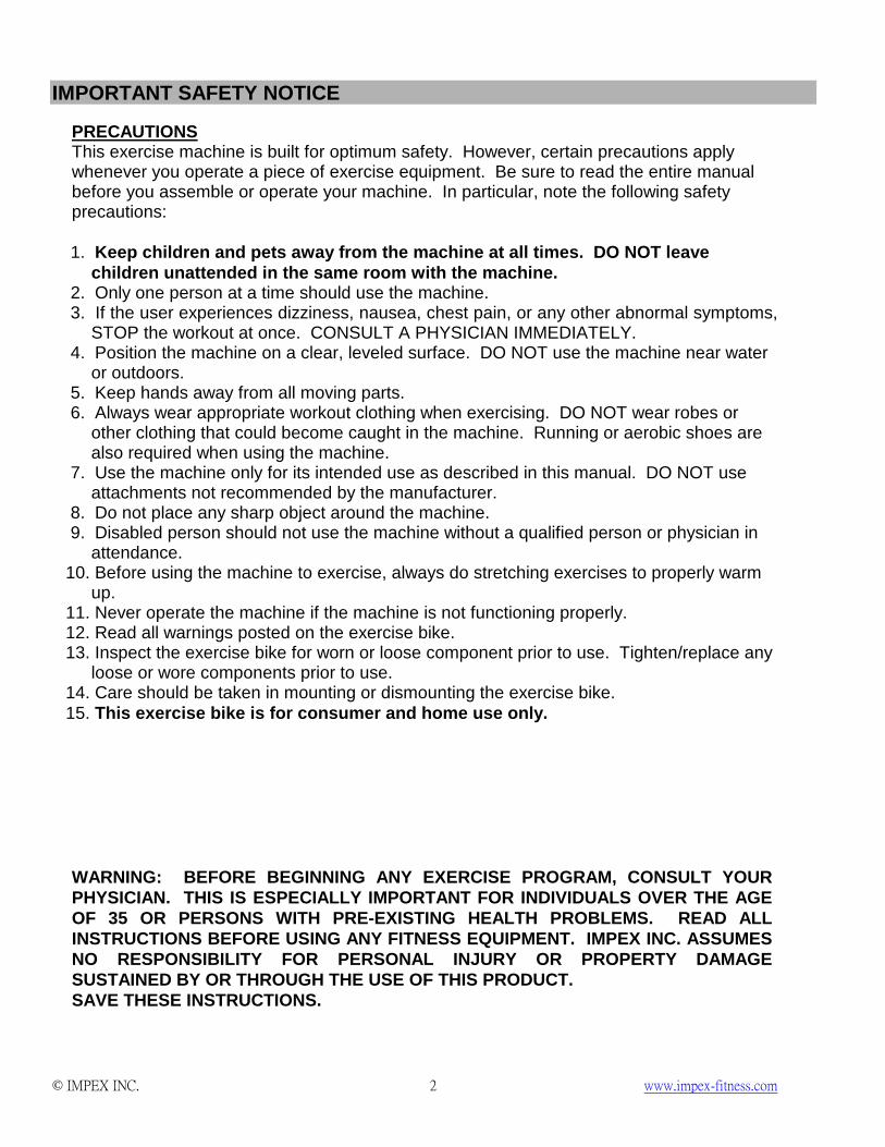
IMPORTANT SAFETY NOTICE
This exercise machine is built for optimum safety. However, certain precautions apply whenever you operate a piece of exercise equipment. Be sure to read the entire manual before you assemble or operate your machine. In particular, note the following safety precautions:
PRECAUTIONS
1. Keep children and pets away from the machine at all times. DO NOT leave
children unattended in the same room with the machine. 2. Only one person at a time should use the machine. 3. If the user experiences dizziness, nausea, chest pain, or any other abnormal symptoms,
STOP the workout at once. CONSULT A PHYSICIAN IMMEDIATELY. 4. Position the machine on a clear, leveled surface. DO NOT use the machine near water
or outdoors. 5. Keep hands away from all moving parts. 6. Always wear appropriate workout clothing when exercising. DO NOT wear robes or
other clothing that could become caught in the machine. Running or aerobic shoes are also required when using the machine.
7. Use the machine only for its intended use as described in this manual. DO NOT use attachments not recommended by the manufacturer.
8. Do not place any sharp object around the machine. 9. Disabled person should not use the machine without a qualified person or physician in
attendance. 10. Before using the machine to exercise, always do stretching exercises to properly warm
up. 11. Never operate the machine if the machine is not functioning properly. 12. Read all warnings posted on the exercise bike. 13. Inspect the exercise bike for worn or loose component prior to use. Tighten/replace any
loose or wore components prior to use. 14. Care should be taken in mounting or dismounting the exercise bike. 15. This exercise bike is for consumer and home use only.
WARNING: BEFORE BEGINNING ANY EXERCISE PROGRAM, CONSULT YOUR PHYSICIAN. THIS IS ESPECIALLY IMPORTANT FOR INDIVIDUALS OVER THE AGE OF 35 OR PERSONS WITH PRE-EXISTING HEALTH PROBLEMS. READ ALL INSTRUCTIONS BEFORE USING ANY FITNESS EQUIPMENT. IMPEX INC. ASSUMES NO RESPONSIBILITY FOR PERSONAL INJURY OR PROPERTY DAMAGE SUSTAINED BY OR THROUGH THE USE OF THIS PRODUCT. SAVE THESE INSTRUCTIONS.
© IMPEX INC. www.impex-fitness.com 3
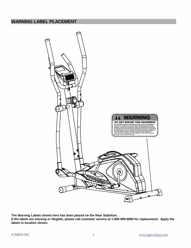
WARNING LABEL PLACEMENT
The Warning Labels shown here has been placed on the Rear Stabilizer. If the labels are missing or illegible, please call customer service at 1-800-999-8899 for replacement. Apply the labels in location shown.
© IMPEX INC. www.impex-fitness.com 4
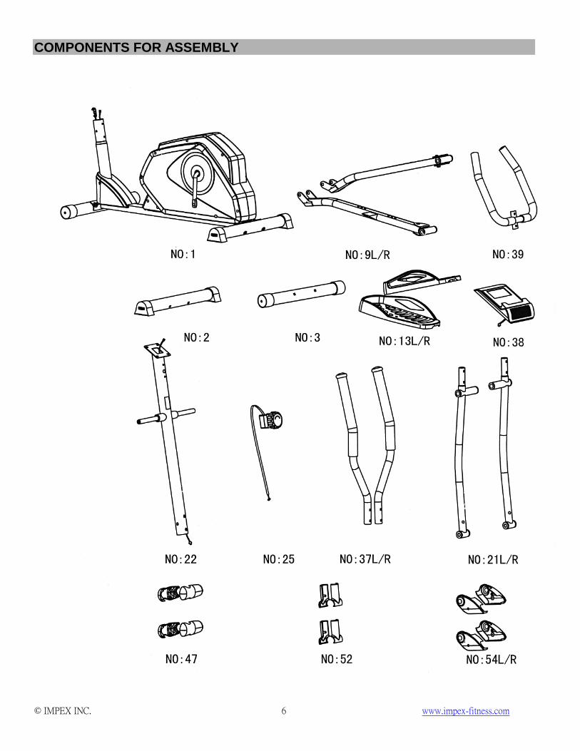
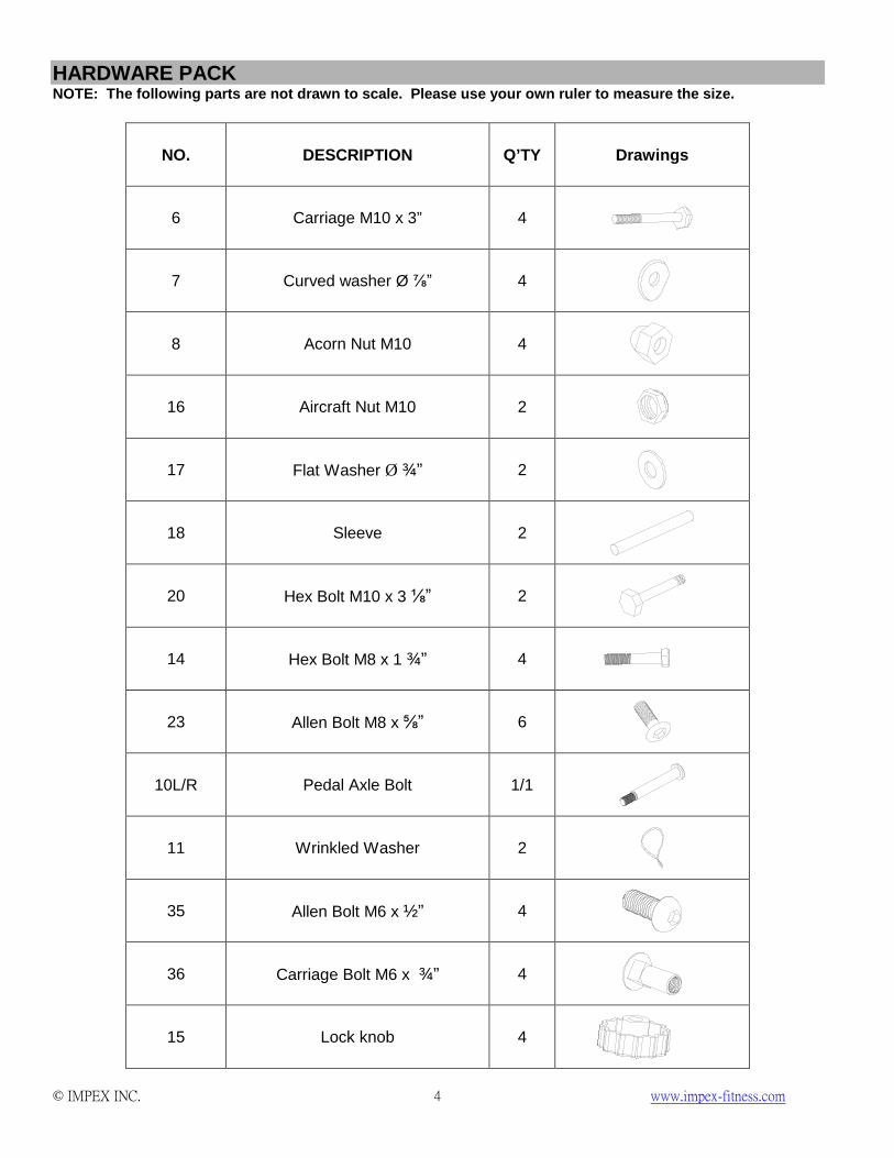
HARDWARE PACK NOTE: The following parts are not drawn to scale. Please use your own ruler to measure the size.
NO. DESCRIPTION Q’TY Drawings
6 Carriage M10 x 3” 4
7 Curved washer Ø ⅞” 4
8 Acorn Nut M10 4
16 Aircraft Nut M10 2
17 Flat Washer Ø ¾” 2
18 Sleeve 2
20 Hex Bolt M10 x 3 ⅛” 2
14 Hex Bolt M8 x 1 ¾” 4
23 Allen Bolt M8 x ⅝” 6
10L/R Pedal Axle Bolt 1/1
11 Wrinkled Washer 2
35 Allen Bolt M6 x ½” 4
36 Carriage Bolt M6 x ¾” 4
15 Lock knob 4
© IMPEX INC. www.impex-fitness.com 5
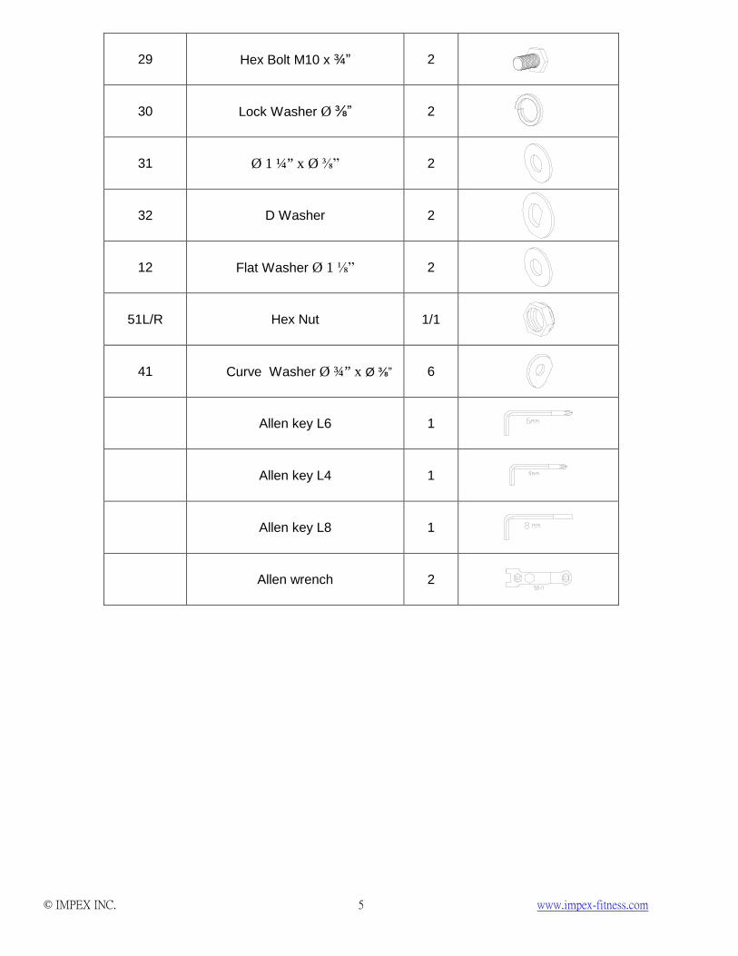
29 Hex Bolt M10 x ¾” 2
30 Lock Washer Ø ⅜” 2
31 Ø 1 ¼” x Ø ⅜” 2
32 D Washer 2
12 Flat Washer Ø 1 ⅛” 2
51L/R Hex Nut 1/1
41 Curve Washer Ø ¾” x Ø ⅜” 6
Allen key L6 1
Allen key L4 1
Allen key L8 1
Allen wrench 2
© IMPEX INC. www.impex-fitness.com 7
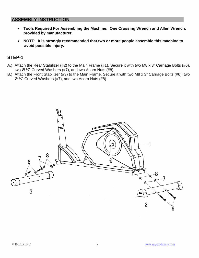
ASSEMBLY INSTRUCTION
• Tools Required For Assembling the Machine: One Crossing Wrench and Allen Wrench, provided by manufacturer.
• NOTE: It is strongly recommended that two or more people assemble this machine to avoid possible injury.
STEP-1
A.) Attach the Rear Stabilizer (#2) to the Main Frame (#1). Secure it with two M8 x 3” Carriage Bolts (#6), two Ø ⅞” Curved Washers (#7), and two Acorn Nuts (#8).
B.) Attach the Front Stabilizer (#3) to the Main Frame. Secure it with two M8 x 3” Carriage Bolts (#6), two Ø ⅞” Curved Washers (#7), and two Acorn Nuts (#8).
© IMPEX INC. www.impex-fitness.com 8
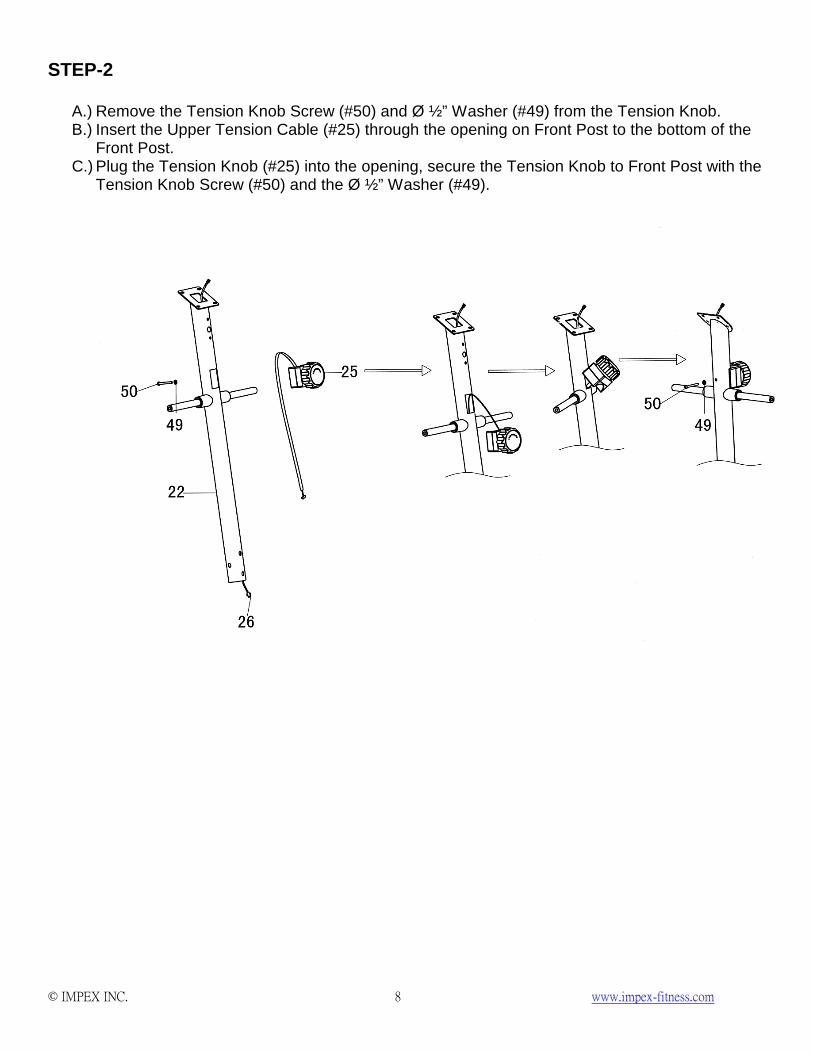
STEP-2
A.) Remove the Tension Knob Screw (#50) and Ø ½” Washer (#49) from the Tension Knob. B.) Insert the Upper Tension Cable (#25) through the opening on Front Post to the bottom of the
Front Post. C.) Plug the Tension Knob (#25) into the opening, secure the Tension Knob to Front Post with the
Tension Knob Screw (#50) and the Ø ½” Washer (#49).
© IMPEX INC. www.impex-fitness.com 9
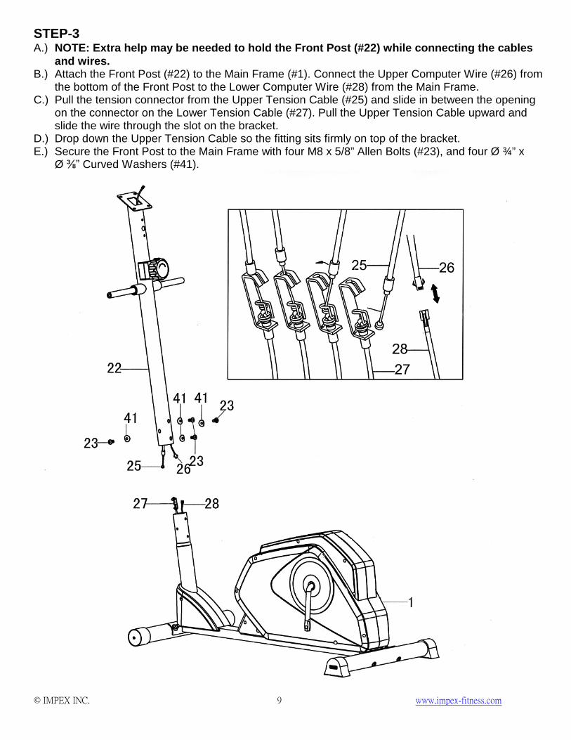
STEP-3 A.) NOTE: Extra help may be needed to hold the Front Post (#22) while connecting the cables
and wires. B.) Attach the Front Post (#22) to the Main Frame (#1). Connect the Upper Computer Wire (#26) from
the bottom of the Front Post to the Lower Computer Wire (#28) from the Main Frame. C.) Pull the tension connector from the Upper Tension Cable (#25) and slide in between the opening
on the connector on the Lower Tension Cable (#27). Pull the Upper Tension Cable upward and slide the wire through the slot on the bracket.
D.) Drop down the Upper Tension Cable so the fitting sits firmly on top of the bracket. E.) Secure the Front Post to the Main Frame with four M8 x 5/8” Allen Bolts (#23), and four Ø ¾” x
Ø ⅜” Curved Washers (#41).
© IMPEX INC. www.impex-fitness.com 10
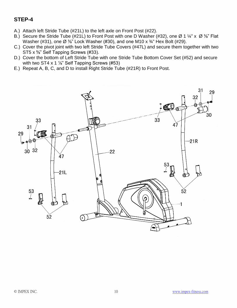
STEP-4 A.) Attach left Stride Tube (#21L) to the left axle on Front Post (#22). B.) Secure the Stride Tube (#21L) to Front Post with one D Washer (#32), one Ø 1 ¼” x Ø ⅜” Flat
Washer (#31), one Ø ⅜” Lock Washer (#30), and one M10 x ¾” Hex Bolt (#29). C.) Cover the pivot joint with two left Stride Tube Covers (#47L) and secure them together with two
ST5 x ⅝” Self Tapping Screws (#33). D.) Cover the bottom of Left Stride Tube with one Stride Tube Bottom Cover Set (#52) and secure
with two ST4 x 1 ⅛” Self Tapping Screws (#53) E.) Repeat A, B, C, and D to install Right Stride Tube (#21R) to Front Post.
© IMPEX INC. www.impex-fitness.com 11
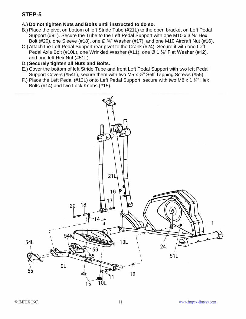
STEP-5 A.) Do not tighten Nuts and Bolts until instructed to do so. B.) Place the pivot on bottom of left Stride Tube (#21L) to the open bracket on Left Pedal
Support (#9L). Secure the Tube to the Left Pedal Support with one M10 x 3 ⅛” Hex Bolt (#20), one Sleeve (#18), one Ø ¾” Washer (#17), and one M10 Aircraft Nut (#16).
C.) Attach the Left Pedal Support rear pivot to the Crank (#24). Secure it with one Left Pedal Axle Bolt (#10L), one Wrinkled Washer (#11), one Ø 1 ⅛” Flat Washer (#12), and one left Hex Nut (#51L).
D.) Securely tighten all Nuts and Bolts. E.) Cover the bottom of left Stride Tube and front Left Pedal Support with two left Pedal
Support Covers (#54L), secure them with two M5 x ⅜” Self Tapping Screws (#55). F.) Place the Left Pedal (#13L) onto Left Pedal Support, secure with two M8 x 1 ¾” Hex
Bolts (#14) and two Lock Knobs (#15).
© IMPEX INC. www.impex-fitness.com 12
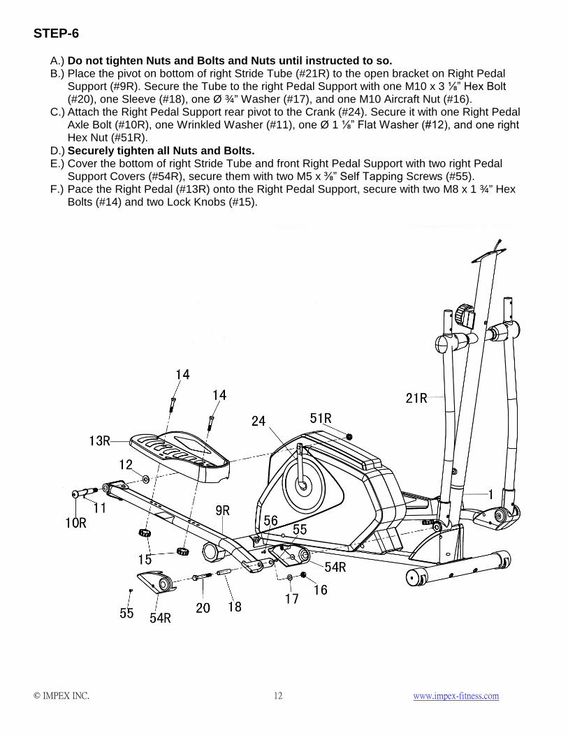
STEP-6
A.) Do not tighten Nuts and Bolts and Nuts until instructed to so. B.) Place the pivot on bottom of right Stride Tube (#21R) to the open bracket on Right Pedal
Support (#9R). Secure the Tube to the right Pedal Support with one M10 x 3 ⅛” Hex Bolt (#20), one Sleeve (#18), one Ø ¾” Washer (#17), and one M10 Aircraft Nut (#16).
C.) Attach the Right Pedal Support rear pivot to the Crank (#24). Secure it with one Right Pedal Axle Bolt (#10R), one Wrinkled Washer (#11), one Ø 1 ⅛” Flat Washer (#12), and one right Hex Nut (#51R).
D.) Securely tighten all Nuts and Bolts. E.) Cover the bottom of right Stride Tube and front Right Pedal Support with two right Pedal
Support Covers (#54R), secure them with two M5 x ⅜” Self Tapping Screws (#55). F.) Pace the Right Pedal (#13R) onto the Right Pedal Support, secure with two M8 x 1 ¾” Hex
Bolts (#14) and two Lock Knobs (#15).
© IMPEX INC. www.impex-fitness.com 13
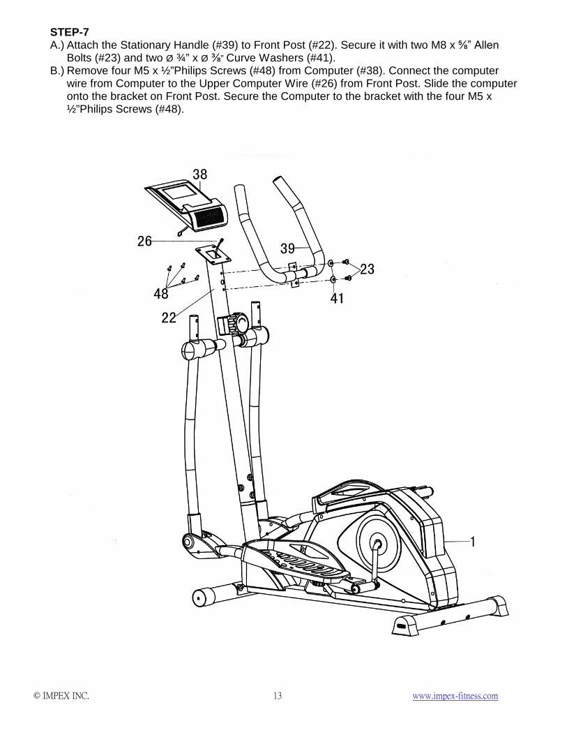
STEP-7 A.) Attach the Stationary Handle (#39) to Front Post (#22). Secure it with two M8 x ⅝” Allen
Bolts (#23) and two Ø ¾” x Ø ⅜” Curve Washers (#41). B.) Remove four M5 x ½”Philips Screws (#48) from Computer (#38). Connect the computer
wire from Computer to the Upper Computer Wire (#26) from Front Post. Slide the computer onto the bracket on Front Post. Secure the Computer to the bracket with the four M5 x ½”Philips Screws (#48).
© IMPEX INC. www.impex-fitness.com 14
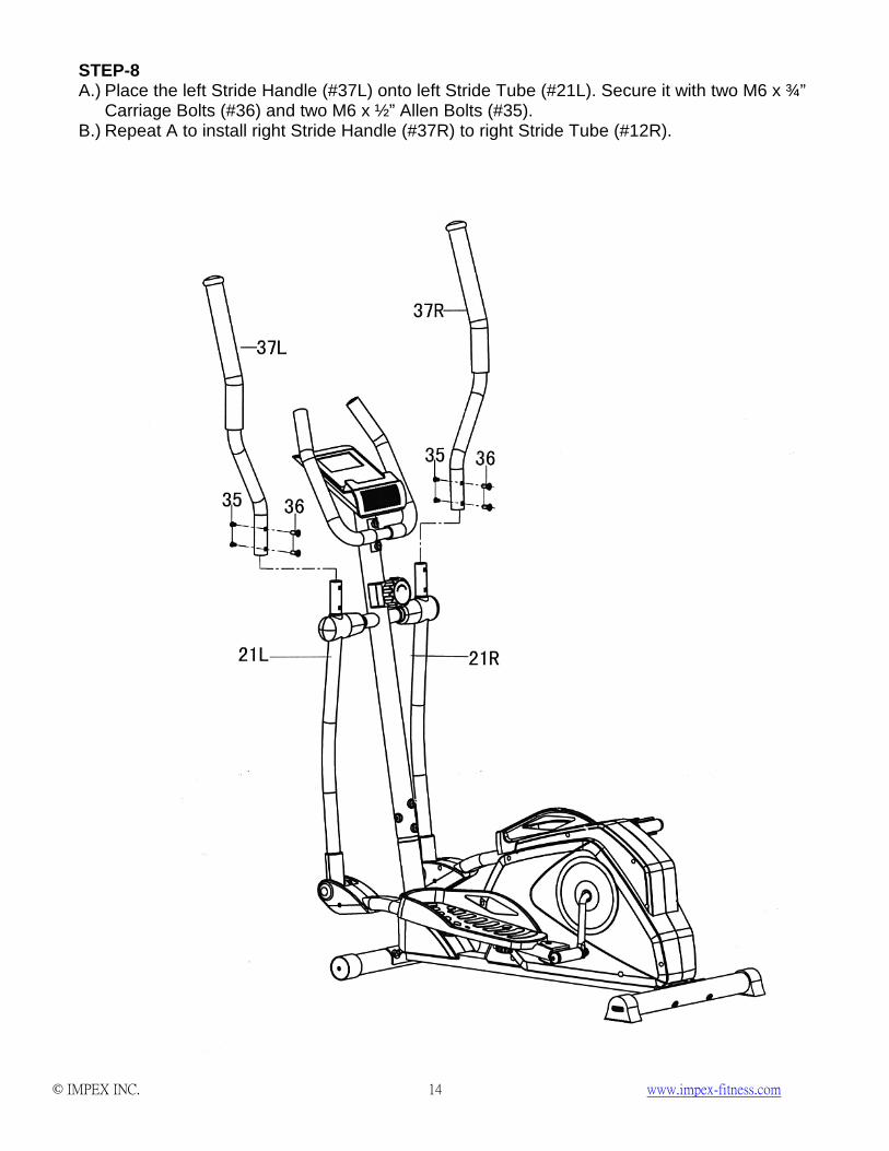
STEP-8 A.) Place the left Stride Handle (#37L) onto left Stride Tube (#21L). Secure it with two M6 x ¾”
Carriage Bolts (#36) and two M6 x ½” Allen Bolts (#35). B.) Repeat A to install right Stride Handle (#37R) to right Stride Tube (#12R).

© IMPEX INC. www.impex-fitness.com 17
NS-40501E PARTS LIST PART NO. DESCRIPTION SPEC. QUANTITY
1 Main Frame 1 2 Rear Stabilizer 1 3 Front Stabilizer 1 4 Rear Stabilizer End Cap 2 5 Front Stabilizer End Cap 2 6 Carriage Bolt M10 x 3” 4 7 Curve Washer Ø ⅞” 4 8 Acorn Nut M10 4
9L Left Pedal Support 1 9R Right Pedal Support 1 10L Left Pedal Axle Bolt 1 10R Right Pedal Axle Bolt 1 11 Wrinkled Washer 2 12 Flat Washer Ø 1 ⅛” 2
13L Left Pedal 1 13R Right Pedal 1 14 Hex Bolt M8 x 1 ¾” 4 15 Lock Knob 4 16 Aircraft Nut M10 2 17 Washer Ø ¾” 2 18 Sleeve 2 19 Upper Stride Handle End Cap 2 20 Hex Bolt M10 x 3 ⅛” 2
21L/R Stride Tube 1/1 22 Front Post 1 23 Allen Bolt M8 x ⅝” 6 24 Crank 1 25 Tension Knob/Upper Tension Cable 1 26 Upper Computer Wire 1 27 Lower Tension Cable 1 28 Lower Computer Wire 1 29 Hex Bolt M10 x ¾” 2 30 Lock Washer Ø ⅜” 2 31 Flat Washer Ø 1 ¼” x Ø ⅜” 2 32 D Washer 2 33 Self Tapping Screw ST5 x ⅝” 4 34 Plastic Spacer 2 35 Allen Bolt M6 x ½” 4 36 Carriage Bolt M6 x ¾” 4

© IMPEX INC. www.impex-fitness.com 18
37L/R Stride Handle 1/1 38 Computer 1 39 Stationary Handle 1 40 Stationary Handle End Cap Ø 1” 2 41 Curve Washer Ø ¾” Ø ⅜” 6 42 Counter Sunk Self Tapping Screw ST5 x ⅝” 2 43 Flat Self Tapping Screw ST5 x ⅝” 2 44 Stationary Handle Grip 2 45 Stride Handle Grip 2
46L/R Front Post Cover 1/1 47L/R Stride Tube Cover 2/2
48 Philips Screw M5 x ½” 4 49 Washer Ø ½” 1 50 Tension Knob Screw M5 x 1 ⅝” 1
51L/R Hex Nut 1/1 52 Stride Tube Bottom Cover Set 2 53 Self Tapping Screw ST4 x 1 ⅛” 4
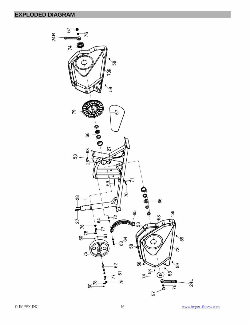
54L/R Pedal Support Cover 2/2 55 Philips Screw M5 x ⅜” 4 56 Self Tapping Screw ST4 x ⅝” 2 57 Hardware Pack 1 58 Button Head Self Tapping Screw ST5 x ⅝” 8 59 Flat Head Self Tapping Screw ST5 x ⅝” 4 60 Nylon Nut M6 2 61 Flywheel Axle Lock Washer 2 62 Flywheel Axle 1 63 Hex Bolt M8 x 4 ⅛: 1 64 Magnet Assembly Bushing 2 65 Magnet Assembly 1 66 Ball Bearing Set 1 67 Belt 1 68 Computer Wire Sensing Base 1 69 Magnet Assembly Spring 1 70 Hex Bolt M6 x 1” 1 71 Hex Nut M6 2 72 Nylon Nut M8 1 73 Main Frame Cover L/R 1/1 74 Crank End Cover 2 75 Flywheel 1 76 Flange Nut 2 77 Ring Bolt 2 78 Locking Clamp 2 79 Pulley with Axle 1
© IMPEX INC. www.impex-fitness.com 19
CARE, MAINTENANCE AND STORAGE 1. Inspect and tighten all parts each time you use the machine. Replace any worn parts
immediately. 2. The machine can be cleaned using a damp cloth and mild non-abrasive detergent. Do not use
solvents. 3. Store the bike IN-DOOR. Excess moisture and water would cause rust on the frame. 4. The Bike shall be placed at least 24 inches away from the wall or/and any other object such as
furniture to provide safe access to and passage around the machine. 5. To avoid possible injury, the help of two or more people are needed when moving the machine
around. 6. Disposal Instructions – The equipment can be safely disassembled and disposed without
unreasonable hazards. Call your local recycle agency regarding details of recycling. 7. The maximum user weight is 300 lbs. 8. Assembled Dimension: 49” x 24” x 64.25”
OPERATING NOTES
Tension Adjustment
Use the Tension Knob on Front Post to adjust the exercising resistance.
FOOT POSITIONING
Step with both feet on the two Pedals and hold the Stride Handles with two hands, and then start to exercise. NOTE: DO not stand on one Pedal with both feet, or just step one foot on one Pedal during exercise.
TRANSPORT
The Bike has a pair of roller wheels on Front Stabilizer End Cap. To move, carefully hold and tilt the machine, and roll.
© IMPEX INC. www.impex-fitness.com 20
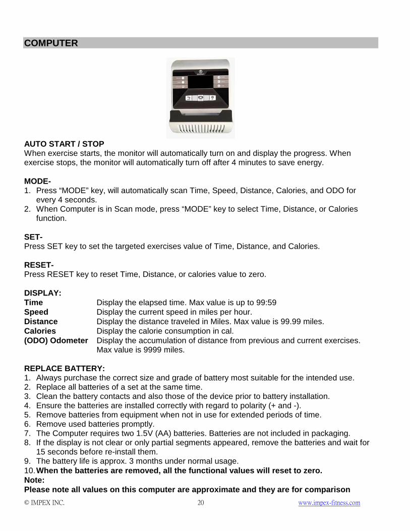
COMPUTER
AUTO START / STOP When exercise starts, the monitor will automatically turn on and display the progress. When exercise stops, the monitor will automatically turn off after 4 minutes to save energy. MODE- 1. Press “MODE” key, will automatically scan Time, Speed, Distance, Calories, and ODO for
every 4 seconds. 2. When Computer is in Scan mode, press “MODE” key to select Time, Distance, or Calories
function. SET- Press SET key to set the targeted exercises value of Time, Distance, and Calories. RESET- Press RESET key to reset Time, Distance, or calories value to zero. DISPLAY: Time Display the elapsed time. Max value is up to 99:59 Speed Display the current speed in miles per hour. Distance Display the distance traveled in Miles. Max value is 99.99 miles. Calories Display the calorie consumption in cal. (ODO) Odometer Display the accumulation of distance from previous and current exercises.
Max value is 9999 miles. REPLACE BATTERY: 1. Always purchase the correct size and grade of battery most suitable for the intended use. 2. Replace all batteries of a set at the same time. 3. Clean the battery contacts and also those of the device prior to battery installation. 4. Ensure the batteries are installed correctly with regard to polarity (+ and -). 5. Remove batteries from equipment when not in use for extended periods of time. 6. Remove used batteries promptly. 7. The Computer requires two 1.5V (AA) batteries. Batteries are not included in packaging. 8. If the display is not clear or only partial segments appeared, remove the batteries and wait for
15 seconds before re-install them. 9. The battery life is approx. 3 months under normal usage. 10. When the batteries are removed, all the functional values will reset to zero. Note: Please note all values on this computer are approximate and they are for comparison
© IMPEX INC. www.impex-fitness.com 21
purpose only. Do not use these values for any medical or rehabilitation purpose.
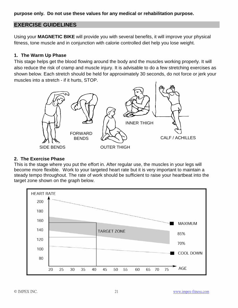
EXERCISE GUIDELINES Using your MAGNETIC BIKE will provide you with several benefits, it will improve your physical fitness, tone muscle and in conjunction with calorie controlled diet help you lose weight. 1. The Warm Up Phase This stage helps get the blood flowing around the body and the muscles working properly. It will also reduce the risk of cramp and muscle injury. It is advisable to do a few stretching exercises as shown below. Each stretch should be held for approximately 30 seconds, do not force or jerk your muscles into a stretch - if it hurts, STOP.
2. The Exercise Phase This is the stage where you put the effort in. After regular use, the muscles in your legs will become more flexible. Work to your targeted heart rate but it is very important to maintain a steady tempo throughout. The rate of work should be sufficient to raise your heartbeat into the target zone shown on the graph below.
SIDE BENDS OUTER THIGH
INNER THIGH
FORWARD BENDS CALF / ACHILLES
© IMPEX INC. www.impex-fitness.com 22
This stage should last for a minimum of 12 minutes though most people start at about 15-20 minutes
3. The Cool Down Phase
This stage is to let your Cardio-vascular System and muscles wind down. This is a repeat of the warm up exercise e.g. reduce your tempo, continue for approximately 5 minutes. The stretching exercises should now be repeated, again remembering not to force or jerk your muscles into the stretch. As you get fitter you may need to train longer and harder. It is advisable to train at least three times a week, and if possible space your workouts evenly throughout the week. MUSCLE TONING To tone muscle while on your MAGNETIC BIKE you will need to have the resistance set quite high. This will put more strain on our leg muscles and may mean you cannot train for as long as you would like. If you are also trying to improve your fitness you need to alter your training program. You should train as normal during the warm up and cool down phases, but towards the end of the exercise phase you should increase resistance making your legs work harder. You will have to reduce your speed to keep your heart rate in the target zone. WEIGHT LOSS The important factor here is the amount of effort you put in. The harder and longer you work the more calories you will burn. Effectively this is the same as if you were training to improve your fitness, the difference is the goal.

© IMPEX INC. www.impex-fitness.com 23
IMPEX® INC.
LIMITED WARRANTY
IMPEX Inc. ("IMPEX®") warrants this product to be free from defects in workmanship and material, under normal use and service conditions, for a period of two years on the Frame from the date of purchase. This warranty extends only to the original purchaser. IMPEX's obligation under this Warranty is limited to replacing or repairing, at IMPEX's option. All returns must be pre-authorized by IMPEX. Pre-authorization may be obtained by calling IMPEX Customer Service Department at 1-800-999-8899. All freights for products return to IMPEX must be prepaid by the customer. This warranty does not extend to any product or damage to a product caused by or attributable to freight damage, abuse, misuse, improper or abnormal usage or repairs not provided by an IMPEX authorized service center or for products used for commercial or rental purposes. No other warranty beyond that specifically set forth above is authorized by IMPEX. IMPEX is not responsible or liable for indirect, special or consequential damages arising out of or in connection with the use or performance of the product or other damages with respect to any economic loss, loss of property, loss of revenues or profits, loss of enjoyments or use, costs of removal, installation or other consequential damages or whatsoever natures. Some states do not allow the exclusion or limitation of incidental or consequential damages. Accordingly, the above limitation may not apply to you. The warranty extended hereunder is in lieu of any and all other warranties and any implied warranties of merchantability or fitness for a particular purpose is limited in its scope and duration to the terms set forth herein. Some states do not allow limitations on how long an implied warranty lasts. Accordingly, the above limitation may not apply to you. This warranty gives you specific legal right. You may also have other rights which vary from state to state. Register on-line www.impex-fitness.com
IMPEX® INC. 2801 S. Towne Ave. Pomona, CA 91766
ORDERING REPLACEMENT PARTS
Replacement parts can be ordered by calling our Customer Service Department toll-free at 1-800-999-8899 during our regular business hours: Monday through Friday, 9 am until 5 pm Pacific standard time. [email protected] When ordering replacement part, always give the following information. 1. Model 2. Description of Parts 3. Part Number 4. Date of Purchase
![EKF Estimation of Stride Width from Individual IMU-based ... · determining individual stride metrics (e.g. stride time, stride speed, foot clearance, stride length, etc.)[9][1],](https://img.pdfslide.net/doc/110x75/5ec0069b65be937c564c10bb/ekf-estimation-of-stride-width-from-individual-imu-based-determining-individual.jpg)