Embed Size (px)
Citation preview

Magnetic Separation of Fine Particles from Process Water Circuits in the Steel Industry
Mansour Saiepour, Tata Steel Group Environment, UK Martin Hubrich, VDEh-Betriebsforschungsinstitut GmbH (BFI), Germany
The European Conference on Sustainability, Energy & the Environment 2015 Official Conference Proceedings
Abstract Within a European collaborative research project aimed at reduction of fine iron-containing particles (0.5µm - 10µm) in steelmaking process water circuits, a new magnetic separation system using permanent magnets has been designed and tested. Hot rolling mill process water for descaling and cooling can accumulate large amounts of suspended solids that can cause spray nozzle wear (influencing product quality), erosion of equipment, clogging, lower performance and hence higher maintenance costs. Low quality water can also cause environmental issues by exceeding the regulatory limits, and higher water consumption from increased blowdown. Removal of these suspended solids is essential. This paper describes research undertaken at a Tata Steel site (UK) in collaboration with BFI (Germany) to develop a new magnetic separation system to efficiently remove the solids and produce sludge with low water content. Results of Computational Fluid Dynamics (CFD) simulations and site trials have been used to optimise the exact positions and number of magnets. Performance of the system was assessed by treating the mill process water. Flow rates of higher than 50m3/h, efficiencies greater than 98% and reduction of chemical dosing by 50% have been achieved. In comparison with a typical sand filter, the tested magnetic separator is more compact, produces sludge with 20 times more solids content with water content of only 0.06% of the treated flow compared to 1% -10% of conventional sand filters. Keywords: steel rolling mill water, steel surface cleaning water, process water, wastewater treatment, magnetic filtration
iafor The International Academic Forum
www.iafor.org

1. Introduction During iron and steelmaking processes, scale and iron particles down to 0.5 µm may be formed, entering the cooling and cleaning water systems with flows between 100 m³/h and 10,000 m³/h [1, 2 - 14]. In EU 28 there were approximately 169 million tonnes hot rolled steel produced in 2014 [15]. Up to 1% of the steel charged is transformed into scale, including approximately one-fourth as fine scale (< 40 µm) which has to be removed and is hence lost from production [2]. Typical hot rolling mill process water for descaling and cooling can accumulate large amounts of suspended solids that can cause spray nozzle wear (influencing product quality), erosion of equipment, clogging, lower process performance and hence higher maintenance costs. The removal of these suspended solids is essential to improve the product quality and process performance, and reduce costs. Contaminated water can also cause environmental issues by exceeding the regulatory limits, and higher water consumption from increased blowdown. Increasingly demanding national and European policy and legislation such as the EU Water Framework Directive [16], and Industrial Emissions Directive [17], have made it essential to manage and reduce the emissions to water to comply with environmental legislation. The contaminated process water is normally treated using a clarifier system (settlement tank) with the addition of chemicals to enhance the solids sedimentation rate. This treatment method can be inefficient and expensive to maintain, providing the opportunity for significant efficiency and financial gains as well as environmental improvement. Tata Steel continuously aim at increasing product quality, process efficiency and environmental improvement. As part of a European multi-partner research project, MAGSEP [18] started in July 2012, aimed at the reduction of fine iron-containing particles (0.5µm - 10µm) in steelmaking process water circuits, Tata Steel have collaborated with BFI (Germany) to develop a new magnetic separation system for treating process water. The aim of the project is the efficient and chemical-free removal of iron particles from process waters using strong field permanent magnets in combination with compact design and low back flush flows under 1 % of the treated water. Laboratory and on-site tests, and CFD-simulations are used for the development of a mobile plant with suitable magnet configurations for the efficient iron particle removal at different process water conditions. The project also aims at conditioning and metallurgical reuse (sinter plant, blast furnace) of the separated particles. This paper describes the research undertaken at a Tata Steel site (UK) to develop a new magnetic separation system to efficiently remove the suspended solids from hot rolling mill descaling (Scarfer) water and produce sludge with low water content. 1.1 Steel Surface Treatment Process Water Description The research was conducted at a Tata Steel site (UK), that produces alloyed steels for the Oil, Gas and Aerospace industries, on a steel billet mill surface treatment (scarfer) plant where oxy-propane flame is used to burn off the surface defects up to a depth of 3 mm. This process is immediately followed by a high pressure water jet to quench and clean the billet surface. The particulate emissions produced by the scarfing process are extracted and passed through an electrostatic precipitator (ESP) to filter the dust particles and allow clean air to be released to the atmosphere. The ESP collection plates are periodically cleaned with a water jet to maintain high performance.

During the scarfing process and cleaning of the ESP solid particles are introduced into the process water circuit. The water circuit consists of a hydrocyclone for the separation of coarse particles, followed by a buffer tank (clear well), Figure 1. The process water is pumped (discontinuously) towards a settlement tank (linear clarifier) with a flow rate of approximately 540 m³/h. The water is pumped on average for 40 minutes per hour. The scarfing process is operational for 5 days per week. A chemical (flocculant-coagulant) mixture is dosed at the inlet of the settlement tank to aid the sedimentation of the solid particles. Depending on the water levels some of the settlement tank water is discharged to a nearby hot rolling mill cooling water clarifier and replaced by make up water from a local river. Approximately 10 tonnes of sludge per week are removed with a grabber out of the settlement tank. Furthermore, the settlement tank is drained and cleaned once per year.
Figure 1 (a)

Figure 1 (b)
Figure 1: Tata Steel scarfer water circuit schematic (a) and settlement tank (b) 1.2 Required Improvements in Product, Process and Environment Experience has shown that an increase in the suspended solids concentration of a typical scarfer process water can have a significant effect on process performance and product quality. The solids can cause wear of scarfer spray nozzles, which can influence the quenching and cleaning of the product surface. The solids can also cause wear of ESP plates spray nozzles which will influence the ESP efficiency in reducing particulate emissions. The deterioration of process performance and product quality, and environmental issues lead to increased costs of repair and maintenance. The above scarfer water may have concentrations of up to 350 mg/l that should be reduced to below the process quality and environmental limits of 30 mg/l using the settlement tank, Figure 1. Owing to the variability of the process conditions and the need for a high solids removal efficiency the settlement tank is currently inadequate and expensive to maintain, providing the opportunity for significant efficiency and financial gains. Tata Steel UK decided to be a partner member in a collaborative project, MAGSEP, to look into improving the environmental impact and making savings through lowering costs of water operations by developing a magnetic separator to significantly reduce the suspended solids concentrations in the scarfer water system. Table 1 lists the desired improvements and performance requirements of particle separator at the Tata Steel scarfer water system.

Table 1: Requirements of particle separator at Tata Steel scarfer water system
1.3 Magnetic Separation Technologies Magnetic separation is preferred to other filtration techniques, such as sand filters, due to its: • lower operating costs – no consumables or chemicals, less flushing water, • higher separation efficiency including fine particles down to 0.5 µm, • reduced space requirement.
Generally the requirements for the process water are suspended solids concentration below 30 mg/l for hot rolling [5] and 50 mg/l for descaling pumps, with particle sizes below 50 µm [9]. Furthermore, in some cases for continuous casting cooling water particle sizes below 50 µm are required [11]. BFI had already developed a magnetic laboratory-based plant with a design flow rate of 4.5 m³/h and maximum flow of 10 m³/h . The magnets are placed in non-magnetic steel protection tubes. The magnets can be moved in and out of the protection tubes by a hydraulic unit. Furthermore, a nozzle system is installed at the top of the tank for cleaning of the protection tubes and further nozzles at the bottom of the tank for the removal of the separated particles after cleaning the magnets. The duration of the water spraying time for cleaning the protection tubes depends on the oil content of process water, generally below 15 minutes. Figure 2 and Table 2 present a comparison of the BFI Lab magnetic separator and conventional magnetic separators. The BFI Lab magnetic separator consists of five lines of permanent magnets alternately offset to ensure that the particles are positioned in the range of the magnetic field and impact the magnets directly because of their inertia. The positioning of magnets and hydrodynamic conditions in the BFI Lab magnetic separator can be adapted to the process water properties such as solids concentration and particle size. The chain magnetic separator (Patent DE 4130421 A1), Figure 2b, consists of only one line of magnets, decreasing the probability of the particles getting close enough to the magnet to be caught by the magnetic field and impact the magnet surface. The main distinguishing factors between the BFI Lab magnetic separator and the chain magnetic separator are the hydrodynamic conditions (laminar/turbulent) and the positioning of the magnets. A further magnetic separator with permanent magnets is based on a combination of a hydrocyclone with magnetic bars arranged along the main flow direction, Figure 2c. The main difference between the systems is the positioning of the magnets and the cleaning. The magnets are arranged in ten lines, but not shifted in position, so the probability of high particle capture is significantly lower compared to the BFI Lab magnetic separator. A further distinguishing mark is the magnet cleaning procedure, which takes place by stopping the flow, moving out the magnets and blowing in compressed air to create turbulent conditions inside the

hydrocyclone. After this, the hydrocyclone is emptied. The described cleaning method requires compressed air (operational costs). The high gradient magnetic separator (Patent WO 002002081092A), Figure 2d, consists of a tube with a wire cloth (several mesh layers) or steel wool inlet. It is apparent that at the inlet there is a risk of clogging from presence of oil in the process water. The cleaning is practiced by switching off/turning the magnets followed by high pressure back flushing. Trials with water from hot rolling mill or a descaling unit containing 300 mg/l solids, leading to a required cleaning water amount of 7.5% of the treated volume. At a solids content of 90 mg/l, the required cleaning water amount was 2.5% of treated volume. The back flushing time was 14 s [19]. The reported maximum flow rate was 650 m³/h [20].
a) BFI Lab magnetic separator b) Chain magnetic separator
c) Hydrocyclone mag separator d) High gradient mag separator
Figure 2: Schematics of the BFI lab and other magnetic separators

Table 2: Comparison of BFI lab and conventional magnetic separators
2. Preliminary Research for Optimization of Design of New Mobile Magnetic Separator To optimise the design of the new magnetic separation mobile plant all the necessary data and information related to the site application had to be collected. The information included the operating conditions, water sampling and analysis of the scarfer process water, and characteristics of the suspended solids. Additionally, it was necessary to carry out field tests using the existing BFI laboratory magnetic separator at the Tata Steel site scarfer water circuit to obtain essential information on the site implementation requirements and to prevent difficulties with implementation of the new 50 m3/h mobile magnetic separator. Specifically, the optimum flow rate for maximum removal efficiency and removal rate, magnet cleaning procedure for minimum duration and water use and sludge water content, and minimising chemical dosage have been investigated. Also, results of CFD simulations were used by BFI to complement the site trials to determine the exact positions and number of magnets in the new magnetic separator. 2.1 Scarfer Water Sampling and Analysis Several water sampling campaigns were undertaken at the Tata Steel settlement tank inlet and outlet to determine the water conditions that the magnetic separator will be

required to perform under. Figure 3 shows typical variations of the solids concentrations before water treatment during Sept-Nov 2012. Table 3 shows maximum, minimum and average values for particle concentration, size and composition for different periods in Dec 2012 to Oct 2013. Although, the particle composition analysis showed a highest iron content of 57.5%, it can be more than 80%, which makes it highly susceptible to magnetic attraction.
Figure 3: Solids concentrations in scarfer process water before treatment
Table 3: Range of particle concentrations, sizes and compositions in scarfer water

2.2 Field Tests with the BFI Laboratory Magnetic Separator The main aims of the on-site field tests were to: 1) investigate specific requirements and to prevent practical difficulties during future trials, 2) obtain data/information for optimum design of the new magnetic separator. The BFI Lab magnetic separator consists of 5 lines of 4 magnets each. The magnets are alternately shifted in position to maximise the attraction of particles. The scarfer water conditions have been described in sections 1.1, 1.2 and 2.1. The duration of the field trials was two weeks, and the magnetic separator was operated in parallel with the scarfer water settlement tank to investigate: • optimum flow rate for maximum removal efficiency and solids removal rate, • suitable cleaning procedure for minimum duration, water use, and sludge water content, • influence of chemical addition on performance of magnetic separation. Figure 4 shows the arrangement of the trial set up within the scarfer water system (a) and a photograph of the BFI Lab magnetic separator (b).
Figure 4 (a)
Figure 4 (b) Figure 4: Trials arrangement of the BFI lab magnetic separator
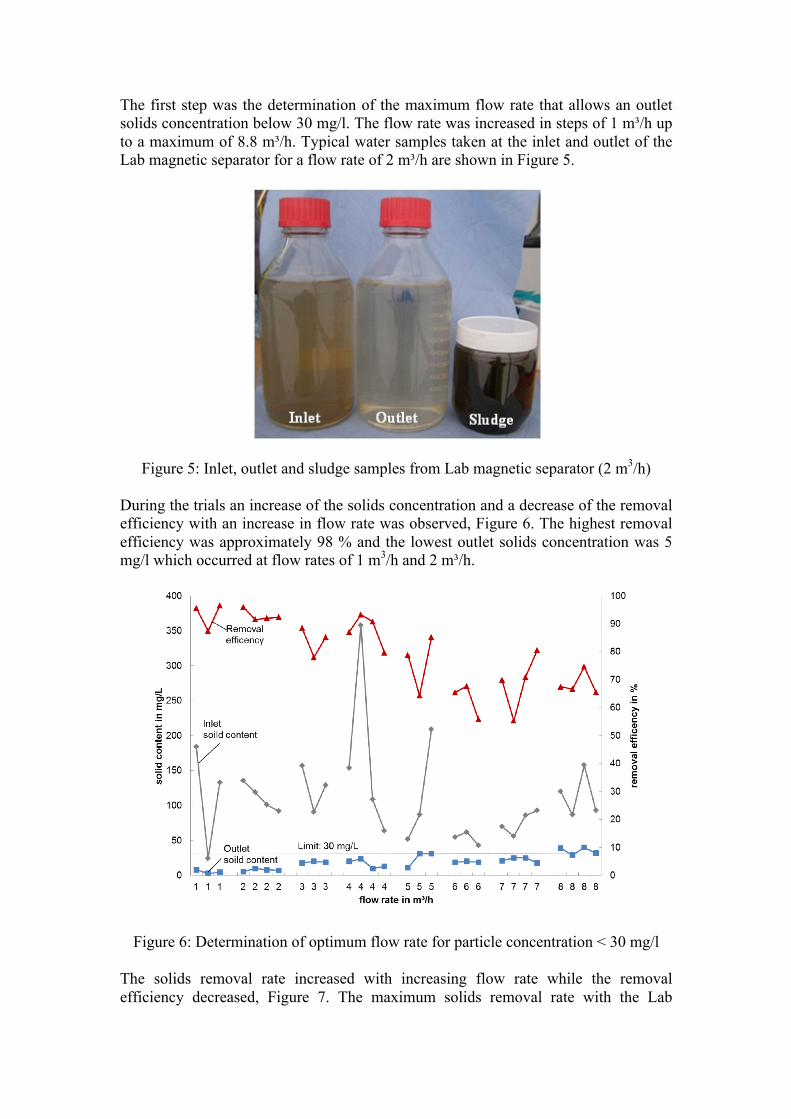
The first step was the determination of the maximum flow rate that allows an outlet solids concentration below 30 mg/l. The flow rate was increased in steps of 1 m³/h up to a maximum of 8.8 m³/h. Typical water samples taken at the inlet and outlet of the Lab magnetic separator for a flow rate of 2 m³/h are shown in Figure 5.
Figure 5: Inlet, outlet and sludge samples from Lab magnetic separator (2 m3/h) During the trials an increase of the solids concentration and a decrease of the removal efficiency with an increase in flow rate was observed, Figure 6. The highest removal efficiency was approximately 98 % and the lowest outlet solids concentration was 5 mg/l which occurred at flow rates of 1 m3/h and 2 m³/h.
Figure 6: Determination of optimum flow rate for particle concentration < 30 mg/l The solids removal rate increased with increasing flow rate while the removal efficiency decreased, Figure 7. The maximum solids removal rate with the Lab

magnetic separator was approximately 612 g/h, but the solids concentration after treatment (outlet) was on average 35 mg/l which is above the 30 mg/l limit. The optimum flow rate to achieve a combination of high solids removal rate (> 400 g/h) and the required outlet solids concentration could be reached at a flow rate of 7 m³/h (solids removal rate: 540 g/h, removal efficiency: 70%). These values formed the basis of the calculations of the application of the mobile plant for treatment of the scarfer process water.
Figure 7: Variation of solids removal rate with flow rate of Lab magnetic separator Furthermore, the influence of chemical addition at the inlet of the settlement tank and to the magnetic separator was investigated. The absence of chemical dosing leads to higher magnetic separator inlet solids concentration, approximately 200 mg/l (150 - 250 mg/l) compared to periods with chemical dosage with an average solids concentration approximately 120 mg/l (30 - 350 mg/l). Furthermore, an increase in the colouring and turbidity of the water was noticeable when chemical dosing was absent, Figure 8.

Figure 8: Comparison of inlet and outlet samples of the lab magnetic separator with and without chemical dosing at different flow rates
The trials without chemical dosing demonstrated, that it was possible to remove particles to achieve levels at the outlet below the limit of 30 mg/l at a maximum flow rate of 2 m³/h with a range of outlet solids concentration from 10 mg/l to 21 mg/l (average 18 mg/l), Figure 9.
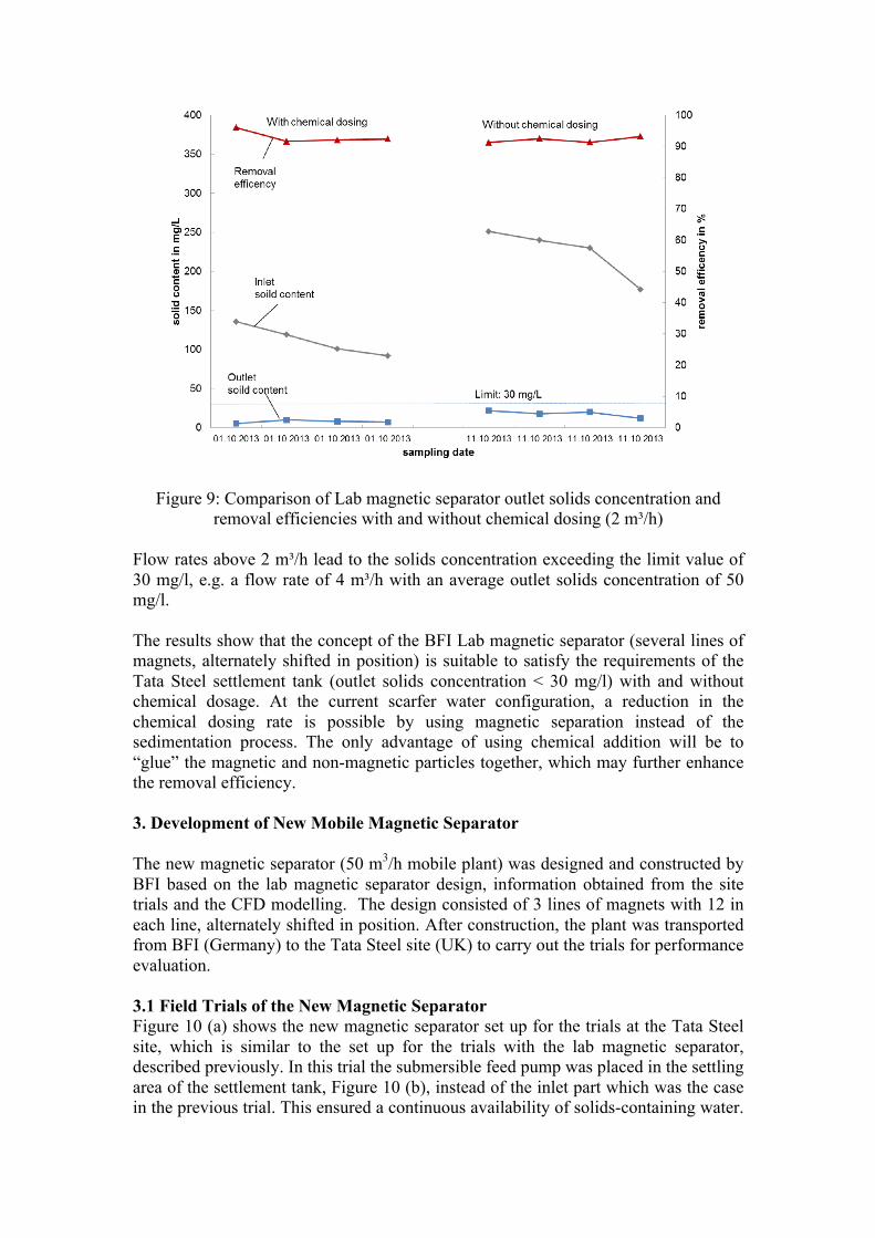
Figure 9: Comparison of Lab magnetic separator outlet solids concentration and removal efficiencies with and without chemical dosing (2 m³/h)
Flow rates above 2 m³/h lead to the solids concentration exceeding the limit value of 30 mg/l, e.g. a flow rate of 4 m³/h with an average outlet solids concentration of 50 mg/l. The results show that the concept of the BFI Lab magnetic separator (several lines of magnets, alternately shifted in position) is suitable to satisfy the requirements of the Tata Steel settlement tank (outlet solids concentration < 30 mg/l) with and without chemical dosage. At the current scarfer water configuration, a reduction in the chemical dosing rate is possible by using magnetic separation instead of the sedimentation process. The only advantage of using chemical addition will be to “glue” the magnetic and non-magnetic particles together, which may further enhance the removal efficiency. 3. Development of New Mobile Magnetic Separator The new magnetic separator (50 m3/h mobile plant) was designed and constructed by BFI based on the lab magnetic separator design, information obtained from the site trials and the CFD modelling. The design consisted of 3 lines of magnets with 12 in each line, alternately shifted in position. After construction, the plant was transported from BFI (Germany) to the Tata Steel site (UK) to carry out the trials for performance evaluation. 3.1 Field Trials of the New Magnetic Separator Figure 10 (a) shows the new magnetic separator set up for the trials at the Tata Steel site, which is similar to the set up for the trials with the lab magnetic separator, described previously. In this trial the submersible feed pump was placed in the settling area of the settlement tank, Figure 10 (b), instead of the inlet part which was the case in the previous trial. This ensured a continuous availability of solids-containing water.
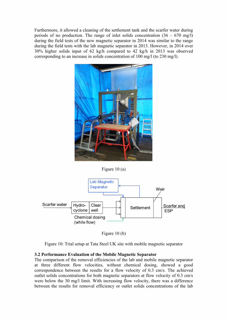
Furthermore, it allowed a cleaning of the settlement tank and the scarfer water during periods of no production. The range of inlet solids concentration (36 – 670 mg/l) during the field tests of the new magnetic separator in 2014 was similar to the range during the field tests with the lab magnetic separator in 2013. However, in 2014 over 30% higher solids input of 62 kg/h compared to 42 kg/h in 2013 was observed corresponding to an increase in solids concentration of 100 mg/l (to 230 mg/l).
Figure 10 (a)
Figure 10 (b)
Figure 10: Trial setup at Tata Steel UK site with mobile magnetic separator 3.2 Performance Evaluation of the Mobile Magnetic Separator The comparison of the removal efficiencies of the lab and mobile magnetic separator at three different flow velocities, without chemical dosing, showed a good correspondence between the results for a flow velocity of 0.3 cm/s. The achieved outlet solids concentrations for both magnetic separators at flow velocity of 0.3 cm/s were below the 30 mg/l limit. With increasing flow velocity, there was a difference between the results for removal efficiency or outlet solids concentrations of the lab

magnetic separator and the mobile magnetic separator, Figure 11. One reason for the decrease in efficiency of the mobile magnetic separator may be the reduced number of magnet lines (lab: 5 lines, mobile: 3 lines) as more magnet lines may allow more particles to be captured. A further reason may be the amount of non-magnetic particles present during the 2014 trials.
Figure 11: Comparison of outlet solids concentrations and removal efficiencies of BFI
lab and mobile magnetic separators without chemical dosage The long term behaviour of the mobile magnetic separator under operational conditions (varying particle concentrations, flow rates and processed steels) in Tata Steel water circuit has been investigated. During these field tests a total water of 2500 m³ has been treated in a period of two weeks. In the first part of the work at Tata Steel, the influence of different chemical dosage rates on the removal efficiency and outlet solids concentrations of the mobile magnetic separator were investigated. Dosing rates of 0%, 25%, 50%, 75%, and 100% of the rate normally applied at the settlement tank were used. Figure 12 and Figure 13 show that, for the exemplary flow rates of 10 m³/h and 50 m³/h, a chemical dosage rate of 25% of normal leads to a decrease of the outlet solids concentrations below the 30 mg/l limit. A further increase of the polymer dosage did not lead to a further decrease of the outlet solids concentrations. At the flow rate of 50 m³/h it was possible to reduce chemical dosing by 50%, achieve 85% efficiency and outlet solids concentrations below the 30 mg/l.

Figure 12: Influence of chemical dosage on outlet solids concentrations and removal efficiency (10 m³/h)
Figure 13: Influence of chemical dosage on outlet solids concentrations and removal efficiency (50 m³/h)
The magnet cleaning performance and suitable cleaning conditions were evaluated mainly by varying the cleaning water pressure between 1 bar to 7 bar and cleaning water spray duration. During the cleaning process, the movement of the nozzle holder and the cleaning water flow were stopped to observe the achieved cleaning efficiency. The following optimum cleaning conditions have been determined for the cases of 0% to 100% chemical dosage: • Required water pressure:

o 2 bar with 0% chemical dosage o 4 bar with 100% chemical dosage
• Water spray duration: 1 minute • Magnets maximum sludge loading capacity:140 kg (Figure 14) • Ratio of produced sludge/treated volume: 0.06%, e.g. 0.12 m³ sludge after treating 200 m³ • Solids content in sludge: 12 – 17 wt.-% - (sand filter: < 0.7 wt.-%) The dosage of chemical required an increase of the cleaning water pressure from 2 bar to 4 bar to ensure a sufficient magnet cleaning. Higher water pressure above 4 bar did not improve the magnet cleanness but increased the cleaning water consumption. The complete cleaning process consists of emptying/filling the tank of the magnetic separator, movement of the nozzle holder and water spraying for a total duration of < 5 min.
Figure 14 (a): Completely loaded magnets
Figure 14 (b): Magnets after cleaning
Figure 14: Magnets completely covered and after cleaning The performed field tests at Tata Steel site indicated that the developed magnetic separation design provides a suitable treatment process. It has the advantages of low

sludge amount with 0.06% of the treated volume, high sludge solids contents up to 17 wt.-%, low fresh water consumption and short cleaning periods (< 5 min), Table 4. Scaling of the magnets (protection tubes) in the tank or wear of the valves and nozzles could not be observed after treating 2,500 m³. Table 4: Summary of results of field trials with mobile magnetic separator
3.3 Water Quality and Economic Considerations An estimate of amount of water quality improvement at the Tata Steel scarfer water using the magnetic separator has been calculated, Table 5. Assuming an average settlement tank efficiency of 60%, average continuous flow of 300 m3/h (discontinuously at 540 m3/h), with magnetic separator efficiency of 95% and flow rates of 50 m3/h, 100 m3/h and 300 m3/h, the overall scarfer water treatment efficiency can increase to 66%, 72% and 95% respectively. Table 5: Estimated efficiency improvement of scarfer water treatment
The exact cost values of running the Tata Steel scarfer water system were not available, hence approximate cost savings have been estimated. Based on 50% reduction in chemical dosing and 20% water quality improvement approximately 42 k€/a cost reduction may be achieved, Table 6.

Table 6: Estimated potential costs savings using the magnetic separator
4. Conclusions Typical hot steel rolling process water can accumulate large amounts of suspended solids which influence the product and process quality leading to higher costs, and environmental concerns. Removal of these suspended solids is essential. The results of the BFI lab magnetic separator field trials at the Tata Steel UK site with no chemical dosing showed a maximum removal efficiency of 98 % and lowest outlet solids concentration of 5 mg/l, which occurred at a flow rate of 2 m³/h. The removal efficiency was approximately 70 % and outlet solids concentration <30 mg/l at a flow rate of 7 m³/h. The results of assessment of the mobile magnetic separator showed that at a flow rate of 10 m3/h with 25% dosing an efficiency of 98% and outlet solids concentration of 5 mg/l could be achieved. At flow rate of 50 m3/h with 50% dosing an efficiency of 85% and outlet solids concentration of 10 mg/l were achieved. The field trials illustrated the importance of an efficient magnet cleaning procedure. A low magnet cleaning water consumption (< 120 litres per cleaning) and short cleaning duration (water spray: 1 min, total: 5 min including movement of the nozzle holders, emptying/refilling the tank) could be confirmed. In comparison with a typical sand filter, the new mobile magnetic separator produces sludge with water content of only 0.06% of the treated volume compared to 1% -10% of conventional sand filters leading to significantly lower amounts for dewatering costs. The research results showed that the BFI magnetic separation design using permanent magnets is a promising technology for the removal of particles from the process water circuits with potential for quality improvement, cost savings and environmental benefit.

Acknowledgements The research leading to these results has received funding from the European Union Research Programme of the Research Fund for Coal and Steel (Contract number: RFSR-CT-2012-00042).

References [1] Continuous Water Treatment Process Collects and Filters Mill Scale at Outokumpu Stainless. Metal Producing & Processing 43.6 (2005): 25. [2] Reitmeyer, D, and G Diem. Neue Hochleistungs-Zunderseparation Im Kühlwasser-Recycling Bei Den Badischen Stahlwerken. Eisen und Stahl 125.10 (2005). [3] Beck, D.H. Scale basin design criteria for effective mill scale and oil removal. 2003 AISE Annual Convention and Exposition, Assoc. of Iron & Steel Engineers, Pittsburgh, US, (2003). [4] Amendola, G.; et al. Upgrade to process water treatment system for hot end operations at ArcelorMittal Indiana Harbour West. AISTech 2008, Iron and Steel Technology Conference , AIST; Proceedings, Vol. 1, Pittsburgh, US, (2008). [5] House, M. A new water treatment plant that guarantees superior water quality. AISTech 2008, Iron and Steel Technology Conference, AIST; Proceedings, Vol. 1, Pittsburgh, US, (2008). [6] Diaz, O., & House, M. (2007). New water treatment plant improves operations at Siderúrgica Añon. Steel Times International, 31(4), 56. [7] Allhands, M. N. (2004). New Style Automatic Self-Cleaning Filters for Mill Cooling Water - Phase 1. AISTech 2004, Iron and Steel Technology Conference, AIST; Proceedings, Vol. 2, Nashville, US, September 15-17 (2004), p 643. [8] Allhands, M. N. (2005). New Style Automatic Self-Cleaning Filters for Mill Cooling Water – Phase II. AISTech 2005, Iron and Steel Technology Conference, AIST; Proceedings, Vol. 2, Charlotte, US, May 9-12, (2005), p 909. [9] Igelhorst, W., & Matz, B. (2007). Pumps for descaling systems in steel making. World Pumps, 2007(490), 22-25. [10] Barber, J. Change the way you spray to minimize nozzle clogging. Metal Producing & Processing, Jan/Feb2009, Vol. 47 Issue 1, p21. [11] Allhands, M. N. (2010). Caster Nozzle Protection. Iron & steel technology, 7(12), 73-77. [12] Vogler, M. (2008). BOF Scrubber Enhancement and Secondary Emission Capture at Sparrows Point. Iron & steel technology, 5(11), 43-65. [13] Hafez, A. I., et al. (2002). Chemical treatment of the water used in the blast furnace gas cleaning cycle in the Egyptian Iron and Steel Company: Part I. International journal of environment and pollution, 18(4), 359-371.

[14] Hafez, A. I., et al. (2002). Chemical treatment of the water used in the blast furnace gas cleaning cycle in the Egyptian Iron and Steel Company: Part II. International journal of environment and pollution, 18(4), 372-377. [15] Steel Production In EU 28. World Steel Association http://www.worldsteel.org/media-centre/press-releases/2015/World-crude-steel-output-increases-by-1.2--in-2014.html (cited 25 June 2015). [16] EU Water Framework Directive (2000/60/EC), Article 16, p 22. [17] Industrial Emissions Directive (2010/75/EU), Article 68, p 30. [18] Hubrich, M.; et al: Magnetic separation of fine particles from cooling water in hot rolling mills - MAGSEP. RFCS Contract No. RFSR-CT-2012-00042, 2012 – 2015, ftp://ftp.cordis.europa.eu/pub/coal-steel-rtd/docs/summaries-rfcs_en.pdf, p 646. [19] Franzreb, M., Habich, U., & Resch, G. (2002). Magnetic filters on duty for cleaner metallic surfaces. Geo-und Wassertechnologie, (3), 66-75. [20] High Gradient Magnetic Separator – Manufacturer Information. Metso Corporation. http://www.metso.com (2014).