Embed Size (px)
Citation preview
M A G N E T I C T A P E - R E C O R D I N G E L E C T R O P H Y S I O L O G I C M O N I T O R
W I L L I A M L. P R O U D F I T , M.D., and J O S E P H F. DOBOSY, B.S. Department of Cardiovascular Disease
TH E clinical use of an instrument that records the electrocardiogram con-tinuously for long intervals1 indicated the desirability of constructing a mul-
tichannel monitoring device that displays several physiologic phenomena simul-taneously and records them on magnetic tape. The design and construction of a recording and monitoring device for the study of physiologic functions involved the following engineering problems: (1) picking up and amplifying information that is available only at low levels; (2) recording and reproducing low frequen-cies and slowly varying functions; (3) blanking and electronic switching to permit observation of several functions simultaneously; (4) displaying functions on the screen of a large cathode ray tube; (5) circuitry that creates a minimum of artifacts and rejects externally induced artifacts (such as power-line inter-ference and contact potentials); (6) maximum ease of operation and depend-ability of the instrument.
This report describes and discusses the multichannel monitoring devices that we have developed and have used for three years.
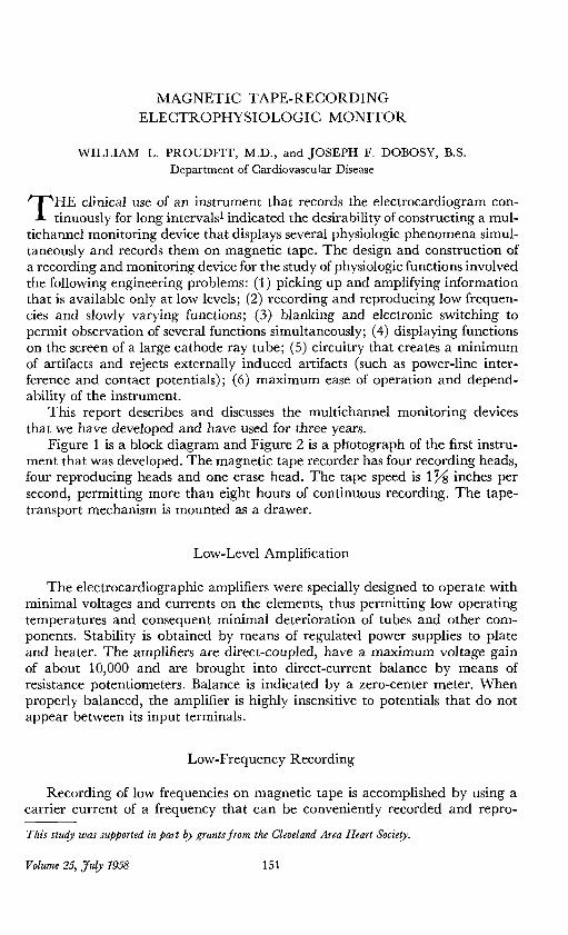
Figure 1 is a block diagram and Figure 2 is a photograph of the first instru-ment that was developed. The magnetic tape recorder has four recording heads, four reproducing heads and one erase head. The tape speed is l j ^ inches per second, permitting more than eight hours of continuous recording. The tape-transport mechanism is mounted as a drawer.
Low-Level Amplification
The electrocardiographic amplifiers were specially designed to operate with minimal voltages and currents on the elements, thus permitting low operating temperatures and consequent minimal deterioration of tubes and other com-ponents. Stability is obtained by means of regulated power supplies to plate and heater. The amplifiers are direct-coupled, have a maximum voltage gain of about 10,000 and are brought into direct-current balance by means of resistance potentiometers. Balance is indicated by a zero-center meter. When properly balanced, the amplifier is highly insensitive to potentials that do not appear between its input terminals.
Low-Frequency Recording
Recording of low frequencies on magnetic tape is accomplished by using a carrier current of a frequency that can be conveniently recorded and repro-
This study was supported in part by grants from the Cleveland Area Heart Society.
Volume 25, July 1958 1 5 1

P R O U D F I T AND DOBOSY
duced in an ordinary manner. The carrier is amplitude modulated by the information that is to be recorded. The modulated carrier is picked up from the tape by the reproducing head and is amplified and demodulated to yield the originally recorded information.
Input no. I
Input no. 2
Input no .3
O.A. M. O.A. M.
D.A. M. D.A. M.
Microphone Aud i ophone
[E~1 [RC] [RC] [RC] |RC] [RP] [RF>
T o p e R e c o r d e r
Fig. i. Block d iagram of magnet ic tape-recording electrophysiologic monitor .
D. A.- Dif ferentiol A m p i i f < er U. G. - Ultrosonic Generator M.- Modulator R.A.- Reproduce Amplifier R . -Rec t i f i e r E . -E rase Head
E .S . - Electronic Switch R.C.- Record Head V. A.- Vertical Ampl i f ier R. P. - Reproduce Head
C.R.T.-Cathode Ray Tube H.S.G.-Horizontal Sweep Gen. S.A.-Sound Ampl i f ier H.A.-Hor izonta l Ampl i f ier
The modulating and demodulating systems are unusual in that the carrier current is a square wave of 600 cycles. The modulator is a partially balanced device that is free of distortion even at 100 per cent modulation. The modulator units are similar to the electronic switches used in the deflection system, except that the electronic switches operate at 1,000 and 2,000 cycles instead of the 600 cycles of the modulators. The square-wave carrier has the advantage of simplicity of generation and control, and ease of removal of the carrier from the information by means of a full-wave demodulator and a simple resistance-capacitance filter. In this method of demodulation, the carrier is largely re-moved by cancellation, and the extent of carrier cancellation depends only on the rise time of the square wave and the balance of the demodulator. The tops of the carrier waves contain all modulations in full detail, even though they have a much higher frequency than that of the carrier. When the negative half of the cycle is reversed by the full-wave demodulator, this negative half of the carrier cycle falls precisely into place between two adjacent positive halves, thus returning all information to its original form with the addition of a sharp switching pulse occurring at double the frequency of the carrier. This pulse is of such short duration that a small amount of filtering easily removes it.
1 5 2 Cleveland Clinic Quarterly
M A G N E T I C T A P E - R E C O R D I N G ELECTROPHYSIOLOGIC M O N I T O R

P R O U D F I T AND DOBOSY
T h e modulated carrier, as reproduced from the magnetic tapes, does not have the fast rise time of the original modulated square wave. However, the third and the fifth harmonics are retained approximately in their original magnitudes and phases. The system is capable of recording and reproducing information accurately at frequencies as high as half the frequency of the carrier, because of the phase and magnitude equalizations used in the reproduce ampli-fiers. A tape speed of inches per second is employed but, with faster tape speeds, higher orders of harmonics of the carrier are retained, and still higher frequencies of information can be reproduced from the tape, even at the same carrier frequency.
Amplitude modulation of the carrier, compared to frequency modulation or some other form of modulation in time, has the advantage of being insensitive to variations in tape speed. This characteristic is important, because it is difficult to maintain the constant tape speed at the slow rate of \]/s inches per second, selected to permit the long, unattended recording time required. Amplitude modulation has the disadvantage of being sensitive to irregularities in the surface of the tape. Therefore, the tape must have uniform magnetic coating and a smooth finish for satisfactory reproduction.
Stability Considerations
It was advisable to use as much direct coupling as possible to assure minimal ringing. When direct coupling is used throughout, there is an optimal situation for realization of instant recovery from any extreme voltage excursions brought about by switching, lead changes, and other operational manipulations, and all responses to control are instantaneous. Unfortunately, however, it seems im-possible to make dependable contact with the body without generating a contact potential. Any contact potential can readily be balanced out, but usually such a potential is not constant, and causes a slow variation in the position of the base line. Therefore, one coupling condenser is incorporated into each channel to restore the base line automatically and continuously. The use of only one condenser, or a minimum of coupling condensers, minimizes ringing, and much of the simplicity of direct-coupled circuits is retained.
Large Screen Cathode Ray Tube
In monitoring it is advantageous to use large-screen cathode ray tubes when multiple functions are to be displayed. The electronic switching of the beam of a single electron gun permits the use of magnetic deflection, which in turn makes it possible to use a standard television picture tube that has been pro-vided with the necessary long-persistence phosphor. The horizontal sweep speed is variable over a range of 1/100 second to 10 seconds. The high sweep speeds are used to resolve the high frequencies and fast rise times of the elec-tronic switches for test purposes, and the slower sweep speeds are used for displaying physiologic functions.
1 5 4 Cleveland Clinic Quarterly

M A G N E T I C T A P E - R E C O R D I N G ELECTROPHYSIOLOGIC M O N I T O R
Blanking and Electronic Switching
The difficulty of magnetically deflecting the electron beam at extremely high speeds makes it desirable to blank the electron beam during the electronic switching interval. This is accomplished by differentiating the output of the vertical amplifier, and using the resulting pulses to cut off the electron beam during the switching intervals. As a result of this blanking, the traces are sharper and clearer.
To produce the four independent traces on the screen of the cathode ray tube, the outputs of two identical electronic switches are connected to the two inputs of a third electronic switch unit that is identical with the first two except that it operates at a frequency approximately twice that of the other two switches. Under these conditions, four traces are formed on the cathode ray screen, each trace being made up of short dashes occurring at approximately one-millisecond intervals. Each of these traces responds only to the signal applied to one of the four corresponding inputs of the first two electronic switches; they may be positioned as desired by means of three positioning controls on the panel.
Operation
The instrument is operated almost as though it were four independent instruments. Only necessary controls are brought out to the front panel, and each control has evident effects that are easy to understand. The screen traces are controllable as to brightness, focus, sweep rate, and position of trace. The amplifiers have gain and balance controls; the balance, as mentioned previously, is indicated by a zero-center meter.
Portable Model
A smaller instrument was built to fill a need for a device that would take up less space and would be more readily portable. It is essentially a copy of the original instrument (Fig. 3). Its principal differences lie in the use of a much smaller two-channel tape-recording mechanism and a 5-inch electrostatically deflected cathode ray tube. The complete unit weighs about forty pounds. One channel is arranged to record and reproduce low-frequency functions such as the electrocardiogram, and the other is utilized for frequencies in the audible range up to about 2,500 cycles. This latter channel is used primarily for record-ing cardiac sounds and speech. During the recording process, the information being recorded on both channels may be simultaneously monitored on the screen of the cathode ray tube, and the sound channel may be monitored by stethophone as well. The front panel controls on the portable unit are similar to those on the large four-channel instrument. Amplifier balance, however, is indicated by the simultaneous ignition of two small neon lamps.
Volume 25, July 1958 1 5 5

P R O U D F I T AND DOBOSY
Fig. 3. Photograph of portable monitor.
Applications
With the aid of special transducers and the addition of relatively simple circuitry, it has been possible to display a variety of information on the large screen of the cathode ray tube and at the same time to record the information. Among these phenomena are the electrocardiogram, the vectorcardiogram, the
1 5 6 Cleveland Clinic Quarterly

M A G N E T I C T A P E - R E C O R D I N G ELECTROPHYSIOLOGIC M O N I T O R
stethogram of cardiac sounds, the electroencephalogram, the ballistocardiogram, the myogram, and arterial pressure curves. Traces may be recorded by photo-graphing the face of the cathode ray tube or by feeding the information into a suitable string or D'Arsonval galvanometer. The recorded information can be reproduced any number of times and observed in the same manner as it was while it was being recorded. The ability to visualize the stethogram and electro-cardiogram reproduced simultaneously, facilitates the teaching of auscultation of the heart, because it enables the student to secure proper timing simply. Small loops of magnetic tape may be used for studying cardiac sounds.
Summary
Multichannel magnetic tape-recording instruments have been developed for monitoring physiologic functions. Problems encountered in the development of this type of equipment are outlined and solutions are presented. Electrocardio-grams, vectorcardiograms, electroencephalograms, stethograms, ballistocardio-grams, arterial-pulse curves and electromyograms have been recorded.
Reference
1, Proudfit, W. L., and Dobosy, J . F. : Magnetic tape recording electrocardiograph. Circula-tion 8: 735-737, 1953.
Volume 25, July 1958 1 5 7