Embed Size (px)
Citation preview
March · Vol. 84 · DP17644
320132013
www.steel-research.de
www.steel-research.de
© 2013 Wiley-VCH Verlag GmbH & Co. KGaA, Weinheim steel research int. 84 (2013) No. 3 203
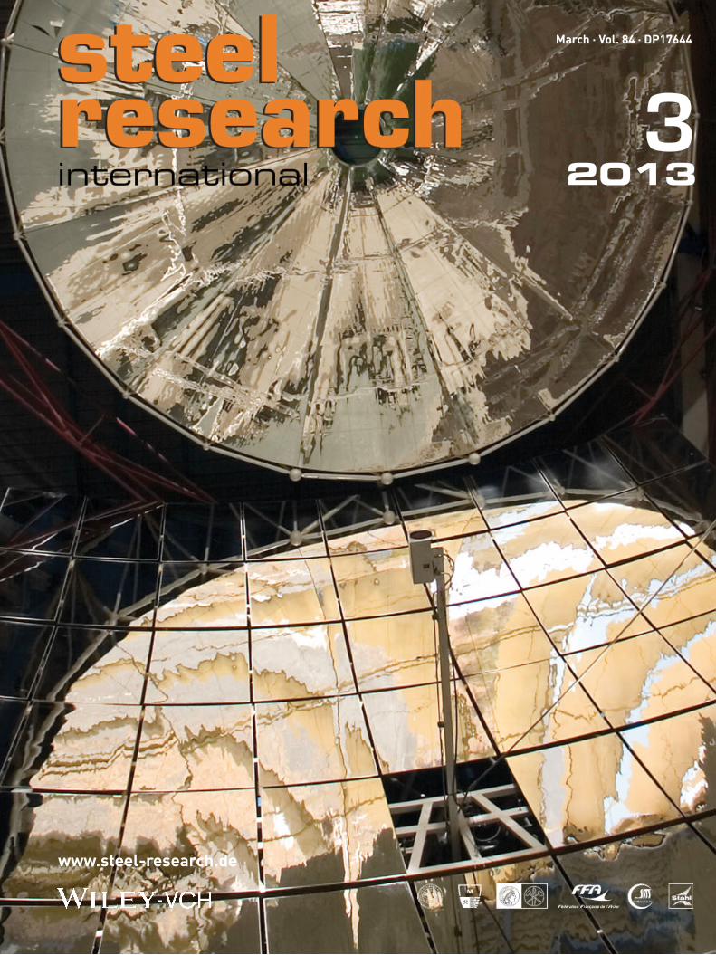
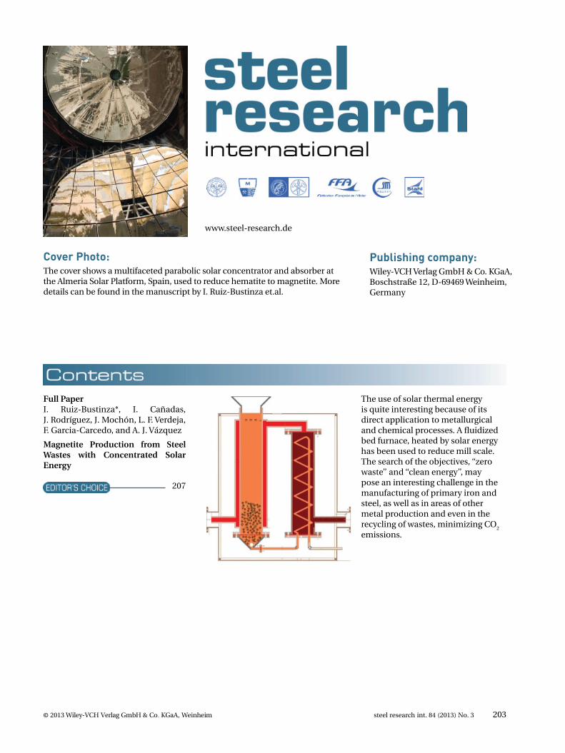
Cover Photo:The cover shows a multifaceted parabolic solar concentrator and absorber at the Almeria Solar Platform, Spain, used to reduce hematite to magnetite. More details can be found in the manuscript by I. Ruiz-Bustinza et.al.
Publishing company:Wiley-VCH Verlag GmbH & Co. KGaA,Boschstraße 12, D-69469 Weinheim,Germany
The use of solar thermal energy is quite interesting because of its direct application to metallurgical and chemical processes. A fl uidized bed furnace, heated by solar energy has been used to reduce mill scale. The search of the objectives, ‘‘zero waste’’ and ‘‘clean energy’’, may pose an interesting challenge in the manufacturing of primary iron and steel, as well as in areas of other metal production and even in the recycling of wastes, minimizing CO
2
emissions.
Full PaperI. Ruiz-Bustinza*, I. Cañadas, J. Rodríguez, J. Mochón, L. F. Verdeja, F. Garcia-Carcedo, and A. J. Vázquez
Magnetite Production from Steel Wastes with Concentrated Solar Energy
207
www.steel-research.de
204 steel research int. 84 (2013) No. 3 © 2013 Wiley-VCH Verlag GmbH & Co. KGaA, Weinheim
CFD modeling of steel fl ow and temperature fi elds are described during 5-strand long product tundish drainage at ORI Martin Steelworks. The vortices formation was shown, at fi rst from the strands close to corners. The bath height was found to avoid slag entrapment through vortices. Once applied into operating practice, no rejection or claims for cleanliness were achieved. The benefi cial effect of both good insulation and regular drainage rate to prevent steel freezing was found and confi rmed by a ORI campaign at tundish start operations including about 700 heats.
V. Battaglia, M. De Santis*, V. Volponi, and M. Zanforlin
Steel Thermo-Fluid-Dynamics at Tundish Drainage and Quality Features
237
T. S. Srivatsan*, K. Manigandan, A. M. Freborg, and T. Quick
Investigating and Understanding the Cyclic Fatigue, Deformation, and Fracture Behavior of a Novel High Strength Alloy Steel: Infl uence of Orientation
218
Infl uence of orientation on high cycle fatigue properties and fi nal fracture behavior of alloy steel Pyrowear 53 is the focus. Test specimens prepared from both the longitudinal and transverse orientations were deformed in cyclic fatigue over a range of maximum stress, under fully-reversed loading, and number of cycles-to-failure recorded. The fracture surfaces were examined to establish the macroscopic mode and characterize intrinsic features on the surface.
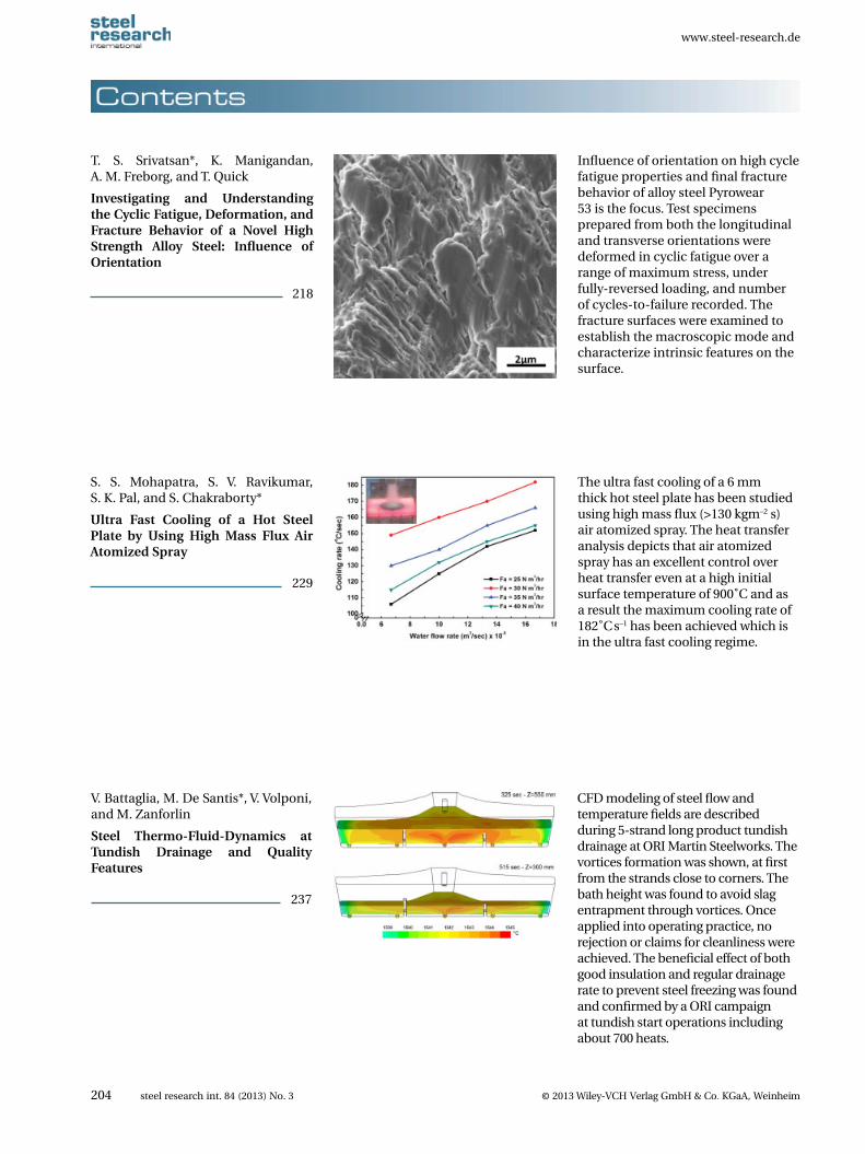
The ultra fast cooling of a 6 mm thick hot steel plate has been studied using high mass fl ux (>130 kgm–2 s) air atomized spray. The heat transfer analysis depicts that air atomized spray has an excellent control over heat transfer even at a high initial surface temperature of 900˚C and as a result the maximum cooling rate of 182˚C s–1 has been achieved which is in the ultra fast cooling regime.
S. S. Mohapatra, S. V. Ravikumar, S. K. Pal, and S. Chakraborty*
Ultra Fast Cooling of a Hot Steel Plate by Using High Mass Flux Air Atomized Spray
229
www.steel-research.de
© 2013 Wiley-VCH Verlag GmbH & Co. KGaA, Weinheim steel research int. 84 (2013) No. 3 205
Mean fl ow stresses are calculated from experimental fl ow curves determined on four steels of increasing C content. These are plotted against inverse temperature so as to defi ne the stress drop or upper critical temperature applicable to rolling. These temperatures are shown to be well above the equilibrium transformation temperatures, an observation that is attributed to the occurrence of dynamic transformation.
J. J. Jonas*, C. Ghosh, and V. V. Basabe
Effect of Dynamic Transformation on the Mean Flow Stress
253
The information provided in this paper can be applied in steel plant to measure the mold top surface velocity and meniscus fl uctuation with time variation. This work can be used to investigate the effect of EMBr and others casting condition on mold surface fl ow pattern and furthermore improving the casting defect. Also the method in this paper provides a way to validate the accuracy of computational model. This paper is free of charge.
C. Ji*, J. Li, H. Tang, and S. Yang
Effect of EMBr on Flow in Slab Con-tinuous Casting Mold and Evaluation Using Nail Dipping Measurement
259
An experimental technique developed for monitoring the work roll surface temperature by sensors embedded in the work roll is presented. Continuous hot rolling pilot line trials were performed for different process conditions. These thermal measurements give very detailed information about the temperature fi eld in the roll. The heat fl ux and heat transfer coeffi cient distribution along the roll circumference were obtained.
M. Raudensky*, J. Horsky, J. Ondrouskova, and B. Vervaet
Measurement of Thermal Load on Working Rolls during Hot Rolling
269
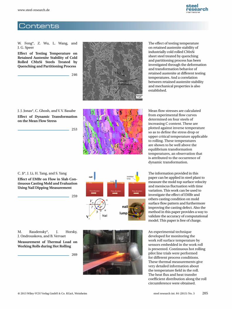
The effect of testing temperature on retained austenite stability of industrially cold rolled CMnSi sheet steel treated by quenching and partitioning process has been investigated through the deformation and transformation behavior of retained austenite at different testing temperatures. And a correlation between retained austenite stability and mechanical properties is also established.
W. Feng*, Z. Wu, L. Wang, and J. G. Speer
Effect of Testing Temperature on Retained Austenite Stability of Cold Rolled CMnSi Steels Treated by Quenching and Partitioning Process
246
www.steel-research.de
206 steel research int. 84 (2013) No. 3 © 2013 Wiley-VCH Verlag GmbH & Co. KGaA, Weinheim
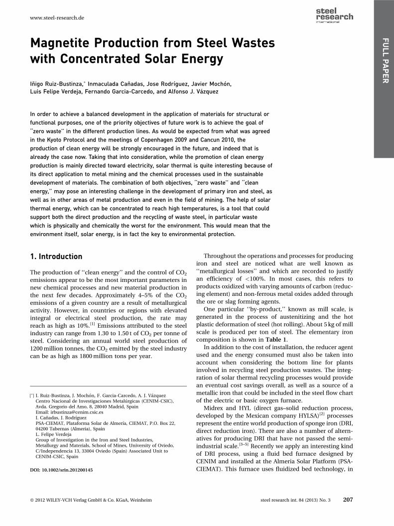
We propose in this publication the introduction of new, additional defi nition describing the multiple orifi ce ceramic fi lters used in research works on the liquid steel fi ltrations, calling this the fi lter slenderness ratio. Using this coeffi cient we obtain the possibility to compare the fi ltration effectiveness of different types of ceramic fi lters, not only for fi lters with cylindrical fi ltrating orifi ces, but also for other types, e.g., with orifi ces of rectangular section.
K. Janiszewski*
The Slenderness Ratio of the Filter Used in the Process of Liquid Steel Filtration as the Additional Param-eter of the Filter Form
288
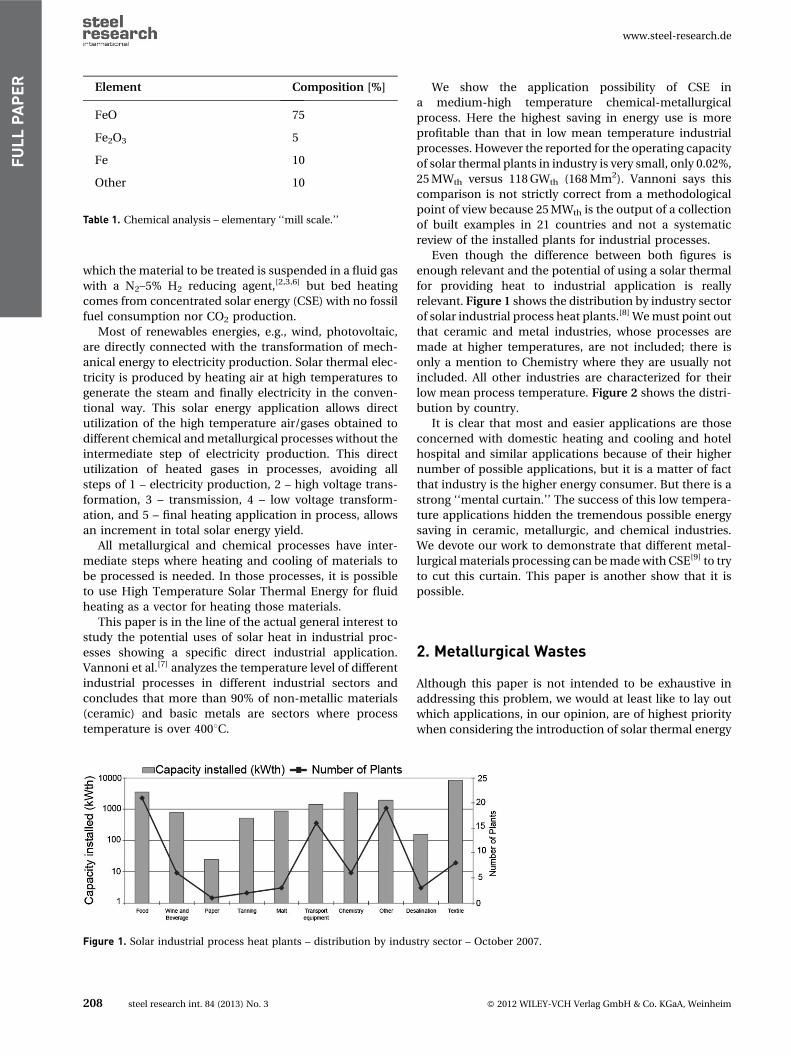
Strain induced martensitic transformation of retained austenite has been studied in Al-containing TRIP steel samples with similar retained austenite characteristics. It was found a difference of retained austenite stability by tensile straining along RD and TD. This behavior has been explained by the texture component of ferrite causes anisotropy of crystal plasticity so that more transformation of retained austenite is measured along RD rather than TD.
E. Emadoddin*, A. Akbarzadeh, R. Petrov, and L. Zhao
Anisotropy of Retained Austenite Stability during Transformation to Martensite in a TRIP-Assisted Steel
297
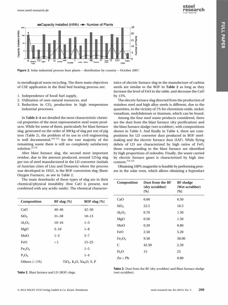
This paper described jet characteristics of conventional and various swirl-type oxygen lances by water model experiment and numerical simulation. The swirl-type oxygen lance was experimented in 150 t vanadium extraction converter. The research shows that the swirl-type lance can strengthen stirring ability and guarantee the normal converter vanadium extraction process. It is helpful to improve vanadium extraction effi ciency.
M. Lv*, R. Zhu, H. Wang, and R. G. Bai
Simulation and Application of Swirl-Type Oxygen Lance in Vanadium Ex-traction Converter
304
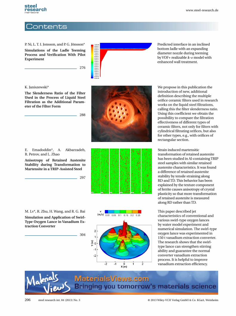
Predicted interface in an inclined bottom ladle with an expanding diameter nozzle during teeming by VOF+ realizable k–� model with enhanced wall treatment.
P. Ni, L. T. I. Jonsson, and P. G. Jönsson*
Simulations of the Ladle Teeming Process and Verifi cation With Pilot Experiment
276
Magnetite Production from Steel Wasteswith Concentrated Solar Energy
Inigo Ruiz-Bustinza,� Inmaculada Canadas, Jose Rodrıguez, Javier Mochon,Luis Felipe Verdeja, Fernando Garcia-Carcedo, and Alfonso J. Vazquez
In order to achieve a balanced development in the application of materials for structural or
functional purposes, one of the priority objectives of future work is to achieve the goal of
‘‘zero waste’’ in the different production lines. As would be expected from what was agreed
in the Kyoto Protocol and the meetings of Copenhagen 2009 and Cancun 2010, the
production of clean energy will be strongly encouraged in the future, and indeed that is
already the case now. Taking that into consideration, while the promotion of clean energy
production is mainly directed toward electricity, solar thermal is quite interesting because of
its direct application to metal mining and the chemical processes used in the sustainable
development of materials. The combination of both objectives, ‘‘zero waste’’ and ‘‘clean
energy,’’ may pose an interesting challenge in the development of primary iron and steel, as
well as in other areas of metal production and even in the field of mining. The help of solar
thermal energy, which can be concentrated to reach high temperatures, is a tool that could
support both the direct production and the recycling of waste steel, in particular waste
which is physically and chemically the worst for the environment. This would mean that the
environment itself, solar energy, is in fact the key to environmental protection.
1. Introduction
The production of ‘‘clean energy’’ and the control of CO2
emissions appear to be the most important parameters in
new chemical processes and new material production in
the next few decades. Approximately 4–5% of the CO2
emissions of a given country are a result of metallurgical
activity. However, in countries or regions with elevated
integral or electrical steel production, the rate may
reach as high as 10%.[1] Emissions attributed to the steel
industry can range from 1.30 to 1.50 t of CO2 per tonne of
steel. Considering an annual world steel production of
1200 million tonnes, the CO2 emitted by the steel industry
can be as high as 1800 million tons per year.
Throughout the operations and processes for producing
iron and steel are noticed what are well known as
‘‘metallurgical losses’’ and which are recorded to justify
an efficiency of <100%. In most cases, this refers to
products oxidized with varying amounts of carbon (reduc-
ing element) and non-ferrous metal oxides added through
the ore or slag forming agents.
One particular ‘‘by-product,’’ known as mill scale, is
generated in the process of austenitizing and the hot
plastic deformation of steel (hot rolling). About 5 kg of mill
scale is produced per ton of steel. The elementary iron
composition is shown in Table 1.
In addition to the cost of installation, the reducer agent
used and the energy consumed must also be taken into
account when considering the bottom line for plants
involved in recycling steel production wastes. The integ-
ration of solar thermal recycling processes would provide
an eventual cost savings overall, as well as a source of a
metallic iron that could be included in the steel flow chart
of the electric or basic oxygen furnace.
Midrex and HYL (direct gas–solid reduction process,
developed by the Mexican company HYLSA)[2] processes
represent the entire world production of sponge iron (DRI,
direct reduction iron). There are also a number of altern-
atives for producing DRI that have not passed the semi-
industrial scale.[3–5] Recently we apply an interesting kind
of DRI process, using a fluid bed furnace designed by
CENIM and installed at the Almeria Solar Platform (PSA-
CIEMAT). This furnace uses fluidized bed technology, in
[�] I. Ruiz-Bustinza, J. Mochon, F. Garcia-Carcedo, A. J. VazquezCentro Nacional de Investigaciones Metalurgicas (CENIM-CSIC),Avda. Gregorio del Amo, 8, 28040 Madrid, SpainEmail: [email protected]. Canadas, J. RodrıguezPSA-CIEMAT, Plataforma Solar de Almerıa, CIEMAT, P.O. Box 22,04200 Tabernas (Almeria), SpainL. Felipe VerdejaGroup of Investigation in the Iron and Steel Industries,Metallurgy and Materials, School of Mines, University of Oviedo,C/Independencia 13, 33004 Oviedo (Spain) Associated Unit toCENIM-CSIC, Spain
DOI: 10.1002/srin.201200145
www.steel-research.de
� 2012 WILEY-VCH Verlag GmbH & Co. KGaA, Weinheim steel research int. 84 (2013) No. 3 207
FULLPAPER
which the material to be treated is suspended in a fluid gas
with a N2–5% H2 reducing agent,[2,3,6] but bed heating
comes from concentrated solar energy (CSE) with no fossil
fuel consumption nor CO2 production.
Most of renewables energies, e.g., wind, photovoltaic,
are directly connected with the transformation of mech-
anical energy to electricity production. Solar thermal elec-
tricity is produced by heating air at high temperatures to
generate the steam and finally electricity in the conven-
tional way. This solar energy application allows direct
utilization of the high temperature air/gases obtained to
different chemical and metallurgical processes without the
intermediate step of electricity production. This direct
utilization of heated gases in processes, avoiding all
steps of 1 – electricity production, 2 – high voltage trans-
formation, 3 – transmission, 4 – low voltage transform-
ation, and 5 – final heating application in process, allows
an increment in total solar energy yield.
All metallurgical and chemical processes have inter-
mediate steps where heating and cooling of materials to
be processed is needed. In those processes, it is possible
to use High Temperature Solar Thermal Energy for fluid
heating as a vector for heating those materials.
This paper is in the line of the actual general interest to
study the potential uses of solar heat in industrial proc-
esses showing a specific direct industrial application.
Vannoni et al.[7] analyzes the temperature level of different
industrial processes in different industrial sectors and
concludes that more than 90% of non-metallic materials
(ceramic) and basic metals are sectors where process
temperature is over 4008C.
We show the application possibility of CSE in
a medium-high temperature chemical-metallurgical
process. Here the highest saving in energy use is more
profitable than that in low mean temperature industrial
processes. However the reported for the operating capacity
of solar thermal plants in industry is very small, only 0.02%,
25 MWth versus 118 GWth (168 Mm2). Vannoni says this
comparison is not strictly correct from a methodological
point of view because 25 MWth is the output of a collection
of built examples in 21 countries and not a systematic
review of the installed plants for industrial processes.
Even though the difference between both figures is
enough relevant and the potential of using a solar thermal
for providing heat to industrial application is really
relevant. Figure 1 shows the distribution by industry sector
of solar industrial process heat plants.[8] We must point out
that ceramic and metal industries, whose processes are
made at higher temperatures, are not included; there is
only a mention to Chemistry where they are usually not
included. All other industries are characterized for their
low mean process temperature. Figure 2 shows the distri-
bution by country.
It is clear that most and easier applications are those
concerned with domestic heating and cooling and hotel
hospital and similar applications because of their higher
number of possible applications, but it is a matter of fact
that industry is the higher energy consumer. But there is a
strong ‘‘mental curtain.’’ The success of this low tempera-
ture applications hidden the tremendous possible energy
saving in ceramic, metallurgic, and chemical industries.
We devote our work to demonstrate that different metal-
lurgical materials processing can be made with CSE[9] to try
to cut this curtain. This paper is another show that it is
possible.
2. Metallurgical Wastes
Although this paper is not intended to be exhaustive in
addressing this problem, we would at least like to lay out
which applications, in our opinion, are of highest priority
when considering the introduction of solar thermal energy
Element Composition [%]
FeO 75
Fe2O3 5
Fe 10
Other 10
Table 1. Chemical analysis – elementary ‘‘mill scale.’’
Figure 1. Solar industrial process heat plants – distribution by industry sector – October 2007.
www.steel-research.de
208 steel research int. 84 (2013) No. 3 � 2012 WILEY-VCH Verlag GmbH & Co. KGaA, Weinheim
FULLPAPER
to metallurgical waste recycling. The three main objectives
of CSE application in the fluid bed heating process are:
1. Independence of fossil fuel supply,
2. Utilization of own natural resources, and
3. Reduction in CO2 production in high temperature
industrial processes.
In Table 2–4 are detailed the most characteristic chemi-
cal properties of the most representative steel waste prod-
ucts. While for some of them, particularly for blast furnace
slag, generated on the order of 300 kg of slag per ton of pig
iron (Table 2), the problem of its use in civil engineering
is well documented,[10–12] for the vast majority of the
remaining waste there is still no completely satisfactory
solution.[2,13]
After blast furnace slag, the second most important
residue, due to the amount produced, around 125 kg slag
per ton of steel manufactured in the LD converter (initials
of Austrian cities of Linz and Donawitz where the process
was developed in 1952), is the BOF conversion slag (Basic
Oxygen Furnace), as see in Table 2.
The main drawbacks of these types of slag are in their
chemical/physical instability (free CaO is present, not
combined with any acidic oxide). The chemical character-
istics of electric furnace slag in the manufacture of carbon
steels are similar to the BOF in Table 2 as long as they
increase the level of FeO in the table, and decrease the CaO
by 15%.
The electric furnace slag directed from the production of
stainless steel and high alloy steels is different, due to the
quantities, in the vicinity of 1% for chromium oxide, nickel,
vanadium, molybdenum or titanium, which can be found.
Among the four steel waste products considered, there
are the dust from the blast furnace (dry purification) and
the blast furnace sludge (wet scrubber), with compositions
shown in Table 3. And finally in Table 4, there are com-
positions for LD converter dust produced in BOF steel-
making and the electric furnace dust (EAF). While flying
debris of LD are characterized by high ratios of FeO,
those corresponding to the blast furnace are identified
by high proportions of redoubts. Finally, the waste carried
by electric furnace gases is characterized by high zinc
content.[14,15]
Obtaining 100% magnetite is feasible by performing proc-
ess in the solar oven, which allows obtaining a byproduct
Figure 2. Solar industrial process heat plants – distribution by country – October 2007.
Composition BF slag [%] BOF slag [%]
CaO 40–46 42–50
SiO2 31–38 10–13
Al2O3 10–16 1–3
MgO 5–10 1–8
MnO 1–3 3–7
FeO <1 15–25
Fe2O3 1–5
P2O5 1–4
Others (<1%) TiO2, K2O, Na2O, S, P
Table 2. Blast furnace and LD (BOF) slags.
Composition Dust from the BF
(dry scrubber)
[%]
BF sludge
(Wet scrubber)
[%]
CaO 6.60 6.50
SiO2 22.5 18.5
Al2O3 0.70 1.50
MgO 0.50 1.50
MnO 0.20 0.80
FeO 2.50 5.20
Fe2O3 9.50 38.00
C 42.50 2.20
H2O 15 25
ZnþPb 0.80
Table 3. Dust from the BF (dry scrubber) and Blast furnace sludge(wet scrubber).
www.steel-research.de
� 2012 WILEY-VCH Verlag GmbH & Co. KGaA, Weinheim steel research int. 84 (2013) No. 3 209
FULLPAPER
with special magnetic properties susceptible of concentra-
tionby traditional methods, commonly used to produce con-
centrates from raw materials by magnetic separation.
Solar energy would be a step to recycle products, with
high concentrations of Fe3O4 and free from harmful con-
taminants, which can be added to the steelmaking process
to make a high quality steel.
Specifically, using the solar furnace plant of Almerıa
(Spain), the process has been tested with the mill scale,
one of the less complex metallurgical wastes from the
chemical point of view (Table 1). We have tried to dem-
onstrate the possibility of reach an experimental certainty
about the following issues:
(a) The possibility of using the solar furnace for the partial
reduction of Fe2O3 to Fe3O4.
(b) Obtaining a of high purity Fe3O4 product, commonly
used as feedstock for aluminothermy welding of
railway rails.
The fact that achieve the above objectives, treating mill
scale, has led the authors to extrapolate these results to
other applications of solar energy in the other residues
mentioned above; dust and sludge from the blast furnace,
the LD converter dust and the EAF, and also to other raw
materials such as sintered product that currently feeds
most of the blast furnaces in integrated steel production
of carbon steels.
From the experimental data obtained from the treat-
ment of mill scale, the following applications of solar
energy could be considered:
(a) Convert the iron ore fines used in the sintering process,
mostly Fe2O3, to magnetite (Fe3O4).
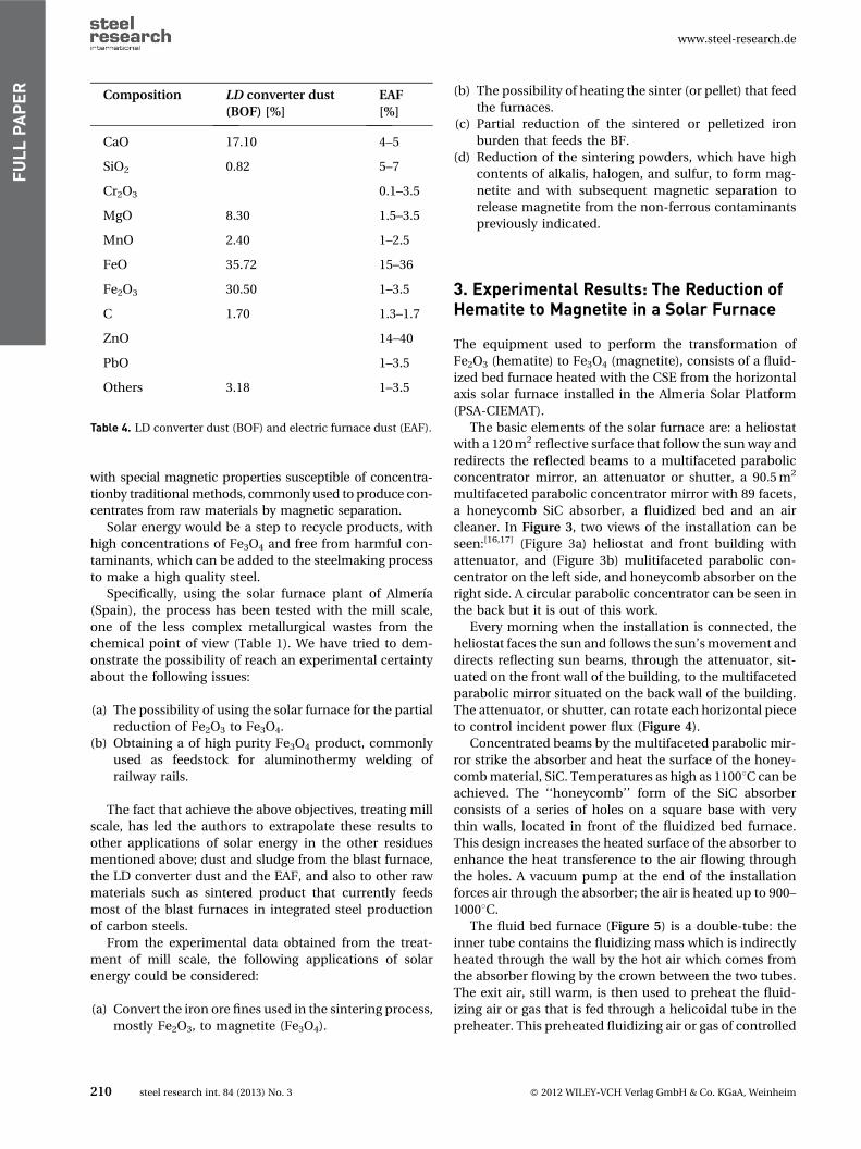
(b) The possibility of heating the sinter (or pellet) that feed
the furnaces.
(c) Partial reduction of the sintered or pelletized iron
burden that feeds the BF.
(d) Reduction of the sintering powders, which have high
contents of alkalis, halogen, and sulfur, to form mag-
netite and with subsequent magnetic separation to
release magnetite from the non-ferrous contaminants
previously indicated.
3. Experimental Results: The Reduction ofHematite to Magnetite in a Solar Furnace
The equipment used to perform the transformation of
Fe2O3 (hematite) to Fe3O4 (magnetite), consists of a fluid-
ized bed furnace heated with the CSE from the horizontal
axis solar furnace installed in the Almeria Solar Platform
(PSA-CIEMAT).
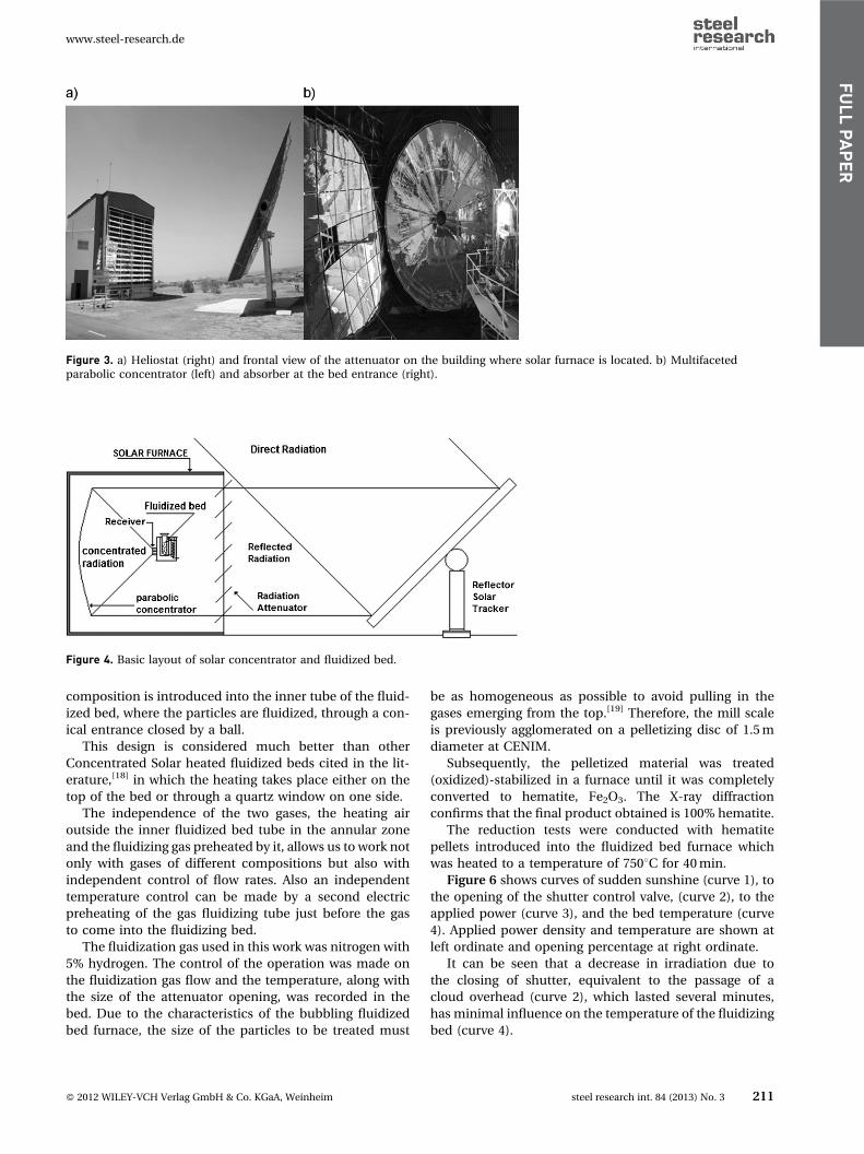
The basic elements of the solar furnace are: a heliostat
with a 120 m2 reflective surface that follow the sun way and
redirects the reflected beams to a multifaceted parabolic
concentrator mirror, an attenuator or shutter, a 90.5 m2
multifaceted parabolic concentrator mirror with 89 facets,
a honeycomb SiC absorber, a fluidized bed and an air
cleaner. In Figure 3, two views of the installation can be
seen:[16,17] (Figure 3a) heliostat and front building with
attenuator, and (Figure 3b) mulitifaceted parabolic con-
centrator on the left side, and honeycomb absorber on the
right side. A circular parabolic concentrator can be seen in
the back but it is out of this work.
Every morning when the installation is connected, the
heliostat faces the sun and follows the sun’s movement and
directs reflecting sun beams, through the attenuator, sit-
uated on the front wall of the building, to the multifaceted
parabolic mirror situated on the back wall of the building.
The attenuator, or shutter, can rotate each horizontal piece
to control incident power flux (Figure 4).
Concentrated beams by the multifaceted parabolic mir-
ror strike the absorber and heat the surface of the honey-
comb material, SiC. Temperatures as high as 11008C can be
achieved. The ‘‘honeycomb’’ form of the SiC absorber
consists of a series of holes on a square base with very
thin walls, located in front of the fluidized bed furnace.
This design increases the heated surface of the absorber to
enhance the heat transference to the air flowing through
the holes. A vacuum pump at the end of the installation
forces air through the absorber; the air is heated up to 900–
10008C.
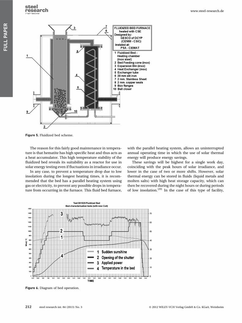
The fluid bed furnace (Figure 5) is a double-tube: the
inner tube contains the fluidizing mass which is indirectly
heated through the wall by the hot air which comes from
the absorber flowing by the crown between the two tubes.
The exit air, still warm, is then used to preheat the fluid-
izing air or gas that is fed through a helicoidal tube in the
preheater. This preheated fluidizing air or gas of controlled
Composition LD converter dust
(BOF) [%]
EAF
[%]
CaO 17.10 4–5
SiO2 0.82 5–7
Cr2O3 0.1–3.5
MgO 8.30 1.5–3.5
MnO 2.40 1–2.5
FeO 35.72 15–36
Fe2O3 30.50 1–3.5
C 1.70 1.3–1.7
ZnO 14–40
PbO 1–3.5
Others 3.18 1–3.5
Table 4. LD converter dust (BOF) and electric furnace dust (EAF).
www.steel-research.de
210 steel research int. 84 (2013) No. 3 � 2012 WILEY-VCH Verlag GmbH & Co. KGaA, Weinheim
FULLPAPER
composition is introduced into the inner tube of the fluid-
ized bed, where the particles are fluidized, through a con-
ical entrance closed by a ball.
This design is considered much better than other
Concentrated Solar heated fluidized beds cited in the lit-
erature,[18] in which the heating takes place either on the
top of the bed or through a quartz window on one side.
The independence of the two gases, the heating air
outside the inner fluidized bed tube in the annular zone
and the fluidizing gas preheated by it, allows us to work not
only with gases of different compositions but also with
independent control of flow rates. Also an independent
temperature control can be made by a second electric
preheating of the gas fluidizing tube just before the gas
to come into the fluidizing bed.
The fluidization gas used in this work was nitrogen with
5% hydrogen. The control of the operation was made on
the fluidization gas flow and the temperature, along with
the size of the attenuator opening, was recorded in the
bed. Due to the characteristics of the bubbling fluidized
bed furnace, the size of the particles to be treated must
be as homogeneous as possible to avoid pulling in the
gases emerging from the top.[19] Therefore, the mill scale
is previously agglomerated on a pelletizing disc of 1.5 m
diameter at CENIM.
Subsequently, the pelletized material was treated
(oxidized)-stabilized in a furnace until it was completely
converted to hematite, Fe2O3. The X-ray diffraction
confirms that the final product obtained is 100% hematite.
The reduction tests were conducted with hematite
pellets introduced into the fluidized bed furnace which
was heated to a temperature of 7508C for 40 min.
Figure 6 shows curves of sudden sunshine (curve 1), to
the opening of the shutter control valve, (curve 2), to the
applied power (curve 3), and the bed temperature (curve
4). Applied power density and temperature are shown at
left ordinate and opening percentage at right ordinate.
It can be seen that a decrease in irradiation due to
the closing of shutter, equivalent to the passage of a
cloud overhead (curve 2), which lasted several minutes,
has minimal influence on the temperature of the fluidizing
bed (curve 4).
Figure 3. a) Heliostat (right) and frontal view of the attenuator on the building where solar furnace is located. b) Multifacetedparabolic concentrator (left) and absorber at the bed entrance (right).
Figure 4. Basic layout of solar concentrator and fluidized bed.
www.steel-research.de
� 2012 WILEY-VCH Verlag GmbH & Co. KGaA, Weinheim steel research int. 84 (2013) No. 3 211
FULLPAPER
The reason for this fairly good maintenance in tempera-
ture is that hematite has high specific heat and thus acts as
a heat accumulator. This high temperature stability of the
fluidized bed reveals its suitability as a reactor for use in
solar energy testing even if fluctuations in irradiance occur.
In any case, to prevent a temperature drop due to low
insolation during the longest heating times, it is recom-
mended that the bed has a parallel heating system using
gas or electricity, to prevent any possible drops in tempera-
ture from occurring in the furnace. This fluid bed furnace,
with the parallel heating system, allows an uninterrupted
annual operating time in which the use of solar thermal
energy will produce energy savings.
These savings will be highest for a single work day,
coinciding with the peak hours of solar irradiance, and
lower in the case of two or more shifts. However, solar
thermal energy can be stored in fluids (liquid metals and
molten salts) with high heat storage capacity, which can
then be recovered during the night hours or during periods
of low insolation.[20] In the case of this type of facility,
Figure 5. Fluidized bed scheme.
Figure 6. Diagram of bed operation.
www.steel-research.de
212 steel research int. 84 (2013) No. 3 � 2012 WILEY-VCH Verlag GmbH & Co. KGaA, Weinheim
FULLPAPER
which requires a large investment, it is preferable that all
energy consumed is of solar origin.
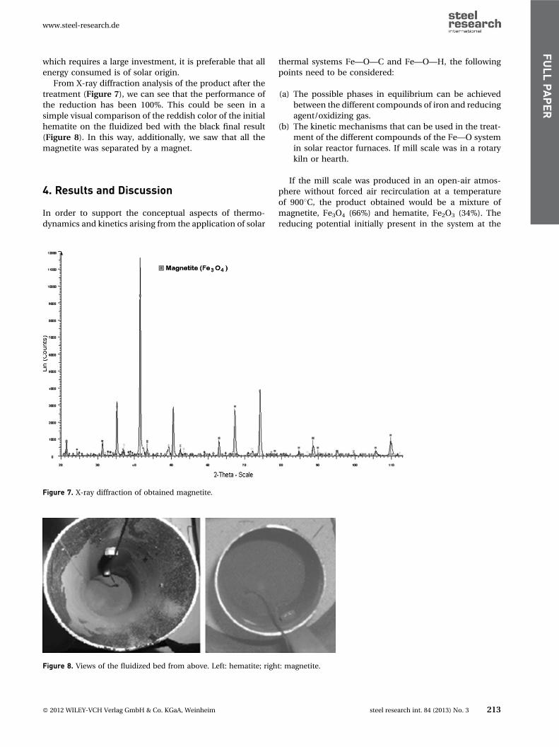
From X-ray diffraction analysis of the product after the
treatment (Figure 7), we can see that the performance of
the reduction has been 100%. This could be seen in a
simple visual comparison of the reddish color of the initial
hematite on the fluidized bed with the black final result
(Figure 8). In this way, additionally, we saw that all the
magnetite was separated by a magnet.
4. Results and Discussion
In order to support the conceptual aspects of thermo-
dynamics and kinetics arising from the application of solar
thermal systems Fe—O—C and Fe—O—H, the following
points need to be considered:
(a) The possible phases in equilibrium can be achieved
between the different compounds of iron and reducing
agent/oxidizing gas.
(b) The kinetic mechanisms that can be used in the treat-
ment of the different compounds of the Fe—O system
in solar reactor furnaces. If mill scale was in a rotary
kiln or hearth.
If the mill scale was produced in an open-air atmos-
phere without forced air recirculation at a temperature
of 9008C, the product obtained would be a mixture of
magnetite, Fe3O4 (66%) and hematite, Fe2O3 (34%). The
reducing potential initially present in the system at the
Figure 7. X-ray diffraction of obtained magnetite.
Figure 8. Views of the fluidized bed from above. Left: hematite; right: magnetite.
www.steel-research.de
� 2012 WILEY-VCH Verlag GmbH & Co. KGaA, Weinheim steel research int. 84 (2013) No. 3 213
FULLPAPER
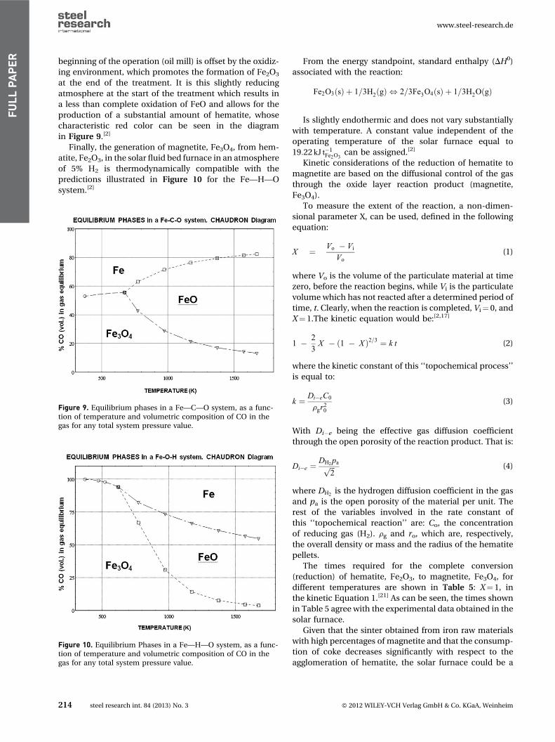
beginning of the operation (oil mill) is offset by the oxidiz-
ing environment, which promotes the formation of Fe2O3
at the end of the treatment. It is this slightly reducing
atmosphere at the start of the treatment which results in
a less than complete oxidation of FeO and allows for the
production of a substantial amount of hematite, whose
characteristic red color can be seen in the diagram
in Figure 9.[2]
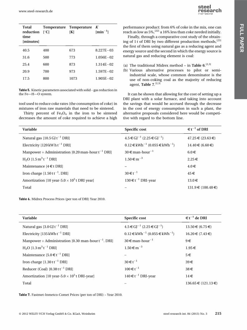
Finally, the generation of magnetite, Fe3O4, from hem-
atite, Fe2O3, in the solar fluid bed furnace in an atmosphere
of 5% H2 is thermodynamically compatible with the
predictions illustrated in Figure 10 for the Fe—H—O
system.[2]
From the energy standpoint, standard enthalpy (DH0)
associated with the reaction:
Fe2O3ðsÞ þ 1=3H2ðgÞ , 2=3Fe3O4ðsÞ þ 1=3H2OðgÞ
Is slightly endothermic and does not vary substantially
with temperature. A constant value independent of the
operating temperature of the solar furnace equal to
19:22 kJ t�1Fe2O3
can be assigned.[2]
Kinetic considerations of the reduction of hematite to
magnetite are based on the diffusional control of the gas
through the oxide layer reaction product (magnetite,
Fe3O4).
To measure the extent of the reaction, a non-dimen-
sional parameter X, can be used, defined in the following
equation:
X ¼ Vo � Vi
Vo(1)
where Vo is the volume of the particulate material at time
zero, before the reaction begins, while Vi is the particulate
volume which has not reacted after a determined period of
time, t. Clearly, when the reaction is completed, Vi¼ 0, and
X¼ 1.The kinetic equation would be:[2,17]
1 � 2
3X � ð1 � X Þ2=3 ¼ k t (2)
where the kinetic constant of this ‘‘topochemical process’’
is equal to:
k ¼ Di�eC0
rgr20
(3)
With Di�e being the effective gas diffusion coefficient
through the open porosity of the reaction product. That is:
Di�e ¼DH2pa
ffiffiffi
2p (4)
where DH2is the hydrogen diffusion coefficient in the gas
and pa is the open porosity of the material per unit. The
rest of the variables involved in the rate constant of
this ‘‘topochemical reaction’’ are: Co, the concentration
of reducing gas (H2). rg and ro, which are, respectively,
the overall density or mass and the radius of the hematite
pellets.
The times required for the complete conversion
(reduction) of hematite, Fe2O3, to magnetite, Fe3O4, for
different temperatures are shown in Table 5: X¼ 1, in
the kinetic Equation 1.[21] As can be seen, the times shown
in Table 5 agree with the experimental data obtained in the
solar furnace.
Given that the sinter obtained from iron raw materials
with high percentages of magnetite and that the consump-
tion of coke decreases significantly with respect to the
agglomeration of hematite, the solar furnace could be a
Figure 9. Equilibrium phases in a Fe—C—O system, as a func-tion of temperature and volumetric composition of CO in thegas for any total system pressure value.
Figure 10. Equilibrium Phases in a Fe—H—O system, as a func-tion of temperature and volumetric composition of CO in thegas for any total system pressure value.
www.steel-research.de
214 steel research int. 84 (2013) No. 3 � 2012 WILEY-VCH Verlag GmbH & Co. KGaA, Weinheim
FULLPAPER
tool used to reduce coke rates (the consumption of coke) in
mixtures of iron raw materials that need to be sintered.
Thirty percent of Fe3O4 in the iron to be sintered
decreases the amount of coke required to achieve a high
performance product: from 6% of coke in the mix, one can
reach as low as 5%,[22] a 16% less than coke needed initially.
Finally, through a comparative cost study of the obtain-
ing of 1 t of DRI by two different production methods,[23]
the first of them using natural gas as a reducing agent and
energy source and the second in which the energy source is
natural gas and reducing element is coal:
(a) The traditional Midrex method – in Table 6.[2,3]
(b) Various alternative processes to pilot or semi-
industrial scale, whose common denominator is the
use of non-coking coal as the majority of reducing
agent, Table 7.[2,3]
It can be shown that allowing for the cost of setting up a
DRI plant with a solar furnace, and taking into account
the savings that would be accrued through the decrease
in the cost of energy consumption in such a plant, the
alternative proposals considered here would be competi-
tive with regard to the bottom line.
Total
reduction
time
[minutes]
Temperature
[8C]Temperature
[K]
K
[min�1]
40.5 400 673 8.227E�03
31.6 500 773 1.056E�02
25.4 600 873 1.314E�02
20.9 700 973 1.597E�02
17.5 800 1073 1.905E�02
Table 5. Kinetic parameters associated with solid – gas reduction inthe Fe—H—O system.
Variable Specific cost s t�1 of DRI
Natural gas [10.5 GJ t�1 DRI] 4.5sGJ�1 (2.25sGJ�1) 47.25s (23.63s)
Electricity [120 kW h t�1 DRI] 0.12s kWh�1 (0.055s kWh�1) 14.40s (6.60s)
ManpowerþAdministration [0.20 man-hour t�1 DRI] 30sman-hour�1 6.0s
H2O [1.5 m3 t�1 DRI] 1.50sm�3 2.25s
Maintenance [4s t DRI] – 4.0s
Iron charge [1.50 t t�1. DRI] 30s t�1 45s
Amortization [10 year-5.0� 105 t DRI year] 130s t�1 DRI-year 13.0s
Total – 131.9s (100.48s)
Table 6. Midrex Process Prices (per ton of DRI) Year 2010.
Variable Specific cost s t�1 de DRI
Natural gas [3.0 GJ t�1 DRI] 4.5sGJ�1 (2.25sGJ�1) 13.50s (6.75s)
Electricity [135 kWh t�1 DRI] 0.12s kWh�1 (0.055s kWh�1) 16.20s (7.43s)
ManpowerþAdministration [0.30 man-hour t�1. DRI] 30sman-hour�1 9s
H2O [1.3 m3 t�1 DRI] 1.50sm�3 1.95s
Maintenance [5.0s t�1 DRI] – 5s
Iron charge [1.30 t t�1 DRI] 30s t�1 39s
Reducer (Coal) [0.38 t t�1 DRI] 100s t�1 38s
Amortization [10 year-5.0� 105 t DRI-year] 140s t�1 DRI-year 14s
Total – 136.65s (121.13s)
Table 7. Fastmet-Inmetco-Comet Prices (per ton of DRI) – Year 2010.
www.steel-research.de
� 2012 WILEY-VCH Verlag GmbH & Co. KGaA, Weinheim steel research int. 84 (2013) No. 3 215
FULLPAPER
Obviously, when treating ferrous-carbon waste in a solar
furnace, not only would there be a cost savings derived
from using less energy and requiring less iron ore in the
first place, but also those related to reducing consumption
(by recycling waste, which would save a lot of carbon).
In this case, the profit and cost savings that would result
from the installation of a solar furnace, despite the initial
investment associated with it, would be greater.
5. Conclusions
This paper shows how a fluidized bed heated by solar
energy reduces pelletized hematite to magnetite. The tem-
peratures reached in the bed are far superior to the mini-
mum necessary to achieve the reduction of hematite with
hydrogen (a mixture of 5% hydrogen in nitrogen).
We can conclude:
1. Concentrated solar energy (CSE) is a suitable way to
heat a fluidized bed at high temperatures. CSE heated
fluid bed is a reactor suitable to perform reduction of
mill scale and many other reactions using this kind of
reactor at reaction temperatures up to those obtained in
this work.
2. Intermittence of solar irradiance, simulated with a clos-
ing of shutter, don’t produce variations that affect the
heating process of the fluid bed thanks to the thermal
inertia of reactants inside the bed. Secondary electric
heating was not needed in this work to compensate
possible insufficient heating due to variations in sun
irradiance.
3. The industrial reduction of hematite to magnetite can
be performed with CSE. If we would like to work
24 h day�1 we need to introduce parallel heating systems
(electric or gas) or introduce existing fluid storage sys-
tems for high use of CSE.
4. The system of preheating fluidizing gas may be
improved upon using a helicoidal tube in a second
bed with sand, which would fluidize with hot air, instead
of the current design.
5. With the practice of double heating, energy conserva-
tion in addition to a reduction in CO2 emissions is
evident, on an annual basis, if a N2/H2 mixture is used
as a reducing agent. The estimated production of CO2,
now, in a reasonably sunny location, is on the order of
70/80% of energy consumption, which might be higher
if the processing temperature were lower.
6. The use of solar furnaces must be introduced to all kind
of processes chemical or metallurgical and, certainly, in
those of recycling when medium or high temperatures
are needed as it happens in the treatment of any steel
waste as noted in this project (including those con-
sidered ‘‘eco-toxic’’). Even in conventional processes
CSE can be used for preheating of combustion air with
independence of the temperature obtained according
the kind of concentrator equipment. In all of them
savings in energy costs and raw materials (ferrous
and reducers), may provide some leeway in assessing
the investment needed to install solar DRI-reduction
facilities, compared to the existing DRI plants in the
market.
7. It has been shown that it is possible to carry out the
reduction of hematite to magnetite in a solar furnace,
from a steel by-product like the mill scale. It could think
about apply this knowledge to other areas of the steel-
making process, as in the partial reduction of iron ores
used in the burden of sinter process.
Acknowledgments
This work was performed under the PSA–CENIM agree-
ment within the CIEMAT–PSA framework for joint use of
facilities. The authors wish to thank Mr. Javier Llorente for
his help during the research.
Received: June 6, 2012;
Published online: October 12, 2012
Keywords: mill scale; steel by-products; concentrated
solar energy; fluidized bed furnace
References
[1] A. I. Babich, H. W. Gudenau, K. T. Mavrommatis,
C. Froehling, A. Formoso, A. Cores, L. Garcia, Rev.
Met. Madrid 2003, 39, 288.
[2] J. P. Sancho, L. F. Verdeja, A. Ballester, Metalurgia
Extractiva: Procesos de Obtencion, Ed: Sıntesis,
Madrid, 2000, p. 45.
[3] A. Conejo, Rev. Met. Madrid 2000, 36, 420.
[4] H. W. Gudenau, European Commission. Technical
Steel Research EUR 18637 DE, 1998, 165.
[5] R. Steffen, K. Tacke, W. Pluschkell, European
Commission. Technical Steel Research EUR 18559
DE, 1998, 321.
[6] M. Hirsch, A. Hollnagel, A. Orth, European
Commission. Technical Steel Research EUR 18772
DE, 1999, 322.
[7] C. Vannoni, R. Battisti, S. Digo, Potential for Solar
Heat in Industrial Processes, Ed: CIEMAT, Madrid,
IEA SHC Task 33 and Solar PACES Task IV: Solar
Heat for Industrial Processes 2008, p. 18.
[8] G. C. Vannoni, R. Battisti, S. Digo, Potential for Solar
Heat in Industrial Processes, IEA SHC and Solar
PACES Ed: University of Rome, Rome 2008, p. 21.
[9] A. J. Vazquez, La Energıa Solar Termica Directa: Una
Opcion Ignorada por la Industria, Proc. Congress
Cies 2012, Vigo 2012, p. 203.
[10] V. A. Mymrin, A. J. Vazquez, Steel World 2000, 5, 33.
[11] V. A. Mymrin, A. J. Vazquez, Miner. Eng. 1999, 12,
1399.
www.steel-research.de
216 steel research int. 84 (2013) No. 3 � 2012 WILEY-VCH Verlag GmbH & Co. KGaA, Weinheim
FULLPAPER
[12] V. A. Mymrin, A. J. Vazquez, Waste Manage. Res.
2001, 19, 465.
[13] A. Babich, D. Senk, H. W. Gudenau, T. T.
Mavrommatis, Ironmaking, Ed: RWTH Aachen
University, Department of Ferrous Metallurgy,
Aachen, Germany, 2008, p. 228.
[14] R. Fisher, M. W. Briggs, S. S. Baker, M. I. Pistelli,
G. Harp, J. Pereira-Gomes, European Commission,
Technical Steel Research, EUR 21432 EN, 2005, 154.
[15] M. Estrela, J. Gomesand, M. Vrhovac, European
Commission, Technical Steel Research, EUR 18419
EN, 1998, 187.
[16] P. Rufes, Energıa Solar Termica: Tecnicas de
Aprovechamiento, Ed: Marcombo, Barcelona, 2010,
p. 67.
[17] I. Canadas, D. Martınez, J. Rodrıguez, B. J.
Fernandez-Gonzalez, A. J. Vazquez, Procesamiento
en Lechos Fluidizados Calentados por Energıa Solar
Concentrada, Ed: CIES, Santiago de Cuba, 2006,
p. 66.
[18] R. Koenisdorff, P. Kienzle, Solar Energy Mater. 1991,
24, 279.
[19] A. Ballester, L. F. Verdeja, J. P. Sancho, Metalurgia
Extractiva: Fundamentos, Ed: Sıntesis, Madrid, 2000,
p. 188.
[20] T. Nomura, N. Okinawa, T. Akiyama, ISIJ Int. 2010,
50, 1229.
[21] H. Mookherjee, H. S. Ray, A. Mukherjee, Ironmaking
Steelmaking 1986, 13, 229.
[22] P. R. Dawson, Ironmaking Steelmaking 1993, 20,
135.
[23] L. F. Verdeja, A. Alfonso, M. F. Barbes, C. Goni, Proc.
Jornadas Siderurgia Aceralia, University of Oviedo,
2004, 45.
www.steel-research.de
� 2012 WILEY-VCH Verlag GmbH & Co. KGaA, Weinheim steel research int. 84 (2013) No. 3 217
FULLPAPER