Embed Size (px)
Citation preview
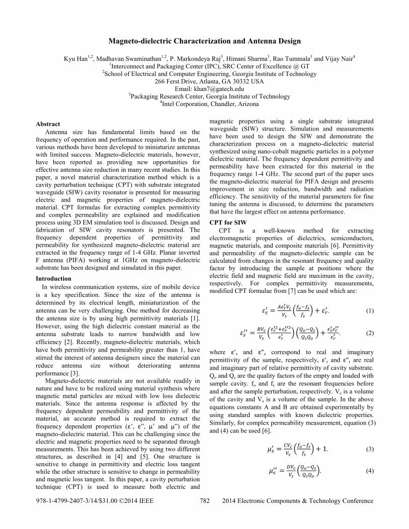
Magneto-dielectric Characterization and Antenna Design
Kyu Han
1,2, Madhavan Swaminathan
1,2, P. Markondeya Raj
3, Himani Sharma
3, Rao Tummala
3 and Vijay Nair
4
1Interconnect and Packaging Center (IPC), SRC Center of Excellence @ GT
2School of Electrical and Computer Engineering, Georgia Institute of Technology
266 Ferst Drive, Atlanta, GA 30332 USA
Email: [email protected] 3Packaging Research Center, Georgia Institute of Technology
4Intel Corporation, Chandler, Arizona
Abstract
Antenna size has fundamental limits based on the
frequency of operation and performance required. In the past,
various methods have been developed to miniaturize antennas
with limited success. Magneto-dielectric materials, however,
have been reported as providing new opportunities for
effective antenna size reduction in many recent studies. In this
paper, a novel material characterization method which is a
cavity perturbation technique (CPT) with substrate integrated
waveguide (SIW) cavity resonator is presented for measuring
electric and magnetic properties of magneto-dielectric
material. CPT formulas for extracting complex permittivity
and complex permeability are explained and modification
process using 3D EM simulation tool is discussed. Design and
fabrication of SIW cavity resonators is presented. The
frequency dependent properties of permittivity and
permeability for synthesized magneto-dielectric material are
extracted in the frequency range of 1-4 GHz. Planar inverted
F antenna (PIFA) working at 1GHz on magneto-dielectric
substrate has been designed and simulated in this paper.
Introduction
In wireless communication systems, size of mobile device
is a key specification. Since the size of the antenna is
determined by its electrical length, miniaturization of the
antenna can be very challenging. One method for decreasing
the antenna size is by using high permittivity materials [1].
However, using the high dielectric constant material as the
antenna substrate leads to narrow bandwidth and low
efficiency [2]. Recently, magneto-dielectric materials, which
have both permittivity and permeability greater than 1, have
stirred the interest of antenna designers since the material can
reduce antenna size without deteriorating antenna
performance [3].
Magneto-dielectric materials are not available readily in
nature and have to be realized using material synthesis where
magnetic metal particles are mixed with low loss dielectric
materials. Since the antenna response is affected by the
frequency dependent permeability and permittivity of the
material, an accurate method is required to extract the
frequency dependent properties (ε’, ε”, μ’ and μ”) of the
magneto-dielectric material. This can be challenging since the
electric and magnetic properties need to be separated through
measurements. This has been achieved by using two different
structures, as described in [4] and [5]. One structure is
sensitive to change in permittivity and electric loss tangent
while the other structure is sensitive to change in permeability
and magnetic loss tangent. In this paper, a cavity perturbation
technique (CPT) is used to measure both electric and
magnetic properties using a single substrate integrated
waveguide (SIW) structure. Simulation and measurements
have been used to design the SIW and demonstrate the
characterization process on a magneto-dielectric material
synthesized using nano-cobalt magnetic particles in a polymer
dielectric material. The frequency dependent permittivity and
permeability have been extracted for this material in the
frequency range 1-4 GHz. The second part of the paper uses
the magneto-dielectric material for PIFA design and presents
improvement in size reduction, bandwidth and radiation
efficiency. The sensitivity of the material parameters for fine
tuning the antenna is discussed, to determine the parameters
that have the largest effect on antenna performance.
CPT for SIW
CPT is a well-known method for extracting
electromagnetic properties of dielectrics, semiconductors,
magnetic materials, and composite materials [6]. Permittivity
and permeability of the magneto-dielectric sample can be
calculated from changes in the resonant frequency and quality
factor by introducing the sample at positions where the
electric field and magnetic field are maximum in the cavity,
respectively. For complex permittivity measurements,
modified CPT formulae from [7] can be used which are:
(
)
. (1)
(
) (
)
. (2)
where ε’s and ε”s correspond to real and imaginary
permittivity of the sample, respectively, ε’r and ε”r are real
and imaginary part of relative permittivity of cavity substrate.
Qo and Qs are the quality factors of the empty and loaded with
sample cavity. fo and fs are the resonant frequencies before
and after the sample perturbation, respectively. Vc is a volume
of the cavity and Vs is a volume of the sample. In the above
equations constants A and B are obtained experimentally by
using standard samples with known dielectric properties.
Similarly, for complex permeability measurement, equation (3)
and (4) can be used [6].
(
) . (3)
(
). (4)
978-1-4799-2407-3/14/$31.00 ©2014 IEEE 782 2014 Electronic Components & Technology Conference
where μ’s and μ”s are real and imaginary part of permeability
of the sample where constants C and D in equations (3) and (4)
are also obtained from the measurement of standard sample.
Design of SIW Cavities and CPT Analysis
SIW technology has been used to implement cavities for
CPT in this paper, as shown in Fig. 1, since they have high Q,
are highly sensitive to material properties and have minimum
radiation effect. This technology has been used to measure
complex permittivity of dielectric materials in [7] and [8]. The
resonant frequency of these resonators for TEm0k mode is
related to the width W and the length L of the cavity as
follows [7]:
√
√(
) (
) (5)
where c is the speed of light in free space, ε’r and μ’r are the
relative permittivity and permeability of SIW substrate
respectively and m, k are mode numbers.
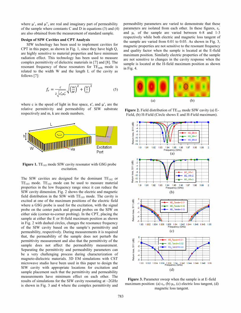
Figure 1. TE103 mode SIW cavity resonator with GSG probe
excitation.
The SIW cavities are designed for the dominant TE102 or
TE103 mode. TE102 mode can be used to measure material
properties in the low frequency range since it can reduce the
SIW cavity dimension. Fig. 2 shows the electric and magnetic
field distribution in the SIW with TE103 mode. The cavity is
excited at one of the maximum positions of the electric field
where a GSG probe is used for the excitation, with the signal
probe on the center patch and ground probes on the SIW on
either side (corner-to-corner probing). In the CPT, placing the
sample at either the E or H-field maximum position as shown
in Fig. 2 with dashed circles, changes the resonance frequency
of the SIW cavity based on the sample’s permittivity and
permeability, respectively. During measurements it is required
that, the permeability of the sample does not perturb the
permittivity measurement and also that the permittivity of the
sample does not affect the permeability measurement.
Separating the permittivity and permeability parameters can
be a very challenging process during characterization of
magneto-dielectric materials. 3D EM simulations with CST
microwave studio have been used in this paper to design the
SIW cavity with appropriate locations for excitation and
sample placement such that the permittivity and permeability
measurements have minimum effect on each other. The
results of simulations for the SIW cavity resonating at ~2GHz
is shown in Fig. 3 and 4 where the complex permittivity and
permeability parameters are varied to demonstrate that these
parameters are isolated from each other. In these figures, εr’
and μr’ of the sample are varied between 6-8 and 1-3
respectively while both electric and magnetic loss tangent of
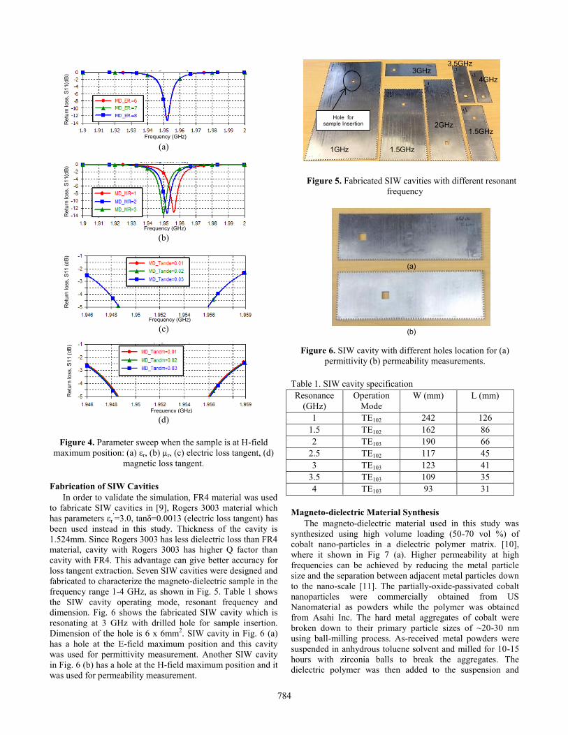
the sample are varied from 0.01 to 0.03. As shown in Fig. 3,
magnetic properties are not sensitive to the resonant frequency
and quality factor when the sample is located at the E-field
maximum position. Similarly electric properties of the sample
are not sensitive to changes in the cavity response when the
sample is located at the H-field maximum position as shown
in Fig. 4.
(a) (b)
Figure 2. Field distribution of TE103 mode SIW cavity (a) E-
Field, (b) H-Field (Circle shows E and H-Field maximum).
(a)
(b)
(c)
(d)
Figure 3. Parameter sweep when the sample is at E-field
maximum position: (a) εr, (b) µr, (c) electric loss tangent, (d)
magnetic loss tangent.
Re
turn
lo
ss,
S1
1 (
dB
)
Frequency (GHz)
Frequency (GHz)
Re
turn
lo
ss,
S1
1 (
dB
)
Frequency (GHz)
Re
turn
lo
ss,
S1
1 (
dB
)
Frequency (GHz)
Re
turn
lo
ss,
S1
1 (
dB
)
783
(a)
(b)
(c)
(d)
Figure 4. Parameter sweep when the sample is at H-field
maximum position: (a) εr, (b) µr, (c) electric loss tangent, (d)
magnetic loss tangent.
Fabrication of SIW Cavities
In order to validate the simulation, FR4 material was used
to fabricate SIW cavities in [9], Rogers 3003 material which
has parameters εr’=3.0, tanδ=0.0013 (electric loss tangent) has
been used instead in this study. Thickness of the cavity is
1.524mm. Since Rogers 3003 has less dielectric loss than FR4
material, cavity with Rogers 3003 has higher Q factor than
cavity with FR4. This advantage can give better accuracy for
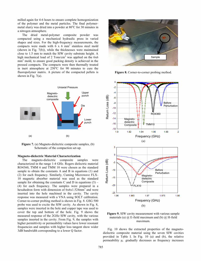
loss tangent extraction. Seven SIW cavities were designed and
fabricated to characterize the magneto-dielectric sample in the
frequency range 1-4 GHz, as shown in Fig. 5. Table 1 shows
the SIW cavity operating mode, resonant frequency and
dimension. Fig. 6 shows the fabricated SIW cavity which is
resonating at 3 GHz with drilled hole for sample insertion.
Dimension of the hole is 6 x 6mm2. SIW cavity in Fig. 6 (a)
has a hole at the E-field maximum position and this cavity
was used for permittivity measurement. Another SIW cavity
in Fig. 6 (b) has a hole at the H-field maximum position and it
was used for permeability measurement.
Figure 5. Fabricated SIW cavities with different resonant
frequency
Figure 6. SIW cavity with different holes location for (a)
permittivity (b) permeability measurements.
Table 1. SIW cavity specification
Resonance
(GHz)
Operation
Mode
W (mm) L (mm)
1 TE102 242 126
1.5 TE102 162 86
2 TE103 190 66
2.5 TE102 117 45
3 TE103 123 41
3.5 TE103 109 35
4 TE103 93 31
Magneto-dielectric Material Synthesis
The magneto-dielectric material used in this study was
synthesized using high volume loading (50-70 vol %) of
cobalt nano-particles in a dielectric polymer matrix. [10],
where it shown in Fig 7 (a). Higher permeability at high
frequencies can be achieved by reducing the metal particle
size and the separation between adjacent metal particles down
to the nano-scale [11]. The partially-oxide-passivated cobalt
nanoparticles were commercially obtained from US
Nanomaterial as powders while the polymer was obtained
from Asahi Inc. The hard metal aggregates of cobalt were
broken down to their primary particle sizes of ~20-30 nm
using ball-milling process. As-received metal powders were
suspended in anhydrous toluene solvent and milled for 10-15
hours with zirconia balls to break the aggregates. The
dielectric polymer was then added to the suspension and
Re
turn
lo
ss,
S1
1(d
B)
Frequency (GHz)
Frequency (GHz)
Re
turn
lo
ss,
S1
1(d
B)
Re
turn
lo
ss,
S1
1 (
dB
)
Frequency (GHz)
Re
turn
lo
ss,
S1
1 (
dB
)
Frequency (GHz)
1.5GHz
1.5GHz
3.5GHz
1GHz
4GHz 3GHz
2GHz Hole for
sample Insertion
(a)
(b)
784
milled again for 4-6 hours to ensure complete homogenization
of the polymer and the metal particles. The final polymer-
metal slurry was dried into a powder at 80oC for 30 minutes in
a nitrogen atmosphere.
The dried metal-polymer composite powder was
compacted using a mechanical hydraulic press in varied
shapes and sizes. For the high-frequency measurements, the
compacts were made with 6 x 6 mm2 stainless steel mold
(shown in Fig. 7(b)), while the thicknesses were maintained
close to 1.5 mm to match the SIW cavity substrate height. A
high mechanical load of 2 Tons/cm2 was applied on the 6x6
mm2 mold, to ensure good packing density is achieved in the
pressed compacts. The compacts were then thermally treated
in inert atmosphere at 250oC for 90 minutes to cure the
fluoropolymer matrix. A picture of the compacted pellets is
shown in Fig. 7(a).
Figure 7. (a) Magneto-dielectric composite samples, (b)
Schematic of the compaction set-up.
Magneto-dielectric Material Characterization
The magneto-dielectric composite samples were
characterized in the range 1-4 GHz. Rogers dielectric material
RO4360, TMM 6 and TMM 10 were chosen as the standard
sample to obtain the constants A and B in equations (1) and
(2) for each frequency. Similarly, Cuming Microwave FLX-
10 magnetic absorber material was used as the standard
sample for obtaining the constants C and D in equations (3) –
(4) for each frequency. The samples were prepared in a
hexahedron form with dimension of 6x6x1.524mm3 and were
inserted into the hole machined in the cavity. The cavity
response was measured with a VNA using SOLT calibration.
Corner-to-corner probing method is shown in Fig. 8. GSG 500
probe was used to excite the SIW cavity. As shown in Fig. 8,
samples were inserted in the hole and copper tape was used to
cover the top and bottom of the hole. Fig. 9 shows the
measured response of the 2GHz SIW cavity, with the various
samples inserted in the cavity. From Fig. 9, the samples with
higher permittivity or permeability values have lower resonant
frequencies and samples with higher loss tangent show wider
3dB bandwidth corresponding to a lower Q factor.
Figure 8. Corner-to-corner probing method.
(a)
(b)
Figure 9. SIW cavity measurement with various sample
materials (a) @ E-field maximum and (b) @ H-field
maximum.
Fig. 10 shows the extracted properties of the magneto-
dielectric composite material using the seven SIW cavities
provided in Table I. In Fig. 10 (a) and (b), the relative
permeability μr’ gradually decreases as frequency increases
Frequency (GHz)
Re
turn
Loss (
dB
)
Before Perturbation
RO4360
TMM10
Magneto-dielectric Composite
Frequency (GHz)
Re
turn
Loss (
dB
)
Before Perturbation
Magneto-dielectric Composite
FLX10
Uniaxial Pressure
Upper punch
Lower punch
Die
Magneto-dielectric
composite
(a) (b)
Sample
785
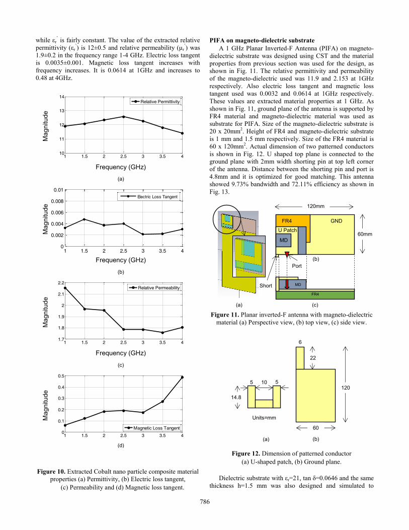
while εr’ is fairly constant. The value of the extracted relative
permittivity (εr’) is 12±0.5 and relative permeability (μr
’) was
1.9±0.2 in the frequency range 1-4 GHz. Electric loss tangent
is 0.0035±0.001. Magnetic loss tangent increases with
frequency increases. It is 0.0614 at 1GHz and increases to
0.48 at 4GHz.
Figure 10. Extracted Cobalt nano particle composite material
properties (a) Permittivity, (b) Electric loss tangent,
(c) Permeability and (d) Magnetic loss tangent.
PIFA on magneto-dielectric substrate
A 1 GHz Planar Inverted-F Antenna (PIFA) on magneto-
dielectric substrate was designed using CST and the material
properties from previous section was used for the design, as
shown in Fig. 11. The relative permittivity and permeability
of the magneto-dielectric used was 11.9 and 2.153 at 1GHz
respectively. Also electric loss tangent and magnetic loss
tangent used was 0.0032 and 0.0614 at 1GHz respectively.
These values are extracted material properties at 1 GHz. As
shown in Fig. 11, ground plane of the antenna is supported by
FR4 material and magneto-dielectric material was used as
substrate for PIFA. Size of the magneto-dielectric substrate is
20 x 20mm2. Height of FR4 and magneto-dielectric substrate
is 1 mm and 1.5 mm respectively. Size of the FR4 material is
60 x 120mm2. Actual dimension of two patterned conductors
is shown in Fig. 12. U shaped top plane is connected to the
ground plane with 2mm width shorting pin at top left corner
of the antenna. Distance between the shorting pin and port is
4.8mm and it is optimized for good matching. This antenna
showed 9.73% bandwidth and 72.11% efficiency as shown in
Fig. 13.
Figure 11. Planar inverted-F antenna with magneto-dielectric
material (a) Perspective view, (b) top view, (c) side view.
Figure 12. Dimension of patterned conductor
(a) U-shaped patch, (b) Ground plane.
Dielectric substrate with εr=21, tan δ=0.0646 and the same
thickness h=1.5 mm was also designed and simulated to
FR4
MD
(a)
(b)
(c)
Port
Short
GND FR4
U Patch
MD
120mm
60mm
5 5 10
14.8
6
22
60
120
Units=mm
(b) (a)
Frequency (GHz)
(a)
1 1.5 2 2.5 3 3.5 410
11
12
13
14
Relative Permittivity
Mag
nitu
de
Frequency (GHz)
(b)
Mag
nitu
de
1 1.5 2 2.5 3 3.5 41.7
1.8
1.9
2
2.1
2.2
Relative Permeability
Frequency (GHz)
(c)
Mag
nitu
de
1 1.5 2 2.5 3 3.5 40
0.1
0.2
0.3
0.4
0.5
Magnetic Loss Tangent
Mag
nitu
de
(d)
1 1.5 2 2.5 3 3.5 40
0.002
0.004
0.006
0.008
0.01
Electric Loss Tangent
786
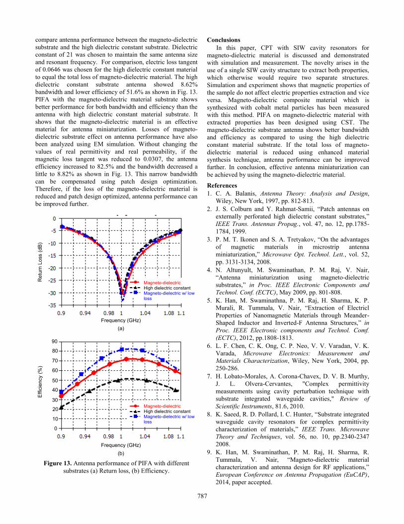
compare antenna performance between the magneto-dielectric
substrate and the high dielectric constant substrate. Dielectric
constant of 21 was chosen to maintain the same antenna size
and resonant frequency. For comparison, electric loss tangent
of 0.0646 was chosen for the high dielectric constant material
to equal the total loss of magneto-dielectric material. The high
dielectric constant substrate antenna showed 8.62%
bandwidth and lower efficiency of 51.6% as shown in Fig. 13.
PIFA with the magneto-dielectric material substrate shows
better performance for both bandwidth and efficiency than the
antenna with high dielectric constant material substrate. It
shows that the magneto-dielectric material is an effective
material for antenna miniaturization. Losses of magneto-
dielectric substrate effect on antenna performance have also
been analyzed using EM simulation. Without changing the
values of real permittivity and real permeability, if the
magnetic loss tangent was reduced to 0.0307, the antenna
efficiency increased to 82.5% and the bandwidth decreased a
little to 8.82% as shown in Fig. 13. This narrow bandwidth
can be compensated using patch design optimization.
Therefore, if the loss of the magneto-dielectric material is
reduced and patch design optimized, antenna performance can
be improved further.
Figure 13. Antenna performance of PIFA with different
substrates (a) Return loss, (b) Efficiency.
Conclusions
In this paper, CPT with SIW cavity resonators for
magneto-dielectric material is discussed and demonstrated
with simulation and measurement. The novelty arises in the
use of a single SIW cavity structure to extract both properties,
which otherwise would require two separate structures.
Simulation and experiment shows that magnetic properties of
the sample do not affect electric properties extraction and vice
versa. Magneto-dielectric composite material which is
synthesized with cobalt metal particles has been measured
with this method. PIFA on magneto-dielectric material with
extracted properties has been designed using CST. The
magneto-dielectric substrate antenna shows better bandwidth
and efficiency as compared to using the high dielectric
constant material substrate. If the total loss of magneto-
dielectric material is reduced using enhanced material
synthesis technique, antenna performance can be improved
further. In conclusion, effective antenna miniaturization can
be achieved by using the magneto-dielectric material.
References
1. C. A. Balanis, Antenna Theory: Analysis and Design,
Wiley, New York, 1997, pp. 812-813.
2. J. S. Colburn and Y. Rahmat-Samii, “Patch antennas on
externally perforated high dielectric constant substrates,”
IEEE Trans. Antennas Propag., vol. 47, no. 12, pp.1785-
1784, 1999.
3. P. M. T. Ikonen and S. A. Tretyakov, “On the advantages
of magnetic materials in microstrip antenna
miniaturization,” Microwave Opt. Technol. Lett., vol. 52,
pp. 3131-3134, 2008.
4. N. Altunyult, M. Swaminathan, P. M. Raj, V. Nair,
“Antenna miniaturization using magneto-dielectric
substrates,” in Proc. IEEE Electronic Components and
Technol. Conf. (ECTC), May 2009, pp. 801-808.
5. K. Han, M. Swaminathna, P. M. Raj, H. Sharma, K. P.
Murali, R. Tummala, V. Nair, “Extraction of Electricl
Properties of Nanomagnetic Materials through Meander-
Shaped Inductor and Inverted-F Antenna Structures,” in
Proc. IEEE Electronic components and Technol. Comf.
(ECTC), 2012, pp.1808-1813.
6. L. F. Chen, C. K. Ong, C. P. Neo, V. V. Varadan, V. K.
Varada, Microwave Electronics: Measurement and
Materials Characterization, Wiley, New York, 2004, pp.
250-286.
7. H. Lobato-Morales, A. Corona-Chavex, D. V. B. Murthy,
J. L. Olvera-Cervantes, "Complex permittivity
measurements using cavity perturbation technique with
substrate integrated waveguide cavities," Review of
Scientific Instruments, 81.6, 2010.
8. K. Saeed, R. D. Pollard, I. C. Hunter, “Substrate integrated
waveguide cavity resonators for complex permittivity
characterization of materials,” IEEE Trans. Microwave
Theory and Techniques, vol. 56, no. 10, pp.2340-2347
2008.
9. K. Han, M. Swaminathan, P. M. Raj, H. Sharma, R.
Tummala, V. Nair, “Magneto-dielectric material
characterization and antenna design for RF applications,”
European Conference on Antenna Propagation (EuCAP),
2014, paper accepted.
Retu
rn L
oss (
dB
)
Frequency (GHz) (a)
90
80
70
60
50
40
30
20
10
0
Effic
iency (
%)
Frequency (GHz) (b)
Magneto-dielectric High dielectric constant Magneto-dielectric w/ low loss
Magneto-dielectric High dielectric constant Magneto-dielectric w/ low loss
787
10. P. M. Raj, H. Sharma, D. Mishra, K. P. Murali, K. Han, M.
Swaminathan, R. Tummala, “Nanomagnetics for high-
performance, miniaturized power, and RF components,”
IEEE Nanotechnology magazine, vol. 6, no. 3, pp.18-23
2012.
11. N. Tang, W. Zhong, X. Wu, H. Jiang, W. Liu, and Y. Du,
“Synthesis and complex permeability of Co/SiO2
nanocomposites,” Matter. Lett., vol. 59, no. 14-15,
pp.1723-1726, 2005.
788