Embed Size (px)
Citation preview

IISSSSUUEE 2200 -- FFEEBB 22001144
AA MMaaggaazziinnee ffoorr RRaassppbbeerrrryy PPii UUsseerrss
hhttttpp::////wwwwww..tthheemmaaggppii..ccoommRRaassppbbeerrrryy PPii iiss aa ttrraaddeemmaarrkk ooff TThhee RRaassppbbeerrrryy PPii FFoouunnddaattiioonn..TThhiiss mmaaggaazziinnee wwaass ccrreeaatteedd uussiinngg aa RRaassppbbeerrrryy PPii ccoommppuutteerr..
GGeett pprriinntteedd ccooppiieess
aatt tthheemmaaggppii..ccoomm
Resolve Cable Modem 'Flap'
Environmental Monitor
Panoramic Photos
RReemmoottee SSeennssiinngg
QQuuaaddccoopptteerr
Scratch II//OO
BBaarree MMeettaall
AAllggooiidd
PPiiBBOOXXRRaassppbbeerrrryy PPii hhoossttiinngg
Win aGEEKcase,
Pi NoIR camera,GPIO Cobbler,2 SD cards& more

Ash Stone - Chief Editor / Administration / Layout
W.H. Bell - Issue Editor / Layout / Grapics / Administration
Bryan Butler - Page Design / Graphics
Ian McAlpine - Layout / Proof Reading
Matt Judge - Website / Administration
Aaron Shaw - Layout / Proof Reading
Colin Deady - Layout / Proof Reading
The MagPi Team
Chris 'tzj' Stagg - Graphics
Claire Price - Layout / Proof Reading
Amy-Clare Martin - Layout
Nigel Curtis - Proof Reading
Bulent Tuncel - Layout / Testing / Proof Reading
James Nelson - Testing / Proof Reading
Age-Jan (John) Stap - Layout
2
20
Welcome to Issue 20 of The MagPi magazine. I t’s a brand new year and we can’t wait to seewhat is in store for the Raspberry Pi over the next 1 2 months.
After a massive response, we are pleased to write that the article series ‘Bake your own Pi fi l l ing’ isback by popular demand! In this article Martin Kalitis throws down the gauntlet by instructing how tocreate a bootable Linux SD card which can load within 1 0 seconds.
We have more from the Caribbean with Project Curacao. This project has been so popular with ourreaders that John Shovic is extending it further, in a future issue, with a conclusion presenting theproject's results. In this issue John reviews the bui lding and instal lation of the camera and shuttermount into the project, al lowing the production of timed photos, before updating us on changes made tothe project from past articles.
Deepak Pati l introduces his project for panoramic photography using Pi-Pan, a robotic arm control ledby his Raspberry Pi to move his Pi Camera. Deepak looks at some of the code used to control thisclever kit and discusses how to take pictures while out in your car.
We have more from Andy Baker’s Quadcopter series with this issue reviewing his pre-fl ight checks. Hisarticle looks at control l ing the movement of the Quadcopter and provides some handy questions andanswers for those of you who have been bui lding this project.
We have a great article detai l ing John Hobson’s and Efrain Olivares’ journey into managing thefrustrating problem of internet dropout. We then head over to France where Yann Caron presents hisdevelopment environment and language ‘Algoid’ , before the NanoXion chaps present their Raspberry Picolocation service.
As always, we keep you updated with the latestRaspberry Pi book reviews and upcoming events.
Let's begin.. .
Chief Editor of The MagPi

3
4 PROJECT CURACAO: REMOTE SENSOR MONITORING IN THE CARIBBEANPart 3: The camera subsystem
8A pan and ti l t control for your Raspberry Pi camera
PROGRAMMING FOR PI-PAN
Part 2: Pre-fl ight checks1 0 QUADCOPTER
1 9Win a Pi NoIR camera, GPIO breakout, gigabit hub, two SD cards and moreCOMPETITION
20Using a Raspberry Pi to automatical ly restore a lost internet connectionCABLE MODEM
26RACKS OF PIColocating Raspberry Pi 's in France
29 THIS MONTH'S EVENTS GUIDECambridge UK, Malvern UK, Mountain View California USA, Manchester UK, Southend-on-Sea UK
ENVIRONMENTAL MONITORPart 2: Using the Google Chart l ibrary to visual ise data
1 6
30Programming made simple and funALGOID
44Have your say about The MagPiFEEDBACK
Python in Easy Steps and Raspberry Pi Networking CookbookBOOK REVIEWS43
40Part 2: Bake your own Pi fi l l ing - bui ld tools and moreMY OS: BUILD A CUSTOMISED OPERATING SYSTEM
36Flexible I/O: using GPIO, SPI, fi les & moreTHE SCRATCH PATCH
http://www.themagpi.com
ContentsContentsContents

4
SKILL LEVEL : INTERMEDIATE
John Shovic
Guest Writer
PROJECT CURACAORemote sensor monitoring in the Caribbean
Part 3: The camera subsystem
What is Project Curacao?
This is the third part of a series discussing the
design and bui lding of Project Curacao, a sensor
fi l led project that wil l hang on a radio tower on the
island nation of Curacao. Curacao is a desert
island 1 2 degrees north of the equator in the
Caribbean. Original ly intended for four issues this
series wil l now be extended to cover the results of
the instal lation in a later issue of The MagPi.
Project Curacao is designed to monitor the local
environment unattended for six months. I t operates
on solar power cel ls and wil l communicate with the
designer via an iPad App called RasPiConnect. Al l
aspects of this project are designed to be
monitored remotely. Below is a picture of the tower
where it wi l l be instal led in March 201 4.
System description
Project Curacao consists of four subsystems. A
Raspberry Pi Model A is the brains and the overal l
control ler. The Power Subsystem was described in
part 1 and the Environmental Sensor Subsystem
was described in part 2. The Camera Subsystem
consists of a Raspberry Pi Camera and a servo
motor that opens and closes a "shutter" that is
intended to keep salt spray and dirt from coating
the plexiglass over the camera.

5
What hardware will be used?
1 Raspberry Pi Camera
1 Adafruit Analog Feedback Servo Motor
1 Adafruit ADS1 01 5 1 2-Bit ADC - 4 Channel I2C
1 Tidy Cat plastic l id for shutter
Camera and Shutter Mount
We assembled the camera mount from soft plastic
and superglue. I t was designed to sit just under
the plexiglass. Initial ly, we tried to mount it on top
of the plexiglass, but had a very difficult time with
the short fragi le cable to the Raspberry Pi. The
shutter and the servo motor completes the device.
Camera Software
The Pi Camera software turned out to be quite
simple. The important part of the Python module to
take a picture turned out to be only a few lines:
We started out using the picamera l ibrary
(https://pypi.python.org/pypi/picamera) because it
was pure Python and feature heavy. We removed
it and went back to raspisti l l (as above) because of
a GPIO line confl ict with the RPIO GPIO library.
We wanted to use the RPIO library because it
supports DMA (Direct Memory Address - this
means it works with no intervention from the CPU,
thus multitasking has no effect) driven PWM (Pulse
Width Modulation) for the servo motor, but it is
NOT compatible with picamera.
We uninstal led the RPIO library and put the latest
RPi.GPIO library back in and used their software
based PWM. While it is j i ttery (because of the
multi-tasking Linux on the Raspberry Pi) , we are
using a servo with a feedback potentiometer for
position feedback. We check the shutter position
after using the RPi.GPIO PWM library by
performing an A/D conversion of the pot voltage
using the ADS1 05. We can then see the position
of the servo and run the PWM again unti l i t is within
the bounds of the shutter being open or closed.
With this feedback, we can accurately position the
shutter even with the j ittery response due to multi-
tasking.
Timed Photos
Currently, the Project Curacao main software
(described in the upcoming part 4), takes a picture
every hour and on demand from the control
program RasPiConnect. We can even email
pictures on demand using our control panel. A
crontab entry transfers the latest picture to a server
in the US using scp so we have a
prototype external webpage showing
the current status of Project Curacao.
The webpage is being hosted by our
good friends at MiloCreek (developer
of RasPiConnect) and the address is:
http://mi locreek.com/projectcuracaogr
aphs.
Future functions
We are planning to add three
additional features to the Camera
Subsystem. These are time lapse
photography, a short video on demand
and a streaming video interface. A big
unknown for the streaming video
interface is the amount of bandwidth
avai lable for uploading data in Curacao. We know
that it is an ADSL modem, but we don't know the
parameters on the upload speeds.
def takePicture(source):# take pictureprint "taking picture"output = subprocess.check_output ("raspistill -o
/home/pi/RasPiConnectServer/static/picameraraw.jpg-t 0",shell=True, stderr=subprocess.STDOUT )
output = subprocess.check_output("convert'/home/pi/RasPiConnectServer/static/picameraraw.jpg' -pointsize 72 -fill white -gravity SouthWest-annotate +50+100 'ProjectCuracao%[exif:DateTimeOriginal]''/home/pi/RasPiConnectServer/static/picamera.jpg'",shell=True, stderr=subprocess.STDOUT)
pclogging.log(pclogging.INFO, __name__, source )print "finished taking picture"return

6
Camera Shutter Cover Servomotor
The camera shutter cover is designed to keep the
majority of dirt and sea spray off the plexiglass in
front of the Pi Camera. I t uses an analog feedback
servo motor so we always know where the shutter
is regardless of multitasking or unexpected power
downs.
Control Panel
The RasPiConnect control panel shows the current
luminosity and the analog position of the servo
motor. I t also al lows you to take pictures, open and
close the shutter and email the current picture. The
graph shows the status of the Raspberry Pi OS
and of the Project Curacao and
RasPiConnectServer software.
Updates on previous articles
Relays
The fan relay and the Raspberry Pi relay have
been replaced with latching relays that consume no
power after they have been switched. This saves
60ma. We used http://shop.ciseco.co.uk/3v-to-5v-
bistable-latching-relay-kit/. Thank you to Paul
Carpenter for the excel lent suggestion.
Environmental Sensors
We are adding a pitot tube with sensor to measure
airspeed, using the Airspeed Sensor Kit
from http://robotshop.com. Alternatively, we are
looking at using the open loop voltage of the wind
turbine to approximate the windspeed (see
http://switchdoc.blogspot.com). I t looks l ike it wi l l
work up to wind speeds of about 50 MPH.
BatteryWatchdog System
The Battery Watch Arduino software has expanded
to about 3000 lines of code. There are certainly
bugs in this software. One of the unresolved
issues about the architecture of Project Curacao is
that the software on the Raspberry Pi can be easi ly
updated remotely across the Internet whi le the
software on the Battery Watchdog Arduino can not
be updated. This is because there is no current
way of updating the Arduino without plugging in a
USB serial port. While we are investigating options
(different boot loader, figuring out a way of using
the USB port on the Raspberry Pi for
programming) we are looking at connecting the
Raspberry Pi to make our system just a bit more
resi l ient than it currently is.
To partial ly address this problem we are going to
bui ld what is cal led a "Dead Man Switch" in
software. I f the Raspberry Pi has been off for two
days, then the Battery Watchdog wil l turn it on. This
helps us recover from many types of errors in the
Battery Watchdog software.
We also ran into a very subtle bug using the Serial
l ibrary in the Arduino. We are using two serial
ports (the main USB port and a second UART
talking to the Raspberry Pi) . I f both ports aren't set
to the same baud rate, then they stop working after
a while. With the baud rates matched, everything
is very sol id.
PowerSystem Update
We have found an inexpensive 1 5 Watt wind
turbine to add to the system. This could very well
charge our system enough to not have to shutdown
at night. More on how we are hooking up the
turbine into and control l ing it via the Raspberry Pi
next month.
What is coming Up?
Part 4 of this article describes the software system
used for Project Curacao. Part 5 wil l describe the
process of instal l ing the unit in Curacao and show
the first weeks of results. Al l of the code used in
this article is posted on GitHub at
http://github.com/projectcuracao.
More discussion on Project Curacao at:
http://switchdoc.blogspot.com
8
SKILL LEVEL : INTERMEDIATE
Deepak Patil
Guest Writer
PROGRAMMING PI-PANPanoramic photography
A pan and tilt control for your
Raspberry Pi camera
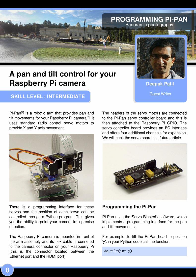
Pi-Pan [1 ] is a robotic arm that provides pan and
ti l t movements for your Raspberry Pi camera[2]. I t
uses standard radio control servo motors to
provide X and Y axis movement.
There is a programming interface for these
servos and the position of each servo can be
control led through a Python program. This gives
you the abi l i ty to point your camera in a precise
direction.
The Raspberry Pi camera is mounted in front of
the arm assembly and its flex cable is conneted
to the camera connector on your Raspberry Pi
(this is the connector located between the
Ethernet port and the HDMI port) .
The headers of the servo motors are connected
to the Pi-Pan servo control ler board and this is
then attached to the Raspberry Pi GPIO. The
servo control ler board provides an I2C interface
and offers four additional channels for expansion.
We wil l hack the servo board in a future article.
Programming the Pi-Pan
Pi-Pan uses the Servo Blaster[3] software, which
implements a programming interface for the pan
and ti l t movements.
For example, to ti l t the Pi-Pan head to position
'y', in your Python code call the function:
do_tilt(int y)

9
The parameter 'y' is the ti l t (vertical) position of
Pi-Pan ranging from 80 to 220, where:
80 = looking down
220 = looking up
1 50 = straight ahead (neutral position)
To pan the Pi-Pan head to position 'x', in your
Python code call the function:
do_pan(int x)
The parameter 'x' is the pan (horizontal) position
of Pi-Pan ranging from 50 to 250, where:
50 = looking left
250 = looking right
1 50 = straight ahead (neutral position)
To control individual servos, in your Python code
call the function:
pwm(int pin, int position)
The parameter 'pin' is the pin number of the
servo motor you want to control. Values range
from S0 to S5.
The parameter 'position' is the desired
destination position for the servo motor. Values
range from 50 to 250.
Synchronized picture taking andcamera movements with Python
To make a panoramic picture using Pi-Pan you
take overlapping pictures from a fixed position,
rotating the camera about a single axis, and then
join the pictures using stitching software such as
AutoStitch [4].
The fol lowing Python code wil l take pictures to
make a panorama:
for pan in xrange(50, 226, 25):
p. do_pan (int(pan))
time. sleep(1)
cmdstr = "/var/tmp/pic_" + str(pan) +
" . jpg"
# Take the picture.
subprocess. call(["raspistill" , "-o" ,
cmdstr, "-rot", "180"] )
This code starts the Pi-Pan servo motor at the
left-most position (50) and steps through
increments of 25 unti l i t reaches the last position
(225), just short of the right-most position (250).
At each step the servo stops momentari ly and a
picture is taken. Al l the pictures are stored in the
/var/tmp folder.
The image above is an example of what can be
achieved with the Pi-Pan.
Tips for shooting outdoors from a car
1 ) You can power the Raspberry Pi from your
car's cigarette l ighter port via a suitable USB
adapter.
2) Before you leave home, setup a script on the
Raspberry Pi such that when it is powered on it
wi l l automatical ly start shooting pictures. You can
set this up in the /etc/init. d folder.
3) While shooting you can just rest the Raspberry
Pi on the side view mirror and hold it steady.
4) Don't start the engine while the Raspberry Pi
is running. Most cars cut off power to the
cigarette l ighter port whi le starting the engine.
References[1 ] Pi-Pan: http://www.openelectrons.com/Pi-Pan
[2] Camera: http://www.raspberrypi.org/camera
[3] ServoBlaster: https://github.com/richardghirst/PiBits
[4] AutoStitch: http://www.cs.bath.ac.uk/brown/autostitch/
autostitch.html

1 0
SKILL LEVEL : ADVANCED
Andy Baker
Guest Writer
Quadcopter pre-flight checks
[Ed: This is an advanced skill level article. It isnot a step-by-step guide for beginners.Quadcopters are dangerous. They can causedamage and serious injury. Be responsible,educate yourself and take precautions to protecteverything and everyone in the vicinity.]
In Issue 1 9 I presented a high-level overview of how to
bui ld your own quadcopter using a Raspberry Pi as the
fl ight-control ler. However, there were lots of detai ls missing
in that article about tuning and testing the settings for your
quadcopter. This article fi l ls in those blanks.
Some prerequisites…
These tests cannot be powered from a wire – you need a
ful ly charged battery attached to your quadcopter. Unl ike
the rest of the world where duct tape is "the force", with
quadcopters it seems to be velcro! Use it generously to
make sure everything is securely attached.
Connect to yourquadcopter
Your quadcopter needs Wi-Fi. You need another machine
(Raspberry Pi, Windows or Linux) that can open a secure
shel l and log into your quadcopter Raspberry Pi. I use an
iPad with WebSSH or rlogin from one of my other
Raspberry Pi 's depending on where the testing is
happening.
Get the latest code
This project is sti l l l ive and the code changes regularly.
Make sure you have the latest software, which is avai lable
at https://github.com/PiStuffing/Quadcopter. Copy the
software into your home directory, e.g. /home/pi .
The command-line
The quadcopter Python code qc. py has various
command-l ine parameters which control i ts testing and
fl ights. Here’s the complete l ist. We’ l l go through these in
detai l throughout the article. To run your quadcopter, at the
command prompt where the code lives, type:
sudo python . /qc. py
The fol lowing is a l ist of the avai lable parameters:
-f – fly the quad
-v – run the video
-g – calibrate gravity
-h XXXX – set the PWM pulse width for hover
--tc # – run test case number #
--hvp XXXX – horizontal velocity PID P gain
--hvi XXXX – horizontal velocity PID I gain
--hvd XXXX – horizontal velocity PID D gain
--vvp XXXX – vertical velocity PID P gain
--vvi XXXX – vertical velocity PID I gain
--vvd XXXX – vertical velocity PID D gain
--aap XXXX – absolute angle PID P gain
--aai XXXX – absolute angle PID I gain
--aad XXXX – absolute angle PID D gain
--arp XXXX – angular rate PID P gain
--ari XXXX – angular rate PID I gain
--ard XXXX – angular rate PID D gain

1 1
Countdown beeps
My quadcopter has a beeper – it counts down from 5
beeps to 1 beep before the blades spin up. I put it there to
add time before take-off al lowing me to abort the fl ight for
any reason. Some of the tests we are going to do require
you to start up your quadcopter and then hold it or move it
in some way. You wil l do this during the countdown beep
sequence. Therefore you MUST have a beeper, or some
equivalent indicator, that take-off is imminent. The beeper
can be replaced by an LED as long as you can see it
clearly.
Binding the code to the hardware
I ’m assuming here that you already have a ful ly bui lt
breadboard matching the circuit diagram / breadboard
layouts provided in Issue 1 9.
The code refers to the propel lers by their location (front-
left, front-right, back-left and back-right – looking from the
top) and the direction the propel lers rotate (clockwise or
anticlockwise). The first step of pre-fl ight setup is to ensure
that the hardware agrees with the software.
With your battery disconnected, fit the blades to the motors
to match the code: front-left and back-right blades spin
anti-clockwise; the other pair clockwise. Look careful ly at
your set of four blades. I t should be clearly visible which
are designed to move clockwise and which anti-clockwise
– fit them to match the code’s expectations.
Plug the three motor wires into the ESC (Electronic Speed
Control ler) and the ESC PWM leads into the breadboard.
The ESC cables are general ly brown, red and orange
(resistor colour coding for 1 , 2, 3) or black, red and white /
grey for ground, 5V and signal respectively. Connect the
orange / 3 / white / grey signal wire to the fol lowing
breadboard pins:
Back-left ESC plugs into BCM pin 22 / GPIO pin 1 5
Front-left ESC plugs into BCM pin 1 7 / GPIO pin 1 1
Front-right ESC plugs into BCM pin 1 8 / GPIO pin 1 2
Back-right ESC plugs into BCM pin 23 / GPIO pin 1 6
The red / 2 wire connects to 5V and the remaining brown /
1 / black wire connects to ground.
Now we need to make sure the connection to the ESCs are
also in agreement with the direction each blade should
rotate. For that we need to use some test code that starts
up each of the motors in turn at a slow speed starting from
front-left, then front-right, then back-left and ending with
back-right.
Search the code for “TESTCASE 1 :” for the code change
used by this test.
Run the test from the command prompt:
sudo python . /qc. py --tc 1 -h 200
200 is an ESC PWM setting that should be high enough
that al l motors start to turn, but low enough that they spin
slowly.
As each blade spins up, you should check that each spins
in the correct direction. The easiest way is simply to feel
the airflow from each blade as it spins – it should be
blowing downward! I f i t feels wrong, swap any two of the
three ESC wires to the motor and try again.
As mentioned, the code steps through the motors in order
front-left, front-right, back-left and back right – if they don’t
run in that order for you, check that your ESCs are
connected to the correct GPIO pins.
Hover speed
The next step is to determine an approximate hover speed.
That means finding the PWM pulse width in microseconds
that is required to sustain a hover. I f you don’t set it on the
command line with the -h parameter then the code
defaults the value to 590, which is the value that works for
me. But how do you find this magic number for your
quadcopter?
It involves another set of code changes – look for
“TESTCASE 2:″ in the code. This sets al l the motors to
spin for 1 0s, and then stop – how fast they spin is set by
the command line parameter. Start up your quad with:
sudo python . /qc. py --tc 2 -h 100
While it’s beeping pick it up and and hold it above your
head, making sure the propel ler blades can’t hit anything

1 2
(especial ly you! ) when they start spinning. DO NOT LET
GO, there’s no control software running and the quad wil l
fly around l ike a screaming banshee trying to cut
everything in sight with its blades, especial ly you!
As the blades spin, focus on how the quadcopter feels. I f
the blades made no difference (or don’t spin at al l)
increment the -h parameter by 1 00 and run the test again.
As you start to feel the blades having effect, and your
quadcopter is feel ing l ighter, be a lot more cautious.
Increment -h by 25 or less unti l you get to a stage where
your quadcopter feels weightless. At this point note the -h
number. Find the l ine of code saying cli_hover_speed
= 590 and replace 590 with your magic number.
Inner PID balancing
For this test, you wil l need two raised platforms to balance
your quadcopter between – chairs, stools, sturdy
cardboard boxes wil l al l do nicely – they just need to be the
same height. They only need to be tal l enough to l ift your
quadcopter’s legs off the floor. Your quadcopter centre of
gravity needs to be just below the support point – if i t’s
above, your quadcopter wil l be too unstable to do PID
tuning. I had to hang my quadcopter between the rungs of
a step-ladder in my latest tests to achieve this. Look at
http://blog.pistuffing.co.uk/?p=1 31 4 to see how I did this
previously with stools.
The code changes in “TESTCASE 3:” disable the front-
right and back-left motors. Place these arms on the two
platforms such that your quadcopter dangles in free space
between the platforms as shown in the photo. The other
two motors wil l spin at your newly found
cli_hover_speed . Your quad may not balance between
the platforms unless gently supported by you. Enter:
sudo python . /qc. py --tc 3 --arp 50
--ari 0 --ard 0
Between the 5 beeps and 4 beeps, your quad needs to sit
on the floor as gyro calibration is underway. At 4 beeps,
get your quad onto the platforms with the front-right and
back-left legs balancing in between. Gently hold the
nearest leg. When the blades spin up, careful ly let go –
what happens?
• If the arm you were supporting drops with your hand as
you move it down, your angular rotation rate PID P gain
(–-arp) is not doing its job and needs to be increased
significantly – try doubling it.
• I f the arm seesaws increasingly meaning you need to
hold the leg firmly, your PID is way too high and needs
significantly lowering – try reducing by 50%
• If the arm stays where it was, wobbling sl ightly, but the
wobble neither shrinks nor grows, you’re done – lets cal l
this Ku – the ultimate gain – in my recent retesting it came
out to be --arp 150.
You are aiming to reach the point where your quadcopter
starts seesawing – this is much easier to approach from
below rather than trying to reduce the frantic wobble if you
start with the P gain too high!
The next stage is to start playing with the I and D gain
values. I did this months ago with days of testing, first
adding I gain and reducing P gain as a result, and final ly
adding D gain. However, I ’ve learnt recently from a
comment on my blog that the P, I and D gains are related.
Check out http://en.wikipedia.org/wiki/Ziegler-Nichols_
method.
Using this method you can find Ku then Kp. The values for
Ki and Kd can be estimated mathematical ly. To do so, you
need to count how many wobbles happened during the
test. For me that was 54 in a 1 5s test fl ight, so the
osci l lation period Tu = 1 5 / 54 = 0.278s. With these values,
I tried Z-N PIDs – each worked well , but each with a minor
flaw. In the end, I picked the best from each resulting in Kp
= 65, Ki = 360 and Kd = 5.2.
I tried these values and they worked perfectly as the
picture on the left shows. The left and right props are
stationary, the front and back props are spinning. No blur
in the photograph equals no wobbles in the hover.
With your equivalent values in place, rerun TESTCASE 3.
When the test is running you should be able to let go and
tap the quadcopter and both feel it resisting due to the
differential gain, and returning to where it started due to its
integral gain.
I f you’re in that position, replace the default values for
cli_arp_gain , cli_ari_gain and cli_ard_gain in
CheckCLI() with your own values. I f the PID values don’t
work it is time for free-form testing:
• Osci l lation is due to a too high P gain
• Lack of return to horizontal is due to a too low I gain
• The jitters are due to a too high D gain.

1 3
Enjoy the tinkering unti l you find your perfect tuning.
Now it’s time to tune the other PIDs outdoors, but before
that happens, sensor cal ibration is needed.
Gravity Calibration
Taking off from a sloping surface, even if i t’s very subtle
wil l ultimately lead to sideways drift. That is because if the
quadcopter takes off from a slope, it stays leaning
throughout the fl ight. Leaning means some of the power
that would be applied as l ift is now redirected as horizontal
acceleration.. . or that would be the case if only the
gyroscope outputs were used to calculate the ti l t angles.
Lucki ly the accelerometer is also used and the result
combined produces accurate values over time.
The accelerometer reads the force of gravity distribution
across its X, Y and Z axes. When the quad is horizontal, i ts
output in the X, Y and Z axes should be 0, 0, 1 . . . or it wi l l
be after you calibrate it.
Find yourself a flat strong platform on which your
quadcopter can stand. I made a custom one from some
perspex with bolts at the corners for easy fine tuning but
any wood / metal / glass platform propped up with
cardboard / paper / anything thin wil l do just fine.
Place your platform on the floor. With a spirit level in both X
and Y axes, get the platform as horizontal as you can by
propping up the corners. Now sit the quadcopter on the
platform. Leave the battery disconnected and instead boot
it up from the the micro USB plug / wall wart. Then enter:
sudo python . /qc. py -g
Wait a few seconds – job done. Check the output by
typing:
cat qcgravity. cfg
You should see the corrective values required by the
accelerometer so it reads 0, 0, 1 , when it is horizontal.
Gyro Calibration
This happens automatical ly for every fl ight and you don’t
need to do anything. However it is worth mentioning it in
passing for completeness.
In the same way the accelerometer gives innaccurate
readings without tuning, so too does the gyro. The net
result of this is the quadcopter bel ieves it is rotating on its
axes even though it is not. Gyro calibration happens as the
first thing when the quadcopter code starts up while it is
sitting sti l l on the ground.
The remaining PIDs
Your quadcopter is now safe for outdoor test fl ights. The
move outdoors reduces the number of valuable things that
the quadcopter can hit during these tests!
Lucki ly the remaining PIDs are based upon mathematical
guesstimation – and if you get it wrong nothing real ly bad
happens. I t does depend somewhat on the ‘gut-feel’ for
propel ler speeds you have acquired while doing the earl ier
testing.
For outside testing the --tc parameter is not used.
Instead -f is used to signify a preprogrammed fl ight
pattern: a 5 second takeoff at 0.35 m/s, a 5 second hover
at the resultant height of 1 .75m, fol lowed by a 5 second
descent back to the ground.
Vertical velocityPID
First tuning is for the vertical velocity PID; for take-off,
hover and landing. Imagine a speed of ascent of 1 m/s –
that is very fast and going to need a lot of power. I
guestimated (based on the experience from TESTCASE 2)
that an input of 1 m/s puts out a PWM increment of 1 50μs
to the vertical velocity PID P gain. I added another 50 as
the vertical velocity PID I gain. These values just worked,
so I have left them as the default values in CheckCLI() .
Place your quadcopter on the horizontal platform and type:
sudo python . /qc. py -f --vvp 150 --vvi 50
--hvp 0. 0
I t should fol low the predefined fl ight plan as described. Do
not be tempted to run this test indoors – the expected
results I describe may not be what you see, and you don’t
want your quadcopter hitting the cei l ing!
I f i t al l starts going horribly wrong, pressing <CTRL>+C wil l

1 4
move on to the next step in the pre-programmed fl ight
pattern. Hammering it hard in a blind panic wil l bring the
quadcopter crashing to the ground – been there, done that,
too many times.
I f this testcase works for you then update cli_vvp_gain ,
cli_vvi_gain and cli_vvd_gain in CheckCLI() to
use these values.
Absolute angle PID
Next the absolute angle PID – again I used the same gut
feel plus guesswork algorithm. I f we want to change the
quadcopter from say hover to 2o and we want this to
happen quickly, but not manicly, then the absolute angle
PID needs a P gain of about 5 to convert from the 2o error
to a 1 0o/s rotation speed. Again this value worked fine so I
left i t at that. Check yours by taking off from the ground
(the horizontal take-off platform is no longer needed) by
entering:
sudo python . /qc. py -f --aap 5 --aai 0
--aad 0 --hvp 0
You should see the same fl ight pattern, even if the ground
is uneven or sloping. Again, if this works for you, update
the default values for cli_aap_gain , cli_aai_gain
and cli_aad_gain in CheckCLI() .
Horizontal velocityPID
Final ly, the horizontal velocity. This PID takes a target of
the desired speed, puts out a target acceleration which is
then converted to a desired ti l t angle by dividing the output
by gravity g (9.81 m/s2) and taking the inverse tangent. So
if we wanted to accelerate at 1 g horizontal ly, then the
quadcopter would ti l t at 45o. So we start with a target to
move at 1 m/s. Let’s say we want this to produce 5 m/s2
acceleration (≈ 0.5g) => ti l t angle of arctan(0.5g / 1 g) ≈ 26o
which feels about right. So the P gain here is 1 m/s to 0.1 g
= 0.1 . Seems like a good gut-feel starting point.
You may notice this time I haven’t said ”and it worked fine
for me” because I am sti l l testing it. This PID is there to
prevent drift in windy conditions – the quadcopter should
hover above the take-off point regardless of wind. But wet
winter weather, combined with crashes in testing, are
preventing me from completing this test. Stick with ––hvp
0. 0 unless you are feel ing confident to take on these final
testing tweaks yourself.
Flight Control
Currently the quadcopter is autonomous – its fl ights are
hard-coded rather than under the control of the user via a
radio control (that’s another article, once I ’ve bui lt and
tested it) . That means if you want to change a fl ight
pattern, you need to change the code. Search for the
# Interpreter: tag.
Currently, this code is set up to cl imb for 5 seconds at
0.35 m/s, hover for 5 seconds and then descend for 5
seconds at 0.35 m/s. By al l means tinker with the timings
and vertical velocity targets and see what effect they have.
Flying in the middle ofnowhere
Throughout this article, there’s an assumption that the
quadcopter and the SSH client have Wi-Fi connectivity.
But if you’re out flying in a field then that wil l probably not
be the case. You need to set up your quadcopter as a
wireless access point (WAP). I won't explain the detai ls of
this here but just make you aware of the requirement.
Check out my blog entry at http://blog.pistuffing.co.uk/
?p=594, plus the others l inked from there and many more
l ike it on the Raspberry Pi forums, for detai ls on setting up
a WAP.
Q&A
I f you’ve deviated from my design you may have questions
about why your quadcopter is not working for you. Here are
a few I ’ve second guessed to guide you.
Q: How do I use my UBEC to power my Raspberry Pi?
A: My ESCs don’t have an UBEC built in, so I added a DC-
DC converter (switching regulator with input / output
isolation) to produce 5V from the LiPo battery. That’s what
your UBEC does too. I suggest looking in the Raspberry Pi
Forum or joining http://diydrones.com and use their forum.
Q: How do I protect against the battery going flat?
A: A real ly good battery can sti l l only power a fl ight for
under 1 0 minutes. Start al l fl ights and testing with a ful l
battery and keep in mind how long your testing has been
going on. I do need to add power management to my
quadcopter, but that’s not very interesting so very low
priority for me. Do some research, prebui lt options exist.
Q: My quadcopter does XXXX during outdoor testing.
Why?
A: There are so many reasons. Lucki ly with each fl ight
comes a set of diagnostic data saved as a .csv fi le. This is
a generic spreadsheet format which Microsoft Excel and
LibreOffice can understand, al lowing you to diagnose the
problem. Have a look in my blog http://blog.pistuffing.co.uk/
?tag=statistics for the various graphs that can be plotted
from the raw data.

1 6
SKILL LEVEL : INTERMEDIATE
Pierre Freyermuth
Guest Writer
ENVIRONMENTAL MONITOR
Publishing temperature andpressure data - Part 2
In the previous article, in Issue 1 9 of The MagPi, a Java example was given that demonstrated how to
col lect and log data from an I2C air pressure sensor. One convenient way to visual ise and analyse the
data is to use the JavaScript Google Charts l ibrary to produce a web page. Depending on the need
these charts may be accessed local ly, stored on the Raspberry Pi and accessed remotely, or stored and
accessed remotely.
Creating chart data files
In the DataChannel class, a scheduled task is started to periodical ly average the real-time data
col lected. This produces several different time scale fi les in comma separated value format (CSV).
Fi les containing the real time hour, day, month and year summaries are stored on the Raspberry Pi SD
card.
private static final int MS_TO_HOUR_POINT = 15000;
Timer t = new Timer();
averagingTask = new AveragingTask();
t. schedule(averagingTask, MS_TO_HOUR_POINT, MS_TO_HOUR_POINT);
Uploading the files
Often a Raspberry Pi is running on a home network, behind a router that runs network address
translation (NAT). This is helpful for keeping the Raspberry Pi away from the web, but is problematic if
the data recorded on the Raspberry Pi needs to be viewed directly. One solution is to upload the fi les
from the Raspberry Pi to your favourite web server using fi le transfer protocol (FTP). Apache provides
a Java library that includes functions and classes for FTP fi le uploading. This l ibrary can be
downloaded from http://commons.apache.org/proper/commons-net/download_net.cgi .

1 7
The DataChannel class uses a static method of the UploadFTP class to upload the fi les to an onl ine
web server:
private static final FTPClient ftp = new FTPClient();
private static final String HOSTNAME = "your_web_server. com";
public static synchronized void store(Path localFilePath) throws SocketException, IOException {
ftp. connect(HOSTNAME);
if (! FTPReply. isPositiveCompletion(ftp. getReplyCode())) {
ftp. disconnect();
return;
}
ftp. login("your_login" , your_password");
ftp. setFileType(FTP. BINARY_FILE_TYPE);
ftp. enterLocalPassiveMode();
InputStream input = new FileInputStream(localFilePath. toFile());
ftp. storeFile("pilogger/" + localFilePath. getFileName(), input);
ftp. disconnect();
}
Creating a web page
An HTML web page can be used local ly or remotely to plot the data on a chart. This can be achieved
with the Google JavaScript charting l ibrary Google Charts https://developers.google.com/chart/.
To import a .csv fi le the jquery-csv JavaScript l ibrary can be used. This l ibrary can be found at
https://code.google.com/p/jquery-csv/.
JavaScript can be used to make charts on the HTML web pages and these can be made to show
different time scales. To import CSV data into the drawChartFromCSV function, first create a data
array from the input fi le:
var arrayData = $. csv. toArrays(csvString, {onParseValue: $. csv. hooks. castToScalar});
Then convert this data to a Google Charts data table:
var data = new google. visualization. DataTable();
data. addColumn(' datetime' , ' Date' );
data. addColumn(' number' , ' Min' );
data. addColumn(' number' , ' Average' );
data. addColumn(' number' , ' Max' );
data. addColumn(' number' , ' Max' );
for (var i = 0; i < arrayData. length-1; i++) {
var d = new Date();
d. setTime(arrayData[i+1] [0] );
data. addRow([d, arrayData[i+1] [2] , arrayData[i+1] [1] ,
(arrayData[i+1] [3] - arrayData[i+1] [2] ), arrayData[i+1] [3] ] );
}

Final ly a chart object can be created:
var chart = new google. visualization. ComboChart(document. getElementById(elementId));
chart. draw(data, options);
For more information look at the source code at https://code.google.com/p/pi logger/wiki/OnlinePi logger.
An example implementation can be found at :
http://muth.inc.free.fr/pi logger/day.html
Outlook
You can fol low the story and evolution of the
system via my blog page. I have now added
wireless temperature probes, and other sensors
are planed:
http://pierremuth.wordpress.com/rpiadventure/

To see the large range of PCSL brand Raspberry Pi accessories visit
http://www.pcslshop.com
December's Winner!The winner of a new 51 2MB Raspberry Pi Model B plus an exclusive Whiteberry PCSL case,1 A PSU, HDMI cable, 1 6GB NOOBS memory card, GPIO Cobbler kit, breadboard and jumperwires is Robert Carr (Didcot, UK).
Congratulations. We wil l be email ing you soon with detai ls of how to claim your prizes!
This month there is one MASSIVE prize!
The winner wil l receive a Cyntech Special
Edition Geek case, Pi NoIR camera board,
GPIO breakout board, breakout cable set,
VESA mount, 1 6GB and 32GB SD cards
and a gigabit network hub!
For a chance to take part in this month's
competition visit:
http://www.pcslshop.com/info/magpi
Closing date is 20th February 201 4.
Winners wil l be notified in the next issue and
by email . Good luck!
Once again The MagPi and PC Supplies Limited are proud to announce yetanother chance to win some fantastic Raspberry Pi goodies!
FEBRUARY COMPETITION
1 9

20
SKILL LEVEL : ADVANCED
John Hobson andEfrain OlivaresGuest Writers
RASPBERRY PIThrown in the face of modem flap
How to automatically restore a
lost internet connection
After many visits, the cable company technician
gave me his cel l phone number as he left my
house and said to cal l i f anything changed. My
problem with intermittent loss of internet
connectivity, “modem flap” could not be solved. I
was trekking to a downstairs closet to manually
power-cycle my cable modem once or twice a
day and the modem was getting old.
So after upgrading the cable modem, replacing
al l of my interior cabling, connectors and
terminations and eliminating al l but one
professional grade splitter with no reduction in
modem flaps, I had two options. One was to cal l
my cable provider and ask them to evaluate the
integrity of al l of the fiber-optic cable, copper
wiring, connectors and terminations between the
cable head end and my residence. I would have
also asked them to instal l an additional network
node in my neighbourhood to reduce the number
of “homes passed” on the network node
servicing our home. [1 ] My other option was to try
the DIY approach. I t seemed prudent to choose
the latter.
What I needed to do was automatical ly check my
internet connection every 1 0 minutes. Then, if no
internet connection was detected, power cycle
my cable modem off for 1 5 seconds, then back
on and wait 4 minutes for the modem to
handshake with the cable plant. After the
handshake I ’d check for connectivity again. In
my case the internet connection almost always
returned after one power cycle, but I ’d give it
three chances before giving up. Then 1 0 minutes
later the process would repeat. When I got
internet back I wanted an email log of the outage
time and length sent to me. I also wanted a soft,
pleasing audio tone to sound when the modem
power cycled to counteract the frustration I felt
each time there was another modem flap.
Raspberry Pi solution
I chose the Raspberry Pi as the platform
because of its size and flexibi l i ty. I had already
set one up and used Python to print “Hel lo
World” and had enough experience with
electronics to use the GPIO pins to flash LEDs
and trigger relays. My programming ski l ls are,
alas, not up to the task of writing the scripts for
this project so I asked for the help of a fel low
southern Californian, Efrain Olivares, who has
been coding for many years during his career in
systems management and networking.
We programmed the Raspberry Pi with a Python
script to detect loss of internet connectivity. The
script is executed at configurable intervals using
the cron job scheduler contained in the Linux

21
based OS. Cron may be configured to run scripts
and many other functions at specific times, dates
and intervals. We chose every 1 0 minutes to
check for internet connectivity. When internet
connectivity is lost, a GPIO pin responds by
triggering two relays, one to switch off power to
the cable modem and the other to sound a piezo
audio alarm, both for 1 5 seconds. After power is
restored to the modem there is a 4 minute delay
for it to re-connect to the cable plant and then the
Raspberry Pi checks for internet avai labi l i ty
again. I f we have internet then the script ends. I f
not, the script executes twice more before giving
up. Thanks to cron, the OS calls the script again,
1 0 minutes after the previous cal l . Both the script
and cron function cycle at their programmed
intervals unti l the internet connection is again
detected. When internet connectivity is restored,
the script adds an “internet restored” entry to a
log fi le and emails the log to us. Fig. 1 shows the
logic diagram for Efrain’s code. The Python
script is avai lable for download.
Construction
Much has been written regarding the
susceptibi l i ty of the Raspberry Pi’s GPIO pins to
shorts, excess input voltages and current draw. [2]
Take care when you make connections to the
GPIO header and be sure to double check the
pin numbers. There are no labels on the board
and two different pin naming schemes. Here we
use GPIO header pin # 1 1 for our output signal
and pin # 6 as ground. I found that the female
connectors on wire prototype jumpers serve as
good push on connectors for the GPIO pins.
Don’t use either of the two Raspberry Pi power
pins (#1 or #2) to supply the relay coi ls or piezo
alarm directly as the pins can supply only 8-
1 6mA. A powered USB hub is a good source of
5V power for both the relay board and the alarm.
The relay board includes diode protection
against back current from the relay coi ls and an
opto-isolator to keep voltages from the switched
devices from returning to the Raspberry Pi if
there’s a component fai lure or misconnection.
For safety reasons be sure to switch only the 1 2V
supply to the modem, not the AC mains power
supplying the brick or wall transformer. A
hardware block diagram is shown in Fig. 2.
Building instructions
There are many excel lent onl ine and print
sources for initial izing your Raspberry Pi board.
Here I ’m assuming that the board is configured
and connected to the internet.
Test your Raspberry Pi internet connection by
pinging a known web site using the ping
command. I f there is no response, type
ifconfig on the command line to see if you are
connected to your DHCP router and confirm that
it has assigned an IP address to your Raspberry
Pi. I f not connected then check the physical
Figure 1
Figure 2

22
connections between the Raspberry Pi board
and your router and power cycle the router to see
if i t discovers the Raspberry Pi. Later, you may
choose to create a static IP address for the
Raspberry Pi so you wil l always know where to
find it on your LAN when using SSH for remote
access.
When you do establ ish an internet connection,
upgrade and update the Raspberry Pi OS. From
the command line type,
to download the most recent OS changes. Make
a habit of updating each time you import new
software into your Raspberry Pi.
Download the Python script for the project from
Github http://www.github.com/n6egy/rpi .git and
instal l i t into its own directory on your Raspberry
Pi. From this directory type:
I f you have an internet connection the screen wil l
display a “Connected” message indicating
you’ve got internet access. Next, unplug your
network connection and run the script again. You
should see a “Not Connected” message on your
monitor. Reattach the cable and run the script
once more. The success message should
reappear.
Now construct a “Y” wire to connect GPIO pin 1 1
to the two separate input pins (IN1 and IN2) on
the relay board. Breadboard prototype wires with
female connectors fit the pins on both boards.
You’ l l need a soldering iron to make the splices
and some heat shrink tubing for insulation.
Connect GPIO pin 6 to the input ground on the
relay board. (Fig. 3)
Next, cut the positive conductor of the 1 2V wire
from the brick or wall-wart power supply to your
cable modem. Strip and tin each wire and insert
the ends into the screw terminals on relay #1 .
Insert one wire end into the centre screw of relay
#1 and the other into the normally closed terminal
(in this case, it’s the one near the edge of the
relay board).
I f you want a 1 5 second audio alarm to sound
when power is removed from the modem, then
cut a length of USB cable with the Type A USB
connector sti l l attached to one end. The red and
black wires in the cable connect to the positive
and negative pins on the USB connector. Strip
and tin the wire ends. Cut and secure the other
two conductors. Connect the red wire from your
piezo alarm to the centre terminal of relay #2 and
the positive wire from the USB cable to the
normally open relay contact. Connect the black
piezo ground wire to the black USB wire. Now,
when GPIO pin 1 1 is energised, both relays trip.
The contacts on relay #1 open, removing 1 2V
power to the cable modem and those on #2
close, sending 5V to the piezo buzzer.
(Figs. 3, 4)
Final ly, we must provide power to the relay board
itself. Connect the red and black wires of another
Figure 3Figure 4
python test_connection. py
sudo apt-get install upgradesudo apt-get update

23
USB cable to the “JD-VCC” and “GND” pins on
the relay board, remembering to observe polarity
of this DC voltage. I found that a standard hobby
servo motor (female) connector works well on the
relay board power pins. Cl ip and remove the
centre conductor at the plug and splice the two
outer conductors to the USB cable, observing
correct polarity and connect. (Fig. 4)
Customise the Python script before you instal l
the device. Add your own email address and
perhaps a different title. I f you l ike, consult the
annotated script and change the duration of the
modem shutdown (default is 1 5 seconds) and
the delay in rechecking the connection (default is
240 seconds). You may also want to change the
cron script to cal l the Python script at a different
interval (default is 1 0 minutes).
Possible modifications
One modification is to use SMS or Twitter
notifications rather than email . Another idea is to
place an extra Raspberry Pi with an audio alarm
and a blinking LED on your desktop as a remote
modem flap alarm.
Remember that after you instal l the Raspberry Pi
and it is working the way you l ike, nothing we’ve
done here prevents it from multi-tasking. You can
use it for a data hub, mini web server, or anything
else the Raspberry Pi can do and it should sti l l
work to mitigate your problem with modem flap.
The Raspberry Pi has been running here for
three months in the “headless” mode without
problems. (Fig. 5) I t is impervious to power
outages as when it re-boots, the cron timer
begins and calls the modem flap script at the
programmed interval whether or not you are
logged in. I ’ve assigned a static IP to the
Raspberry Pi so I can login via SSH or by using
the PuTTY program on my Windows machine to
change parameters, or add new functions.
Have fun with this practical use of the Raspberry
Pi. By the way, yes I am going to send a copy of
this to my cable provider!
Parts
Raspberry Pi (B) 51 2MB boards and SD cards
are widely avai lable onl ine. As noted by many
authors, the Adafruit website, amongst many
retai lers, provides Raspberry Pi boards as well
as excel lent tutorials for instal l ing the Raspberry
Pi OS and configuring the software:
http://learn.adafruit.com/category/learn-
raspberry-pi
Other onl ine sources for the RaspberryPi include
RS in the UK http://uk.rs-onl ine.com and
Element1 4 http://www.element1 4.com
The two channel relay board made by Sainsmart
is avai lable onl ine at Amazon or direct from the
company http://www.sainsmart.com.
The female prototype connectors are avai lable
onl ine at Amazon as are three conductor servo
connectors (also avai lable at RC airplane and
vehicle hobby sites).
References
[1 ] Cisco Systems, Cable Modem Dropping Off-
l ine in a 2-way Cable Network, Doc. ID.:22543,
Updated Sept. 03, 2006.
[2] Ron Hackett, Have a Piece of Picaxe Pi, Nuts
and Volts, Vol. 34 #8, pp 1 4-21 (Aug 201 3). (A
great introduction to working with the
RaspberryPi and GPIO pins.)
Figure 5

26
Sebastien Fourcade& Florent Ménage
NanoXion
RACKS OF PIHosting in France
NanoXion's Raspberry Picolocation service
NanoXion is a start-up company that was
inspired by the French saying "We don't have oi l ,
but we have ideas", to provide Raspberry Pis in a
professional hosting environment. The company
decided to take up the chal lenge of using
Raspberry Pis as dedicated servers.
General overview
NanoXion is based in the town of Tarbes in the
South West of France. The company is a
dynamic team of two talented individuals who are
passionate about IT technology. NanoXion
special ises in hosting solutions. The company
provides al l kinds of high avai labi l i ty professional
hosting solutions, server administration,
maintenance and server housing service in a
datacenter.
Raspberry Pi hosting solution
More and more companies are seeking flexible
and highly advanced methods to efficiently
manage their IT infrastructure. However,
common hosting solutions are often not well
matched to the required demands of a cl ient,
especial ly for small businesses. The
development of IT technologies should include
an environmental ly friendly approach. The
current trend of IT technology development is
towards more flexible equipment, to provide high
global resource efficiency. IT management must
now either ful ly participate in a "green" approach
or risk becoming a weak link in the eco-
responsibi l i ty chain of a company. Fol lowing
these aims towards modernisation in the IT
hosting business, NanoXion is preparing to
launch its own colocation service cal led NX-
BOX. The NX-BOX service is based on
Raspberry Pi technology.
Our Vision
The NX-BOX hosting service provides an
efficient, dedicated and inexpensive solution.
This solution fol lows sustainable development
principles, thanks to the low power consumption
of the Raspberry Pi.
We want to stimulate digital development, by
offering everyone a secure environment to
develop and implement groundbreaking software
in this digital world. We also believe that these
compact and energy efficient devices can play a
very interesting role in a professional hosting
environment.

27
An interesting environment
The Raspberry Pi provides multipurpose
solutions in our own server infrastructure, such
as managing, task automation and monitoring.
The performance of the Raspberry Pi is great. I t
is environmental ly friendly thanks to low power
consumption, has a very compact size and
performs very well for several specific
applications.
It works and rocks!
There is a lot of enthusiasm around the
Raspberry Pi, which can impact society itself. A
lot of communities use Raspberry Pis to develop
and implement cool stuff. For four months, we
have been setting up a complete and rackable
solution to equip our rack-mount servers with
Raspberry Pis and others compact products.
We think that a Raspberry Pi colocation service
is a great choice for running specific applications
and to stimulate or improve digital development,
for which a "powered-up" server is not
necessary.
Some technical features
Currently, NanoXion is the only company in
France that provides a Raspberry Pi colocation
service directly for consumers. In fact,
consumers do not need to send their own
Raspberry Pi because we can provide pre-
configured Raspberry Pis ready for use.
We have worked out an agreement with our
telecom partners to provide Raspberry Pi
colocation for around €8 (£6.50) per month. This
includes unl imited traffic, abi l i ty to reboot 24x7
through our manager software, native IPv6 and
pre-instal lation of Raspberry Pi servers.
"As you see, we have several Raspberry Pis in a
rack. I can tel l you that we have made an
unprecedented number of sketches, cutting,
dri l l ing and assembling steps for this! " says
Sebastien Fourcade, NanoXion CEO.
We have developed our own monitoring tools
that are not based on proprietary solutions.
These tools are written in PHP, Shel l ,
28
WLanguage and other web technologies. The
whole process of running Raspberry Pis in our
computer racks is control led by our own
manager (codenamed "Infinity") .
Power supplies have been resized to
accommodate our racks. We have completely
redesigned our rack infrastructure to save time
and improve flexibi l i ty. Each rack has two
sensors: one for temperature and one for
humidity. The temperature sensors are present
to make sure that the rack is functioning properly
and to provide warnings of emerging risks. We
are also very careful with security; tracking MAC
addresses, IP addresses and network paths.
We offer our customers a control panel to
manage their Raspberry Pis. This panel includes
graphs of bandwidth, power management and
SSH access. We provide dedicated solutions
based on server-oriented Raspbian (Debian
Wheezy) distributions, specifical ly optimised for
hosting solutions.
Service level commitment
NanoXion operates with the fibre optic Public
Initiative Network (PIN) implemented in the
Hautes-Pyrénées. We provide a high quality
service, thanks to our secure datacenter that has
an uptime of 99.977% (corresponding to an
unplanned downtime maximum of 2 hours a
year), close proximity of the technical team, a
global 24/7 technical support in case of critical
issues and proactive infrastructure monitoring.
Our secure and rel iable professional hosting
environment ensures our NX-BOX service has
guaranteed quality of service and security. The
entire architecture has been redesigned to
achieve the best possible performance.
IPv4 vs IPv6
RIPE, the organisation in charge of delegating IP
addresses in Europe, ended the distribution of
new IPv4 blocks about a year ago. To cope with
the imminent shortage of IPv4 addresses,
NanoXion can offer your new generation
dedicated Raspberry Pi server directly with IPv6.
The IPv6 protocol was developed in anticipation
of this shortage, caused by an exponential
increase of internet connected devices often
cal led the "Internet of Things". Unfortunately, not
al l operators and manufacturers have fol lowed
recommended standards. Therefore, many of
the world's users wil l not be ready for a ful l
transition to IPv6 for some time. NanoXion
provides customers with the choice of running
servers either with a "Dual-Stack" configuration
(IPv4 and IPv6 addresses) for a normal cost or
with a IPv6 only configuration (no IPv4
addresses at al l) at a 1 0% cost reduction.
Coming soon
Our Raspberry Pi colocation service is
scheduled to be ful ly functional at the beginning
of February 201 4. "NX-BOX" refers to our
colocation service, under which there is the
"PiBOX" service. More information can be found
at http://www.nx-box.net.

OCR Raspberry Jamboree
When: Thursday 28th February to March 1 st March (see web for times)Where: Manchester Central Conference Centre, Windmil l Street, Manchester, M2 3GX, UK
The second international convention sharing the educational potential of the Raspberry Pi computer.
http://www.eventbrite.co.uk/event/8546357385
Southend-On-Sea Raspberry Jam
When: Saturday 1 st March 201 4, 1 0.00am unti l 5.00pmWhere: TAP (Old Water Works), North Road, Southend-on-Sea, SS0 7AB, UK
An open day with Raspberry Pi 's. Programming and using simple electronics: LEDs, resistors and othercomponents, driven by GPIO. http://www.eventbrite.com/event/1 0237355205
Want to keep up to date with al l things Raspberry Pi in your area?Then this section of The MagPi is for you! We aim to l ist Raspberry Jam events in your area, providing
you with a Raspberry Pi calendar for the month ahead.
Are you in charge of running a Raspberry Pi event? Want to publicise it?Email us at: [email protected]
Cambridge Raspberry Jam (CAMJAM)
When: Saturday 8th February 201 4, 1 0.30am unti l 1 2.30pmWhere: Institute of Astronomy, Madingley Road, Cambridge, CB3 0HA, UK
Morning and afternoon sessions including a programming workshop in the morning.http://www.eventbrite.co.uk/event/1 0043471 293 and http://www.eventbrite.co.uk/event/9862701 606
Raspberry Jam Silicon Valley
When: Third Saturday of every month, 1 .30pm unti l 4.30pm (PDT)Where: Computer History Museum, 1 401 North Shorel ine Boulevard, Mountain View, CA 94043
Free admission, suitable for al l . Wil l feature demonstrations of application software suitable for science,
technology, enginerering and maths education. http://www.eventbrite.com/event/8469381 1 47
Malvern Raspberry Jam
When: Tuesday 1 1 th February 201 4, 2.45pm to 5.00pmWhere: Wyche Innovation Centre, Walwyb Road, Malvern, WR1 3 6PL, UK
An after-school community club for local students in primary and secondary education in the Malvernarea who are interested in Raspberry Pi computing. http://www.eventbrite.co.uk/event/1 0077559251
29

30
SKILL LEVEL : BEGINNER
Yann Caron
Guest Writer
ALGOIDProgramming made simple and fun
Learning to programvideo games
Two years ago my 1 0 year old son asked me,
"Daddy, what is your job?". I repl ied that I write
computer programs which give the computer some
tasks. I didn't have to wait long for the second
question. "Ok, but how do you tel l the computer what
it has to do? How does a program work?".
That was when I decided to write Algoid to teach him
what computer programming is and how to do it.
Original ly Algoid was designed to run on the Android
platform but recently I discovered the Raspberry Pi;
this low cost, credit card sized computer exactly
designed for education.
What is AlgoIDE? AlgoIDE is a combination of an
integrated development environment (IDE) and its
own language (AL) designed together to simplify the
understanding of programming!
Principles
The AL language was developed with three ideas in
mind:
1) Its apprenticeship should be as progressive and
memorisable as possible.
Try to explain to a kid how the "for" loop works. You
wil l discover you need to explain variables,
conditions, boolean expressions and incrementation.. .
al l just to explain a simple loop!
Algoid's syntax was designed to be as easy to
memorise as possible. Al l i ts structure statements are
written the same way (variables, functions, arrays,
objects .. .)
2) Its syntax should be as close as possible to
industry standards.
Learning a language represents a large amount of
time so the day the kid wants to use Java, Python or
C++ they wil l not have to learn again unfamil iar
syntax and another nuances.
3) Its semantic should not be limited to one or two
paradigms.
When I was young I was very frustrated by the BASIC
language. After having understood how imperative
statements and procedures work, I was l imited to
them. To progress I had to learn another language
and another syntax.
Al l things considered, AlgoIDE tries to simplify
programming and its understanding. My first idea
was to create a step by step execution mode. With
two clicks the execution slows down and highl ights
appear in the source code on the l ine being executed.
This is possible with the debugging mode. We wil l
see later how it works. AlgoIDE also has the abi l i ty to
view the variables in use on its scope viewer and has
its own logger.

31
Algoid quick tour
AlgoIDE is avai lable on the Pi Store at
http://store.raspberrypi.com/projects/algoid. I t is also
avai lable on the Google Play store at
https://play.google.com/store/apps/detai ls?id=fr.cyan
n.algoid. Final ly it is also avai lable for Java at
http://download.algoid.net.
Instal l i t on your Raspberry Pi and launch it from the
Desktop. From the Examples menu, choose
demo. al . Cl ick on the "Play" button and the demo
script wi l l run.
The program contains a function named poly and a
loop that draws a rose window. Note that the function
declaration is real ly special :
set poly = function (size, n) {
} ;
In AL everything is an expression. Example
declarations are:
set size = 7;
set o = object () {
} ;
In AlgoIDE, check the "Step by step" box and cl ick
the "Play" button again. Now you can understand
where the program is at and what it is doing. The
number at the right of the check box allows you to
change the step by step speed.
Now uncheck step by step mode and check the
"Debug mode" box. Click on the number 12 in the
source code margin. This wil l add a new breakpoint.
Cl ick on the "Play" button to run the program.
Three new buttons appear - run to the next
breakpoint, run to the next l ine and run to the next
token. The Algoid debugger considers each token as
an object path and expression calculation. This is
perfect to understand the precedence order for
example. Try each of the three new buttons.
You can observe the current variables and their
values in the Scope Viewer window. For example
debug the binary tree program (Examples >
fractal > binary tree. al ) and set a
breakpoint on l ine 12 . Observe the value of it and
size in the Scope Viewer with each iteration.
Documentation
To learn a language and how to program, the most
important thing is documentation and sharing
experiences. The http://www.algoid.net web site
contains a complete language reference section and
a continuously updated tutorial l ist. The tutorials

32
contain a lot of examples and progressive exercises
to help explain each language statement and
function.
Algoid is also a community federated by the forum
http://forum.algoid.net. I t contains a lot of discussions,
problem solutions and mini-tutorials.
Another way to learn programming is with other
people! Some members have created a team to
develop games on Algoid. When programs are
interesting they are included in the next application
release. Everyone can learn from one another.
Everything in the Algoid environment is based on
sharing source code and knowledge.
Teaching
Algoid is also designed for teachers. As Algoid is a
free tool, al l help is greatly appreciated for tutorial
writing, documentation corrections, etc.
Algoid gives teachers the abi l i ty to write their own
learning plugins. A tutorial and an article explaining
how to do that is already avai lable. Writing a plugin in
Algoid is very simple. The teacher just needs to have
some basic Java and Swing development
knowledge.
Plugin development is divided in two steps:
1 ) Develop the l ibrary with objects and functions
needed for the course.
2) I f necessary, develop a new Java panel (view) and
bind it with the l ibrary.
A complete range of tools are avai lable to interact
with the AL language. The tutorial provides a
complete Java NetBeans project starter and
documentation.
This is an example of the l ibrary development:
This is the resulting the example panel:
Once complete, just copy the <plugin>. jar fi le to
the Algoid/plugin folder and that's it!
With this feature a lot of improvements can be added
to Algoid, l ike GPIO communications, a true 2D game
engine (planned for future development),
mathematical functions, etc. Everything you want to
teach or command can be added with this powerful
scripting language!

33
Video game development
One principle of Algoid is to be fun, because when it
is fun, learning becomes a pleasure. What is more fun
than creating your own game?
The game above contains only 300 lines of source
code and this include al l the graphics and animated
stars. You can play it from Examples > games >
star battle. al .
Tutorials
In this simple tutorial , we wil l see how to animate a
spaceship. Then features such as typing, stamps
and events wil l be discussed.
The first steps of the program are to hide the turtle,
create a spaceship and draw it.
algo. hide();
// ship
set ship = object () {
// define its position
set x = 0;
set y = 150;
// draw the ship
set stamp = algo. stamp. clone (
array {
{-1, -1, -1, 10, -1, -1, -1},
{-1, -1, -1, 10, -1, -1, -1},
{-1, -1, 02, 10, 02, -1, -1},
{10, -1, 02, 10, 02, -1, 10},
{10, 02, 02, 10, 02, 02, 10},
{10, 02, 10, -1, 10, 02, 10},
{10, 02, 02, -1, 02, 02, 10},
{10, -1, -1, -1, -1, -1, 10},
}, 7
);
// draw it
set draw = function () {
algo. goTo (x, y);
stamp. draw ();
};
};
Note how objects are defined:
set ship = object () {};
In AL everything is an expression. An object is
defined in the same way as a number or a string.
Objects, functions and arrays are al l declared using
the same expression syntax:
set [name] = [something] ;
In the case of objects, parenthesis are used for
inheritance and {} are used for members. Then to
define members of an object, al l you need to do is to
define another expression within the object:
set o = object () {
set attribute = 7;
set method = function () {
// do something
};
set nested = object () {
set method = function () {
};
};
};
The semi-colons in this code are optional.
Note: In AL, objects are directly created with their
declaration. An object can be used imediatel ly after it
is created. I f some more objects of the same class
are needed, it is possible to clone the initial object.
The next concept to introduce is a stamp. A stamp
works by cloning (creating a new instance of an

34
existing object) of the algo. stamp object.
The syntax begins with set :
set stamp = algo. stamp. clone ();
A stamp contains two pieces of information: a two
dimensional array of colours and the size of a pixel.
In AL, an array is declared using the array keyword.
set a = array {1, 2, 3, 4};
A nested array does not require a keyword.
set a = array {1, {2, {3, 4}}, 5, {6, 7}}
This example represents a tree. I t demonstrates how
simple it is to define data structures in AL. The AL
language is functional and uses the power of map /
fi l ter / reduce, simi lar to Python.
Numbers can be replaced by a function, or objects
and array of functions, etc. Imagine the capabil i ties of
this kind of flexibi l i ty.
Now the image needs to be drawn on the screen.
There are two steps to draw a stamp:
algo. goTo(x, y);
stamp. draw();
I f we draw the stamp again in another position, then
AL wil l draw an additional ship. This wil l create two
stamps on the screen. To create an animation, we
wil l l imit the number of simultaneous stamps on the
screen.
algo. setStack (1); // only one stamp in stack
The object can now be animated with an event:
util. pulse (function () {
ship. draw();
}, 40);
AL is a complete functional language. Functions can
be passed as parameters and returned as results.
Events are based on a callback mechanism. I f a
function is passed as a parameter, then it is only
cal led when necessary. In this case, every 40 mil l i -
seconds.
Up to this point, nothing is moving. To show some
animation, let us modify the position each time like
this:
util. pulse (function () {
ship. y--; // Update position
ship. draw();
}, 40);
Now we wil l add the abi l i ty to move the ship
according to the mouse position with the event
algo. onMove() .
algo. onMove (function (x, y) {
ship. x = x;
});
Note: The mouse coordinates are given in the x and y
parameters of the cal lback function. Thus it is
possible to connect the ship x and y coordinates to
the mouse x and y coordinates.
That's it! Now you are able to move a stamp in
Algoid. This example can be used as the basis of a
complete game.
The steps of the program are:
1 ) Define objects, their coordonates, their graphic
stamp(s), their draw method etc.
2) Hide the turtle.
3) Determine how many stamp should be drawn
simultaneously.
4) Create frame drawing with util. pulse .
5) Create behaviours with Algoid's events l ike
onMove , onClick (or onTouch , onGravity and
other sensors on Android) .
Conclusion
Algoid is a great free tool, to learn or to teach
programming. For further questions, suggestions or
ideas, you can contact me at cyann74@gmail .com
or try the forum at http://forum.algoid.net.

36
SKILL LEVEL : BEGINNER
W. H. Bell
MagPi Writer
FLEXIBLE I/OEnhancing Scratch input/output
Logging data from digital &analog sensors - Part 1
Scratch is a versati le tool that includes many concepts found in other programming languages. While Scratch
provides a lot of useful syntax, being able to control input and output (I /O) devices can be problematic. Thankful ly,
Scratch can act as a server that sends and receives messages to cl ients on the same network. This means that C or
Python programs can be interfaced with Scratch, to provide additional functional ity to low-level hardware and other
protocols.
Several schools have expressed their interest in a highly flexible Scratch interface, that al lows easy addition of other
I/O components. The interface needs to be flexible enough to al low teachers to add additional devices as needed.
To address these requests, the RpiScratchIO https://pypi.python.org/pypi/RpiScratchIO/ Python package has been
written. This article is the first in a series on RpiScratchIO and provides a basic introduction.
Installation
The first step in the instal lation is to instal l the dependencies. Open a terminal window and type,
sudo apt-get install -y python-setuptools python-dev
sudo easy_install pip
Then instal l RpiScratchIO and its Python dependencies by typing,
sudo pip install RpiScratchIO
To enable the SPI bus, used in the last example in this article, edit /etc/modprobe.d/raspi-blackl ist.conf with sudo
nano /etc/modprobe. d/raspi-blacklist. conf and comment out the spi kernel module, e.g:
#blacklist spi-bcm2708
Then load the SPI module with the modprobe command given below or reboot the Raspberry Pi to load it.
sudo modprobe spi-bcm2708

37
Starting Scratch & RpiScratchIO
Before starting RpiScratchIO, Scratch must be launched and setup correctly. Start Scratch from the desktop icon or
from the menu. Then cl ick on the "Sensing" menu and right cl ick somewhere the "sensor value" text, near to the
bottom of the tool palette. Then select "enable remote sensor connections". Once a program has been
saved, this option is remembered as part of the program. By default in the current version of Raspbian the remote
sensor connections are enabled in the menu, but the server process is not running. In this case, select "disable
remote sensor connections" by right cl icking on sensor value. Then cl ick again and enable "remote
sensor connections". When the server process starts, a dialog box appears to report the change. The same
dialog box appears when a program that includes remote sensors is loaded, signal l ing that the server process has
started.
To use the low-level GPIO, the RpiScratchIO program needs to be run as the root user. (For non-GPIO devices, it
may be possible to run as a normal user.) To launch RpiScratchIO as the root user type:
sudo RpiScratchIO [<name of configuration file>]
I f no configuration fi le name is given, then RpiScratchIO wil l try to read RpiScratchIO. cfg from the present
working directory. The configuration fi le contains the l ist of devices, matching the physical wiring of components to the
Raspberry Pi. I f Scratch is not running or the remote sensor connections are not running in the Scratch session, then
RpiScratchIO wil l produce an error message and exit. Once RpiScratchIO has started al l of the devices l isted in the
configuration fi le wil l be made avai lable within the Scratch session. To stop the RpiScratchIO client type CTRL-C.
This wil l cleanly close any device connections.
Simple GPIO
Use nano to create a RpiScratchIO. cfg fi le, with the complete l ist of GPIO pins:
The GPIO devices does not need to be assigned a specific type of object, since
RpiScratchIO wil l automatical ly recognised it as a basic GPIO connection. Therefore
nothing needs to be given to the righthand side of the equals sign. More information on the
configuration fi le format is given in the onl ine documentation for RpiScratchIO.
Open Scratch, start the remote sensor connections and then run RpiScratchIO as the root
user. This wil l cause the GPIO BCM numbers on the 26 pin connector of a Model B
version 2 or Model A Raspberry Pi to become remote sensors. The RpiScratchIO program
then waits and l istens for commands from Scratch. Once RpiScratchIO is running, a
broadcast message containing
GPIO14: write: 1
wil l cause GPIO1 4 to be used as an output and set high (3.3V). When RpiScratchIO
[DeviceTypes]
GPIO02 =
GPIO03 =
GPIO04 =
GPIO07 =
GPIO08 =
GPIO09 =
GPIO10 =
GPIO11 =
GPIO14 =
GPIO15 =
GPIO17 =
GPIO18 =
GPIO22 =
GPIO23 =
GPIO24 =
GPIO25 =
GPIO27 =
38
receives this message, it wi l l also set the sensor value for GPIO14 to high. Therefore, the sensor value can be used to
check that the hardware was sent
the output command successful ly.
In this example program, one sprite
was created per GPIO pin to test
each GPIO output in turn. The
names of the sprites were chosen
to match the names of the pins on a
Model B version 2 or Model A
Raspberry Pi board
http://el inux.org/RPi_Low-
level_peripherals.
Global variables
Updating a global variable that has
the form "device name:channel",
wi l l cal l the write function of the class corresponding to the device name. I f the device in question only has one
channel, then the channel number can be omitted in the variable name. I f the channel number is omitted, then channel
number zero is used by default. Here is a simple example, that updates a single GPIO pin with a global variable:
The example is composed of a configuration fi le and a Scratch script. As mentioned in the previous sections,
RpiScratchIO should be started after Scratch has been started and configured with remote sensors enabled. Try
cl icking on the big button to change the GPIO output voltage to 0V or 3.3V.
Triggering Scratch
Checking if a status variable or external device
is set to a given value is cal led pol l ing. I f a
switch is pol led many times, then the processor
wil l spend most of its time in an I/O loop.
Alternatively, the pol l ing frequency could be
reduced. However, if the pol l ing frequency is
too slow, then the moment when the switch is
closed might be missed. A much better solution
is to request that the hardware tel ls Scratch that
[DeviceTypes]
GPIO23 =

39
something has changed. To configure a
GPIO pin to do this, a
config: callback, falling
broadcast message is sent to
RpiScratchIO. There are three cal lback
states that can be chosen: rising, fal l ing
or both. When the state of the GPIO
device changes, the GPIO device sends
a trig broadcast message back to
Scratch. In this example, when
GPIO23: trig is received the dragon costume wil l change. The other config: in, pullup broadcast message is
present to enable GPIO23 as an input that uses an internal pul l up resistor. I f a switch connected between GPIO23
and one of the ground (GND) pins is closed, it wi l l cause the GPIO23 input value to go from high (3.3V) to low (0V).
Analog sensors and files
There are lots of easy to use off-the-shelf components that can be added to the Raspberry Pi. The MCP3008
http://ww1 .microchip.com/downloads/en/DeviceDoc/21 295d.pdf
is a 1 0bit 8 channel SPI ADC that can be used to read the values of analog sensors. For this example, the MCP3008
was connected to a TMP36 temperature sensor,
http://www.analog.com/static/imported-fi les/data_sheets/TMP35_36_37.pdf
Whi le temperature data can be used to make a robot sprite change colour, i t is perhaps more useful to record the data
for analysis afterwards. For this reason, RpiScratchIO contains a FileConnection device. Fol lowing previous
examples, create a configuration fi le:
Then write a program to record the temperature values. In this example, a
broadcast message is sent to RpiScratchIO, to read the first channel of the
MCP3008 ADC. The voltage
value is then read and converted
into a temperature. The
temperature is printed and the brightness of the sprite is updated using the
voltage value. With the generic interface of RpiScratchIO, it is easy to use
other devices from Scratch.
Next time
The next articles wil l introduce a motor control ler, I2C light sensor and user defined devices.
[DeviceTypes]
ADC = MCP3008()
file = FileConnection()
[DeviceConnections]
ADC = SPI0
file = file. txt

40
SKILL LEVEL : INTERMEDIATE
Martin Kalitis
Guest Writer
MY OSBuild a customised operating system
Bake your own Raspberry Pifilling - Part 2
In the previous article in Issue 1 5 of The MagPi,
we learnt a l i ttle about what it takes to bui ld a
custom Linux version for the Raspberry Pi and
also configured our Ubuntu Linux desktop ready
to compile software for the Raspberry Pi. With
that done we can now proceed to get the
necessary bui ld tools and start down the path of
compil ing a small Linux operating system.
In this article we wil l create a bootable Linux SD
card for our Raspberry Pi that wil l boot in around
five to ten seconds. The tool that we wil l use to
help us make our software that wil l be copied
onto the SD card is cal led Bui ldRoot. This tool
not only looks after compilation of the various
source code elements, but also provides the
abi l i ty to customise the software to our needs.
Before we begin, ensure that we are in the home
directory,
cd ~
and then download the Bui ldRoot tool:
wget \
http: //buildroot. uclibc. org/downloads/
buildroot-2013. 11. tar. bz2
Next, we need to unpack the download and
change to the newly created directory that
contains the Bui ldroot system. We do this with
the fol lowing two commands:
tar -xjf buildroot-2013. 11. tar. bz2
cd buildroot-2013. 11
BuildRoot is capable of bui lding Linux for many
different types of hardware; we however are only
interested in the Raspberry Pi. Therefore, load
the default configuration for our board using the
fol lowing command:
make rpi_defconfig
With the default configuration for the Raspberry
Pi done we also have the abi l i ty to further
customise the system we are bui lding. This step
can be simple or complex, depending on what
additional pieces of software we want to be
instal led on the new system, along with the level
of other configuration each piece of software
needs in order to work correctly. Fortunately we
have access to a menu system that makes the
management of this process a little easier. This
is started with the fol lowing command:

41
sudo apt-get install ncurses-dev
make menuconfig
This brings up a menu that al lows for control of
almost every aspect of the new operating
system. We wil l begin by customizing the
message that is displayed with the login prompt.
Select System configuration from the initial menu
then select System banner. Delete the existing
text and add in the text you would l ike to see. In
my example I used The Raspberry Pi Rocks.
Next save this configuration by pressing <Tab>
to highl ight the Save option and press <Enter> to
accept al l the defaults.
With the additional configuration completed, we
are al l set up to actual ly download and bui ld the
software ready for the Raspberry Pi. The
Bui ldRoot tool does this by first working out the
order of which the software is to be bui lt, known
as dependency checking. Then for each of the
software elements it does the fol lowing:
1 . Download the source code from the internet
2. Download any patches (fixes)
3. Unzip the source code
4. Apply any patches found
5. Compile the software and once complete copy
it to the correct location ready for use with the
new operating system.
Note that the download process is done once. Al l
subsequent bui lds that are done wil l skip the
download as we have already downloaded the
required packages.
To start this process, use the fol lowing
command:
make
This wil l take some time to complete, since there
is much to be done. Depending on the speed of
the PC you are using, and the internet
connection, this could even take overnight to
finish. Once complete, the final task is to copy
the brand new operating system across to a SD
card.
The process for this begins by un-mounting the
existing SD card partitions, since Ubuntu always
mounts them. Next we fi l l the very first part of the
card with zeros wiping out the boot and partition
information. Then the new partition table needs
to be created and formatted. The Raspberry Pi
requires that the first partition, commonly known
as the boot partition, is a FAT disk format. Final ly
the newly created binary software that was just
bui lt is copied onto the card and the card is un-
mounted. A script is avai lable which makes this

42
task easier. Download FlashRasPiSDCard.sh at:
wget http: //www. themagpi. com/resources/
BareMetal/FlashRasPiSDCard. sh
The script is cal led with the name of the device
that is attached to your SD card. To use it, first
copy it to the buildroot-2013. 11 directory.
Then make sure that the correct permissions are
set on the fi le to al low execution as fol lows:
chmod 0755 FlashRasPiSDCard. sh
Before we use this script, we first must discover
the name of the SD card device. This is a real ly
important step, since entering in the wrong disk
device can lead to you destroying your Ubuntu
Linux instal lation! Before inserting the SD card
into your computer type:
df
This wil l give a l ist of devices that are currently
mounted on your computer. The result should
look something l ike this:
Note down the devices starting with /dev in the
first column of the l ist. In this example we have
/dev/sda1 and /dev/sdb1. We must not use
these names with this script, since this is where
your Linux system is running from. Next, insert
the SD card into the card reader and type the
fol lowing:
dmesg | tail
You should see something l ike the text below on
the screen:
What we are looking for is the name of the device
between the square brackets; in this case it is
sdc . This is the name of the device to which you
wil l be writing the newly created Linux instal lation
with the script fi le.
Now we have the name of the SD card we can
write the bootable Linux system we have
created. I am using /dev/sdc as my SD card
location, as this is what we discovered when we
plugged the card in. Notice that we have
prepended the name /dev/ to the beginning of
the device name, since the script requires the ful l
path name to the SD card.
sudo . /FlashRasPiSDCard. sh /dev/sdc
Upon running the
script, you wil l be
asked to confirm that
you want to proceed.
I f you enter <Y> then
the process continues
and generates the
card ready for use.
Al l that is left is to unmount and remove the card,
plug it into your Raspberry Pi and plug in the
power. When it has booted, use the username of
root to log in.
Filesystem 1K-blocks Used Available Use% Mounted on
/dev/sda1 236179500 3842064 220333532 2% /
none 4 0 4 0% /sys/fs/cgroup
udev 1949312 4 1949308 1% /dev
tmpfs 391772 792 390980 1% /run
none 5120 0 5120 0% /run/lock
none 1958852 152 1958700 1% /run/shm
none 102400 56 102344 1% /run/user
/dev/sdb1 240176648 4638336 223331364 3% /home
[ 522. 669182] sd 2: 0: 0: 0: [sdc] 15523840 512-byte logical blocks: (7. 94 GB/7. 40 GiB)
[ 522. 671422] sd 2: 0: 0: 0: [sdc] No Caching mode page present
[ 522. 671427] sd 2: 0: 0: 0: [sdc] Assuming drive cache: write through
[ 522. 675174] sd 2: 0: 0: 0: [sdc] No Caching mode page present
[ 522. 675178] sd 2: 0: 0: 0: [sdc] Assuming drive cache: write through
[ 522. 684320] sdc: sdc1 sdc2

43
Raspberry Pi Networking CookbookRick Golden
Packt Publishing
The Raspberry Pi is more than just a platform for
teaching students how to program computers!
The recipes in this book show you how this
inexpensive l ittle computer can be used for a
number of practical solutions that uti l ise existing
networks on connectivity, whi lst at the same time
teaching you some very useful ski l ls for any
hobbyist or network administrator.
I t is ful l of practical and engaging content
designed to expand and bui ld upon your existing
ski l ls as you work through the individual recipes
contained inside.
With this book, any computer novice can learn
how to become a Raspberry Pi and networking
expert without any previous programming
experience of knowledge required!
The book starts with instructions on setting up
your Raspberry Pi and configuring it properly to
ensure you are working securely. I t then moves
on through a number of subjects including -
remote access to and from other computers,
using your
Raspberry Pi
to securely
share your
documents,
learning how
to deploy a
web server
capable of
serving your
own content,
bui lding your
own wireless
access point
and even a
firewall !
This book can either be read from cover to cover
or used as an essesntial reference companion to
your Raspberry Pi.. . why not pick up your copy
today at a considerable discount?
Python In Easy StepsMike McGrathIn Easy Steps
Python in easy
steps teaches
you the basics
of the Python
programming
language in
simple and
digestible
chunks.
This friendly
guide begins
by explaining
how to instal l
the free Python
interpreter and get started, so you can create
your own executable programs from day one!
Fol lowing the useful introduction, it then covers
al l the Python language basics before moving on
to Object Oriented Programming (OOP) and CGI
scripting to handle web form data. The book
concludes by showing you how to create and
deploy graphical windowed applications.
Complete examples, with colourised source code
that can be downloaded, are provided
throughout - making your learning even easier!
The book also includes useful colour icons to let
you know when there is a hot tip to spice up your
learning, flag something to remember, or ward
you away from potential dangers.
Python in easy steps is an ideal guide to help you
get to grips with Python, or as a reference guide
to help you to remember the things you have
learnt already. This is recommended as an
indispensible guide for those exploring the
Raspberry Pi.
The MagPi and Bookaxis are pleased to offer readers a 30% discount on thesetwo titles unti l February 28th. To claim, order from www.bookaxis.com/magpi
and quote promo code MAGPI20.

The MagPi is a trademark of The MagPi Ltd. Raspberry Pi is a trademark of the Raspberry Pi Foundation. The MagPi magazine iscollaboratively produced by an independent group of Raspberry Pi owners, and is not affiliated in any way with the Raspberry PiFoundation. It is prohibited to commercially produce this magazine without authorization from The MagPi Ltd. Printing for non commercialpurposes is agreeable under the Creative Commons license below. The MagPi does not accept ownership or responsibility for the contentor opinions expressed in any of the articles included in this issue. All articles are checked and tested before the release deadline is met butsome faults may remain. The reader is responsible for all consequences, both to software and hardware, following the implementation ofany of the advice or code printed. The MagPi does not claim to own any copyright licenses and all content of the articles are submitted withthe responsibility lying with that of the article writer. This work is licensed under the Creative Commons Attribution-NonCommercial-ShareAlike 3.0 Unported License. To view a copy of this license, visit:
http://creativecommons.org/licenses/by-nc-sa/3.0/
Alternatively, send a letter to Creative Commons, 444 Castro Street, Suite 900, Mountain View, California, 94041 , USA.
Feedback &Question TimeYou guys are doing good work.Continue!
Victor Ramamoorthy, Ph.D
I just wanted to let you knowhow much I loved the article onthe quadcopter (issue 1 9). Iam a complete novice andhave not gotten to the level ofthis project yet, but it is myultimate goal to complete it. Ijust want to thank you for thisarticle/tutorial .
My goal is to make acompletely autonomous quadthat can fly from one place toanother with just a cl ick of astart mission. I hope to get around trip of one hour of fl ighttime. With al l that being said, Ihave found so much greatinformation in your magazine.I t's a definite read for me assoon as it comes out. Even ifthe projects are too advancedor not something I think I wantto do, I read them to learnmore about how the pi works.
Keep up the great work!Arthur Lee Martin I I
Over the last year, manychanges have been made tothe way you can access andenjoy The MagPi. Not only canyou download the pdf or readthe ISSUU version onl ine atthemagpi.com, but you cannow access an HTML versiontoo. There is also a MagPiindex, which makes it eveneasier to find and access yourfavourite MagPi articles!Andrea Stagi, the geniusbehind the NanPy article inissue 8, has also created anandroid app (avai lable fromthe Google Play store), whichwil l al low even greater accessto The MagPi articles on themove.
Al l of you should by now havereceived your volume 1 binderbundle of the printedmagazines from the verysuccessful Kickstarter and thisyear we wil l be announcingdetai ls of our secondKickstarter for the volume 2binder bundle soon! We areworking tirelessly to ensure wecan make printed copies of themagazine avai lable as soon aspossible after it has been
uploaded onl ine meaning PiSupply are offereing their ownsubscription service. You cansti l l purchase print copies atmany other stockists too.
Not only that, but The MagPi isbeing translated into manydifferent languages, includingFrench, German and Spanish!I f you are able to help withtranslations please contact us.
We want to make The MagPieven better and can only dothis with your help. We needyour feedback to help usimprove. I f you have anycomments please feel free toemail us or contact us viaFacebook (MagPiMagazine),Twitter (@TheMagP1 ) orGoogle+ (+The MagPi) .
We are always on the look outfor new, enthusiasticvolunteers to help with layoutand proofreading of themagazine. I f you can spare acouple of hours a month tohelp us make The MagPi greatplease email The MagPi atemailthemagpi@gmail .com.