Embed Size (px)
Citation preview
www.gys.fr
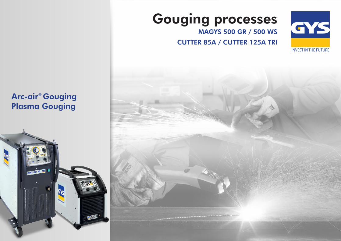
Arc-air® GougingPlasma Gouging
Gouging processesMAGYS 500 GR / 500 WS
CUTTER 85A / CUTTER 125A TRI
June 2017 - Gouging processes2
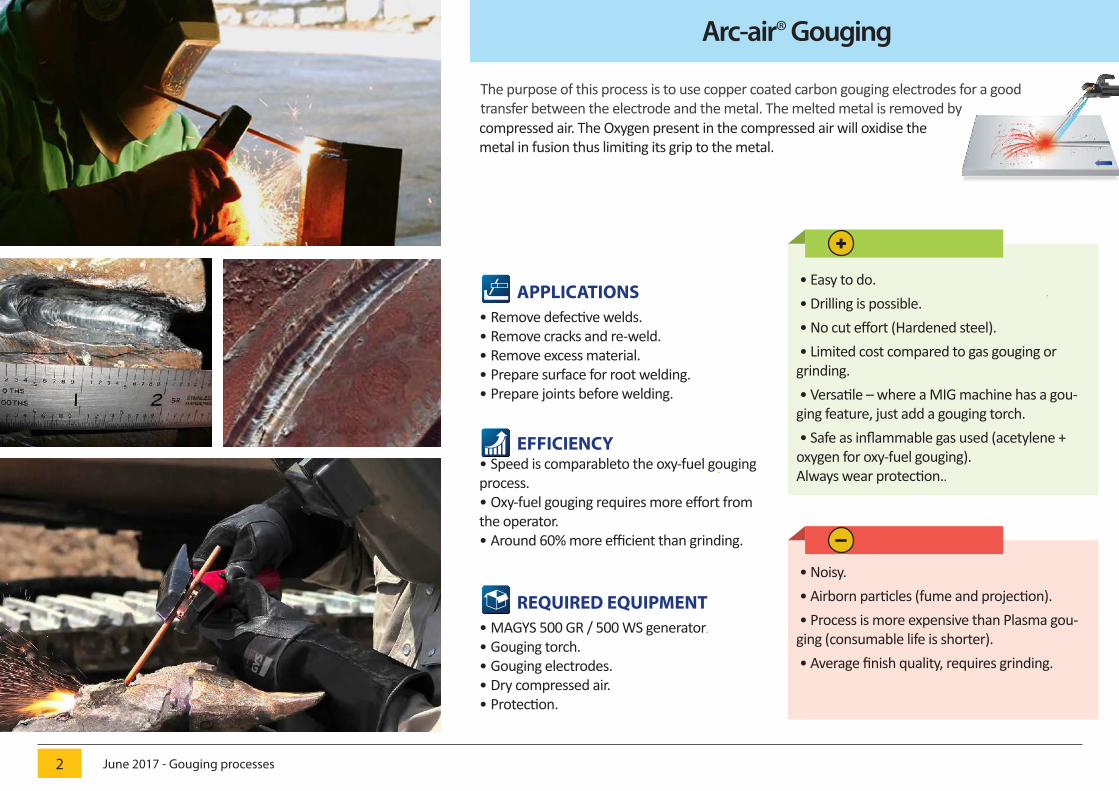
The purpose of this process is to use copper coated carbon gouging electrodes for a goodtransfer between the electrode and the metal. The melted metal is removed by
APPLICATIONS• Remove defective welds.• Remove cracks and re-weld.• Remove excess material.• Prepare surface for root welding.• Prepare joints before welding.
EFFICIENCY• Speed is comparableto the oxy-fuel gouging process.• Oxy-fuel gouging requires more effort from the operator.• Around 60% more efficient than grinding.
compressed air. The Oxygen present in the compressed air will oxidise the metal in fusion thus limiting its grip to the metal.
• Easy to do. • Drilling is possible. • No cut effort (Hardened steel). • Limited cost compared to gas gouging or grinding. • Versatile – where a MIG machine has a gou-ging feature, just add a gouging torch. • Safe as inflammable gas used (acetylene + oxygen for oxy-fuel gouging). Always wear protection..
Arc-air® Gouging
REQUIRED EQUIPMENT• MAGYS 500 GR / 500 WS generator.
• Gouging torch.• Gouging electrodes.• Dry compressed air.• Protection.
• Noisy. • Airborn particles (fume and projection). • Process is more expensive than Plasma gou-ging (consumable life is shorter). • Average finish quality, requires grinding.
June 2017 - Gouging processes3
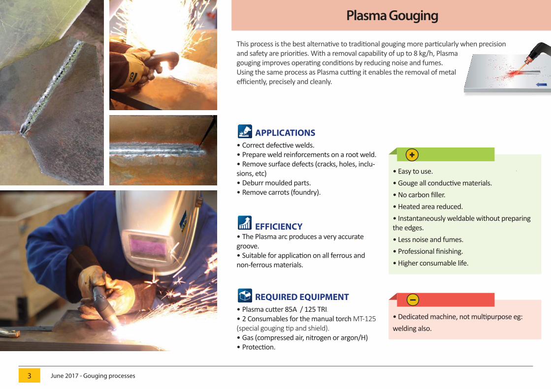
This process is the best alternative to traditional gouging more particularly when precision and safety are priorities. With a removal capability of up to 8 kg/h, Plasma gouging improves operating conditions by reducing noise and fumes. Using the same process as Plasma cutting it enables the removal of metal efficiently, precisely and cleanly.
APPLICATIONS• Correct defective welds.• Prepare weld reinforcements on a root weld.• Remove surface defects (cracks, holes, inclu-sions, etc)• Deburr moulded parts.• Remove carrots (foundry).
EFFICIENCY• The Plasma arc produces a very accurate groove.• Suitable for application on all ferrous and non-ferrous materials.
• Easy to use.• Gouge all conductive materials.• No carbon filler.• Heated area reduced.• Instantaneously weldable without preparing the edges.• Less noise and fumes.• Professional finishing.• Higher consumable life.
Plasma Gouging
REQUIRED EQUIPMENT• Plasma cutter 85A / 125 TRI.• 2 Consumables for the manual torch MT-125 (special gouging tip and shield).• Gas (compressed air, nitrogen or argon/H)• Protection.
• Dedicated machine, not multipurpose eg: welding also.
-
June 2017 - Gouging processes4
Accessories and consumables
1
Gougingelectrode
holder1000 A
2Gougingadaptor
5 m
3 Gougingelectrodes
041516
Ø 6,4 mm (x50) 086081Ø 8 mm (x50) 086098
040670
Arc Air® Gouging - MAGYS 500 GR / 500 WS
1ManualTorch
MT-125
2 Shield and tip(special gouging)
039254 (x1)
Plasma Gouging - CUTTER 85A / 125A TRI
65A<85A - 039261 (x5)105A - 029278 (x5)125A - 029285 (x5)
6m - 03950612m - 039513
Electrode Maximumcurrent
Weightof metalremoved
Groove profilDrilling Ø
Width Depth
ø 4 x 305 mm 250 A 0,6 kg/h 6-8 mm 3-4 mm 8 mm
ø 5 x 305 mm 300 A 0,7 kg/h 7-9 mm 3-5 mm 8 mm
ø 6,4 x 305 mm 400 A 1 kg/h 9-11 mm 4-6 mm 8 mm
ø 8 x 305 mm 450 A 2 kg/h 11-13 mm 6-9 mm 12 mm
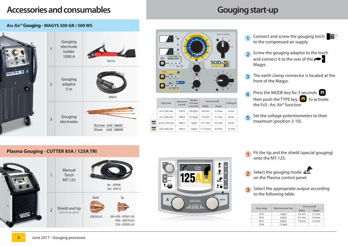
Gouging start-up
Fit the tip and the shield (special gouging)onto the MT-125.
Select the gouging mode on the Plasma control panel.
Select the appropriate output according to the following table.
1
2
3
Connect and screw the gouging torch to the compressed air supply.
Screw the gouging adaptor to the torchand connect it to the rear of the Magys.
The earth clamp connector is located at thefront of the Magys.
Press the MODE key for 3 seconds then push the TYPE key to activatethe Fc0 : Arc Air® function
Set the voltage potentiometers to theirmaximum (position 3-10).
1
2
3
4
5
Amp range Metal removal rateGroove profil
Width Depth45 A 2 kg/h 5-6 mm 2-3 mm65 A 4 kg/h 6-7 mm 3-4 mm85 A 8 kg/h 7-8 mm 5-6 mm125A 12 kg/h - -
OPTIMAL SYNERGIC
+1
+2
+3
+4-4
-3
-2
-1
MANUALm/min 241
5
10 15
20
SYNERGIC
12
3
Fe(CO2)
Fe/CrNi(Ar+CO2)
1,00,8
2T 4T DELAY
WIRE
TYPE
ø4
3 5
2 6
1 7
8
910
SYNERGIC
Alu(Ar)
1,2
MADE IN FR ANCE
SPOT
V
A
MANUAL
2 3
1 4
50,1
0,5
SPOT • DELAYs
2 3
1 4
5
AUTO
SYN TEST
MANUAL
mm
m/minpress 3s
500AHEAVY DUT Y C YCLE
S Y N E R G I C
Shield Tip